Embed Size (px)
Citation preview
Low voltage circuit breakers
Super Solution
ComprehensiveCatalogue
2006
A-5. Mounting & ConnectionTD &TS MCCB Index
Fixed mounting
Connecting terminal & conductor
Safety clearance
Example of installation
A-5-1
A-5-2
A-5-3
A-5-6
Mounting & Connection
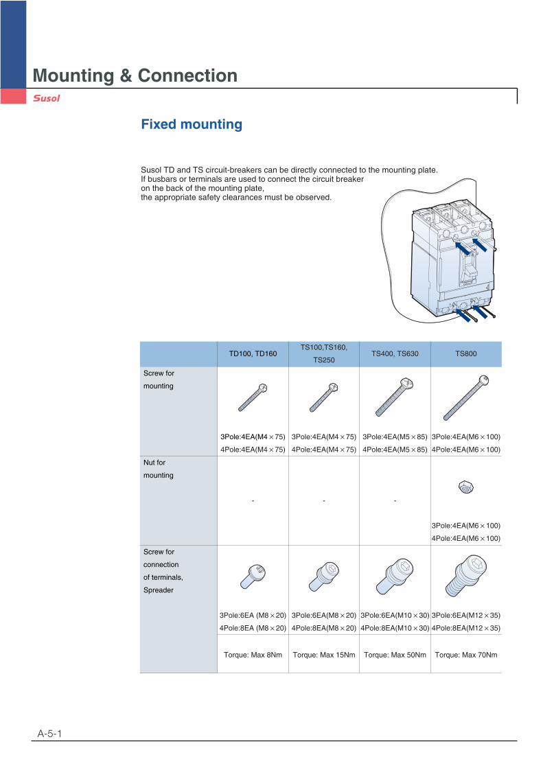
Fixed mounting
Susol TD and TS circuit-breakers can be directly connected to the mounting plate.If busbars or terminals are used to connect the circuit breaker on the back of the mounting plate,the appropriate safety clearances must be observed.
A-5-1
Screw for
mounting
Nut for
mounting
Screw for
connection
of terminals,
Spreader
TD100, TD160
3Pole:4EA(M4 75)
4Pole:4EA(M4 75)
3Pole:4EA(M4 75)
4Pole:4EA(M4 75)
3Pole:4EA(M5 85)
4Pole:4EA(M5 85)
3Pole:4EA(M6 100)
4Pole:4EA(M6 100)
3Pole:4EA(M6 100)
4Pole:4EA(M6 100)
- - -
3Pole:6EA (M8 20)
4Pole:8EA (M8 20)
3Pole:6EA(M8 20)
4Pole:8EA(M8 20)
3Pole:6EA(M10 30)
4Pole:8EA(M10 30)
3Pole:6EA(M12 35)
4Pole:8EA(M12 35)
Torque: Max 8Nm Torque: Max 15Nm Torque: Max 50Nm Torque: Max 70Nm
TS100,TS160,
TS250TS400, TS630 TS800
Mounting & Connection
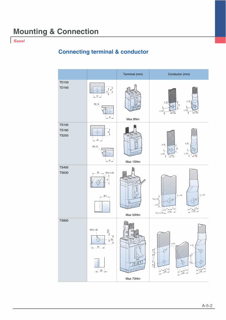
Connecting terminal & conductor
A-5-2
18
8
23
22
M8 20
20
28
22
M8 20
15
26.1
30 M10 L30
51
16.5
33
M12 35
26
TD100
TD160
TS100
TS160
TS250
TS400
TS630
TS800
Max 8Nm
88
1025
21
2510
Max 15Nm
Max 50Nm
3745
3745
19
5050
50
15
1212
==
== = =
Max 70Nm
Terminal (mm) Conductor (mm)
Mounting & Connection
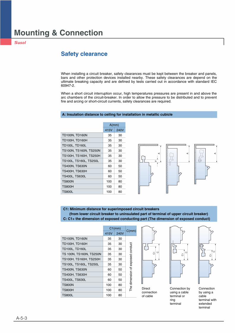
Safety clearance
When installing a circuit breaker, safety clearances must be kept between the breaker and panels,bars and other protection devices installed nearby. These safety clearances are depend on theultimate breaking capacity and are defined by tests carried out in accordance with standard IEC60947-2.
When a short circuit interruption occur, high temperatures pressures are present in and above thearc chambers of the circuit-breaker. In order to allow the pressure to be distributed and to preventfire and arcing or short-circuit currents, safety clearances are required.
A-5-3
A(mm)
415V 240V
TD100N, TD160N 35 30
TD100H, TD160H 35 30
TD100L, TD160L 35 30
TS100N, TS160N, TS250N 35 30
TS100H, TS160H, TS250H 35 30
TS100L, TS160L, TS250L 35 30
TS400N, TS630N 60 50
TS400H, TS630H 60 50
TS400L, TS630L 60 50
TS800N 100 80
TS800H 100 80
TS800L 100 80
Directconnectionof cable
Connection byusing a cableterminal or ringterminal
Connectionby using acableterminal withextendedterminal
The
dim
ensi
on o
f exp
osed
con
duct
AF
A A
C1
C1
C1
C C C
C1(mm)C(mm)
415V 240V
TD100N, TD160N 35 30
TD100H, TD160H 35 30
TD100L, TD160L 35 30
TS 100N, TS160N, TS250N 35 30
TS100H, TS160H, TS250H 35 30
TS100L, TS160L, TS250L 35 30
TS400N, TS630N 60 50
TS400H, TS630H 60 50
TS400L, TS630L 60 50
TS800N 100 80
TS800H 100 80
TS800L 100 80
A: Insulation distance to ceiling for installation in metallic cubicle
C1: Minimum distance for superimposed circuit breakers(from lower circuit breaker to uninsulated part of terminal of upper circuit breaker)
C: C1+ the dimension of exposed conducting part (The dimension of exposed conduct)
Mounting & Connection
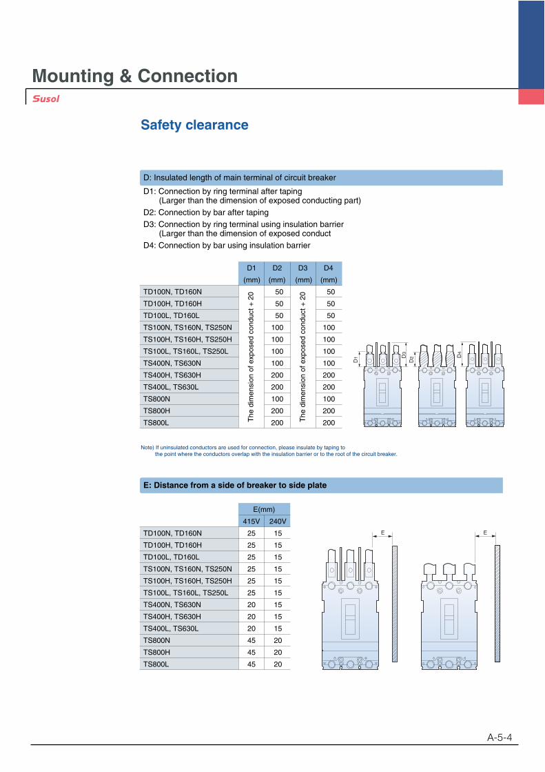
Safety clearance
A-5-4
Note) If uninsulated conductors are used for connection, please insulate by taping tothe point where the conductors overlap with the insulation barrier or to the root of the circuit breaker.
D1 D
3
D2 D
4
E(mm)
415V 240V
TD100N, TD160N 25 15
TD100H, TD160H 25 15
TD100L, TD160L 25 15
TS100N, TS160N, TS250N 25 15
TS100H, TS160H, TS250H 25 15
TS100L, TS160L, TS250L 25 15
TS400N, TS630N 20 15
TS400H, TS630H 20 15
TS400L, TS630L 20 15
TS800N 45 20
TS800H 45 20
TS800L 45 20
E E
E: Distance from a side of breaker to side plate
D: Insulated length of main terminal of circuit breaker
D1: Connection by ring terminal after taping (Larger than the dimension of exposed conducting part)
D2: Connection by bar after tapingD3: Connection by ring terminal using insulation barrier
(Larger than the dimension of exposed conductD4: Connection by bar using insulation barrier
The
dim
ensi
on o
f exp
osed
con
duct
+ 2
0
The
dim
ensi
on o
f exp
osed
con
duct
+ 2
0
D1 D2 D3 D4
(mm) (mm) (mm) (mm)
TD100N, TD160N 50 50
TD100H, TD160H 50 50
TD100L, TD160L 50 50
TS100N, TS160N, TS250N 100 100
TS100H, TS160H, TS250H 100 100
TS100L, TS160L, TS250L 100 100
TS400N, TS630N 100 100
TS400H, TS630H 200 200
TS400L, TS630L 200 200
TS800N 100 100
TS800H 200 200
TS800L 200 200
Mounting & Connection
Safety clearance
A-5-5
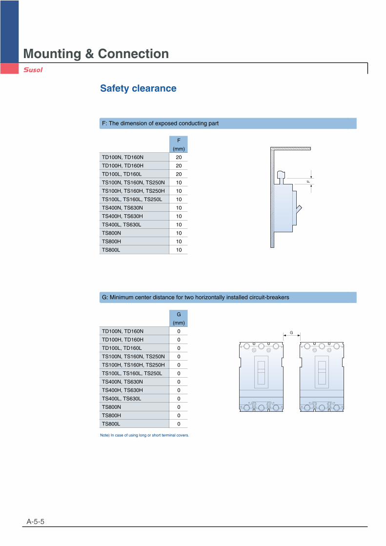
Note) In case of using long or short terminal covers.
F
(mm)
TD100N, TD160N 20
TD100H, TD160H 20
TD100L, TD160L 20
TS100N, TS160N, TS250N 10
TS100H, TS160H, TS250H 10
TS100L, TS160L, TS250L 10
TS400N, TS630N 10
TS400H, TS630H 10
TS400L, TS630L 10
TS800N 10
TS800H 10
TS800L 10
F
F: The dimension of exposed conducting part
G
(mm)
TD100N, TD160N 0
TD100H, TD160H 0
TD100L, TD160L 0
TS100N, TS160N, TS250N 0
TS100H, TS160H, TS250H 0
TS100L, TS160L, TS250L 0
TS400N, TS630N 0
TS400H, TS630H 0
TS400L, TS630L 0
TS800N 0
TS800H 0
TS800L 0
G
G: Minimum center distance for two horizontally installed circuit-breakers
Mounting & Connection
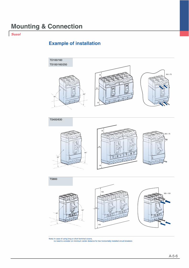
Example of installation
Note) In case of using long or short terminal covers, no need to consider on minimum center distance for two horizontally installed circuit-breakers
A-5-6
M4 75
90
25
35
35
90
M5 75
60
20
60
90
90
100
100
45
90
90
M6 100
TD100/160
TS100/160/250
TS400/630
TS800