Embed Size (px)
Citation preview
Low Voltage AC Drives for HVAC Applications
24A1-E-0068c
HVACHigh performance drives enabled by the comprehensive use of Fuji Electric Technology.
Easy maintenance for the end-user, ensures safety and protects the environment.
Opens up possiblebillities for the new generation.
Smile to the Environment
Phone: 800.894.0412 - Fax: 888.723.4773 - Web: www.clrwtr.com - Email: [email protected]

Smile to the Environment
FRENIC-HVAC~ Energy Saving for the Environment and the Future ~
Fuji Electric’s inverters save the energy consumed in fans and pumps for HVAC operations and reduce costs. The FRENIC-HVAC series controls water and air flow rates, pressure, and temperature with the fan and pump optimization.
The first slim-type inverter specialized in energy-saving from Fuji Electric.Achieves a great effect on energy-saving for fans and pumps!Contributes drastically to cost reduction by cutting power consumption!
Phone: 800.894.0412 - Fax: 888.723.4773 - Web: www.clrwtr.com - Email: [email protected]
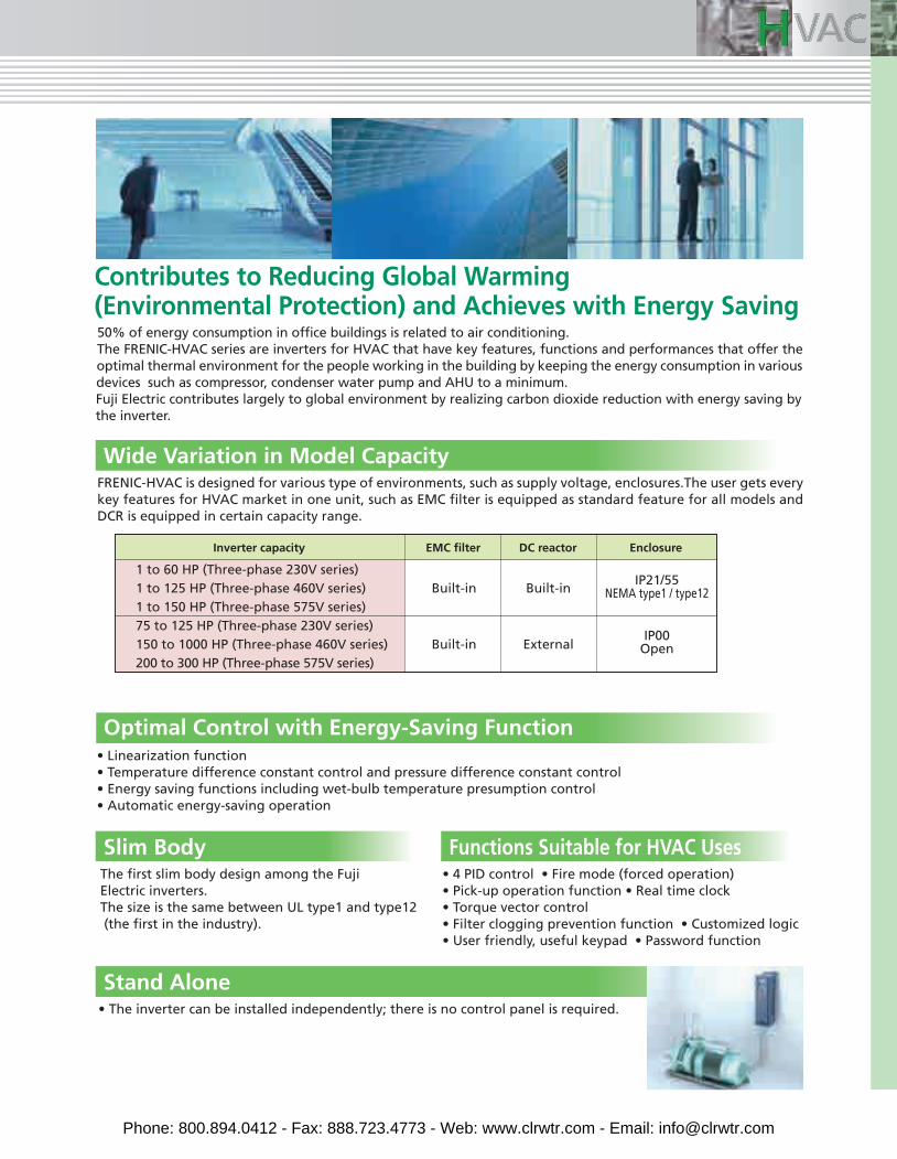
Contributes to Reducing Global Warming (Environmental Protection) and Achieves with Energy Saving
Optimal Control with Energy-Saving Function• Linearization function• Temperature difference constant control and pressure difference constant control• Energy saving functions including wet-bulb temperature presumption control• Automatic energy-saving operation
Slim BodyThe first slim body design among the FujiElectric inverters.The size is the same between UL type1 and type12(the first in the industry).
Functions Suitable for HVAC Uses• 4 PID control • Fire mode (forced operation)• Pick-up operation function • Real time clock• Torque vector control• Filter clogging prevention function • Customized logic• User friendly, useful keypad • Password function
50% of energy consumption in office buildings is related to air conditioning.The FRENIC-HVAC series are inverters for HVAC that have key features, functions and performances that offer the optimal thermal environment for the people working in the building by keeping the energy consumption in various devices such as compressor, condenser water pump and AHU to a minimum. Fuji Electric contributes largely to global environment by realizing carbon dioxide reduction with energy saving by the inverter.
Stand aloneStand Alone
• The inverter can be installed independently; there is no control panel is required.
FRENIC-HVAC is designed for various type of environments, such as supply voltage, enclosures.The user gets every key features for HVAC market in one unit, such as EMC filter is equipped as standard feature for all models and DCR is equipped in certain capacity range.
Wide Variation in Model Capacity
1 to 60 HP (Three-phase 230V series)1 to 125 HP (Three-phase 460V series)1 to 150 HP (Three-phase 575V series)75 to 125 HP (Three-phase 230V series)150 to 1000 HP (Three-phase 460V series)200 to 300 HP (Three-phase 575V series)
Built-in
Built-in
Built-in
External
IP21/55NEMA type1 / type12
IP00Open
Inverter capacity EMC filter DC reactor Enclosure
Phone: 800.894.0412 - Fax: 888.723.4773 - Web: www.clrwtr.com - Email: [email protected]
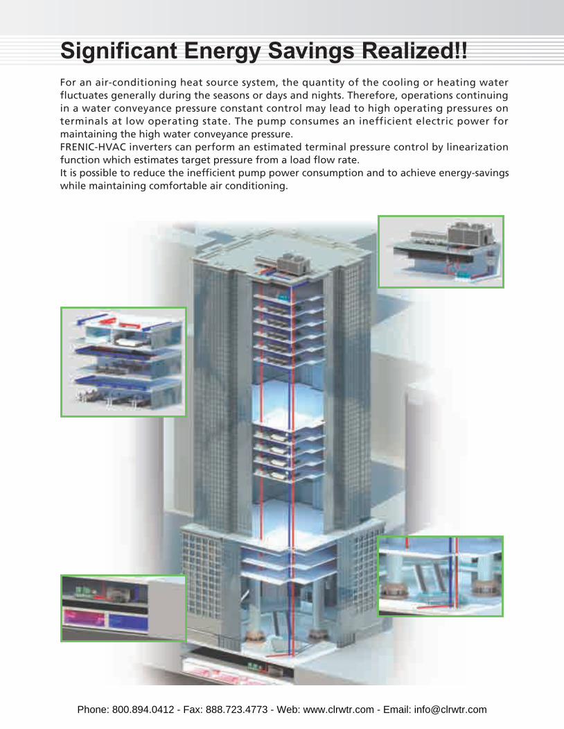
Significant Energy Savings Realized!!For an air-conditioning heat source system, the quantity of the cooling or heating water fluctuates generally during the seasons or days and nights. Therefore, operations continuing in a water conveyance pressure constant control may lead to high operating pressures on terminals at low operating state. The pump consumes an inefficient electric power for maintaining the high water conveyance pressure.FRENIC-HVAC inverters can perform an estimated terminal pressure control by linearization function which estimates target pressure from a load flow rate.It is possible to reduce the inefficient pump power consumption and to achieve energy-savings while maintaining comfortable air conditioning.
Phone: 800.894.0412 - Fax: 888.723.4773 - Web: www.clrwtr.com - Email: [email protected]
The cooling tower fan is used to cool the temperature of cooling water by emitting it into the air. The fan speed is adjusted optimally according to the cooling water temperature at the outlet. Moreover, the inverter estimates the wet-bulb temperature automatically to control the fan so that the temperature of cooling water (wet bulb) is interlocked to the air temperature. (Wet-bulb temperature presumption control)
The cooling water pump circulates the cooling water to the cooling tower in order to cool the heat generated by the Refrigeration machine. The pump speed is adjusted optimally according to the temperature and flow rate of cooling water. Moreover, the inverter can control the cooling pump so that the difference of the cooling water temperature at between the inlet and outlet is constant. (Temperature difference constant control)(*)Use the Customized logic to the part of the control
• Cooling Tower Fan
• Cooling Water Pump
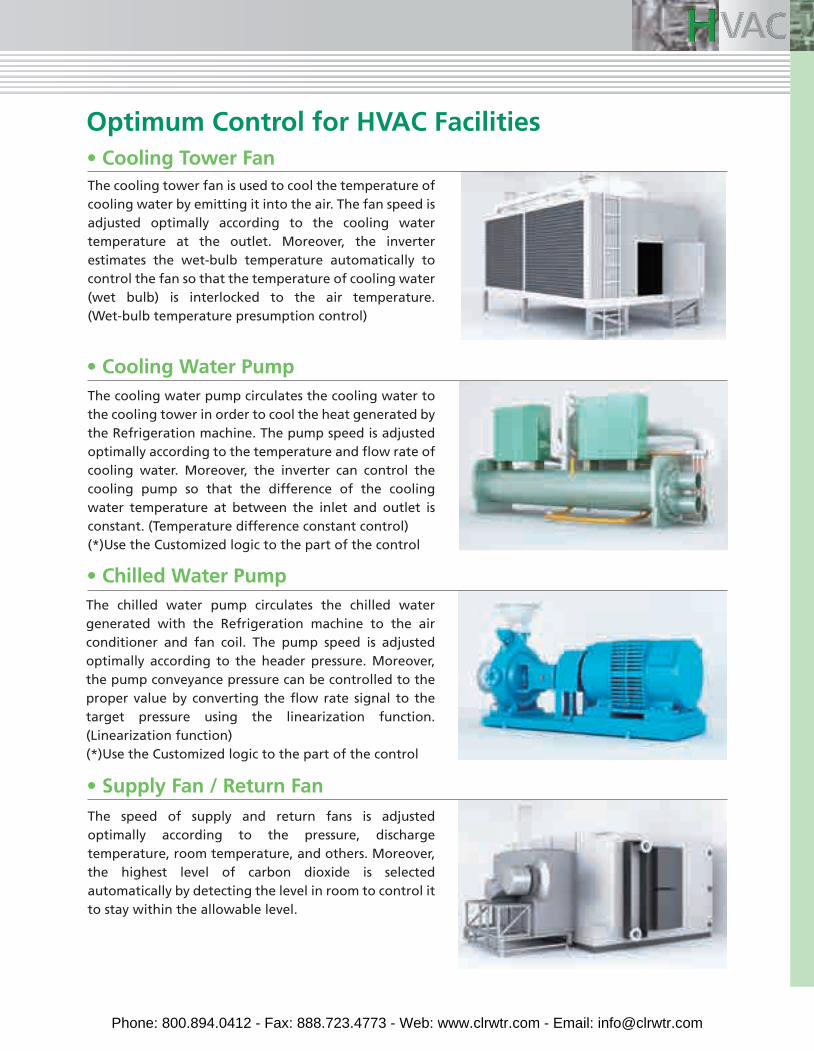
The speed of supply and return fans is adjusted optimally according to the pressure, discharge temperature, room temperature, and others. Moreover, the highest level of carbon dioxide is selected automatically by detecting the level in room to control it to stay within the allowable level.
• Supply Fan / Return Fan
• Chilled Water PumpThe chilled water pump circulates the chilled water generated with the Refrigeration machine to the air conditioner and fan coil. The pump speed is adjusted optimally according to the header pressure. Moreover, the pump conveyance pressure can be controlled to the proper value by converting the flow rate signal to the target pressure using the linearization function. (Linearization function)(*)Use the Customized logic to the part of the control
Optimum Control for HVAC Facilities
Phone: 800.894.0412 - Fax: 888.723.4773 - Web: www.clrwtr.com - Email: [email protected]
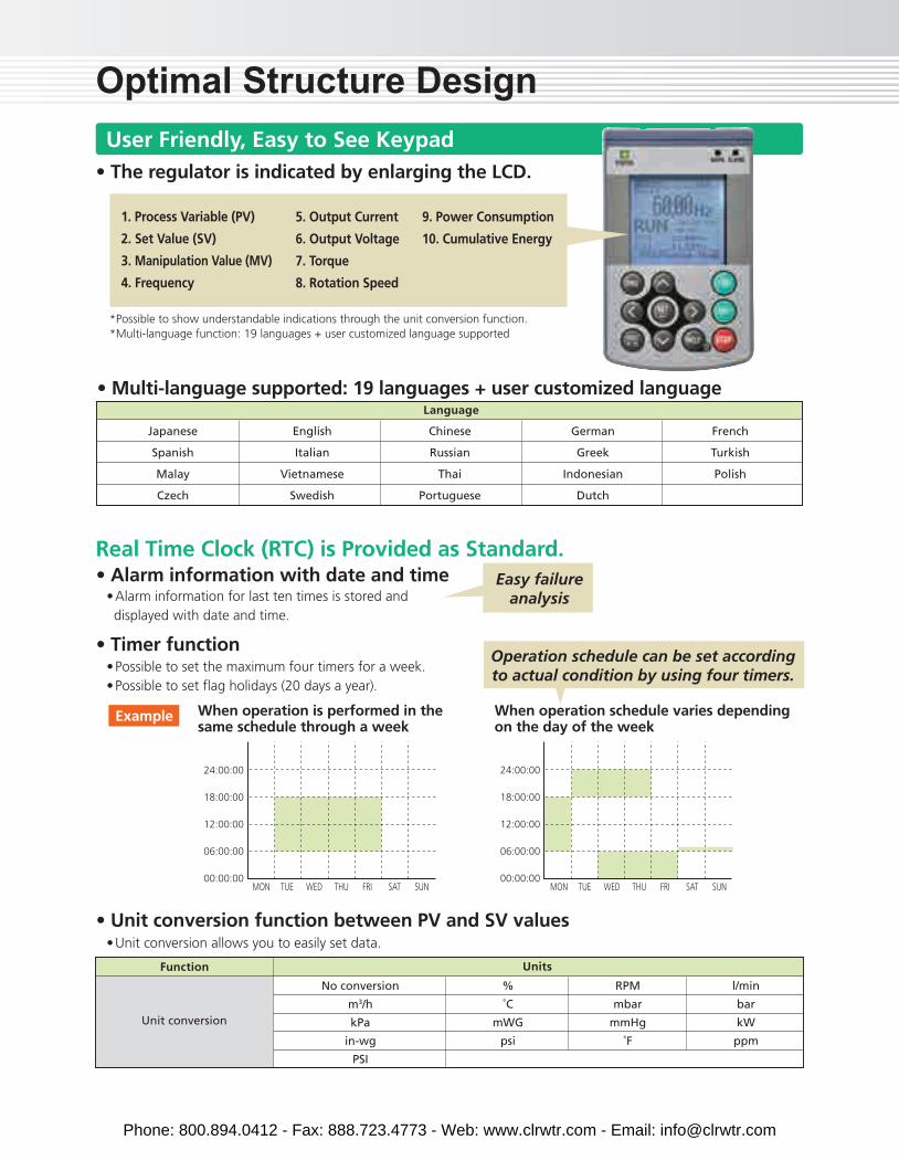
Optimal Structure DesignUser Friendly, Easy to See Keypad
1. Process Variable (PV)
2. Set Value (SV)
3. Manipulation Value (MV)
4. Frequency
• Possible to set the maximum four timers for a week.• Possible to set flag holidays (20 days a year).
• Alarm information for last ten times is stored anddisplayed with date and time.
• Unit conversion allows you to easily set data.
• Alarm information with date and time
• Unit conversion function between PV and SV values
• Timer function
Real Time Clock (RTC) is Provided as Standard.
Language
When operation is performed in the same schedule through a week
When operation schedule varies depending on the day of the week
24:00:00
18:00:00
12:00:00
06:00:00
00:00:00
Example
Easy failureanalysis
Operation schedule can be set accordingto actual condition by using four timers.
• The regulator is indicated by enlarging the LCD.
*Possible to show understandable indications through the unit conversion function.*Multi-language function: 19 languages + user customized language supported
5. Output Current
6. Output Voltage
7. Torque
8. Rotation Speed
9. Power Consumption
10. Cumulative Energy
• Multi-language supported: 19 languages + user customized language
Japanese
Spanish
Malay
Czech
English
Italian
Vietnamese
Swedish
Chinese
Russian
Thai
Portuguese
German
Greek
Indonesian
Dutch
French
Turkish
Polish
No conversion
m3/h
kPa
in-wg
PSI
%
˚C
mWG
psi
RPM
mbar
mmHg
˚F
l/min
bar
kW
ppm
Unit conversion
Function Units
24:00:00
18:00:00
12:00:00
06:00:00
00:00:00MON TUE WED THU FRI SAT SUN MON TUE WED THU FRI SAT SUN
Phone: 800.894.0412 - Fax: 888.723.4773 - Web: www.clrwtr.com - Email: [email protected]
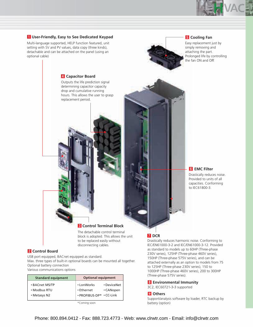
Multi-language supported, HELP function featured, unit setting with SV and PV values, data copy (three kinds), detachable and can be attached on the panel (using an optional cable)
Outputs the life prediction signal determining capacitor capacity drop and cumulative running hours. This allows the user to grasp replacement period.
USB port equipped, BACnet equipped as standard. Max. three types of built-in optional boards can be mounted all together.Optional battery connectionVarious communications options
Control Board
The detachable control terminal block is adopted. This allows the unit to be replaced easily without disconnecting cables.
Control Terminal Block
Drastically reduces harmonic noise. Conforming to IEC/EN61000-3-2 and IEC/EN61000-3-12. Provided as standard to models up to 60HP (Three-phase 230V series), 125HP (Three-phase 460V series), 150HP (Three-phase 575V series), and can be attached externally as an option to models from 75 to 125HP (Three-phase 230V series), 150 to 1000HP (Three-phase 460V series), 200 to 300HP (Three-phase 575V series).
Capacitor Board
Drastically reduces noise. Provided to units of all capacities. Conforming to IEC61800-3.
EMC Filter
Easy replacement just by simply removing and attaching the part.Prolonged life by controlling the fan ON and OFF.
Cooling Fan
DCR
3C2, IEC60721-3-3 supportedEnvironmental Immunity
Support/analysis software by loader, RTC backup by battery (option)
Others
Standard equipment Optional equipment
• BACnet MS/TP
• Modbus RTU
• Metasys N2
• LonWorks
• Ethernet
• PROFIBUS-DP*
• DeviceNet
• CANopen
• CC-Link
User-Friendly, Easy to See Dedicated Keypad
*Coming soon
Phone: 800.894.0412 - Fax: 888.723.4773 - Web: www.clrwtr.com - Email: [email protected]
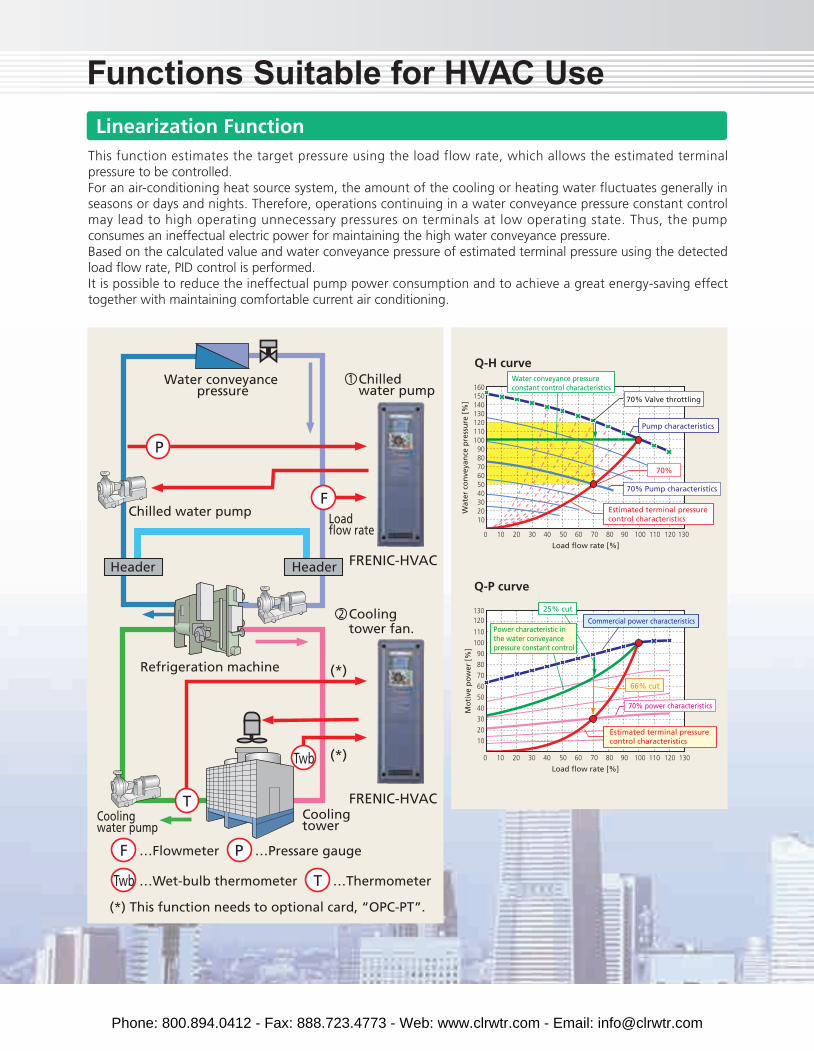
This function estimates the target pressure using the load flow rate, which allows the estimated terminal pressure to be controlled. For an air-conditioning heat source system, the amount of the cooling or heating water fluctuates generally in seasons or days and nights. Therefore, operations continuing in a water conveyance pressure constant control may lead to high operating unnecessary pressures on terminals at low operating state. Thus, the pump consumes an ineffectual electric power for maintaining the high water conveyance pressure.Based on the calculated value and water conveyance pressure of estimated terminal pressure using the detected load flow rate, PID control is performed.It is possible to reduce the ineffectual pump power consumption and to achieve a great energy-saving effect together with maintaining comfortable current air conditioning.
Functions Suitable for HVAC UseLinearization Function
100908020 30 40 50 60 7010
102030405060708090
100110120130140150160
0 110 120 130
Q-H curve
Wat
er c
on
veya
nce
pre
ssu
re [
%]
Load flow rate [%]
70%
100908020 30 40 50 60 7010
10
20
30
40
50
60
70
80
90
100
110
120130
0 110 120 130
Q-P curve
Load flow rate [%]
Mo
tive
po
wer
[%
]
66% cut
Estimated terminal pressure control characteristics
Estimated terminal pressure control characteristics
Commercial power characteristics
70% power characteristics
Pump characteristics
70% Valve throttling
Water conveyance pressure constant control characteristics
70% Pump characteristics
25% cut
Power characteristic in the water conveyance pressure constant control
FRENIC-HVAC
FRENIC-HVAC
Chilled water pump
Cooling tower fan.
Water conveyance pressure
Refrigeration machine
Coolingtower
(*)
(*)
Cooling water pump
Chilled water pump Load flow rate
HeaderHeader
P
F
…FlowmeterF
…ThermometerT
…Pressare gaugeP
…Wet-bulb thermometer
(*) This function needs to optional card, “OPC-PT”.
Twb
Twb
T
1
2
Phone: 800.894.0412 - Fax: 888.723.4773 - Web: www.clrwtr.com - Email: [email protected]
+
-
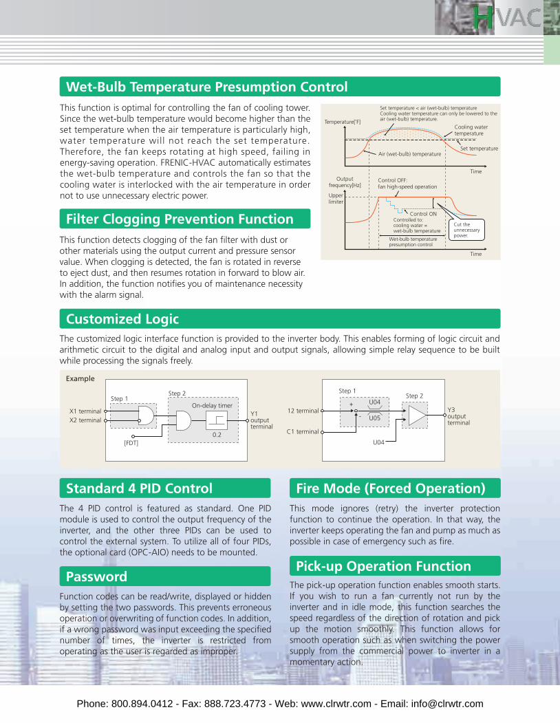
This function is optimal for controlling the fan of cooling tower. Since the wet-bulb temperature would become higher than the set temperature when the air temperature is particularly high, water temperature wil l not reach the set temperature. Therefore, the fan keeps rotating at high speed, failing in energy-saving operation. FRENIC-HVAC automatically estimates the wet-bulb temperature and controls the fan so that the cooling water is interlocked with the air temperature in order not to use unnecessary electric power.
This mode ignores (retry) the inverter protection function to continue the operation. In that way, the inverter keeps operating the fan and pump as much as possible in case of emergency such as fire.
This function detects clogging of the fan filter with dust or other materials using the output current and pressure sensor value. When clogging is detected, the fan is rotated in reverse to eject dust, and then resumes rotation in forward to blow air. In addition, the function notifies you of maintenance necessity with the alarm signal.
The customized logic interface function is provided to the inverter body. This enables forming of logic circuit and arithmetic circuit to the digital and analog input and output signals, allowing simple relay sequence to be built while processing the signals freely.
The 4 PID control is featured as standard. One PID module is used to control the output frequency of the inverter, and the other three PIDs can be used to control the external system. To utilize all of four PIDs, the optional card (OPC-AIO) needs to be mounted.
Function codes can be read/write, displayed or hidden by setting the two passwords. This prevents erroneous operation or overwriting of function codes. In addition, if a wrong password was input exceeding the specified number of times, the inverter is restricted from operating as the user is regarded as improper.
The pick-up operation function enables smooth starts.If you wish to run a fan currently not run by the inverter and in idle mode, this function searches the speed regardless of the direction of rotation and pick up the motion smoothly. This function allows for smooth operation such as when switching the power supply from the commercial power to inverter in a momentary action.
Wet-Bulb Temperature Presumption Control
Filter Clogging Prevention Function
Customized Logic
Standard 4 PID Control Fire Mode (Forced Operation)
PasswordPick-up Operation Function
Outputfrequency[Hz]
Temperature[˚F]
Wet-bulb temperature presumption control
Time
Time
Set temperature
Set temperature < air (wet-bulb) temperatureCooling water temperature can only be lowered to the air (wet-bulb) temperature.
Cooling watertemperature
Cut the unnecessary power.
Upperlimiter
Air (wet-bulb) temperature
Controlled to: cooling water = wet-bulb temperature
Control ON
Control OFF: fan high-speed operation
X1 terminal 12 terminal
C1 terminal
U04
U04
U05
Step 1Step 2
On-delay timer
Step 1Step 2
X2 terminalY1 outputterminal
Y3 outputterminal
Example
0.2[FDT]
Phone: 800.894.0412 - Fax: 888.723.4773 - Web: www.clrwtr.com - Email: [email protected]
Standard Specifications
EMC standards compliance : Category C2 (emission) / 2nd Env. (Immunity)Built-in (IEC/EN 61000-3-2 *9, IEC/EN 61000-3-12)
IP21/ IP55NEMA/UL TYPE 1, NEMA/ UL TYPE 12
C3/ 2nd.
IP00UL open type
-
10 to 1520
97% 98%
Three-phase, 200 to 220 V, 50 Hz, Three-phase, 200 to 230 V, 60 Hz
Single-phase, 200 to 220 V, 50 Hz, Single-phase, 200 to 230 V, 60 Hz
Single-phase 200 to 220 V, 50 Hz, Single-phase 200 to 230 V, 60 Hz
Standard accessory(IEC/EN 61000-3-12)
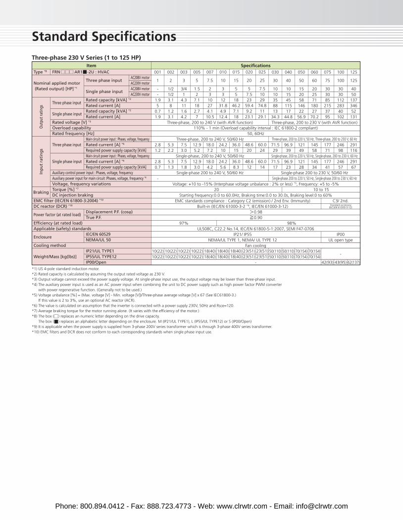
Three-phase 230 V Series (1 to 125 HP)
Type *8 FRN AR1 -2U : HVAC
Three phase input
Single phase input
Rated voltage [V] *3
Overload capabilityRated frequency [Hz]
Three phase input
Single phase input
Auxiliary control power input : Phases, voltage, frequencyAuxiliary power input for main circuit :Phases, voltage, frequency *4
Voltage, frequency variationsTorque [%] *7
DC injection brakingBraking
Out
put r
atin
gsIn
pu
t ra
tin
gs
SpecificationsItem
Three phase input
Single phase input
Rated capacity [kVA] *2
Rated current [A]Rated capacity [kVA] *2
Rated current [A]
Main circuit power input : Phases, voltage, frequencyRated current [A] *6
Required power supply capacity [kVA]Main circuit power input : Phases, voltage, frequencyRated current [A] *6
Required power supply capacity [kVA]
Displacement P.F. (cosφ)True P.F.
IEC/EN 60529NEMA/UL 50
IP21/UL TYPE1IP55/UL TYPE12IP00/Open
AC208V motorAC230V motorAC208V motorAC230V motor
001
1
--
1.95
0.71.9
2.81.2
2.80.7
-
10(22)10(22)
002
2
1/21/23.18
1.23.1
5.32.2
5.31.3
10(22)10(22)
003
3
3/41
4.3111.64.2
7.53.0
7.51.8
10(22)10(22)
005
5
1.52
7.1182.77
12.95.2
12.93.0
10(22)10(22)
007
7.5
23
10274.110.5
18.07.2
18.04.2
18(40)18(40)
Three-phase, 200 to 240 V, 50/60 Hz
Single-phase, 200 to 240 V, 50/60 Hz
Single-phase 200 to 240 V, 50/60 Hz-
Single-phase 200 to 230 V, 50/60 Hz
010
10
33
1231.84.9
12.4
24.210
24.25.6
18(40)18(40)
015
15
5518
46.27.118
36.015
36.08.3
18(40)18(40)
020
20
57.523
59.49.2
23.1
48.620
48.612
23(51)23(51)
025
25
7.51029
74.811
29.1
60.024
60.014
23(51)23(51)
110% - 1 min (Overload capability interval : IEC 61800-2 compliant)50, 60Hz
Voltage: +10 to -15% (Interphase voltage unbalance : 2% or less) *5, Frequency: +5 to -5%
Starting frequency:0.0 to 60.0Hz, Braking time:0.0 to 30.0s, Braking level:0 to 60%
0.98 0.90
UL508C, C22.2 No.14, IEC/EN 61800-5-1:2007, SEMI F47-0706
Fan cooling
-
Three-phase, 200 to 230 V (with AVR function)Three-phase, 200 to 240 V (with AVR function)
030
30
1010358813
34.3
71.529
71.517
50(110)50(110)
040
40
101545
11517
44.8
96.939
96.923
50(110)50(110)
050
50
152058
14622
56.9
12149
12128
70(154)70(154)
060
60
202571
18027
70.2
14558
14534
70(154)70(154)
075
75
3030852153795
17771
17741
42(93)
100
100
3030
11228340
102
24698
24657
43(95)
125
125
4050
13734652
131
291116
29167
62(137)
*1) US 4-pole standard induction motor.*2) Rated capacity is calculated by assuming the output rated voltage as 230 V.*3) Output voltage cannot exceed the power supply voltage. At single-phase input use, the output voltage may be lower than three-phase input.*4) The auxiliary power input is used as an AC power input when combining the unit to DC power supply such as high power factor PWM converter with power regenerative function. (Generally not to be used.)*5) Voltage unbalance [%] = (Max. voltage [V] - Min. voltage [V])/Three-phase average voltage [V] x 67 (See IEC61800-3.) If this value is 2 to 3%, use an optional AC reactor (ACR).*6) The value is calculated on assumption that the inverter is connected with a power supply 230V, 50Hz and Rsce=120.*7) Average braking torque for the motor running alone. (It varies with the efficiency of the motor.)*8) The box ( ) replaces an numeric letter depending on the drive capacity. The box ( ) replaces an alphabetic letter depending on the enclosure. M (IP21/UL TYPE1), L (IP55/UL TYPE12) or S (IP00/Open)*9) It is applicable when the power supply is supplied from 3-phase 200V series transformer which is through 3-phase 400V series transformer.*10) EMC filters and DCR does not conform to each corresponding standards when single phase input use.
Nominal applied motor (Rated output) [HP] *1
EMC filter (IEC/EN 61800-3:2004) *10
DC reactor (DCR) *10
Power factor (at rated load)
Efficiency (at rated load)Applicable (safety) standards
Enclosure
Cooling method
Weight/Mass [kg(lbs)]
Phone: 800.894.0412 - Fax: 888.723.4773 - Web: www.clrwtr.com - Email: [email protected]
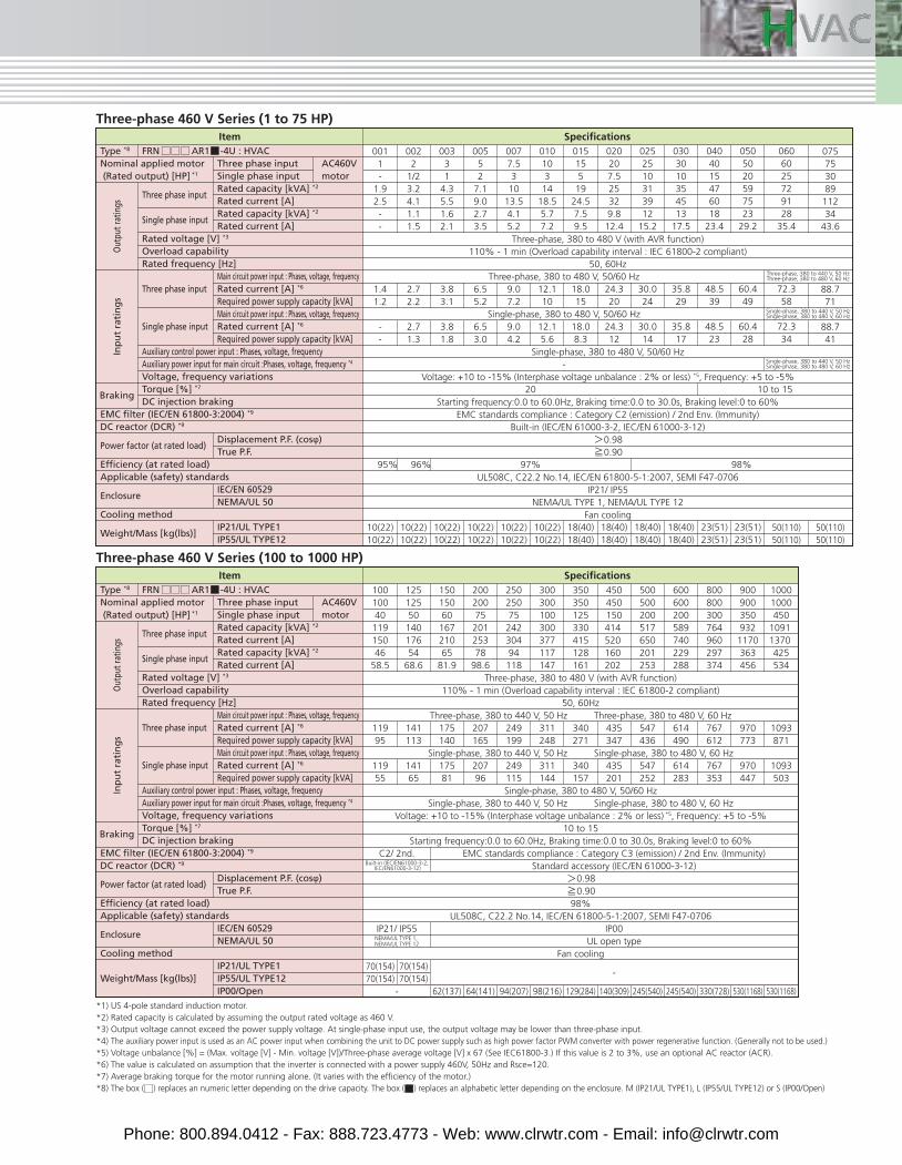
Three-phase 460 V Series (1 to 75 HP)
Type *8 FRN AR1 -4U : HVAC
Three phase input
Single phase input
Rated voltage [V] *3
Overload capabilityRated frequency [Hz]
Three phase input
Single phase input
Auxiliary control power input : Phases, voltage, frequencyAuxiliary power input for main circuit :Phases, voltage, frequency *4
Voltage, frequency variationsTorque [%] *7
DC injection brakingBraking
Out
put r
atin
gsIn
pu
t ra
tin
gs
*1) US 4-pole standard induction motor.*2) Rated capacity is calculated by assuming the output rated voltage as 460 V.*3) Output voltage cannot exceed the power supply voltage. At single-phase input use, the output voltage may be lower than three-phase input.*4) The auxiliary power input is used as an AC power input when combining the unit to DC power supply such as high power factor PWM converter with power regenerative function. (Generally not to be used.)*5) Voltage unbalance [%] = (Max. voltage [V] - Min. voltage [V])/Three-phase average voltage [V] x 67 (See IEC61800-3.) If this value is 2 to 3%, use an optional AC reactor (ACR).*6) The value is calculated on assumption that the inverter is connected with a power supply 460V, 50Hz and Rsce=120.*7) Average braking torque for the motor running alone. (It varies with the efficiency of the motor.)*8) The box ( ) replaces an numeric letter depending on the drive capacity. The box ( ) replaces an alphabetic letter depending on the enclosure. M (IP21/UL TYPE1), L (IP55/UL TYPE12) or S (IP00/Open)
SpecificationsItem
Nominal applied motor (Rated output) [HP] *1
EMC filter (IEC/EN 61800-3:2004) *9
DC reactor (DCR) *9
Power factor (at rated load)
Efficiency (at rated load)Applicable (safety) standards
Enclosure
Cooling method
Weight/Mass [kg(lbs)]
Three phase inputSingle phase inputRated capacity [kVA] *2
Rated current [A]Rated capacity [kVA] *2
Rated current [A]
Main circuit power input : Phases, voltage, frequencyRated current [A] *6
Required power supply capacity [kVA]Main circuit power input : Phases, voltage, frequencyRated current [A] *6
Required power supply capacity [kVA]
Displacement P.F. (cosφ)True P.F.
IEC/EN 60529NEMA/UL 50
IP21/UL TYPE1IP55/UL TYPE12
AC460V motor
0011-
1.92.5--
1.41.2
--
10(22)10(22)
0022
1/23.24.11.11.5
2.72.2
2.71.3
10(22)10(22)
00331
4.35.51.62.1
3.83.1
3.81.8
10(22)10(22)
00552
7.19.02.73.5
6.55.2
6.53.0
10(22)10(22)
0077.53
1013.54.15.2
9.07.2
9.04.2
10(22)10(22)
010103
1418.55.77.2
12.110
12.15.6
10(22)10(22)
015155
1924.57.59.5
18.015
18.08.3
18(40)18(40)
Three-phase, 380 to 480 V, 50/60 Hz
Single-phase, 380 to 480 V, 50/60 Hz
-
20 10 to 15
97%95% 96% 98%
020207.525329.812.4
24.320
24.312
18(40)18(40)
0252510313912
15.2
30.024
30.014
18(40)18(40)
0303010354513
17.5
35.829
35.817
18(40)18(40)
0404015476018
23.4
48.539
48.523
23(51)23(51)
0505020597523
29.2
60.449
60.428
23(51)23(51)
0606025729128
35.4
72.358
72.334
50(110)50(110)
075753089
11234
43.6
88.771
88.741
50(110)50(110)
Three-phase, 380 to 440 V, 50 HzThree-phase, 380 to 480 V, 60 Hz
Single-phase, 380 to 440 V, 50 HzSingle-phase, 380 to 480 V, 60 Hz
Single-phase, 380 to 440 V, 50 HzSingle-phase, 380 to 480 V, 60 Hz
Three-phase 460 V Series (100 to 1000 HP)
Type *8 FRN AR1 -4U : HVAC
Three phase input
Single phase input
Rated voltage [V] *3
Overload capabilityRated frequency [Hz]
Three phase input
Single phase input
Auxiliary control power input : Phases, voltage, frequencyAuxiliary power input for main circuit :Phases, voltage, frequency *4
Voltage, frequency variationsTorque [%] *7
DC injection brakingBraking
Out
put r
atin
gsIn
pu
t ra
tin
gs
SpecificationsItem
Three phase inputSingle phase inputRated capacity [kVA] *2
Rated current [A]Rated capacity [kVA] *2
Rated current [A]
Main circuit power input : Phases, voltage, frequencyRated current [A] *6
Required power supply capacity [kVA]Main circuit power input : Phases, voltage, frequencyRated current [A] *6
Required power supply capacity [kVA]
Displacement P.F. (cosφ)True P.F.
IEC/EN 60529NEMA/UL 50
IP21/UL TYPE1IP55/UL TYPE12IP00/Open
AC460V motor
10010040
11915046
58.5
11995
11955
70(154)70(154)
1251255014017654
68.6
141113
14165
70(154)70(154)
15015060
16721065
81.9
175140
17581
62(137)
20020075
20125378
98.6
207165
20796
64(141)
2502507524230494118
249199
249115
94(207)
300300100300377117147
311248
311144
98(216)
350350125330415128161
340271
340157
129(284)
Three-phase, 380 to 480 V (with AVR function)110% - 1 min (Overload capability interval : IEC 61800-2 compliant)
50, 60HzThree-phase, 380 to 440 V, 50 Hz Three-phase, 380 to 480 V, 60 Hz
Single-phase, 380 to 440 V, 50 Hz Single-phase, 380 to 480 V, 60 Hz
Single-phase, 380 to 480 V, 50/60 HzSingle-phase, 380 to 440 V, 50 Hz Single-phase, 380 to 480 V, 60 Hz
Voltage: +10 to -15% (Interphase voltage unbalance : 2% or less) *5, Frequency: +5 to -5%10 to 15
Starting frequency:0.0 to 60.0Hz, Braking time:0.0 to 30.0s, Braking level:0 to 60%
0.98 0.9098%
UL508C, C22.2 No.14, IEC/EN 61800-5-1:2007, SEMI F47-0706
Fan cooling
C2/ 2nd.
IP21/ IP55
-
EMC standards compliance : Category C3 (emission) / 2nd Env. (Immunity)Standard accessory (IEC/EN 61000-3-12)
IP00UL open type
-
450450150414 520 160 202
435347
435201
140(309)
500500200517650201253
547436
547252
245(540)
600600200589740229288
614490
614283
245(540)
800800300764960297374
767612
767353
330(728)
900900350932
1170363456
970773
970447
530(1168)
10001000450
1091 1370 425534
1093871
1093503
530(1168)
Built-in (IEC/EN61000-3-2, IEC/EN61000-3-12)
NEMA/UL TYPE 1, NEMA/UL TYPE 12
Three-phase, 380 to 480 V (with AVR function)110% - 1 min (Overload capability interval : IEC 61800-2 compliant)
50, 60Hz
Single-phase, 380 to 480 V, 50/60 Hz
Voltage: +10 to -15% (Interphase voltage unbalance : 2% or less) *5, Frequency: +5 to -5%
Starting frequency:0.0 to 60.0Hz, Braking time:0.0 to 30.0s, Braking level:0 to 60%EMC standards compliance : Category C2 (emission) / 2nd Env. (Immunity)
Built-in (IEC/EN 61000-3-2, IEC/EN 61000-3-12) 0.98 0.90
UL508C, C22.2 No.14, IEC/EN 61800-5-1:2007, SEMI F47-0706IP21/ IP55
NEMA/UL TYPE 1, NEMA/UL TYPE 12Fan cooling
Nominal applied motor (Rated output) [HP] *1
EMC filter (IEC/EN 61800-3:2004) *9
DC reactor (DCR) *9
Power factor (at rated load)
Efficiency (at rated load)Applicable (safety) standards
Enclosure
Cooling method
Weight/Mass [kg(lbs)]
Phone: 800.894.0412 - Fax: 888.723.4773 - Web: www.clrwtr.com - Email: [email protected]
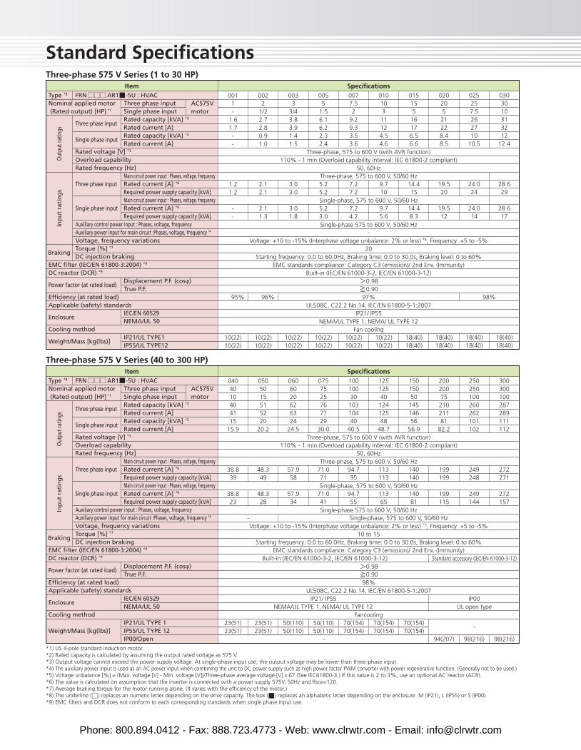
Standard SpecificationsThree-phase 575 V Series (1 to 30 HP)
Type *8 FRN AR1 -5U : HVAC
Three phase input
Single phase input
Rated voltage [V] *3
Overload capabilityRated frequency [Hz]
Three phase input
Single phase input
Auxiliary control power input : Phases, voltage, frequencyAuxiliary power input for main circuit :Phases, voltage, frequency *4
Voltage, frequency variationsTorque [%] *7
DC injection brakingBraking
Out
put r
atin
gsIn
pu
t ra
tin
gs
*1) US 4-pole standard induction motor.*2) Rated capacity is calculated by assuming the output rated voltage as 575 V.*3) Output voltage cannot exceed the power supply voltage. At single-phase input use, the output voltage may be lower than three-phase input.*4) The auxiliary power input is used as an AC power input when combining the unit to DC power supply such as high power factor PWM converter with power regenerative function. (Generally not to be used.)*5) Voltage unbalance [%] = (Max. voltage [V] - Min. voltage [V])/Three-phase average voltage [V] x 67 (See IEC61800-3.) If this value is 2 to 3%, use an optional AC reactor (ACR).*6) The value is calculated on assumption that the inverter is connected with a power supply 575V, 50Hz and Rsce=120.*7) Average braking torque for the motor running alone. (It varies with the efficiency of the motor.)*8) The underline ( ) replaces an numeric letter depending on the drive capacity. The box ( ) replaces an alphabetic letter depending on the enclosure. M (IP21), L (IP55) or S (IP00)*9) EMC filters and DCR does not conform to each corresponding standards when single phase input use.
SpecificationsItem
Nominal applied motor (Rated output) [HP] *1
EMC filter (IEC/EN 61800-3:2004) *9
DC reactor (DCR) *9
Power factor (at rated load)
Efficiency (at rated load)Applicable (safety) standards
Enclosure
Cooling method
Weight/Mass [kg(lbs)]
Three phase inputSingle phase inputRated capacity [kVA] *2
Rated current [A]Rated capacity [kVA] *2
Rated current [A]
Main circuit power input : Phases, voltage, frequencyRated current [A] *6
Required power supply capacity [kVA]Main circuit power input : Phases, voltage, frequencyRated current [A] *6
Required power supply capacity [kVA]
Displacement P.F. (cosφ)True P.F.
IEC/EN 60529NEMA/UL 50
IP21/UL TYPE1IP55/UL TYPE12
AC575V motor
0011-
1.61.7--
1.21.2
--
10(22)10(22)
0022
1/22.72.80.91.0
2.12.1
2.11.3
10(22)10(22)
0033
3/43.83.91.41.5
3.03.0
3.01.8
10(22)10(22)
0055
1.56.16.22.32.4
5.25.2
5.23.0
10(22)10(22)
0077.52
9.29.33.53.6
7.27.2
7.24.2
10(22)10(22)
01010311124.54.6
9.710
9.75.6
10(22)10(22)
015155
16176.56.6
14.415
14.48.3
18(40)18(40)
97%95% 96% 98%
02020521228.48.5
19.520
19.512
18(40)18(40)
025257.5262710
10.5
24.024
24.014
18(40)18(40)
0303010313212
12.4
28.629
28.617
18(40)18(40)
Three-phase 575 V Series (40 to 300 HP)
Type *8 FRN AR1 -5U : HVAC
Three phase input
Single phase input
Rated voltage [V] *3
Overload capabilityRated frequency [Hz]
Three phase input
Single phase input
Auxiliary control power input : Phases, voltage, frequencyAuxiliary power input for main circuit :Phases, voltage, frequency *4
Voltage, frequency variationsTorque [%] *7
DC injection brakingBraking
Out
put r
atin
gsIn
pu
t ra
tin
gs
SpecificationsItem
Three phase inputSingle phase inputRated capacity [kVA] *2
Rated current [A]Rated capacity [kVA] *2
Rated current [A]
Main circuit power input : Phases, voltage, frequencyRated current [A] *6
Required power supply capacity [kVA]Main circuit power input : Phases, voltage, frequencyRated current [A] *6
Required power supply capacity [kVA]
Displacement P.F. (cosφ)True P.F.
IEC/EN 60529NEMA/UL 50
IP21/UL TYPE 1IP55/UL TYPE 12IP00/Open
AC575V motor
0404010404115
15.9
38.839
38.823
23(51)23(51)
0505015515220
20.2
48.349
48.328
23(51)23(51)
0606020626324
24.5
57.958
57.934
50(110)50(110)
0757525767729
30.0
71.071
71.041
50(110)50(110)
1001003010310440
40.5
94.795
94.755
70(154)70(154)
12512540
12412548
48.7
113113
11365
70(154)70(154)
15015050
14514656
56.9
140140
14081
70(154)70(154)
-
IP21/ IP55NEMA/UL TYPE 1, NEMA/ UL TYPE 12
Built-in (IEC/EN 61000-3-2, IEC/EN 61000-3-12)
Single-phase, 575 to 600 V, 50/60 Hz
IP00UL open type
Standard accessory (IEC/EN 61000-3-12)
-
-
20020075
21021181
82.2
199199
199115
94(207)
250250100260262101102
249248
249144
98(216)
300300100287289111112
272271
272157
98(216)
Three-phase, 575 to 600 V (with AVR function)110% - 1 min (Overload capability interval: IEC 61800-2 compliant)
50, 60HzThree-phase, 575 to 600 V, 50/60 Hz
Single-phase, 575 to 600 V, 50/60 Hz
Single-phase 575 to 600 V,50/60 Hz-
Voltage: +10 to -15% (Interphase voltage unbalance: 2% or less) *5, Frequency: +5 to -5%20
Starting frequency: 0.0 to 60.0Hz, Braking time: 0.0 to 30.0s, Braking level: 0 to 60%EMC standards compliance: Category C3 (emission)/ 2nd Env. (Immunity)
Built-in (IEC/EN 61000-3-2, IEC/EN 61000-3-12) 0.98 0.90
UL508C, C22.2 No.14, IEC/EN 61800-5-1:2007IP21/ IP55
NEMA/UL TYPE 1, NEMA/ UL TYPE 12Fan cooling
Three-phase, 575 to 600 V (with AVR function)110% - 1 min (Overload capability interval: IEC 61800-2 compliant)
50, 60HzThree-phase, 575 to 600 V, 50/60 Hz
Single-phase, 575 to 600 V, 50/60 Hz
Single-phase 575 to 600 V,50/60 Hz
Voltage: +10 to -15% (Interphase voltage unbalance: 2% or less) *5, Frequency: +5 to -5%10 to 15
Starting frequency: 0.0 to 60.0Hz, Braking time: 0.0 to 30.0s, Braking level: 0 to 60%EMC standards compliance: Category C3 (emission)/ 2nd Env. (Immunity)
0.98 0.9098%
UL508C, C22.2 No.14, IEC/EN 61800-5-1:2007
Fancooling
Nominal applied motor (Rated output) [HP] *1
EMC filter (IEC/EN 61800-3:2004) *9
DC reactor (DCR) *9
Power factor (at rated load)
Efficiency (at rated load)Applicable (safety) standards
Enclosure
Cooling method
Weight/Mass [kg(lbs)]
Phone: 800.894.0412 - Fax: 888.723.4773 - Web: www.clrwtr.com - Email: [email protected]
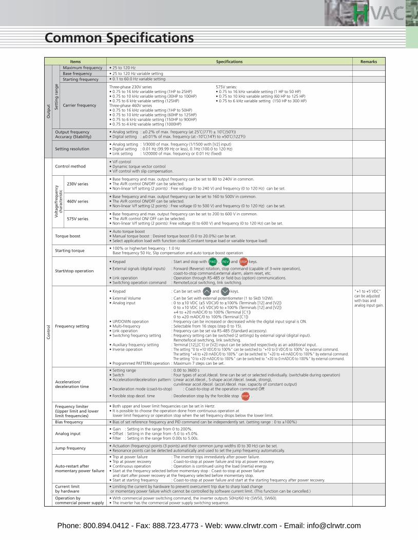
Common Specifications
RemarksItems Specifications
Ou
tpu
t
Sett
ing
ran
ge
Volt
age/
freq
uenc
ych
arac
teri
stic
Co
ntr
ol
Maximum frequency
Output frequencyAccuracy (Stability)
Setting resolution
Control method
Base frequencyStarting frequency
Carrier frequency
230V series
460V series
• 25 to 120 Hz
• 25 to 120 Hz variable setting• 0.1 to 60.0 Hz variable setting
• Analog setting : ±0.2% of max. frequency (at 25˚C(77˚F) ± 10˚C(50˚F))• Digital setting : ±0.01% of max. frequency (at -10˚C(14˚F) to +50˚C(122˚F))
• Analog setting : 1/3000 of max. frequency (1/1500 with [V2] input)• Digital setting : 0.01 Hz (99.99 Hz or less), 0.1Hz (100.0 to 120 Hz)• Link setting : 1/20000 of max. frequency or 0.01 Hz (fixed)
• V/f control• Dynamic torque vector control• V/f control with slip compensation.
• Base frequency and max. output frequency can be set to 80 to 240V in common.• The AVR control ON/OFF can be selected.• Non-linear V/f setting (2 points) : Free voltage (0 to 240 V) and frequency (0 to 120 Hz) can be set.
• Base frequency and max. output frequency can be set to 160 to 500V in common.• The AVR control ON/OFF can be selected.• Non-linear V/f setting (2 points) : Free voltage (0 to 500 V) and frequency (0 to 120 Hz) can be set.
575V series• Base frequency and max. output frequency can be set to 200 to 600 V in common.• The AVR control ON/ OFF can be selected.• Non-linear V/f setting (2 points): Free voltage (0 to 600 V) and frequency (0 to 120 Hz) can be set.
Torque boost• Auto torque boost• Manual torque boost : Desired torque boost (0.0 to 20.0%) can be set.• Select application load with function code.(Constant torque load or variable torque load)
"+1 to +5 VDC"can be adjustedwith bias andanalog input gain.
Starting torque • 100% or higher/set frequency : 1.0 HzBase frequency 50 Hz, Slip compensation and auto torque boost operation
Acceleration/deceleration time
Frequency limiter(Upper limit and lowerlimit frequencies)
Bias frequency
Analog input
• Setting range : 0.00 to 3600 s• Switch : Four types of accel./decel. time can be set or selected individually. (switchable during operation)• Acceleration/deceleration pattern : Linear accel./decel., S-shape accel./decel. (weak, strong),
curvilinear accel./decel. (accel./decel. max. capacity of constant output)• Deceleration mode (coast-to-stop) : Coast-to-stop at the operation command OFF.
• Forcible stop decel. time : Deceleration stop by the forcible stop .
• Both upper and lower limit frequencies can be set in Hertz.• It is possible to choose the operation done from continuous operation at
lower limit frequency or operation stop when the set frequency drops below the lower limit.
• Bias of set reference frequency and PID command can be independently set. (setting range : 0 to ±100%)
• Gain : Setting in the range from 0 to 200%.• Offset : Setting in the range from -5.0 to +5.0%.• Filter : Setting in the range from 0.00s to 5.00s.
Jump frequency • Actuation (frequency) points (3 points) and their common jump widths (0 to 30 Hz) can be set.• Resonance points can be detected automatically and used to set the jump frequency automatically.
Auto-restart aftermomentary power failure
• Trip at power failure : The inverter trips immediately after power failure.• Trip at power recovery : Coast-to-stop at power failure and trip at power recovery.• Continuous operation : Operation is continued using the load (inertia) energy.• Start at the frequency selected before momentary stop : Coast-to-stop at power failure and start after power recovery at the frequency selected before momentary stop.• Start at starting frequency : Coast-to-stop at power failure and start at the starting frequency after power recovery.
• Keypad : Start and stop with , and keys.
• External signals (digital inputs) : Forward (Reverse) rotation, stop command (capable of 3-wire operation), coast-to-stop command,external alarm, alarm reset, etc.
• Link operation : Operation through RS-485 or field bus (option) communications.• Switching operation command : Remote/Local switching, link switching.
• Keypad : Can be set with and keys.
• External Volume : Can be Set with external potentiometer (1 to 5kΩ 1/2W).• Analog input : 0 to ±10 VDC (±5 VDC)/0 to ±100% (Terminals [12] and [V2])
0 to +10 VDC (+5 VDC)/0 to +100% (Terminals [12] and [V2]) +4 to +20 mADC/0 to 100% (Terminal [C1]) 0 to +20 mADC/0 to 100% (Terminal [C1])
• UP/DOWN operation : Frequency can be increased or decreased while the digital input signal is ON.• Multi-frequency : Selectable from 16 steps (step 0 to 15).• Link operation : Frequency can be set via RS-485 (Standard accessory).• Switching frequency setting : Frequency setting can be switched (2 settings) by external signal (digital input).
Remote/local switching, link switching.• Auxiliary frequency setting : Terminal [12],[C1] or [V2] input can be selected respectively as an additional input.• Inverse operation : The setting "0 to +10 VDC/0 to 100%" can be switched to "+10 to 0 VDC/0 to 100%" by external command.
The setting "+4 to +20 mADC/0 to 100%" can be switched to "+20 to +4 mADC/0 to 100%" by external command. The setting "0 to +20 mADC/0 to 100%" can be switched to "+20 to 0 mADC/0 to 100%" by external command.
• Programmed PATTERN operation : Maximum 7 steps can be set.
Three-phase 230V series• 0.75 to 16 kHz variable setting (1HP to 25HP)• 0.75 to 10 kHz variable setting (30HP to 100HP)• 0.75 to 6 kHz variable setting (125HP)Three-phase 460V series• 0.75 to 16 kHz variable setting (1HP to 50HP)• 0.75 to 10 kHz variable setting (60HP to 125HP)• 0.75 to 6 kHz variable setting (150HP to 900HP)• 0.75 to 4 kHz variable setting (1000HP)
575V series:• 0.75 to 16 kHz variable setting (1 HP to 50 HP)• 0.75 to 10 kHz variable setting (60 HP to 125 HP)• 0.75 to 6 kHz variable setting (150 HP to 300 HP)
Start/stop operation
Frequency setting
Current limitby hardware
• Limiting the current by hardware to prevent overcurrent trip due to sharp load change or momentary power failure which cannot be controlled by software current limit. (This function can be cancelled.)
Operation bycommercial power supply
• With commercial power switching command, the inverter outputs 50Hz/60 Hz (SW50, SW60).• The inverter has the commercial power supply switching sequence.
Phone: 800.894.0412 - Fax: 888.723.4773 - Web: www.clrwtr.com - Email: [email protected]
Common Specifications
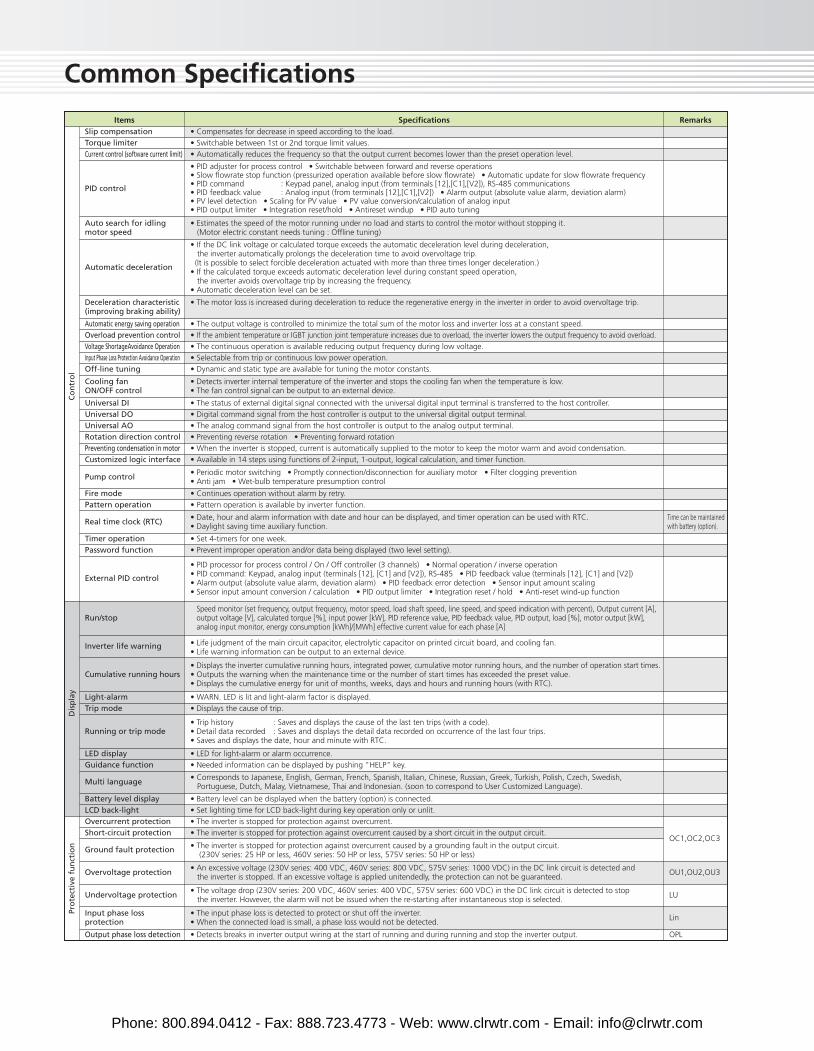
Slip compensation • Compensates for decrease in speed according to the load.
Torque limiter • Switchable between 1st or 2nd torque limit values.
Current control (software current limit) • Automatically reduces the frequency so that the output current becomes lower than the preset operation level.
RemarksItems Specifications
Co
ntr
ol
Dis
pla
y
Deceleration characteristic(improving braking ability)
• The motor loss is increased during deceleration to reduce the regenerative energy in the inverter in order to avoid overvoltage trip.
Automatic energy saving operation • The output voltage is controlled to minimize the total sum of the motor loss and inverter loss at a constant speed.
Overload prevention control • If the ambient temperature or IGBT junction joint temperature increases due to overload, the inverter lowers the output frequency to avoid overload.
Voltage ShortageAvoidance Operation • The continuous operation is available reducing output frequency during low voltage.
Input Phase Loss Protection Avoidance Operation • Selectable from trip or continuous low power operation.
Off-line tuning • Dynamic and static type are available for tuning the motor constants.
Universal DI • The status of external digital signal connected with the universal digital input terminal is transferred to the host controller.
Universal DO • Digital command signal from the host controller is output to the universal digital output terminal.
Universal AO • The analog command signal from the host controller is output to the analog output terminal.
Rotation direction control • Preventing reverse rotation • Preventing forward rotation
Preventing condensation in motorCustomized logic interface
• When the inverter is stopped, current is automatically supplied to the motor to keep the motor warm and avoid condensation.
• Available in 14 steps using functions of 2-input, 1-output, logical calculation, and timer function.
Fire mode • Continues operation without alarm by retry.
Pattern operation • Pattern operation is available by inverter function.
Timer operation • Set 4-timers for one week.
Password function • Prevent improper operation and/or data being displayed (two level setting).
Light-alarm • WARN. LED is lit and light-alarm factor is displayed.
Trip mode • Displays the cause of trip.
LED display • LED for light-alarm or alarm occurrence.
Running or trip mode• Trip history : Saves and displays the cause of the last ten trips (with a code).• Detail data recorded : Saves and displays the detail data recorded on occurrence of the last four trips.• Saves and displays the date, hour and minute with RTC.
Cumulative running hours• Displays the inverter cumulative running hours, integrated power, cumulative motor running hours, and the number of operation start times.• Outputs the warning when the maintenance time or the number of start times has exceeded the preset value.• Displays the cumulative energy for unit of months, weeks, days and hours and running hours (with RTC).
Inverter life warning • Life judgment of the main circuit capacitor, electrolytic capacitor on printed circuit board, and cooling fan.• Life warning information can be output to an external device.
Run/stop Speed monitor (set frequency, output frequency, motor speed, load shaft speed, line speed, and speed indication with percent), Output current [A], output voltage [V], calculated torque [%], input power [kW], PID reference value, PID feedback value, PID output, load [%], motor output [kW], analog input monitor, energy consumption [kWh]/[MWh] effective current value for each phase [A]
External PID control
• PID processor for process control / On / Off controller (3 channels) • Normal operation / inverse operation• PID command: Keypad, analog input (terminals [12], [C1] and [V2]), RS-485 • PID feedback value (terminals [12], [C1] and [V2])• Alarm output (absolute value alarm, deviation alarm) • PID feedback error detection • Sensor input amount scaling• Sensor input amount conversion / calculation • PID output limiter • Integration reset / hold • Anti-reset wind-up function
Pump control • Periodic motor switching • Promptly connection/disconnection for auxiliary motor • Filter clogging prevention• Anti jam • Wet-bulb temperature presumption control
Cooling fanON/OFF control
• Detects inverter internal temperature of the inverter and stops the cooling fan when the temperature is low.• The fan control signal can be output to an external device.
Automatic deceleration
• If the DC link voltage or calculated torque exceeds the automatic deceleration level during deceleration, the inverter automatically prolongs the deceleration time to avoid overvoltage trip.(It is possible to select forcible deceleration actuated with more than three times longer deceleration.)
• If the calculated torque exceeds automatic deceleration level during constant speed operation,the inverter avoids overvoltage trip by increasing the frequency.
• Automatic deceleration level can be set.
Auto search for idlingmotor speed
• Estimates the speed of the motor running under no load and starts to control the motor without stopping it.(Motor electric constant needs tuning : Offline tuning)
PID control
• PID adjuster for process control • Switchable between forward and reverse operations• Slow flowrate stop function (pressurized operation available before slow flowrate) • Automatic update for slow flowrate frequency• PID command : Keypad panel, analog input (from terminals [12],[C1],[V2]), RS-485 communications• PID feedback value : Analog input (from terminals [12],[C1],[V2]) • Alarm output (absolute value alarm, deviation alarm)• PV level detection • Scaling for PV value • PV value conversion/calculation of analog input• PID output limiter • Integration reset/hold • Antireset windup • PID auto tuning
Real time clock (RTC) • Date, hour and alarm information with date and hour can be displayed, and timer operation can be used with RTC.• Daylight saving time auxiliary function.
Time can be maintained with battery (option).
Pro
tect
ive
fun
ctio
n
Guidance function • Needed information can be displayed by pushing "HELP" key.
Battery level display • Battery level can be displayed when the battery (option) is connected.
LCD back-light • Set lighting time for LCD back-light during key operation only or unlit.
OC1,OC2,OC3
OU1,OU2,OU3
LU
Lin
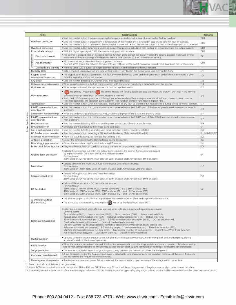
Overcurrent protection • The inverter is stopped for protection against overcurrent.
Short-circuit protection • The inverter is stopped for protection against overcurrent caused by a short circuit in the output circuit.
Ground fault protection • The inverter is stopped for protection against overcurrent caused by a grounding fault in the output circuit. (230V series: 25 HP or less, 460V series: 50 HP or less, 575V series: 50 HP or less)
Input phase loss protection
• The input phase loss is detected to protect or shut off the inverter.• When the connected load is small, a phase loss would not be detected.
Undervoltage protection • The voltage drop (230V series: 200 VDC, 460V series: 400 VDC, 575V series: 600 VDC) in the DC link circuit is detected to stop the inverter. However, the alarm will not be issued when the re-starting after instantaneous stop is selected.
Overvoltage protection • An excessive voltage (230V series: 400 VDC, 460V series: 800 VDC, 575V series: 1000 VDC) in the DC link circuit is detected and the inverter is stopped. If an excessive voltage is applied unitendedly, the protection can not be guaranteed.
Multi language • Corresponds to Japanese, English, German, French, Spanish, Italian, Chinese, Russian, Greek, Turkish, Polish, Czech, Swedish, Portuguese, Dutch, Malay, Vietnamese, Thai and Indonesian. (soon to correspond to User Customized Language).
OPLOutput phase loss detection • Detects breaks in inverter output wiring at the start of running and during running and stop the inverter output.
Phone: 800.894.0412 - Fax: 888.723.4773 - Web: www.clrwtr.com - Email: [email protected]
OH3
RemarksItems Specifications
Pro
tect
ive
fun
ctio
n
Mot
or p
rote
ctio
n
Er1
Er2
Er3
Er4
Er5
Er6
Er7
Er8
ErF
ErH
Err
CoF
ECL
rLo
FoL
ECF
PV1,PV2,PVA,PVb,PVC
ErP
OH1
OLU
OH2
OL1
OH4
Overload protection • Stop the inverter output detecting a switching element temperature calculated with cooling fin temperature and the output current.
External alarm input • With the digital input signal (THR), the inverter is stopped with an alarm.
Memory error • Data is checked upon power-on and data writing to detect any fault in the memory and stop the inverter if any.
CPU error • Stop the inverter detecting a CPU error or LSI error caused by noise.
Option communications error • When an option is used, a fault of communication with the inverter main body is detected to stop the inverter.
Option error • When an option is used, the option detects a fault to stop the inverter.
Tuning error • Stop the inverter output when tuning failure, interruption or any fault as a result of tuning is detected during tuning for motor constant.
Data save error upon undervoltage • When the undervoltage protection occurred, an alarm is displayed if the data is not properly saved.
Hardware error • Stop the inverter detecting a LSI error on the power printed circuit board caused by noise.
Simulation error • Simulated alarm is output by the keypad panel operation.
Current input wire break detection • Stop the inverter detecting an analog wire break detection (enable / disable selectable).
PID feedback error detection • Stop the inverter output detecting a PID feedback line break. (Selectable valid/invalid.)
Customized logic error detection • Alarm is output detecting a customized logic setting error.
Anti jam protection • Display the error detecting the starting failure due to overcurrent.
Filter clogging prevention • Display the error detecting the overload during PID control.
Enable circuit failure detection • Diagnose the enable circuit condition and stop the inverter output detecting the circuit failure.
EFGround fault protection
• Detects the zero-phase current in the output power, protects the inverter from overcurrent causedby a ground fault in the output circuit, and stops the inverter.For inverters of:230V series of 30HP or above, 460V series of 60HP or above and 575V series of 60HP or above.
FUSFuse blown• Detects a break of the main circuit fuse in the inverter and stops the inverter.
For inverters of:230V series of 125HP, 460V series of 150HP or above and 575V series of 200HP or above.
PbFCharger circuit error• Detects a charger circuit error and stops the inverter.
For inverters of:230V series of 30HP or above, 460V series of 60HP or above and 575V series of 60HP or above.
FALDC fan locked
• Failure of the air circulation DC fan inside the inverter.For inverters of:230V series of 75HP or above (IP00), 30HP or above (IP21) and 7.5HP or above (IP55)460V series of 150HP or above (IP00), 60HP or above (IP21) and 15HP or above (IP55)575V series of 200HP or above (IP00), 60HP or above (IP21) and 15HP or above (IP55)
Surge protection • The inverter is protected against surge voltages occuring between the main circuit power line and ground.
Command loss detected • A loss (breaking, etc.) of the frequency command is detected to output an alarm and the operation continues at the preset frequency (set at a ratio to the frequency before detection).
Momentary power failure protection • If restart upon momentary power failure is selected, the inverter restarts upon recovery of the voltage within the set time.
Retry function • When the motor is tripped and stopped, this function automatically resets the tripping state and restarts operation. (Retry times, waiting time for reset, corresponding trip for retry and retry available time can be set. By using communication the times of the restarting can be monitored.
Stall prevention • Operates when the inverter output current is higher than the instantaneous overcurrent limiting level, and avoids tripping, duringacceleration and constant speed operation.
Light-alarm (warning)
• Light- alarm is displayed when alarm or warning set as light-alarm is occurred (operation continues). Covered alarms :External alarm (OH2), Inverter overheat (OH3), Motor overheat (OH4), Motor overload (OL1),Keypad panel communication error (Er2), Optional communication error (Er4), Option error (Er5),RS-485 communication error (port 1)(Er8), RS-485 communication error (port 2)(ErP), DC fan lock detected,Overload early warning (for motor), Heatsink overheat early warning,Life early warning (DC link bus capacitor, electrolytic capacitor on printed circuit board, cooling fan),Reference command loss detected, PID warning output, Low torque detected, Thermistor detection (PTC),Machine life (cumulative motor run time error), Machine life (number of startups error), Current Input Wire Break Detection,PID feedback error detection, Low battery warning, Date&time information lost
Alarm relay output(for any fault)
• The inverter outputs a relay contact signal when the inverter issues an alarm and stops the inverter output.
• The alarm stop state is reset by pressing the key or by the digital input signal (RST).
RS-485 communicationserror (port2)
• Stop the inverter output if a communication error is detected when the RS-485 port of [DX+]/[DX-] terminals is used to communicate with a network.
RS-485 communicationserror (port1)
• Stop the inverter output if a communication error is detected when the RS-485 port of the keypad panel is used to communicate with a network.
Operation error
• key priority : Pressing the key on the keypad will forcibly decelerate, stop the motor and display "Er6" even if the running
command through signal input or communication is selected.• Start check : If the running command is being input when switching the running command method from power-on, alarm reset or the linked operation, the operation starts suddenly. This function prohibits running and displays "Er6".
Keypad panelcommunications error
• The keypad panel detects a communication fault between the keypad panel and the inverter main body if the run command is given from the keypad and stops the inverter.
PTC thermistor • PTC thermistor input stops the inverter to protect the motor.Connect a PTC thermistor between terminal [C1] and [11] and set the switch on control printed circuit board and the function code.
Overload early warning • Warning signal (OL) is output at the predetermined level set in the electronic thermal function.
Electronic thermal • The inverter is stopped with an electronic thermal function set to protect the motor. Protects the general-purpose motor and inverter motor over all frequency range. (The level and thermal time constant (0.5 to 75.0 min) can be set.)
Overheat protection • Stop the inverter output if excessive inner temperature of the inverter unit is detected in case of a cooling fan fault or overload.• Stop the inverter output if a failure in the cooling fan is detected. • Stop the inverter output if a fault in the charging circuit is detected.
• Stop the inverter output if expressive cooling fin temperature is detected in case of a cooling fan fault or overload.
*1 Detection of all circuit failures is not guaranteed.*2 Alarm (ECF) is occurred when one of the inputs of EN1 or EN2 are OFF (If it exceeds 50 ms, it will be as disagreement.). Recycle power supply in order to reset this alarm.*3 If necessary, connect a digital output of the inverter assigned to function DECF to the reset input of an upper safety relay unit, in order to turn the Enable command OFF and shut down the inverter output.
Phone: 800.894.0412 - Fax: 888.723.4773 - Web: www.clrwtr.com - Email: [email protected]
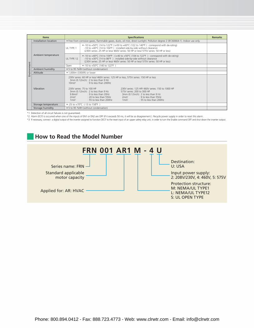
How to Read the Model Number
FRN 001 AR1 M - 4 U
Series name: FRN
Standard applicablemotor capacity
Applied for: AR: HVAC
Input power supply:2: 208V/230V, 4: 460V, 5: 575V
Destination:U: USA
Protection structure:M: NEMA/UL TYPE1L: NEMA/UL TYPE12S: UL OPEN TYPE
RemarksItems Specifications
Envi
ron
men
t
Ambient humidity • 5 to 95 %RH (without condensation)
Altitude • 1,000m (3300ft) or lower
Storage temperature • -25 to +70°C (-13 to 158°F )
Storage humidity • 5 to 95 %RH (without condensation)
Vibration
230V series: 60 HP or less/ 460V series: 125 HP or less, 575V series: 150 HP or less 3mm (0.12inch) : 2 to less than 9 Hz 10m/s2 : 9 to less than 200Hz
230V series: 75 to 100 HP 230V series: 125 HP/ 460V series: 150 to 1000 HP 3mm (0.12inch) : 2 to less than 9 Hz 575V series: 200 to 300 HP 9.8m/s2 : 9 to less than 20Hz 3mm (0.12inch) : 2 to less than 9 Hz 2m/s2 : 20 to less than 55Hz 2m/s2 : 9 to less than 55Hz 1m/s2 : 55 to less than 200Hz 1m/s2 : 55 to less than 200Hz
Installation location • Free from corrosive gases, flammable gases, dusts, oil mist, direct sunlight. Pollution degree 2 (IEC60664-1). Indoor use only.
Ambient temperature
• -10 to +50°C (14 to 122°F ) (+50 to +60°C (122 to 140°F ) : correspond with de-rating)-10 to +40°C (14 to 104°F ) : installed side-by-side without clearance (230V series: 25 HP or less/ 460V series: 50 HP or less/ 575V series: 50 HP or less)
UL TYPE 1
UL TYPE 12
Open
• -10 to +40°C (14 to 104°F ) (+40 to +50°C (104 to 122°F ) : correspond with de-rating)-10 to +30°C (14 to 86°F ) : installed side-by-side without clearance(230V series: 25 HP or less/ 460V series: 50 HP or less/ 575V series: 50 HP or less)
• -10 to +50°C (140 to 122°F )
*1 Detection of all circuit failures is not guaranteed.*2 Alarm (ECF) is occurred when one of the inputs of EN1 or EN2 are OFF (If it exceeds 50 ms, it will be as disagreement.). Recycle power supply in order to reset this alarm.*3 If necessary, connect a digital output of the inverter assigned to function DECF to the reset input of an upper safety relay unit, in order to turn the Enable command OFF and shut down the inverter output.
Phone: 800.894.0412 - Fax: 888.723.4773 - Web: www.clrwtr.com - Email: [email protected]
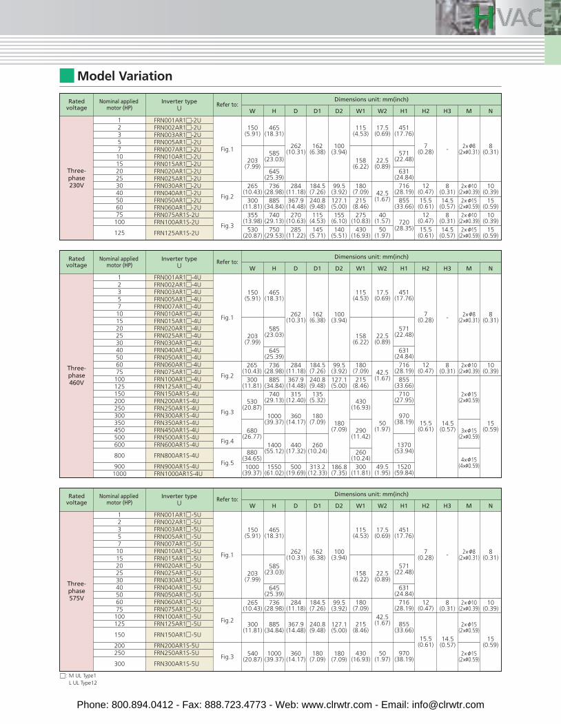
Model Variation
12357101520253040506075100
125
Three-phase230V
Ratedvoltage
Inverter typeU
Nominal applied motor (HP)
Fig.1
Fig.2
Fig.3
150(5.91)
203(7.99)
265(10.43)
300(11.81)
355(13.98)
530(20.87)
465(18.31)
585(23.03)
645(25.39)
736(28.98)
885(34.84)
740(29.13)
750(29.53)
262(10.31)
284(11.18)367.9(14.48)
270(10.63)
285(11.22)
162(6.38)
184.5(7.26)240.8(9.48)115
(4.53)145
(5.71)
115(4.53)
158(6.22)
180(7.09)215
(8.46)275
(10.83)430
(16.93)
17.5(0.69)
22.5(0.89)
42.5(1.67)
40(1.57)
50(1.97)
451(17.76)
571(22.48)
631(24.84)
716(28.19)
855(33.66)
720(28.35)
7(0.28)
12(0.47)15.5
(0.61)12
(0.47)15.5
(0.61)
W W1 W2H H1 H2
2× 8(2× 0.31)
2× 10(2× 0.39)2× 15
(2× 0.59)2× 10
(2× 0.39)2× 15
(2× 0.59)
H3
-
8(0.31)14.5(0.57)8
(0.31)14.5(0.57)
M
8(0.31)
10(0.39)
15(0.59)
10(0.39)
15(0.59)
ND D1 D2
Dimensions unit: mm(inch)Refer to:
100(3.94)
Ratedvoltage
Inverter typeU
Nominal applied motor (HP)
Fig.1
Fig.2
Fig.3
Fig.4
Fig.5
150(5.91)
203(7.99)
265(10.43)
300(11.81)
530(20.87)
680(26.77)
880(34.65)1000
(39.37)
465(18.31)
585(23.03)
645(25.39)
736(28.98)
885(34.84)
740(29.13)
1000(39.37)
585(23.03)
645(25.39)
736(28.98)
885(34.84)
1000(39.37)
1400(55.12)
1550(61.02)
262(10.31)
284(11.18)367.9(14.48)
315(12.40)
360(14.17)
284(11.18)
367.9(14.48)
360(14.17)
440(17.32)
500(19.69)
162(6.38)
184.5(7.26)240.8(9.48)135
(5.32)
180(7.09)
184.5(7.26)
240.8(9.48)
180(7.09)
260(10.24)
313.2(12.33)
115(4.53)
158(6.22)
180(7.09)215
(8.46)
430(16.93)
290(11.42)
158(6.22)
180(7.09)
215(8.46)
430(16.93)
260(10.24)
300(11.81)
17.5(0.69)
22.5(0.89)
42.5(1.67)
50(1.97)
22.5(0.89)
42.5(1.67)
50(1.97)
49.5(1.95)
451(17.76)
571(22.48)
631(24.84)
716(28.19)
855(33.66)
710(27.95)
970(38.19)
571(22.48)
631(24.84)
716(28.19)
855(33.66)
970(38.19)
1370(53.94)
1520(59.84)
7(0.28)
12(0.47)
15.5(0.61)
12(0.47)
15.5(0.61)
W W1 W2H H1 H2
2× 8(2× 0.31)
2× 10(2× 0.39)
2× 15(2× 0.59)
3× 15(2× 0.59)
2× 10(2× 0.39)
2× 15(2× 0.59)
2× 15(2× 0.59)
4× 15(4× 0.59)
H3
-
8(0.31)
14.5(0.57)
8(0.31)
14.5(0.57)
M
8(0.31)
10(0.39)
15(0.59)
10(0.39)
15(0.59)
ND D1 D2
Dimensions unit: mm(inch)Refer to:
100(3.94)
99.5(3.92)127.1(5.00)
180(7.09)
99.5(3.92)
127.1(5.00)
180(7.09)
186.8(7.35)
99.5(3.92)127.1(5.00)155
(6.10)140
(5.51)
FRN001AR1 -2UFRN002AR1 -2UFRN003AR1 -2UFRN005AR1 -2UFRN007AR1 -2UFRN010AR1 -2UFRN015AR1 -2UFRN020AR1 -2UFRN025AR1 -2UFRN030AR1 -2UFRN040AR1 -2UFRN050AR1 -2UFRN060AR1 -2UFRN075AR1S-2UFRN100AR1S-2U
FRN125AR1S-2U
12357101520253040506075100125150200250300350450500600
800
9001000
Three-phase460V
FRN001AR1 -4UFRN002AR1 -4UFRN003AR1 -4UFRN005AR1 -4UFRN007AR1 -4UFRN010AR1 -4UFRN015AR1 -4UFRN020AR1 -4UFRN025AR1 -4UFRN030AR1 -4UFRN040AR1 -4UFRN050AR1 -4UFRN060AR1 -4UFRN075AR1 -4UFRN100AR1 -4UFRN125AR1 -4UFRN150AR1S-4UFRN200AR1S-4UFRN250AR1S-4UFRN300AR1S-4UFRN350AR1S-4UFRN450AR1S-4UFRN500AR1S-4UFRN600AR1S-4U
FRN800AR1S-4U
FRN900AR1S-4UFRN1000AR1S-4U
Ratedvoltage
Inverter typeU
Nominal applied motor (HP)
Fig.1
Fig.2
Fig.3
150(5.91)
203(7.99)
265(10.43)
300(11.81)
540(20.87)
465(18.31)
262(10.31)
162(6.38)
115(4.53)
17.5(0.69)
451(17.76)
7(0.28)
W W1 W2H H1 H2
2× 8(2× 0.31)
H3
-
M
8(0.31)
ND D1 D2
Dimensions unit: mm(inch)Refer to:
100(3.94)
12357101520253040506075100125
150
200250
300
Three-phase575V
FRN001AR1 -5UFRN002AR1 -5UFRN003AR1 -5UFRN005AR1 -5UFRN007AR1 -5UFRN010AR1 -5UFRN015AR1 -5UFRN020AR1 -5UFRN025AR1 -5UFRN030AR1 -5UFRN040AR1 -5UFRN050AR1 -5UFRN060AR1 -5UFRN075AR1 -5UFRN100AR1 -5UFRN125AR1 -5U
FRN150AR1 -5U
FRN200AR1S-5UFRN250AR1S-5U
FRN300AR1S-5U
: M UL Type1L UL Type12
Phone: 800.894.0412 - Fax: 888.723.4773 - Web: www.clrwtr.com - Email: [email protected]
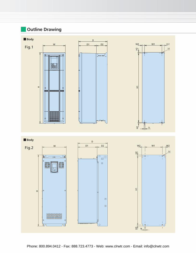
W2 W1
H2
H1H
H2
W
D
D1 D2
W2 W2
N
W1
H3
H1
H2
H
W
D
D1 D2
W2 W2
M
W1
NH2
H1H
H2
W
D
D1 D2
W2 W2
N
W1
H3
H1
H2
H
W
D
D1 D2
M
Outline Drawing
Body
Body
Fig.1
Fig.2
Phone: 800.894.0412 - Fax: 888.723.4773 - Web: www.clrwtr.com - Email: [email protected]
M
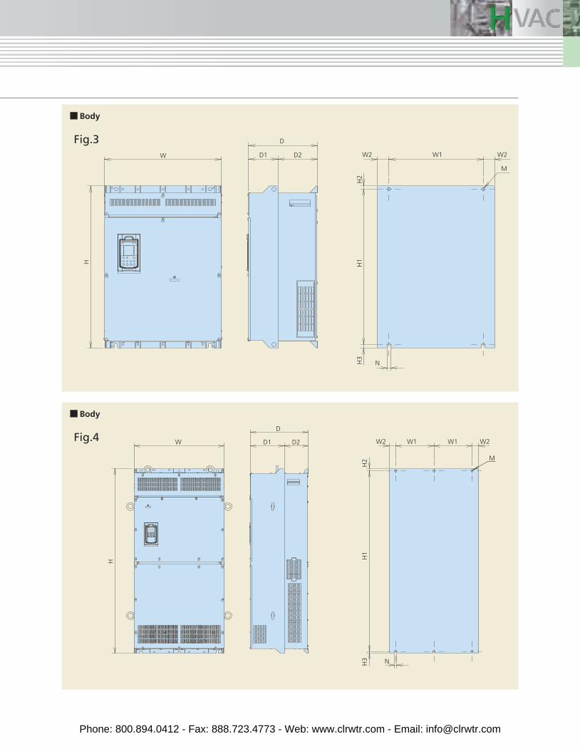
Body
Fig.3
W2 W2W1 W1
H1
H3
H2
H
W
D
D1 D2
N
Body
Fig.4
W2 W2
N
M
W1
H3
H1
H2
D
D1 D2
H
W
Phone: 800.894.0412 - Fax: 888.723.4773 - Web: www.clrwtr.com - Email: [email protected]
M
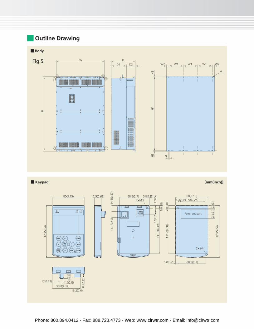
Outline Drawing
W2 W2
N
W1 W1 W1
H3
H1
D
D1 D2
H
W
H2
Body
Fig.5
7(0.
28)
80(3.15) 17.5(0.69) 68.5(2.7)2×M3
5.8(0.23)
8.2(
0.32
)
7(0.
28)
111.
6(4.
39)
111.
6(4.
39)
13.7
(0.5
4)
128(
5.04
)
80(3.15)58(2.28)
Panel cut part
8.2(0.32)
15.1
(0.5
9)14
.6(0
.57)
23(0
.91)
128(
5.04
)
2.5(
0.1)
5.8(0.23) 68.5(2.7)
15.2(0.6)
53.8(2.12)11.7(0.46)17(0.67) 11.
4(0.45
)
8.1(
0.32
)
Keypad [mm(inch)]
2× 4
Phone: 800.894.0412 - Fax: 888.723.4773 - Web: www.clrwtr.com - Email: [email protected]
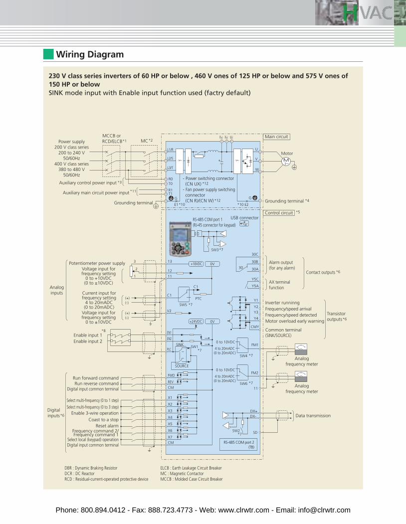
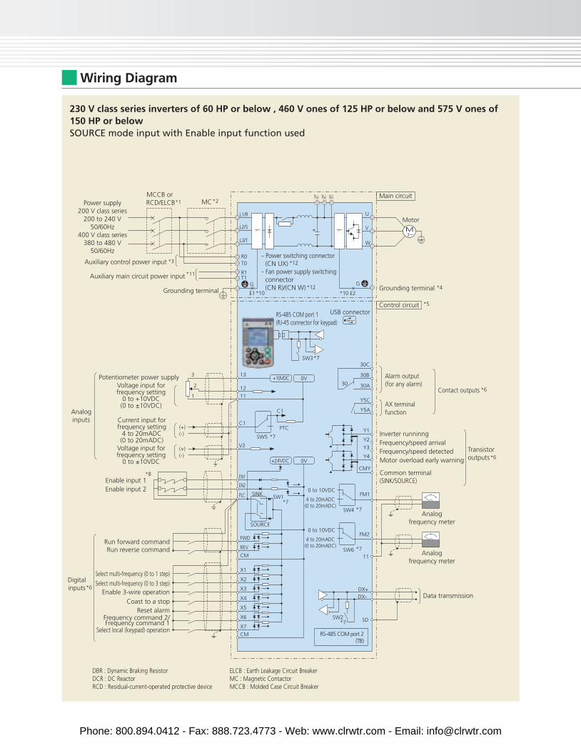
Wiring Diagram
230 V class series inverters of 60 HP or below , 460 V ones of 125 HP or below and 575 V ones of 150 HP or below SINK mode input with Enable input function used (factry default)
Auxiliary control power input
Power supply200 V class series
200 to 240 V50/60Hz
400 V class series380 to 480 V
50/60Hz
Grounding terminal
- Power switching connector (CN UX)- Fan power supply switching connector (CN R)/(CN W)
Main circuit
Grounding terminal
MCCB or RCD/ELCB MC
*4
*3
*1 *2
Auxiliary main circuit power input *11
*12
*12
M
L1/R
L2/S
L3/T
R0T0
R1T1
G
E1 E2*10 *10
G
U
V
W
P(+) P(+) N(-)
+
Motor
Alarm output(for any alarm)
AX terminalfunction
Inverter runninngFrequency/speed arrivalFrequency/speed detectedMotor overload early warning
Common terminal(SINK/SOURCE)
Data transmission
RS-485 COM port 2(TB)
RS-485 COM port 1(RJ-45 connector for keypad)
Analogfrequency meter
Analogfrequency meter
Voltage input forfrequency setting
0 to ±10VDC
Voltage input forfrequency setting
0 to +10VDC(0 to ±10VDC)
0 to 10VDC
Current input forfrequency setting
4 to 20mADC(0 to 20mADC)
4 to 20mADC(0 to 20mADC)
0 to 10VDC
4 to 20mADC(0 to 20mADC)
Control circuit
Potentiometer power supply
*5
*7
*7
*7
*7
*6
Enable input 1Enable input 2
Digital input common terminalRun reverse command
Select multi-frequency (0 to 1 step)
Select multi-frequency (0 to 3 step)Enable 3-wire operation
Coast to a stopReset alarm
Select local (keypad) operationDigital input common terminal
Frequency command 2/Frequency command 1
FM1
CMY
Y2
Y1
30C
30B
30A
Y5C
Y5A
30
Y3
Y4
FM2
11
SD
*8
SW4
SW6
SW3
*6
*6
SW2
DX+DX-
USB connector
Contact outputs
Transistor outputs
Run forward command
Digitalinputs
Analoginputs
0V+24VDC
0V+10VDC13
12
111
3
2
*7
*7
REV
CM
CM
X1
X2
X3
X4
X5
X6
X7
FWD
EN1
PTC
V2
C1
C1
SW5
EN2
PLCSW1
SOURCE
SINK
(+)(-)
(+)(-)
DBR : Dynamic Braking ResistorDCR : DC ReactorRCD : Residual-current-operated protective device
ELCB : Earth Leakage Circuit BreakerMC : Magnetic ContactorMCCB : Molded Case Circuit Breaker
Phone: 800.894.0412 - Fax: 888.723.4773 - Web: www.clrwtr.com - Email: [email protected]
Wiring Diagram
Inverter runninngFrequency/speed arrivalFrequency/speed detectedMotor overload early warning
Common terminal(SINK/SOURCE)
Data transmission
RS-485 COM port 2(TB)
RS-485 COM port 1(RJ-45 connector for keypad)
Analogfrequency meter
Analogfrequency meter
0V+24VDC
0V+10VDC
0 to 10VDC
4 to 20mADC(0 to 20mADC)
0 to 10VDC
4 to 20mADC(0 to 20mADC)
Control circuit
13
12
111
3
2
*5
*7
*7
*7*7
*7
*7
Enable input 1Enable input 2
Run reverse command
Select multi-frequency (0 to 1 step)
Select multi-frequency (0 to 3 step)Enable 3-wire operation
Coast to a stopReset alarm
Select local (keypad) operation
Frequency command 2/Frequency command 1
REV
CM
CM
X1
X2
X3
X4
X5
X6
X7
FWD
EN1
PTC
FM1
CMY
Y2
Y1
30C
30B
30A
Y5C
Y5A
30
Y3
Y4
FM2
11
SD
V2
C1
C1
SW5
EN2
PLC
*8
SW1
SOURCE
SINK
SW4
SW6
SW3
SW2
(+)(-)
(+)(-)
DX+DX-
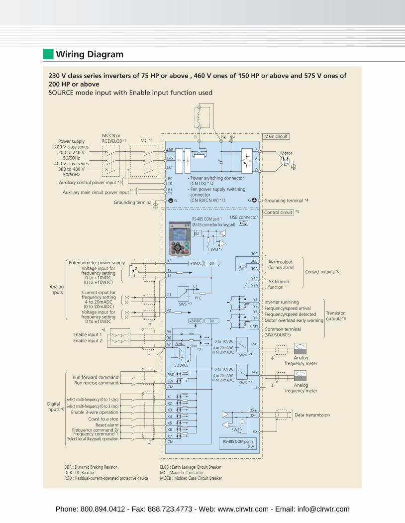
230 V class series inverters of 60 HP or below , 460 V ones of 125 HP or below and 575 V ones of 150 HP or belowSOURCE mode input with Enable input function used
Run forward command
DBR : Dynamic Braking ResistorDCR : DC ReactorRCD : Residual-current-operated protective device
ELCB : Earth Leakage Circuit BreakerMC : Magnetic ContactorMCCB : Molded Case Circuit Breaker
Voltage input forfrequency setting
0 to ±10VDC
Voltage input forfrequency setting
0 to +10VDC(0 to ±10VDC)
Current input forfrequency setting
4 to 20mADC(0 to 20mADC)
Potentiometer power supply
Analoginputs
Auxiliary control power input
Power supply200 V class series
200 to 240 V50/60Hz
400 V class series380 to 480 V
50/60Hz- Power switching connector (CN UX)- Fan power supply switching connector (CN R)/(CN W)
Main circuit
Grounding terminal
MCCB or RCD/ELCB MC
*3
*1 *2
Auxiliary main circuit power input *11
*12
*12
M
L1/R
L2/S
L3/T
R0T0
R1T1
G
E1 E2*10 *10
G
U
V
W
P(+) P(+) N(-)
+
Motor
USB connector
Alarm output(for any alarm)
AX terminalfunction
*6Contact outputs
*6Transistor outputs
*6Digitalinputs
Grounding terminal *4
Phone: 800.894.0412 - Fax: 888.723.4773 - Web: www.clrwtr.com - Email: [email protected]
MC*2
M
Auxiliary control power input- Power switching connector (CN UX)- Fan power supply switching connector (CN R)/(CN W)
Main circuitMCCB or RCD/ELCB
L1/R
L2/S
L3/T
R0T0
R1T1
G G
U
V
W
*3
*1
Auxiliary main circuit power input *11
*12
*12
P(+) N(-)
+
P1
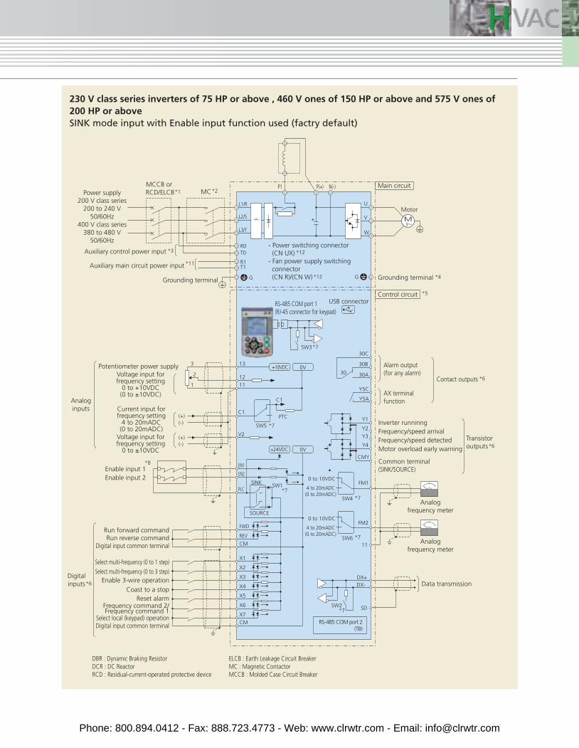
230 V class series inverters of 75 HP or above , 460 V ones of 150 HP or above and 575 V ones of 200 HP or above SINK mode input with Enable input function used (factry default)
Motor
Alarm output(for any alarm)
AX terminalfunction
Inverter runninngFrequency/speed arrivalFrequency/speed detectedMotor overload early warning
Common terminal(SINK/SOURCE)
Data transmission
RS-485 COM port 2(TB)
RS-485 COM port 1(RJ-45 connector for keypad)
Analogfrequency meter
Analogfrequency meter
Voltage input forfrequency setting
0 to ±10VDC
Voltage input forfrequency setting
0 to +10VDC(0 to ±10VDC)
0 to 10VDC
Current input forfrequency setting
4 to 20mADC(0 to 20mADC)
4 to 20mADC(0 to 20mADC)
0 to 10VDC
4 to 20mADC(0 to 20mADC)
Control circuit
Potentiometer power supply
*5
*7
*7
*7
*7
*6
Enable input 1Enable input 2
Digital input common terminalRun reverse command
Select multi-frequency (0 to 1 step)
Select multi-frequency (0 to 3 step)Enable 3-wire operation
Coast to a stopReset alarm
Select local (keypad) operationDigital input common terminal
Frequency command 2/Frequency command 1
FM1
CMY
Y2
Y1
30C
30B
30A
Y5C
Y5A
30
Y3
Y4
FM2
11
SD
*8
SW4
SW6
SW3
*6
*6
SW2
DX+DX-
USB connector
Contact outputs
Transistor outputs
Run forward command
Digitalinputs
Analoginputs
0V+24VDC
0V+10VDC13
12
111
3
2
*7
*7
REV
CM
CM
X1
X2
X3
X4
X5
X6
X7
FWD
EN1
PTC
V2
C1
C1
SW5
EN2
PLCSW1
SOURCE
SINK
(+)(-)
(+)(-)
DBR : Dynamic Braking ResistorDCR : DC ReactorRCD : Residual-current-operated protective device
ELCB : Earth Leakage Circuit BreakerMC : Magnetic ContactorMCCB : Molded Case Circuit Breaker
Power supply200 V class series
200 to 240 V50/60Hz
400 V class series380 to 480 V
50/60Hz
Grounding terminal Grounding terminal *4
Phone: 800.894.0412 - Fax: 888.723.4773 - Web: www.clrwtr.com - Email: [email protected]
Wiring Diagram
230 V class series inverters of 75 HP or above , 460 V ones of 150 HP or above and 575 V ones of 200 HP or above SOURCE mode input with Enable input function used
MC*2
M
Auxiliary control power input- Power switching connector (CN UX)- Fan power supply switching connector (CN R)/(CN W)
Main circuitMCCB or RCD/ELCB
L1/R
L2/S
L3/T
R0T0
R1T1
G G
U
V
W
*3
*1
Auxiliary main circuit power input *11
*12
*12
P(+) N(-)
+
P1
Motor
Power supply200 V class series
200 to 240 V50/60Hz
400 V class series380 to 480 V
50/60Hz
Grounding terminal
Inverter runninngFrequency/speed arrivalFrequency/speed detectedMotor overload early warning
Common terminal(SINK/SOURCE)
Data transmission
RS-485 COM port 2(TB)
RS-485 COM port 1(RJ-45 connector for keypad)
Analogfrequency meter
Analogfrequency meter
0V+24VDC
0V+10VDC
0 to 10VDC
4 to 20mADC(0 to 20mADC)
0 to 10VDC
4 to 20mADC(0 to 20mADC)
Control circuit
13
12
111
3
2
*5
*7
*7
*7*7
*7
*7
Enable input 1Enable input 2
Run reverse command
Select multi-frequency (0 to 1 step)
Select multi-frequency (0 to 3 step)Enable 3-wire operation
Coast to a stopReset alarm
Select local (keypad) operation
Frequency command 2/Frequency command 1
REV
CM
CM
X1
X2
X3
X4
X5
X6
X7
FWD
EN1
PTC
FM1
CMY
Y2
Y1
30C
30B
30A
Y5C
Y5A
30
Y3
Y4
FM2
11
SD
V2
C1
C1
SW5
EN2
PLC
*8
SW1
SOURCE
SINK
SW4
SW6
SW3
SW2
(+)(-)
(+)(-)
DX+DX-
Run forward command
DBR : Dynamic Braking ResistorDCR : DC ReactorRCD : Residual-current-operated protective device
ELCB : Earth Leakage Circuit BreakerMC : Magnetic ContactorMCCB : Molded Case Circuit Breaker
Voltage input forfrequency setting
0 to ±10VDC
Voltage input forfrequency setting
0 to +10VDC(0 to ±10VDC)
Current input forfrequency setting
4 to 20mADC(0 to 20mADC)
Potentiometer power supply
Analoginputs
USB connector
Alarm output(for any alarm)
AX terminalfunction
*6Contact outputs
*6Transistor outputs
*6Digitalinputs
Grounding terminal *4
Phone: 800.894.0412 - Fax: 888.723.4773 - Web: www.clrwtr.com - Email: [email protected]
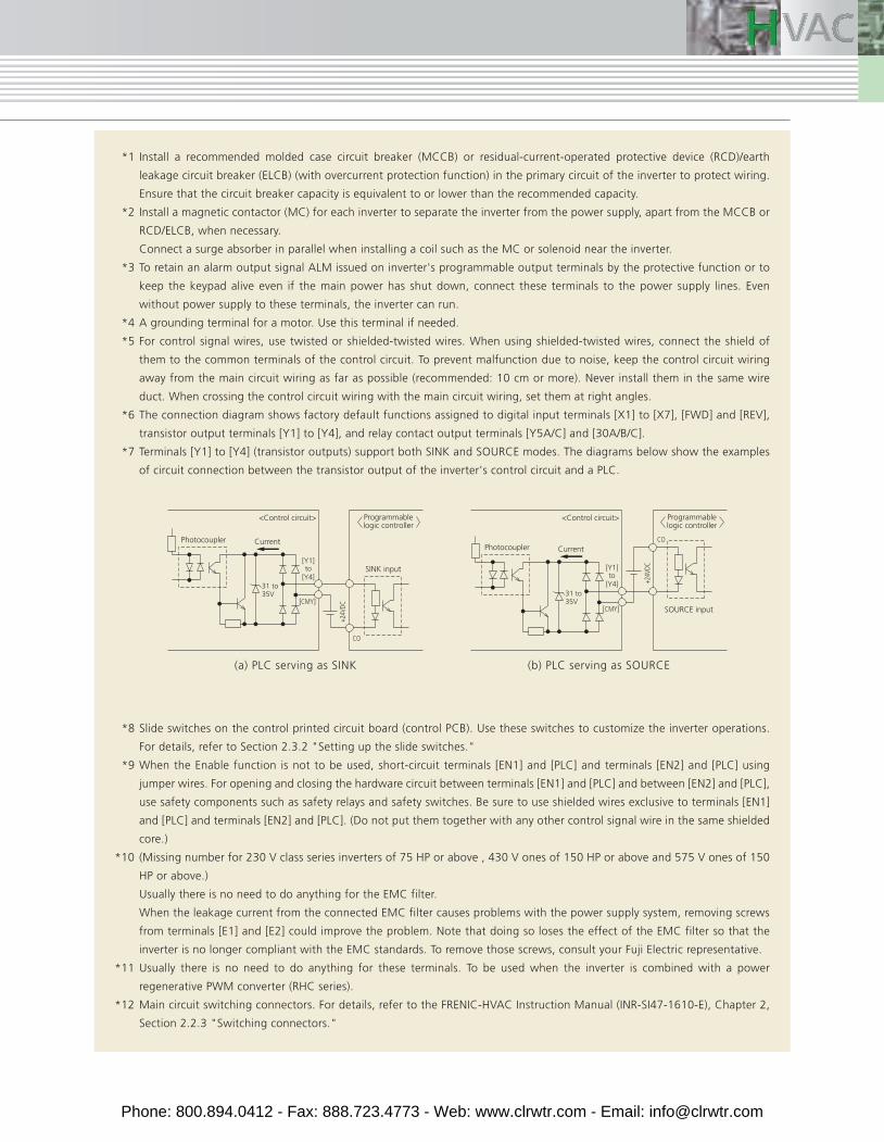
*1 Install a recommended molded case circuit breaker (MCCB) or residual-current-operated protective device (RCD)/earth
leakage circuit breaker (ELCB) (with overcurrent protection function) in the primary circuit of the inverter to protect wiring.
Ensure that the circuit breaker capacity is equivalent to or lower than the recommended capacity.
*2 Install a magnetic contactor (MC) for each inverter to separate the inverter from the power supply, apart from the MCCB or
RCD/ELCB, when necessary.
Connect a surge absorber in parallel when installing a coil such as the MC or solenoid near the inverter.
*3 To retain an alarm output signal ALM issued on inverter's programmable output terminals by the protective function or to
keep the keypad alive even if the main power has shut down, connect these terminals to the power supply lines. Even
without power supply to these terminals, the inverter can run.
*4 A grounding terminal for a motor. Use this terminal if needed.
*5 For control signal wires, use twisted or shielded-twisted wires. When using shielded-twisted wires, connect the shield of
them to the common terminals of the control circuit. To prevent malfunction due to noise, keep the control circuit wiring
away from the main circuit wiring as far as possible (recommended: 10 cm or more). Never install them in the same wire
duct. When crossing the control circuit wiring with the main circuit wiring, set them at right angles.
*6 The connection diagram shows factory default functions assigned to digital input terminals [X1] to [X7], [FWD] and [REV],
transistor output terminals [Y1] to [Y4], and relay contact output terminals [Y5A/C] and [30A/B/C].
*7 Terminals [Y1] to [Y4] (transistor outputs) support both SINK and SOURCE modes. The diagrams below show the examples
of circuit connection between the transistor output of the inverter's control circuit and a PLC.
*8 Slide switches on the control printed circuit board (control PCB). Use these switches to customize the inverter operations.
For details, refer to Section 2.3.2 "Setting up the slide switches."
*9 When the Enable function is not to be used, short-circuit terminals [EN1] and [PLC] and terminals [EN2] and [PLC] using
jumper wires. For opening and closing the hardware circuit between terminals [EN1] and [PLC] and between [EN2] and [PLC],
use safety components such as safety relays and safety switches. Be sure to use shielded wires exclusive to terminals [EN1]
and [PLC] and terminals [EN2] and [PLC]. (Do not put them together with any other control signal wire in the same shielded
core.)
*10 (Missing number for 230 V class series inverters of 75 HP or above , 430 V ones of 150 HP or above and 575 V ones of 150
HP or above.)
Usually there is no need to do anything for the EMC filter.
When the leakage current from the connected EMC filter causes problems with the power supply system, removing screws
from terminals [E1] and [E2] could improve the problem. Note that doing so loses the effect of the EMC filter so that the
inverter is no longer compliant with the EMC standards. To remove those screws, consult your Fuji Electric representative.
*11 Usually there is no need to do anything for these terminals. To be used when the inverter is combined with a power
regenerative PWM converter (RHC series).
*12 Main circuit switching connectors. For details, refer to the FRENIC-HVAC Instruction Manual (INR-SI47-1610-E), Chapter 2,
Section 2.2.3 "Switching connectors."
(a) PLC serving as SINK (b) PLC serving as SOURCE
SOURCE input
CO
+24V
DC[Y1]
[Y4] to
31 to35V
[CMY]
Current
<Control circuit>
SINK input
31 to35V
[Y1]
[Y4]
[CMY]
CO
+24V
DC
to
CurrentPhotocoupler
<Control circuit>
Photocoupler
Programmablelogic controller
Programmablelogic controller
Phone: 800.894.0412 - Fax: 888.723.4773 - Web: www.clrwtr.com - Email: [email protected]
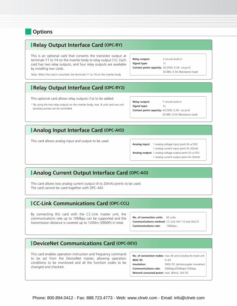
Options
Relay Output Interface Card (OPC-RY)
This is an optional card that converts the transistor output at terminals Y1 to Y4 on the inverter body to relay output (1c). Each card has two relay outputs, and four relay outputs are available by installing two cards.
Note: When the card is mounted, the terminals Y1 to Y4 on the inverter body
Relay output:
Signal type:
Contact point capacity:
2 circuits built-in
1c
AC250V, 0.3A cos =0.
DC48V, 0.5A (Resistance load)
No. of connection nodes:
MAC ID:
Insulation:
Communications rate:
Network consumed power:
max. 64 units (including the master unit)
0~63
500V DC (photocoupler insulation)
500kbps/250kbps/125kbps
max. 80mA, 24V DC
Relay Output Interface Card (OPC-RY2)
This optional card allows relay outputs (1a) to be added.
* By using the two relay outputs on the inverter body, max. 8 units and one unit
(auxiliary pump) can be controlled.
Relay output:
Signal type:
Contact point capacity:
7 circuits built-in
1a
AC250V, 0.3A cos =0.
DC48V, 0.5A (Resistance load)
No. of connection units:
Communications method:
Communications rate:
42 units
CC-Link Ver1.10 and Ver2.0
156kbps~
Analog Input Interface Card (OPC-AIO)
This card allows analog input and output to be used.Analog input:
Analog output:
1 analog voltage input point (0~±10V)
1 analog current input point (4~20mA)
1 analog voltage output point (0~±10V)
1 analog current output point (4~20mA)
Analog Current Output Interface Card (OPC-AO)
This card allows two analog current output (4 to 20mA) points to be used. The card cannot be used together with OPC-AIO.
CC-Link Communications Card (OPC-CCL)
By connecting this card with the CC-Link master unit, the communications rate up to 10Mbps can be supported and the transmission distance is covered up to 1200m (3900ft) in total.
DeviceNet Communications Card (OPC-DEV)
This card enables operation instruction and frequency command to be set from the DeviceNet master, allowing operation conditions to be monitored and all the function codes to be changed and checked.
Phone: 800.894.0412 - Fax: 888.723.4773 - Web: www.clrwtr.com - Email: [email protected]
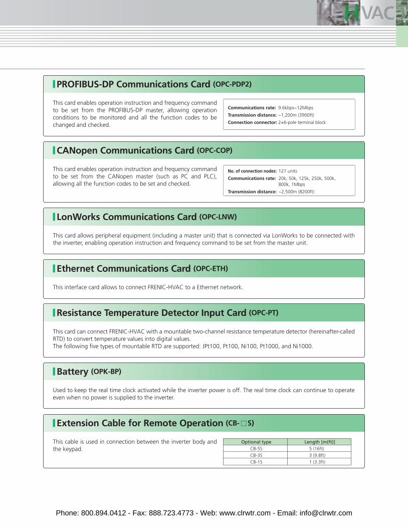
Optional typeCB-5S
CB-3S
CB-1S
Length [m(ft)]
PROFIBUS-DP Communications Card (OPC-PDP2)
This card enables operation instruction and frequency command to be set from the PROFIBUS-DP master, allowing operation conditions to be monitored and all the function codes to be changed and checked.
Communications rate:
Transmission distance:
Connection connector:
9.6kbps~12Mbps
~1,200m (3900ft)
2×6-pole terminal block
CANopen Communications Card (OPC-COP)
This card enables operation instruction and frequency command to be set from the CANopen master (such as PC and PLC), allowing all the function codes to be set and checked.
No. of connection nodes:
Communications rate:
Transmission distance:
127 units
20k, 50k, 125k, 250k, 500k, 800k, 1Mbps
~2,500m (8200ft)
Extension Cable for Remote Operation (CB- S)
This cable is used in connection between the inverter body and the keypad.
LonWorks Communications Card (OPC-LNW)
This card allows peripheral equipment (including a master unit) that is connected via LonWorks to be connected with the inverter, enabling operation instruction and frequency command to be set from the master unit.
Battery (OPK-BP)
Used to keep the real time clock activated while the inverter power is off. The real time clock can continue to operate even when no power is supplied to the inverter.
Ethernet Communications Card (OPC-ETH)
Resistance Temperature Detector Input Card (OPC-PT)
This interface card allows to connect FRENIC-HVAC to a Ethernet network.
This card can connect FRENIC-HVAC with a mountable two-channel resistance temperature detector (hereinafter-called RTD) to convert temperature values into digital values. The following five types of mountable RTD are supported: JPt100, Pt100, Ni100, Pt1000, and Ni1000.
5 (16ft)
3 (9.8ft)
1 (3.3ft)
Phone: 800.894.0412 - Fax: 888.723.4773 - Web: www.clrwtr.com - Email: [email protected]
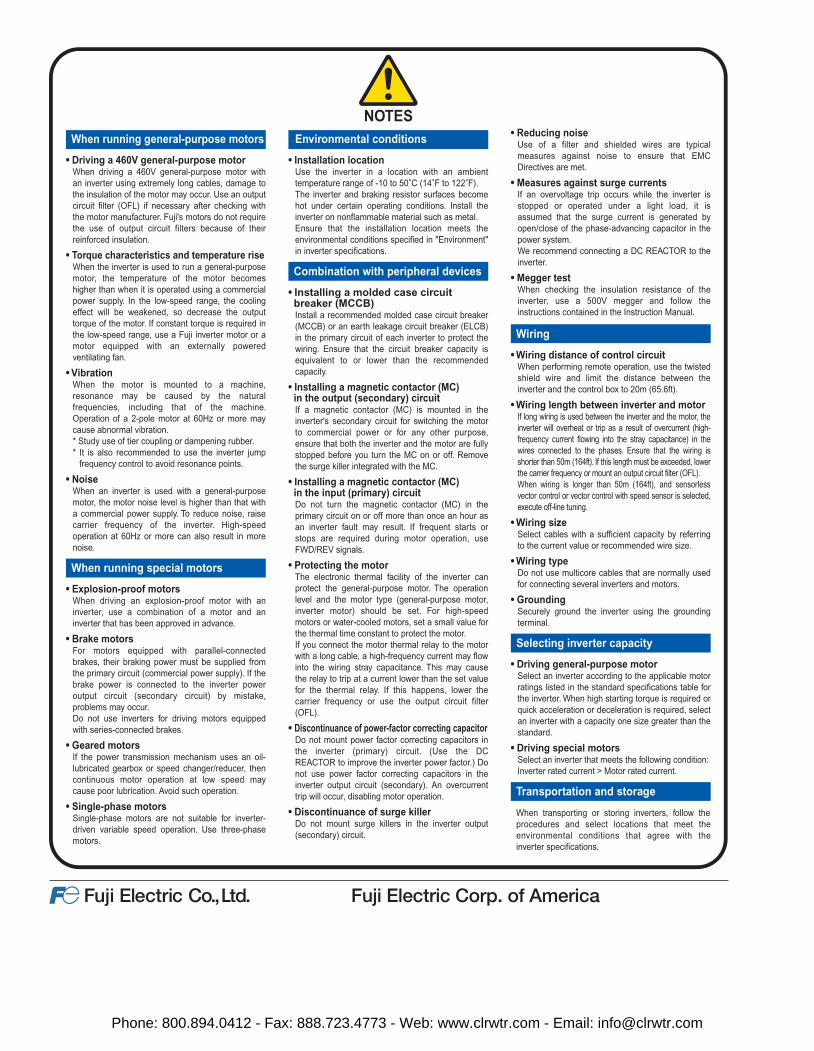
NOTESWhen running general-purpose motors
• Driving a 460V general-purpose motorWhen driving a 460V general-purpose motor withan inverter using extremely long cables, damage tothe insulation of the motor may occur. Use an output circuit filter (OFL) if necessary after checking withthe motor manufacturer. Fuji's motors do not require the use of output circuit filters because of theirreinforced insulation.
• Torque characteristics and temperature riseWhen the inverter is used to run a general-purposemotor, the temperature of the motor becomeshigher than when it is operated using a commercialpower supply. In the low-speed range, the coolingeffect will be weakened, so decrease the outputtorque of the motor. If constant torque is required inthe low-speed range, use a Fuji inverter motor or amotor equipped with an externally poweredventilating fan.
• VibrationWhen the motor is mounted to a machine,resonance may be caused by the naturalfrequencies, including that of the machine.Operation of a 2-pole motor at 60Hz or more maycause abnormal vibration.* Study use of tier coupling or dampening rubber.* It is also recommended to use the inverter jump
frequency control to avoid resonance points.
• NoiseWhen an inverter is used with a general-purposemotor, the motor noise level is higher than that witha commercial power supply. To reduce noise, raisecarrier frequency of the inverter. High-speedoperation at 60Hz or more can also result in morenoise.
When running special motors
• Explosion-proof motorsWhen driving an explosion-proof motor with aninverter, use a combination of a motor and aninverter that has been approved in advance.
• Brake motorsFor motors equipped with parallel-connectedbrakes, their braking power must be supplied fromthe primary circuit (commercial power supply). If the brake power is connected to the inverter poweroutput circuit (secondary circuit) by mistake,problems may occur.Do not use inverters for driving motors equippedwith series-connected brakes.
• Geared motorsIf the power transmission mechanism uses an oil-lubricated gearbox or speed changer/reducer, thencontinuous motor operation at low speed maycause poor lubrication. Avoid such operation.
• Single-phase motorsSingle-phase motors are not suitable for inverter-driven variable speed operation. Use three-phasemotors.
Environmental conditions
• Installation locationUse the inverter in a location with an ambienttemperature range of -10 to 50˚C (14˚F to 122˚F).The inverter and braking resistor surfaces becomehot under certain operating conditions. Install theinverter on nonflammable material such as metal.Ensure that the installation location meets theenvironmental conditions specified in "Environment" in inverter specifications.
Combination with peripheral devices
• Installing a molded case circuitbreaker (MCCB)Install a recommended molded case circuit breaker(MCCB) or an earth leakage circuit breaker (ELCB)in the primary circuit of each inverter to protect thewiring. Ensure that the circuit breaker capacity isequivalent to or lower than the recommendedcapacity.
• Installing a magnetic contactor (MC)in the output (secondary) circuitIf a magnetic contactor (MC) is mounted in theinverter's secondary circuit for switching the motorto commercial power or for any other purpose,ensure that both the inverter and the motor are fully stopped before you turn the MC on or off. Removethe surge killer integrated with the MC.
• Installing a magnetic contactor (MC)in the input (primary) circuitDo not turn the magnetic contactor (MC) in theprimary circuit on or off more than once an hour asan inverter fault may result. If frequent starts orstops are required during motor operation, useFWD/REV signals.
• Protecting the motorThe electronic thermal facility of the inverter canprotect the general-purpose motor. The operationlevel and the motor type (general-purpose motor,inverter motor) should be set. For high-speedmotors or water-cooled motors, set a small value for the thermal time constant to protect the motor.If you connect the motor thermal relay to the motorwith a long cable, a high-frequency current may flow into the wiring stray capacitance. This may causethe relay to trip at a current lower than the set value for the thermal relay. If this happens, lower thecarrier frequency or use the output circuit filter(OFL).
• Discontinuance of power-factor correcting capacitorDo not mount power factor correcting capacitors inthe inverter (primary) circuit. (Use the DCREACTOR to improve the inverter power factor.) Do not use power factor correcting capacitors in theinverter output circuit (secondary). An overcurrenttrip will occur, disabling motor operation.
• Discontinuance of surge killerDo not mount surge killers in the inverter output(secondary) circuit.
• Reducing noiseUse of a filter and shielded wires are typicalmeasures against noise to ensure that EMCDirectives are met.
• Measures against surge currentsIf an overvoltage trip occurs while the inverter isstopped or operated under a light load, it isassumed that the surge current is generated byopen/close of the phase-advancing capacitor in thepower system.We recommend connecting a DC REACTOR to theinverter.
• Megger testWhen checking the insulation resistance of theinverter, use a 500V megger and follow theinstructions contained in the Instruction Manual.
Wiring
• Wiring distance of control circuitWhen performing remote operation, use the twistedshield wire and limit the distance between theinverter and the control box to 20m (65.6ft).
• Wiring length between inverter and motorIf long wiring is used between the inverter and the motor, the inverter will overheat or trip as a result of overcurrent (high-frequency current flowing into the stray capacitance) in thewires connected to the phases. Ensure that the wiring isshorter than 50m (164ft). If this length must be exceeded, lower the carrier frequency or mount an output circuit filter (OFL).When wiring is longer than 50m (164ft), and sensorlessvector control or vector control with speed sensor is selected, execute off-line tuning.
• Wiring sizeSelect cables with a sufficient capacity by referringto the current value or recommended wire size.
• Wiring typeDo not use multicore cables that are normally usedfor connecting several inverters and motors.
• GroundingSecurely ground the inverter using the groundingterminal.
Selecting inverter capacity
• Driving general-purpose motorSelect an inverter according to the applicable motorratings listed in the standard specifications table forthe inverter. When high starting torque is required or quick acceleration or deceleration is required, select an inverter with a capacity one size greater than the standard.
• Driving special motorsSelect an inverter that meets the following condition:Inverter rated current > Motor rated current.
Transportation and storage
When transporting or storing inverters, follow the procedures and select locations that meet the environmental conditions that agree with the inverter specifications.
Phone: 800.894.0412 - Fax: 888.723.4773 - Web: www.clrwtr.com - Email: [email protected]