Embed Size (px)
Citation preview
1
Page 1 Workshop on Astrodynamics Tools and Techniques
ASTRIUM
Low Thrust Missions Guidance & Navigation: the Smart 1 OBAN
experiment results & perspectivesWorkshop on Astrodynamics Tools and Techniques
Page 2 Workshop on Astrodynamics Tools and Techniques
ASTRIUMObNAV Overview
• Camera Sizing (for planet and asteroidencounters)
• Image Processing Modes• Navigation• Guidance• Validation using real images
– Asteroids (Pid du Midi)– Extended Objects (SMART1)
2
Page 3 Workshop on Astrodynamics Tools and Techniques
ASTRIUMObNav Camera
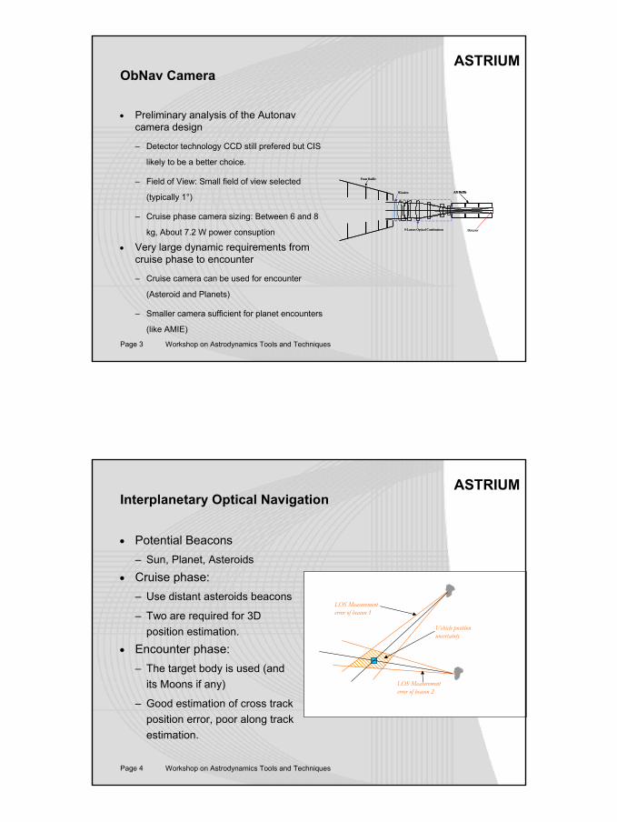
• Preliminary analysis of the Autonavcamera design
– Detector technology CCD still prefered but CIS
likely to be a better choice.
– Field of View: Small field of view selected
(typically 1°)
– Cruise phase camera sizing: Between 6 and 8
kg, About 7.2 W power consuption
• Very large dynamic requirements fromcruise phase to encounter
– Cruise camera can be used for encounter
(Asteroid and Planets)
– Smaller camera sufficient for planet encounters
(like AMIE)
Window
Front Baffle
Aft Baffle
Detector8-Lenses Optical Combination
Window
Front Baffle
Aft BaffleAft Baffle
Detector8-Lenses Optical Combination
Page 4 Workshop on Astrodynamics Tools and Techniques
ASTRIUMInterplanetary Optical Navigation
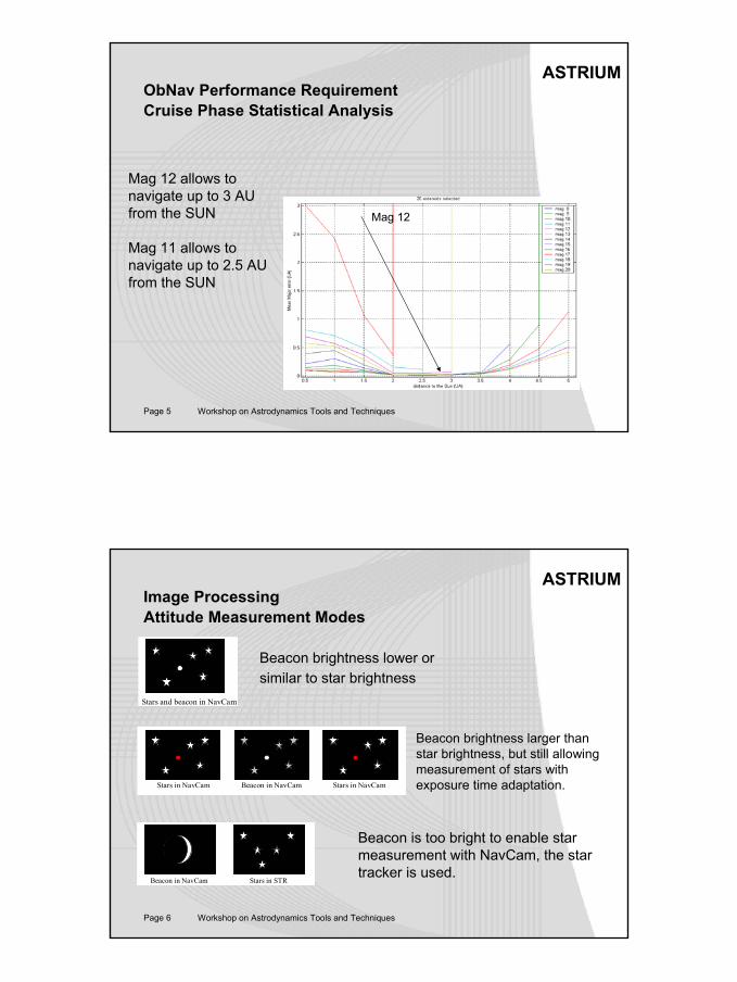
• Potential Beacons– Sun, Planet, Asteroids
• Cruise phase:– Use distant asteroids beacons
– Two are required for 3D position estimation.
• Encounter phase:– The target body is used (and
its Moons if any)
– Good estimation of cross trackposition error, poor along trackestimation.
Vehicle position uncertainty
LOS Measurement error of beacon 1
LOS Measurement error of beacon 2
3
Page 5 Workshop on Astrodynamics Tools and Techniques
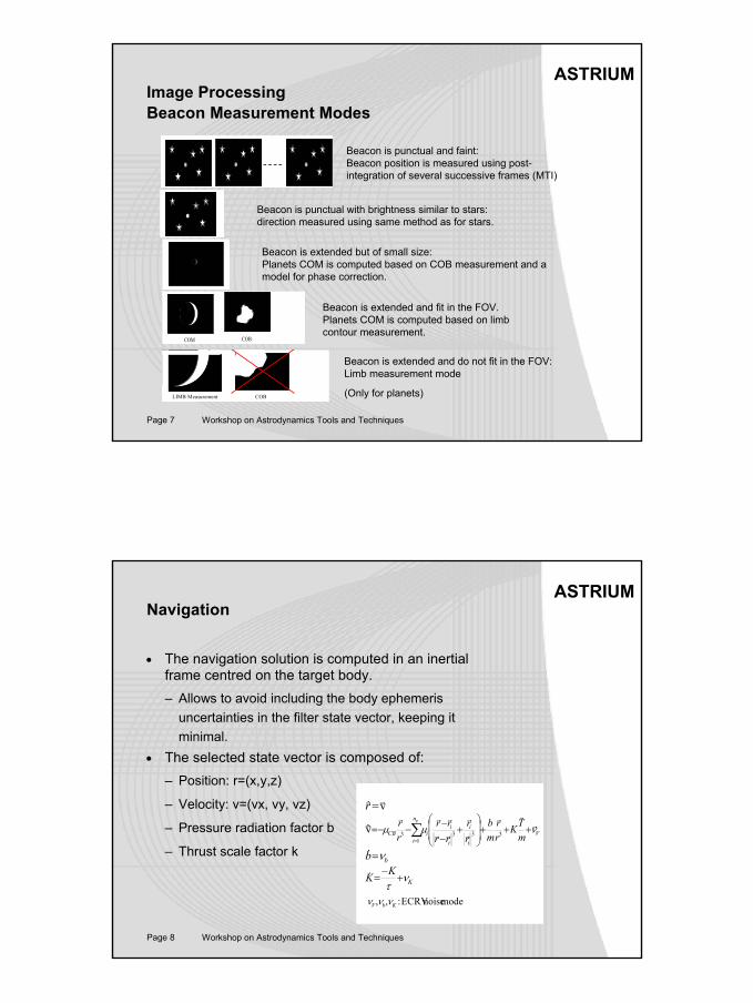
ASTRIUMObNav Performance RequirementCruise Phase Statistical Analysis
Mag 12
Mag 12 allows to navigate up to 3 AU from the SUN
Mag 11 allows to navigate up to 2.5 AU from the SUN
Page 6 Workshop on Astrodynamics Tools and Techniques
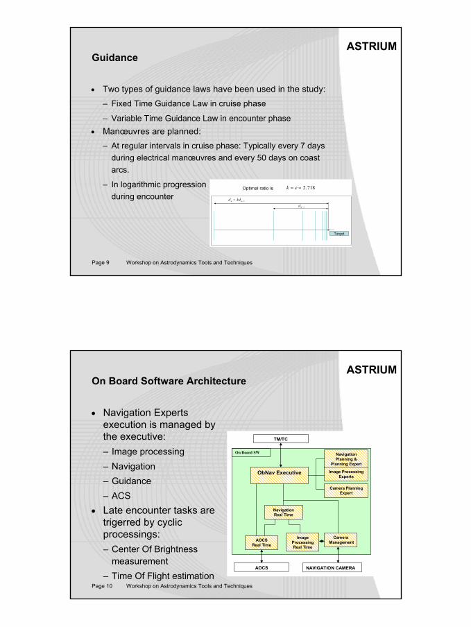
ASTRIUMImage ProcessingAttitude Measurement Modes
Stars and beacon in NavCam
Beacon in NavCamStars in NavCam Stars in NavCam
Stars in STRBeacon in NavCam
Beacon brightness lower or similar to star brightness
Beacon brightness larger than star brightness, but still allowing measurement of stars with exposure time adaptation.
Beacon is too bright to enable star measurement with NavCam, the star tracker is used.
4
Page 7 Workshop on Astrodynamics Tools and Techniques
ASTRIUMImage ProcessingBeacon Measurement Modes
COM COB
LIMB Measurement COB
Beacon is punctual and faint:Beacon position is measured using post-integration of several successive frames (MTI)
Beacon is punctual with brightness similar to stars: direction measured using same method as for stars.
Beacon is extended but of small size: Planets COM is computed based on COB measurement and a model for phase correction.
Beacon is extended and fit in the FOV.Planets COM is computed based on limb contour measurement.
Beacon is extended and do not fit in the FOV:Limb measurement mode
(Only for planets)
Page 8 Workshop on Astrodynamics Tools and Techniques
ASTRIUMNavigation
• The navigation solution is computed in an inertial frame centred on the target body. – Allows to avoid including the body ephemeris
uncertainties in the filter state vector, keeping it minimal.
• The selected state vector is composed of:– Position: r=(x,y,z)
– Velocity: v=(vx, vy, vz)
– Pressure radiation factor b
– Thrust scale factor k
vr&r=r
KKK ντ+
−=&
V
n
i i
i
i
iiCB m
TKrr
mb
rr
rrrr
rr p
νµµ rrr
r
r
rr
rrr&r +++
+
−−
−−= ∑=
31
333v
bb ν=&
modelnoiseECRV:,, KbV ννν
5
Page 9 Workshop on Astrodynamics Tools and Techniques
ASTRIUMGuidance
• Two types of guidance laws have been used in the study:– Fixed Time Guidance Law in cruise phase
– Variable Time Guidance Law in encounter phase• Manœuvres are planned:
– At regular intervals in cruise phase: Typically every 7 daysduring electrical manœuvres and every 50 days on coastarcs.
– In logarithmic progressionduring encounter
1−= nn kdd
1−nd
Target
718.2== ekOptimal ratio is
Page 10 Workshop on Astrodynamics Tools and Techniques
ASTRIUMOn Board Software Architecture
• Navigation Experts execution is managed by the executive:– Image processing– Navigation– Guidance– ACS
• Late encounter tasks are trigerred by cyclicprocessings:– Center Of Brightness
measurement– Time Of Flight estimation
On Board SW
NavigationReal Time
ObNav Executive
Navigation Planning &
Planning Expert
ImageProcessingReal Time
Image ProcessingExperts
AOCSReal Time
Camera PlanningExpert
CameraManagement
NAVIGATION CAMERAAOCS
TM/TC
6
Page 11 Workshop on Astrodynamics Tools and Techniques
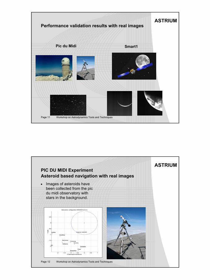
ASTRIUMPerformance validation results with real images
Pic du Midi Smart1
Page 12 Workshop on Astrodynamics Tools and Techniques
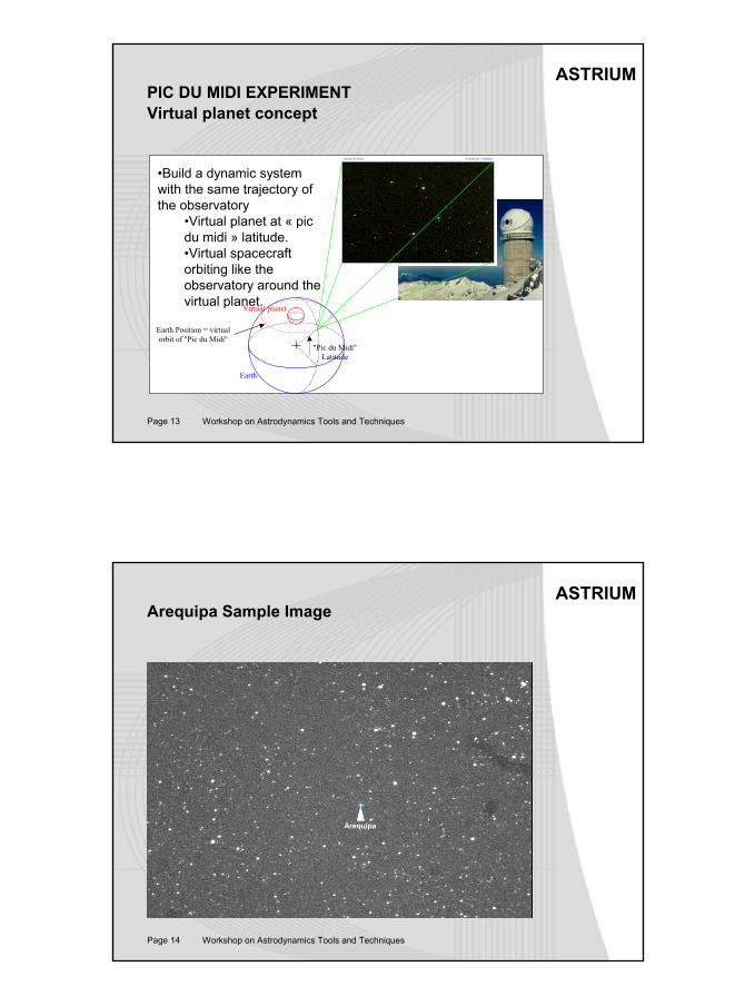
ASTRIUMPIC DU MIDI ExperimentAsteroid based navigation with real images• Images of asteroids have
been collected from the pic du midi observatory withstars in the background.
7
Page 13 Workshop on Astrodynamics Tools and Techniques
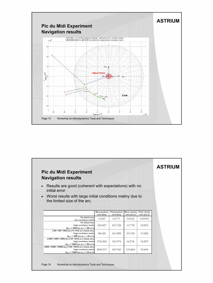
ASTRIUMPIC DU MIDI EXPERIMENTVirtual planet concept
Virtual planet
Earth
"Pic du Midi" Latitude
Earth Position = virtual orbit of "Pic du Midi"
•Build a dynamic systemwith the same trajectory ofthe observatory
•Virtual planet at « pic du midi » latitude.•Virtual spacecraftorbiting like theobservatory around thevirtual planet.
Page 14 Workshop on Astrodynamics Tools and Techniques
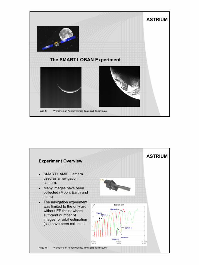
ASTRIUMArequipa Sample Image
Arequipa
8
Page 15 Workshop on Astrodynamics Tools and Techniques
ASTRIUMPic du Midi ExperimentNavigation results
Page 16 Workshop on Astrodynamics Tools and Techniques
ASTRIUMPic du Midi ExperimentNavigation results• Results are good (coherent with expectations) with no
initial error• Worst results with large initial conditions mailny due to
the limited size of the arc.
Mean position error (km)
Final position error (km)
Mean velocity error (m/s)
Final velocity error (m/s)
No initial error,zero covariance matrix 0.1609 0.31771 0.02121 0.029435
No initial error,large covariance matrix
(σpos = 2000 km, σvel = 100 m/s)369.0427 453.7128 15.7738 34.8932
[-500 +500 +500] km [+8 +8 0] m/s initial error,large covariance matrix
(σpos = 2000 km, σvel = 20 m/s)485.424 163.3984 23.1338 11.6822
[-6000 +6000+ 6000] km [+60 +60 0] m/s initial error,large covariance matrix
(σpos = 10000 km, σvel = 100 m/s)1702.3863 345.1974 64.2736 18.2879
[-10000 +10000 +10000] km [+100 +100 0] m/s initial error,large covariance matrix
(σpos = 15000 km, σvel = 150 m/s)2838.9317 424.7043 110.2864 39.6694
9
Page 17 Workshop on Astrodynamics Tools and Techniques
ASTRIUM
The SMART1 OBAN Experiment
Page 18 Workshop on Astrodynamics Tools and Techniques
ASTRIUMExperiment Overview
• SMART1 AMIE Camera used as a navigation camera.
• Many images have beencollected (Moon, Earth andstars)
• The navigation experimentwas limited to the only arc without EP thrust wheresufficient number ofimages for orbit estimation (six) have been collected.
OBAN7-8OBAN11-12
OBAN25-32
OBAN41-48
OBAN49-55
OBAN17-24
10
Page 19 Workshop on Astrodynamics Tools and Techniques
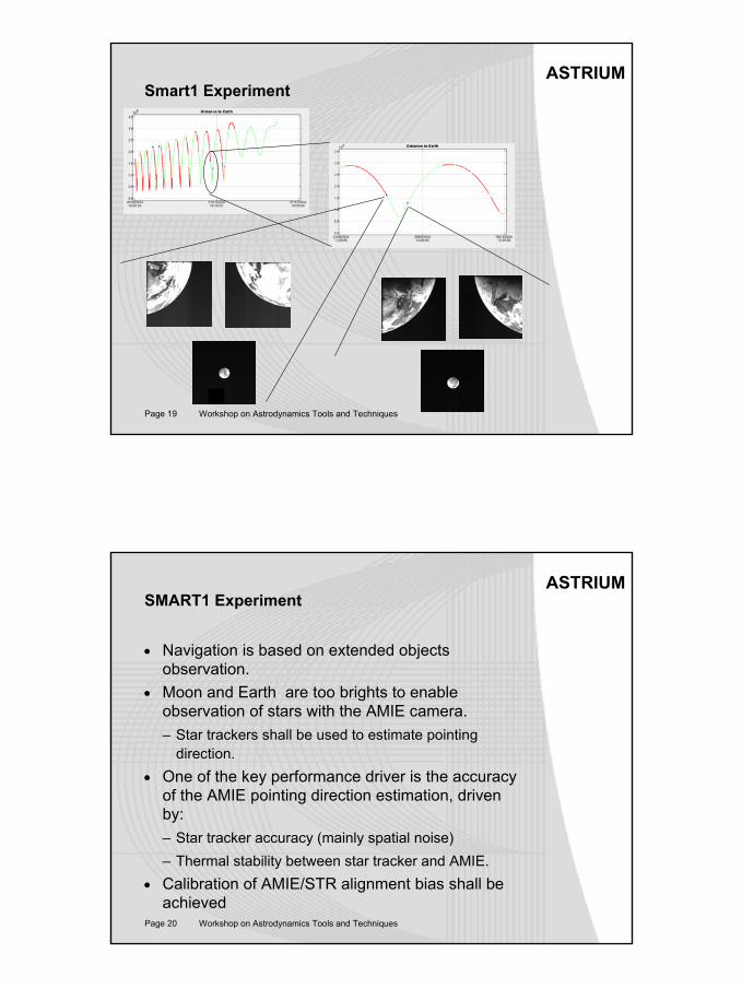
ASTRIUMSmart1 Experiment
Page 20 Workshop on Astrodynamics Tools and Techniques
ASTRIUMSMART1 Experiment
• Navigation is based on extended objectsobservation.
• Moon and Earth are too brights to enableobservation of stars with the AMIE camera.– Star trackers shall be used to estimate pointing
direction.• One of the key performance driver is the accuracy
of the AMIE pointing direction estimation, drivenby:– Star tracker accuracy (mainly spatial noise)– Thermal stability between star tracker and AMIE.
• Calibration of AMIE/STR alignment bias shall beachieved
11
Page 21 Workshop on Astrodynamics Tools and Techniques
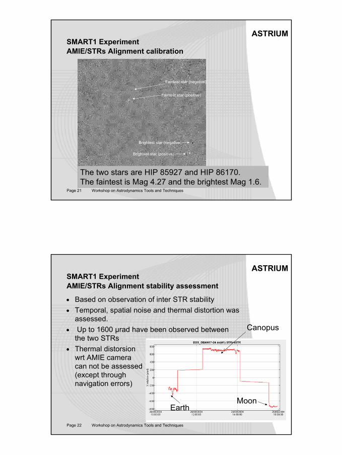
ASTRIUMSMART1 ExperimentAMIE/STRs Alignment calibration
Faintest star (positive)
Faintest star (negative)
Brightest star (positive)
Brightest star (negative)
The two stars are HIP 85927 and HIP 86170. The faintest is Mag 4.27 and the brightest Mag 1.6.
Page 22 Workshop on Astrodynamics Tools and Techniques
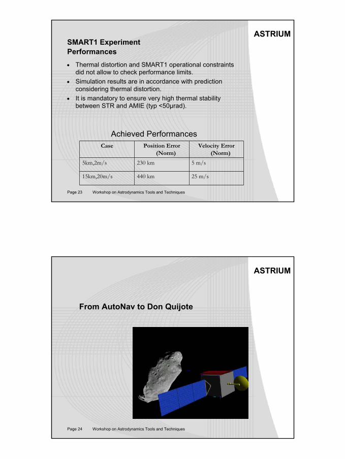
ASTRIUMSMART1 ExperimentAMIE/STRs Alignment stability assessment
• Based on observation of inter STR stability• Temporal, spatial noise and thermal distortion was
assessed.• Up to 1600 µrad have been observed between
the two STRs• Thermal distorsion
wrt AMIE cameracan not be assessed(except throughnavigation errors)
Canopus
EarthMoon
12
Page 23 Workshop on Astrodynamics Tools and Techniques
ASTRIUMSMART1 ExperimentPerformances• Thermal distortion and SMART1 operational constraints
did not allow to check performance limits.• Simulation results are in accordance with prediction
considering thermal distortion.• It is mandatory to ensure very high thermal stability
between STR and AMIE (typ <50µrad).
25 m/s440 km15km,20m/s
5 m/s230 km5km,2m/s
Velocity Error (Norm)
Position Error (Norm)
Case
Achieved Performances
Page 24 Workshop on Astrodynamics Tools and Techniques
ASTRIUM
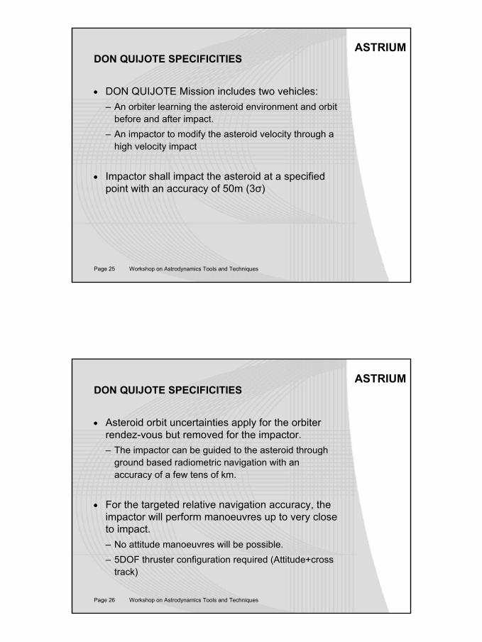
From AutoNav to Don Quijote
13
Page 25 Workshop on Astrodynamics Tools and Techniques
ASTRIUMDON QUIJOTE SPECIFICITIES
• DON QUIJOTE Mission includes two vehicles:– An orbiter learning the asteroid environment and orbit
before and after impact.– An impactor to modify the asteroid velocity through a
high velocity impact
• Impactor shall impact the asteroid at a specifiedpoint with an accuracy of 50m (3σ)
Page 26 Workshop on Astrodynamics Tools and Techniques
ASTRIUMDON QUIJOTE SPECIFICITIES
• Asteroid orbit uncertainties apply for the orbiterrendez-vous but removed for the impactor.– The impactor can be guided to the asteroid through
ground based radiometric navigation with an accuracy of a few tens of km.
• For the targeted relative navigation accuracy, the impactor will perform manoeuvres up to very close to impact.– No attitude manoeuvres will be possible. – 5DOF thruster configuration required (Attitude+cross
track)
14
Page 27 Workshop on Astrodynamics Tools and Techniques
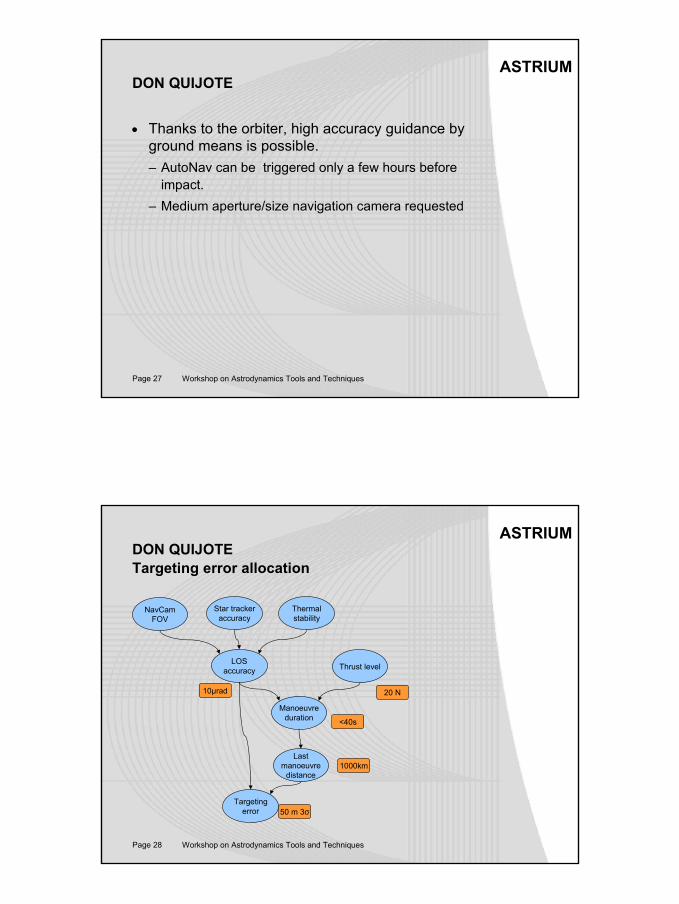
ASTRIUMDON QUIJOTE
• Thanks to the orbiter, high accuracy guidance by ground means is possible.– AutoNav can be triggered only a few hours before
impact.– Medium aperture/size navigation camera requested
Page 28 Workshop on Astrodynamics Tools and Techniques
ASTRIUMDON QUIJOTETargeting error allocation
NavCamFOV
Star trackeraccuracy
LOSaccuracy
Thermalstability
Thrust level
Manoeuvreduration
Lastmanoeuvre
distance
Targetingerror
1000km
50 m 3σ
20 N10µrad
<40s
15
Page 29 Workshop on Astrodynamics Tools and Techniques
ASTRIUMDON QUIJOTE
• Although challenging, requested performances (50m 3σ) is compatible with state of the art S/C and avionics.– Small thrust level– State of the art star tracker– Medium size navigation camera– Low processing load.
• As for SMART experiment, thermal stability is likely to be the most critical but:– Apply on a few thousand seconds instead of days.– Apply for stable pointing.
Page 30 Workshop on Astrodynamics Tools and Techniques
ASTRIUMConclusion
• AutoNav navigation and guidance concept is fully applicable to DON QUIJOTE.
• Lesson learns on SMART1 allows to identify critical contributors.
• 5DOF thrusting capability allows to perform manoeuvres closer (100s before impact instead of 3 hours) and is the main reason for performance improvement.
• The requested 50m can be achieved with state of art sensors but are at the limit of what can be achieved with a conventional S/C.
16
Page 31 Workshop on Astrodynamics Tools and Techniques
ASTRIUMAutonomous Navigation
• AutoNav developed the key technology allowing to perform autonomous navigation and guidance.
– Allowing to achieve level of performances not possible with ground based navigation techniques.
– Providing autonomy in low thrust cruise phases reducing the ground segment load by routine operation.