Embed Size (px)
Citation preview
201 (2006) 4447–4452www.elsevier.com/locate/surfcoat
Surface & Coatings Technology
Low thermal conductivity thermal barrier coating deposited bythe solution plasma spray process
Xinqing Ma a,⁎, Fang Wu b, Jeff Roth a, Maurice Gell b, Eric H. Jordan b
a Inframat Corporation, 74 Batterson Park Road, Farmington, CT 06032, USAb University of Connecticut, 191 Auditorium Rd. Storrs, CT 06269-3139, USA
Available online 25 September 2006
Abstract
This work seeks to develop an innovative thermal barrier coating (TBC) that will exhibit low thermal conductivity and high durabilitycompared with that of current TBCs. To achieve this objective, a multiple component co-doped zirconia chemistry was selected for the topcoat ofthe TBC system, and a new process – Solution Plasma Spray (SPS or SPPS) – was employed to produce desirable microstructural features: the co-doped zirconia TBC contains ultrafine splats, high volume porosity and vertical cracks, for lower thermal conductivity and better durability,respectively. Test results verified a low thermal conductivity of 0.55–0.66 W/K·m over a temperature range of R.T. to 1300 °C, 1/3X that of EB-PVD 8YSZ TBCs, and its thermal cycling durability was 2.5X that of APS 8YSZ TBCs and 1.5X that of EB-PVD 8YSZ TBCs.© 2006 Elsevier B.V. All rights reserved.
Keywords: Thermal barrier coating; Low thermal conductivity; Solution precursor plasma spray process; Thermal cycle test; High temperature
1. Introduction
Thermal barrier coatings (TBCs) are widely used to insulatemetallic components in gas-turbine engines from high tem-peratures, and have become the critical material for turbinedurability and efficiency, performance as well as overhaul andrepair frequency in gas turbine engines [1,2]. In particular,aeroengine hot-section protection is an acute need due to theconstant increases in turbine inlet temperatures. In militaryaircraft turbines, the gas temperature rises to N1600 °C and toN1500 °C for commercial aircraft. TBCs remain the mosteffective thermal insulation approach, and their developmenthas centered on partially stabilized zirconia (typically, 7-8YSZ).However, state-of-the-art Atmospheric Plasma Spray (APS) orElectron Beam Physical Vapor Deposition (EB-PVD) 7-8YSZTBCs are approaching their durability and temperature limits,which persists as a challenge to overcome in the near future.
In recent years, new classes of ceramic materials having verylow thermal conductivity and better high temperature stabilityhave been identified as potential successors to YSZ. Zirconium
⁎ Corresponding author. Tel.: +1 860 486 2358; fax: +1 860 486 1164.E-mail address: [email protected] (X. Ma).
0257-8972/$ - see front matter © 2006 Elsevier B.V. All rights reserved.doi:10.1016/j.surfcoat.2006.08.095
phosphates have lower thermal conductivity than YSZ and theircoefficients of thermal expansion (“CTEs”) can be tailored byionic substitution of Na, Ca, Sr, Ba, Mg, Cd, and other groups ofIA and IIA atoms into crystal structures [2–6]. Similarly,zirconates with a perovskite structure (SrZrO3, BaZrO3) or afluorite structure (La2Zr2O7, Gd2Zr2O7, Nd2Zr2O7,) [7,8], andyttrium aluminum garnet based ceramics (such as Y3Al5O12,Y3Fe5O12, Y3Al0.7Fe 4.3O12, Y3Al1.4Fe3.6O12) have been tested.Some of these such as La2Zr2O7 (1.6 W/m·K) and Gd2Zr2O7
(1.14 W/m·K) have lower thermal conductivity and better phasestability than YSZ (2.45 W/m·K) at N1200 °C, and thus weredeveloped for low thermal conductivity TBC systems by severalmajor engine manufactures [9–13].
Another group of co-doped zirconia ceramics is quite attrac-tive because of low thermal conductivity and high stability.ZrO2–CeO2–Y2O3 has low thermal conductivity relative toYSZ, but disintegrates, especially under reducing atmosphere attemperatures N1100 °C [14,15]. Zhu and colleagues discoveredrare earth oxide multi-doped ZrO2–Y2O3 for new TBCs[16,17]. The lowest thermal conductivity of the multi-com-ponent ceramic layer was about 0.6 W/m·K, which is 0.5 timesthat of 8YSZ. Outstanding merits of the new TBCs includeenhanced sintering resistance, good phase stability, and im-proved durability.
4448 X. Ma et al. / Surface & Coatings Technology 201 (2006) 4447–4452
2. Experimental procedure
2.1. Solution precursor feedstock
The compositions of the multi-component zirconia-base low-K ceramics were adopted from those developed by Zhu and co-workers [16,17]. The multi-component ceramic is co-doped withrare earth oxides such as yttrium oxide and gadolinium oxide.Solution precursor of the co-doped zirconia by multiple rare earthelements was prepared by dissolving rare earth salts into anaqueous zirconium solution according to their stoichiometricformula. The precursor solution is water-based, which makes itmore stable and less toxic than some organic based precursors.
2.2. Solution plasma spray
The Solution Plasma Spray (SPS) system uses standard plasmatorches and robotics, but the powder feeding system is replaced by asolution precursor storage, feeding and injection system [18–21].The low-K TBC topcoats were deposited using a robot-operatedMetco 9MB plasma torch (Sulzer-Metco, Westbury, NY) fromsolution precursors. The plasma power used was in the range of35–45 kW, and Ar and H2 were used as primary and secondaryplasma gases, respectively. A six-axis robot (GMFanuc, S-700)was used to manipulate the plasma gun movement and spraypattern and area. A liquid delivery and injection system (InframatCorporation, Farmington, CT) was utilized to store, deliver, andinject the liquid precursors. An atomizer was employed to generatefine-size and high velocity liquid droplets, which were subse-quently fed into the plasma plume. Ni-base superalloy disks(mostly, CMSX-4, diameter 25 mm, thickness 3–5 mm), coatedwith bondcoats were used as substrates for the coatings depositedfor microstructural and thermal property evaluation and thermalcycling tests. Two types of bondcoats were applied to the super-alloy substrates. A NiCrAlY-type bondcoat was applied usingatmospheric plasma spray. The bondcoating has a thickness ofabout 120–150 μm. A Pt-modified bondcoat was made byelectroplating of a thin Pt layer on CMSX-4 substrate and conse-quentially treated in a thermal interdiffusion process.
2.3. Thermal conductivity tests
Thermal conductivity of the low-K zirconia TBCs wasmeasured by two test methods: laser flash method and laser highheat-fluxmethod. In laser flashmethod, specific heatwasmeasuredusing differential scanning calorimeters. The thermal conductivitywas calculated as a product of these quantities. Test sample sizes are12.7×12.7×3.8 mm3 and coating thickness 250–300 μm. Thesamples consist of a SPS-formed topcoat APS-formed NiCrAlYbondcoat and a CMSX-4 substrate. The SPS TBCs were measuredat a temperature range of R.T to 1300 °C in air. The accuracy of thethermal diffusivity measurements is ±5%. The laser high heat-fluxmethod and test rig was originally developed by the NASA-GlennResearch Center (GRC) [22,23]. Thermal conductivities of thesecoatings were tested in “real-time”while the samples were exposedto a high heat-flux laser cycling test. Test sample sizes are 25mm india.×3 mm thick and coating thickness 250–300 μm. The surface
temperature is 1350 °C, coat-substrate interface 1121 °C andsubstrate 1010 °C. Thermal conductivity was determined based onthe applied laser heat-flux and the measured temperature gradientacross the coating.
2.4. Thermal cycling tests
Thermal cycling tests of the low-K zirconia TBCs wereconducted under two different conditions: Thermal cycling testswere run in a furnace and using a laser generated high-heat fluxrig. One cycle in the furnace test (CM rapid heating furnace,Bloomfield, NJ) consisted of a 50-min heat up, a 45minute hold atthe maximum temperature and 10minutes of forced air cooling tonear ambient temperature. There was no significant thermalgradient across the coating thickness during the heating period.The tested samples were vertically positioned in a sample holderthat could move up/down together with an elevator attached. Anair fan was used to force cooling the samples. Coating lifetime tofailure is defined as the hours or cycles at which the spalled ordelaminated area is over 50% of total coating surface.
The laser high heat-flux thermal cycling test was performedsimultaneously with the thermal conductivity test mentionedabove. One cycle consists of a 30-min heating at a surfacetemperature 1350 °C and a 3-min cooling. A 3.0 KW CO2 laser(wavelength 10.6 μm) high heat-flux rig was established toconduct the test at NASA-GRC. There was a temperature gradient(∼230 °C in this case) across the ceramic coating during the laserexposure. The samples of SPS-TBCs were pre-oxidized isother-mally at 1121 °C for 400 h in air. Then, the oxidized TBC sampleswere used for the high heat-flux cycling test.
2.5. Characterization and evaluation
Themicrostructures of the SPSTBCswere characterized usingan optical microscope (Macrophot, Nikon, Japan) and a scanningelectron microscope (JSM6335F, JEOL, Japan) equipped with afield emission source. The microstructural features characterizedinclude coating thickness and its evenness, cracks (space andlength), splats, interface, pore size and distribution. The overallcoating porosity/density was measured according to ASTMStandard C693-84 (Archimedean porosimetry) and porositydistribution was determined by mercury intrusion method.
Phase structures of the SPS TBCs were analyzed using X-raydiffraction method. X-ray diffraction (XRD) analysis (Cu Kαradiation; D5005, Bruker AXS, Madison, WI) was carried out todetermine the phase structure of the SPS-formed low-K ceramics.The TGOs formed on the oxidized bondcoats and the tested TBCsalso were assessed with the same method. In addition, coatingmicrohardness was measured on the cross-sections of the SPSTBCs using a digital hardness tester (Vickers indenter, 300 g load).
3. Experimental results and discussion
3.1. Strain-tolerant microstructures
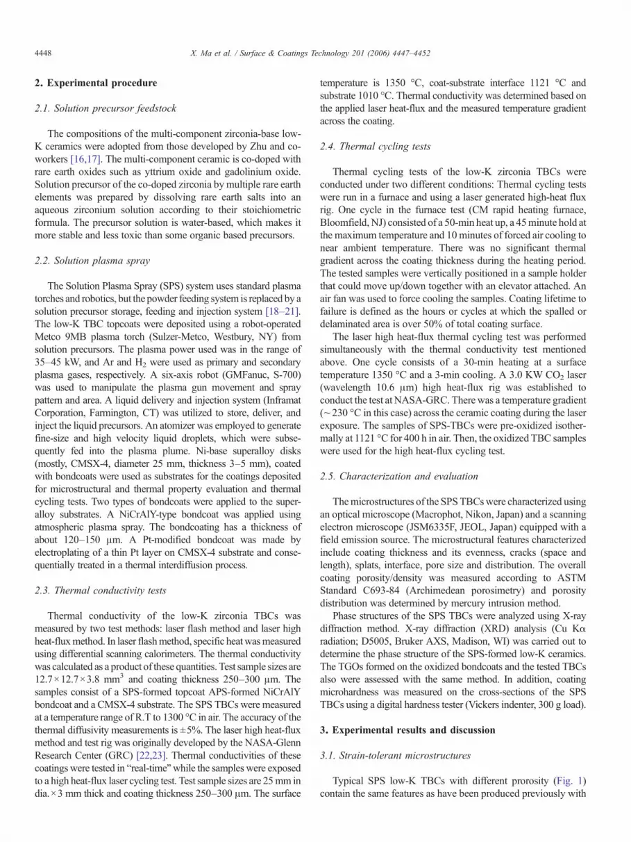
Typical SPS low-K TBCs with different prorosity (Fig. 1)contain the same features as have been produced previously with
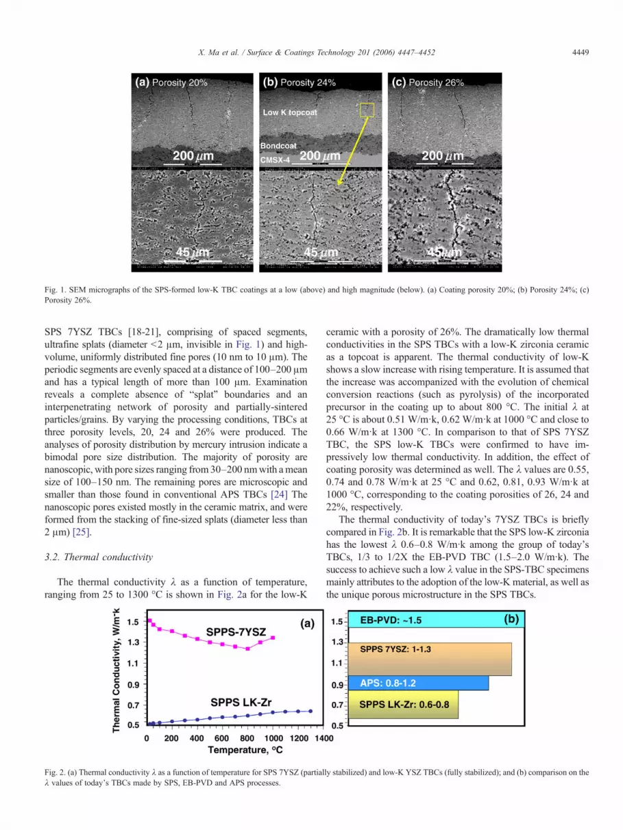
Fig. 1. SEM micrographs of the SPS-formed low-K TBC coatings at a low (above) and high magnitude (below). (a) Coating porosity 20%; (b) Porosity 24%; (c)Porosity 26%.
4449X. Ma et al. / Surface & Coatings Technology 201 (2006) 4447–4452
SPS 7YSZ TBCs [18-21], comprising of spaced segments,ultrafine splats (diameter b2 μm, invisible in Fig. 1) and high-volume, uniformly distributed fine pores (10 nm to 10 μm). Theperiodic segments are evenly spaced at a distance of 100–200 μmand has a typical length of more than 100 μm. Examinationreveals a complete absence of “splat” boundaries and aninterpenetrating network of porosity and partially-sinteredparticles/grains. By varying the processing conditions, TBCs atthree porosity levels, 20, 24 and 26% were produced. Theanalyses of porosity distribution by mercury intrusion indicate abimodal pore size distribution. The majority of porosity arenanoscopic, with pore sizes ranging from30–200 nmwith ameansize of 100–150 nm. The remaining pores are microscopic andsmaller than those found in conventional APS TBCs [24] Thenanoscopic pores existed mostly in the ceramic matrix, and wereformed from the stacking of fine-sized splats (diameter less than2 μm) [25].
3.2. Thermal conductivity
The thermal conductivity λ as a function of temperature,ranging from 25 to 1300 °C is shown in Fig. 2a for the low-K
Fig. 2. (a) Thermal conductivity λ as a function of temperature for SPS 7YSZ (partialλ values of today's TBCs made by SPS, EB-PVD and APS processes.
ceramic with a porosity of 26%. The dramatically low thermalconductivities in the SPS TBCs with a low-K zirconia ceramicas a topcoat is apparent. The thermal conductivity of low-Kshows a slow increase with rising temperature. It is assumed thatthe increase was accompanized with the evolution of chemicalconversion reactions (such as pyrolysis) of the incorporatedprecursor in the coating up to about 800 °C. The initial λ at25 °C is about 0.51 W/m·k, 0.62 W/m·k at 1000 °C and close to0.66 W/m·k at 1300 °C. In comparison to that of SPS 7YSZTBC, the SPS low-K TBCs were confirmed to have im-pressively low thermal conductivity. In addition, the effect ofcoating porosity was determined as well. The λ values are 0.55,0.74 and 0.78 W/m·k at 25 °C and 0.62, 0.81, 0.93 W/m·k at1000 °C, corresponding to the coating porosities of 26, 24 and22%, respectively.
The thermal conductivity of today's 7YSZ TBCs is brieflycompared in Fig. 2b. It is remarkable that the SPS low-K zirconiahas the lowest λ 0.6–0.8 W/m·k among the group of today'sTBCs, 1/3 to 1/2X the EB-PVD TBC (1.5–2.0 W/m·k). Thesuccess to achieve such a low λ value in the SPS-TBC specimensmainly attributes to the adoption of the low-K material, as well asthe unique porous microstructure in the SPS TBCs.
ly stabilized) and low-K YSZ TBCs (fully stabilized); and (b) comparison on the
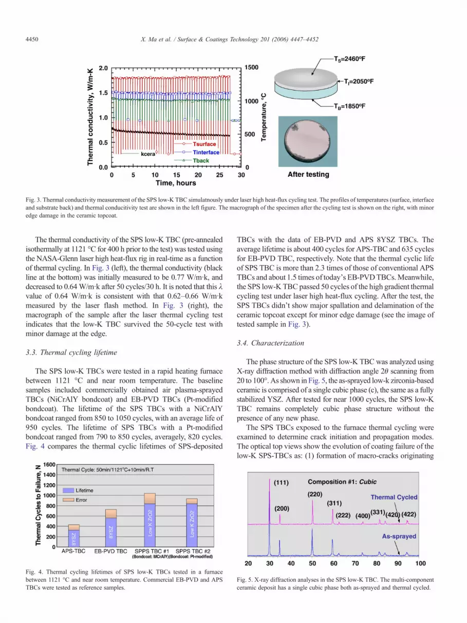
Fig. 3. Thermal conductivity measurement of the SPS low-K TBC simulatnously under laser high heat-flux cycling test. The profiles of temperatures (surface, interfaceand substrate back) and thermal conducitivity test are shown in the left figure. The macrograph of the specimen after the cycling test is shown on the right, with minoredge damage in the ceramic topcoat.
4450 X. Ma et al. / Surface & Coatings Technology 201 (2006) 4447–4452
The thermal conductivity of the SPS low-K TBC (pre-annealedisothermally at 1121 °C for 400 h prior to the test) was tested usingthe NASA-Glenn laser high heat-flux rig in real-time as a functionof thermal cycling. In Fig. 3 (left), the thermal conductivity (blackline at the bottom) was initially measured to be 0.77 W/m·k, anddecreased to 0.64W/m·k after 50 cycles/30 h. It is noted that this λvalue of 0.64 W/m·k is consistent with that 0.62–0.66 W/m·kmeasured by the laser flash method. In Fig. 3 (right), themacrograph of the sample after the laser thermal cycling testindicates that the low-K TBC survived the 50-cycle test withminor damage at the edge.
3.3. Thermal cycling lifetime
The SPS low-K TBCs were tested in a rapid heating furnacebetween 1121 °C and near room temperature. The baselinesamples included commercially obtained air plasma-sprayedTBCs (NiCrAlY bondcoat) and EB-PVD TBCs (Pt-modifiedbondcoat). The lifetime of the SPS TBCs with a NiCrAlYbondcoat ranged from 850 to 1050 cycles, with an average life of950 cycles. The lifetime of SPS TBCs with a Pt-modifiedbondcoat ranged from 790 to 850 cycles, averagely, 820 cycles.Fig. 4 compares the thermal cyclic lifetimes of SPS-deposited
Fig. 4. Thermal cycling lifetimes of SPS low-K TBCs tested in a furnacebetween 1121 °C and near room temperature. Commercial EB-PVD and APSTBCs were tested as reference samples.
TBCs with the data of EB-PVD and APS 8YSZ TBCs. Theaverage lifetime is about 400 cycles for APS-TBC and 635 cyclesfor EB-PVD TBC, respectively. Note that the thermal cyclic lifeof SPS TBC is more than 2.3 times of those of conventional APSTBCs and about 1.5 times of today's EB-PVDTBCs.Meanwhile,the SPS low-K TBC passed 50 cycles of the high gradient thermalcycling test under laser high heat-flux cycling. After the test, theSPS TBCs didn't show major spallation and delamination of theceramic topcoat except for minor edge damage (see the image oftested sample in Fig. 3).
3.4. Characterization
The phase structure of the SPS low-K TBCwas analyzed usingX-ray diffraction method with diffraction angle 2θ scanning from20 to 100°. As shown in Fig. 5, the as-sprayed low-k zirconia-basedceramic is comprised of a single cubic phase (c), the same as a fullystabilized YSZ. After tested for near 1000 cycles, the SPS low-KTBC remains completely cubic phase structure without thepresence of any new phase.
The SPS TBCs exposed to the furnace thermal cycling wereexamined to determine crack initiation and propagation modes.The optical top views show the evolution of coating failure of thelow-K SPS-TBCs as: (1) formation of macro-cracks originating
Fig. 5. X-ray diffraction analyses in the SPS low-K TBC. The multi-componentceramic deposit has a single cubic phase both as-sprayed and thermal cycled.
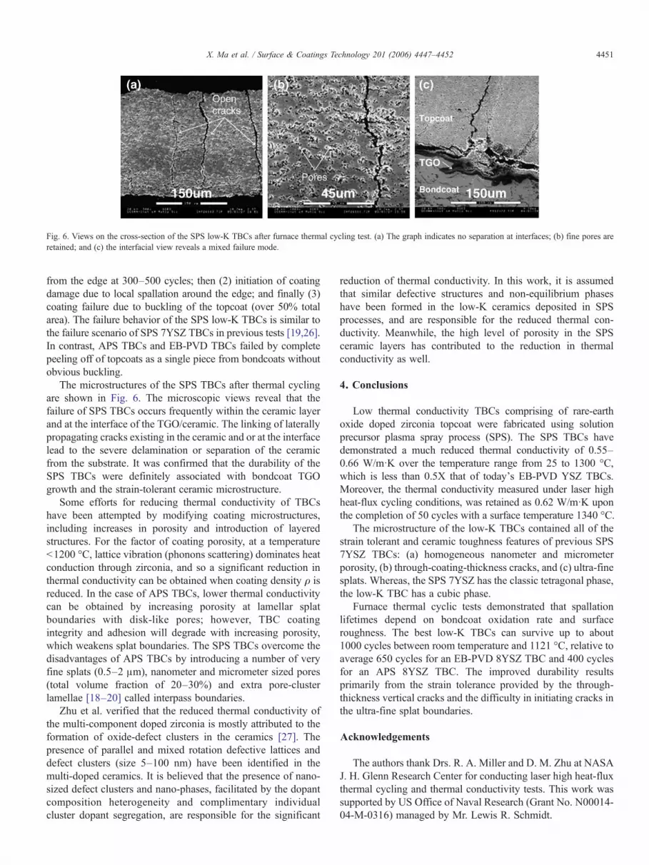
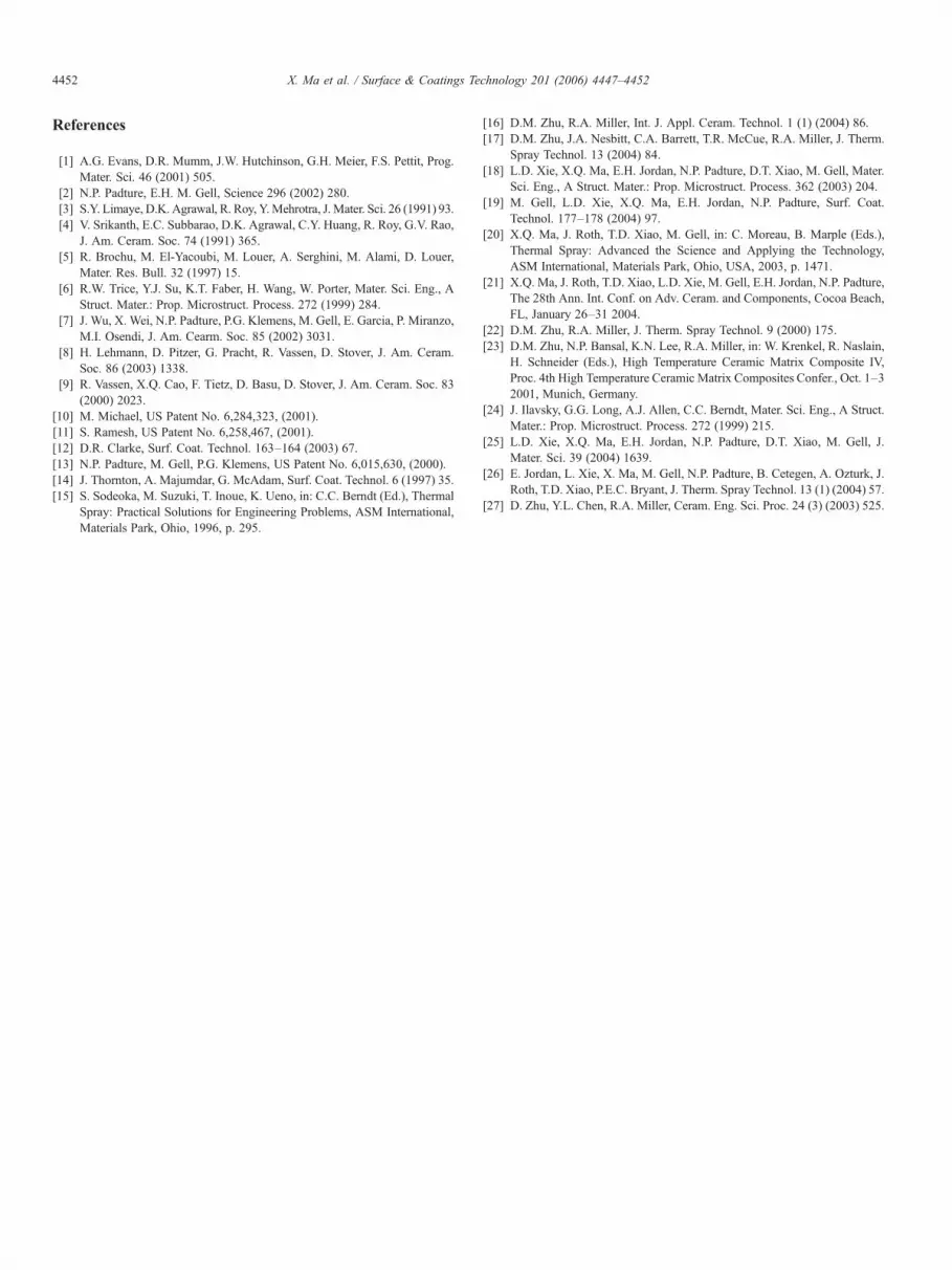
Fig. 6. Views on the cross-section of the SPS low-K TBCs after furnace thermal cycling test. (a) The graph indicates no separation at interfaces; (b) fine pores areretained; and (c) the interfacial view reveals a mixed failure mode.
4451X. Ma et al. / Surface & Coatings Technology 201 (2006) 4447–4452
from the edge at 300–500 cycles; then (2) initiation of coatingdamage due to local spallation around the edge; and finally (3)coating failure due to buckling of the topcoat (over 50% totalarea). The failure behavior of the SPS low-K TBCs is similar tothe failure scenario of SPS 7YSZ TBCs in previous tests [19,26].In contrast, APS TBCs and EB-PVD TBCs failed by completepeeling off of topcoats as a single piece from bondcoats withoutobvious buckling.
The microstructures of the SPS TBCs after thermal cyclingare shown in Fig. 6. The microscopic views reveal that thefailure of SPS TBCs occurs frequently within the ceramic layerand at the interface of the TGO/ceramic. The linking of laterallypropagating cracks existing in the ceramic and or at the interfacelead to the severe delamination or separation of the ceramicfrom the substrate. It was confirmed that the durability of theSPS TBCs were definitely associated with bondcoat TGOgrowth and the strain-tolerant ceramic microstructure.
Some efforts for reducing thermal conductivity of TBCshave been attempted by modifying coating microstructures,including increases in porosity and introduction of layeredstructures. For the factor of coating porosity, at a temperatureb1200 °C, lattice vibration (phonons scattering) dominates heatconduction through zirconia, and so a significant reduction inthermal conductivity can be obtained when coating density ρ isreduced. In the case of APS TBCs, lower thermal conductivitycan be obtained by increasing porosity at lamellar splatboundaries with disk-like pores; however, TBC coatingintegrity and adhesion will degrade with increasing porosity,which weakens splat boundaries. The SPS TBCs overcome thedisadvantages of APS TBCs by introducing a number of veryfine splats (0.5–2 μm), nanometer and micrometer sized pores(total volume fraction of 20–30%) and extra pore-clusterlamellae [18–20] called interpass boundaries.
Zhu et al. verified that the reduced thermal conductivity ofthe multi-component doped zirconia is mostly attributed to theformation of oxide-defect clusters in the ceramics [27]. Thepresence of parallel and mixed rotation defective lattices anddefect clusters (size 5–100 nm) have been identified in themulti-doped ceramics. It is believed that the presence of nano-sized defect clusters and nano-phases, facilitated by the dopantcomposition heterogeneity and complimentary individualcluster dopant segregation, are responsible for the significant
reduction of thermal conductivity. In this work, it is assumedthat similar defective structures and non-equilibrium phaseshave been formed in the low-K ceramics deposited in SPSprocesses, and are responsible for the reduced thermal con-ductivity. Meanwhile, the high level of porosity in the SPSceramic layers has contributed to the reduction in thermalconductivity as well.
4. Conclusions
Low thermal conductivity TBCs comprising of rare-earthoxide doped zirconia topcoat were fabricated using solutionprecursor plasma spray process (SPS). The SPS TBCs havedemonstrated a much reduced thermal conductivity of 0.55–0.66 W/m·K over the temperature range from 25 to 1300 °C,which is less than 0.5X that of today's EB-PVD YSZ TBCs.Moreover, the thermal conductivity measured under laser highheat-flux cycling conditions, was retained as 0.62 W/m·K uponthe completion of 50 cycles with a surface temperature 1340 °C.
The microstructure of the low-K TBCs contained all of thestrain tolerant and ceramic toughness features of previous SPS7YSZ TBCs: (a) homogeneous nanometer and micrometerporosity, (b) through-coating-thickness cracks, and (c) ultra-finesplats. Whereas, the SPS 7YSZ has the classic tetragonal phase,the low-K TBC has a cubic phase.
Furnace thermal cyclic tests demonstrated that spallationlifetimes depend on bondcoat oxidation rate and surfaceroughness. The best low-K TBCs can survive up to about1000 cycles between room temperature and 1121 °C, relative toaverage 650 cycles for an EB-PVD 8YSZ TBC and 400 cyclesfor an APS 8YSZ TBC. The improved durability resultsprimarily from the strain tolerance provided by the through-thickness vertical cracks and the difficulty in initiating cracks inthe ultra-fine splat boundaries.
Acknowledgements
The authors thank Drs. R. A. Miller and D. M. Zhu at NASAJ. H. Glenn Research Center for conducting laser high heat-fluxthermal cycling and thermal conductivity tests. This work wassupported by US Office of Naval Research (Grant No. N00014-04-M-0316) managed by Mr. Lewis R. Schmidt.
4452 X. Ma et al. / Surface & Coatings Technology 201 (2006) 4447–4452
References
[1] A.G. Evans, D.R. Mumm, J.W. Hutchinson, G.H. Meier, F.S. Pettit, Prog.Mater. Sci. 46 (2001) 505.
[2] N.P. Padture, E.H. M. Gell, Science 296 (2002) 280.[3] S.Y. Limaye, D.K. Agrawal, R. Roy, Y.Mehrotra, J.Mater. Sci. 26 (1991) 93.[4] V. Srikanth, E.C. Subbarao, D.K. Agrawal, C.Y. Huang, R. Roy, G.V. Rao,
J. Am. Ceram. Soc. 74 (1991) 365.[5] R. Brochu, M. El-Yacoubi, M. Louer, A. Serghini, M. Alami, D. Louer,
Mater. Res. Bull. 32 (1997) 15.[6] R.W. Trice, Y.J. Su, K.T. Faber, H. Wang, W. Porter, Mater. Sci. Eng., A
Struct. Mater.: Prop. Microstruct. Process. 272 (1999) 284.[7] J. Wu, X. Wei, N.P. Padture, P.G. Klemens, M. Gell, E. Garcia, P. Miranzo,
M.I. Osendi, J. Am. Cearm. Soc. 85 (2002) 3031.[8] H. Lehmann, D. Pitzer, G. Pracht, R. Vassen, D. Stover, J. Am. Ceram.
Soc. 86 (2003) 1338.[9] R. Vassen, X.Q. Cao, F. Tietz, D. Basu, D. Stover, J. Am. Ceram. Soc. 83
(2000) 2023.[10] M. Michael, US Patent No. 6,284,323, (2001).[11] S. Ramesh, US Patent No. 6,258,467, (2001).[12] D.R. Clarke, Surf. Coat. Technol. 163–164 (2003) 67.[13] N.P. Padture, M. Gell, P.G. Klemens, US Patent No. 6,015,630, (2000).[14] J. Thornton, A. Majumdar, G. McAdam, Surf. Coat. Technol. 6 (1997) 35.[15] S. Sodeoka, M. Suzuki, T. Inoue, K. Ueno, in: C.C. Berndt (Ed.), Thermal
Spray: Practical Solutions for Engineering Problems, ASM International,Materials Park, Ohio, 1996, p. 295.
[16] D.M. Zhu, R.A. Miller, Int. J. Appl. Ceram. Technol. 1 (1) (2004) 86.[17] D.M. Zhu, J.A. Nesbitt, C.A. Barrett, T.R. McCue, R.A. Miller, J. Therm.
Spray Technol. 13 (2004) 84.[18] L.D. Xie, X.Q. Ma, E.H. Jordan, N.P. Padture, D.T. Xiao, M. Gell, Mater.
Sci. Eng., A Struct. Mater.: Prop. Microstruct. Process. 362 (2003) 204.[19] M. Gell, L.D. Xie, X.Q. Ma, E.H. Jordan, N.P. Padture, Surf. Coat.
Technol. 177–178 (2004) 97.[20] X.Q. Ma, J. Roth, T.D. Xiao, M. Gell, in: C. Moreau, B. Marple (Eds.),
Thermal Spray: Advanced the Science and Applying the Technology,ASM International, Materials Park, Ohio, USA, 2003, p. 1471.
[21] X.Q. Ma, J. Roth, T.D. Xiao, L.D. Xie, M. Gell, E.H. Jordan, N.P. Padture,The 28th Ann. Int. Conf. on Adv. Ceram. and Components, Cocoa Beach,FL, January 26–31 2004.
[22] D.M. Zhu, R.A. Miller, J. Therm. Spray Technol. 9 (2000) 175.[23] D.M. Zhu, N.P. Bansal, K.N. Lee, R.A. Miller, in: W. Krenkel, R. Naslain,
H. Schneider (Eds.), High Temperature Ceramic Matrix Composite IV,Proc. 4th High Temperature Ceramic Matrix Composites Confer., Oct. 1–32001, Munich, Germany.
[24] J. Ilavsky, G.G. Long, A.J. Allen, C.C. Berndt, Mater. Sci. Eng., A Struct.Mater.: Prop. Microstruct. Process. 272 (1999) 215.
[25] L.D. Xie, X.Q. Ma, E.H. Jordan, N.P. Padture, D.T. Xiao, M. Gell, J.Mater. Sci. 39 (2004) 1639.
[26] E. Jordan, L. Xie, X. Ma, M. Gell, N.P. Padture, B. Cetegen, A. Ozturk, J.Roth, T.D. Xiao, P.E.C. Bryant, J. Therm. Spray Technol. 13 (1) (2004) 57.
[27] D. Zhu, Y.L. Chen, R.A. Miller, Ceram. Eng. Sci. Proc. 24 (3) (2003) 525.