Embed Size (px)
Citation preview
Hubbard 2006
Low Temperature CureLow Temperature Cure
of PBO Films on Wafersof PBO Films on Wafers
Bob Hubbard, Keith Hicks
Lambda Technologies, Inc.
Masayuki Ohe, Tomoko Kawamura
HD MicroSystems
Custom Polymer Design
Hubbard 2006
Designing a LowDesigning a Low--Temp PolymerTemp Polymer
� Increasing interest in low temperatures
� Moving to lower temperature sensitive devices (<200C)
� Need lower thermal budget for wafers & packages
� Need the same film properties (high Tg, elongation, etc.)
� Low stress and tailored mechanical properties
� Recent progress
� 150-200ºC polyimides (10th Symposium on Polymers)
� Lowered stress epoxies and silicones 2005
� Polybenzoxazoles (PBO) wafer films
� Water processed
� Mechanical properties similar to polyimides
Hubbard 2006
Limits to Convection CuringLimits to Convection Curing
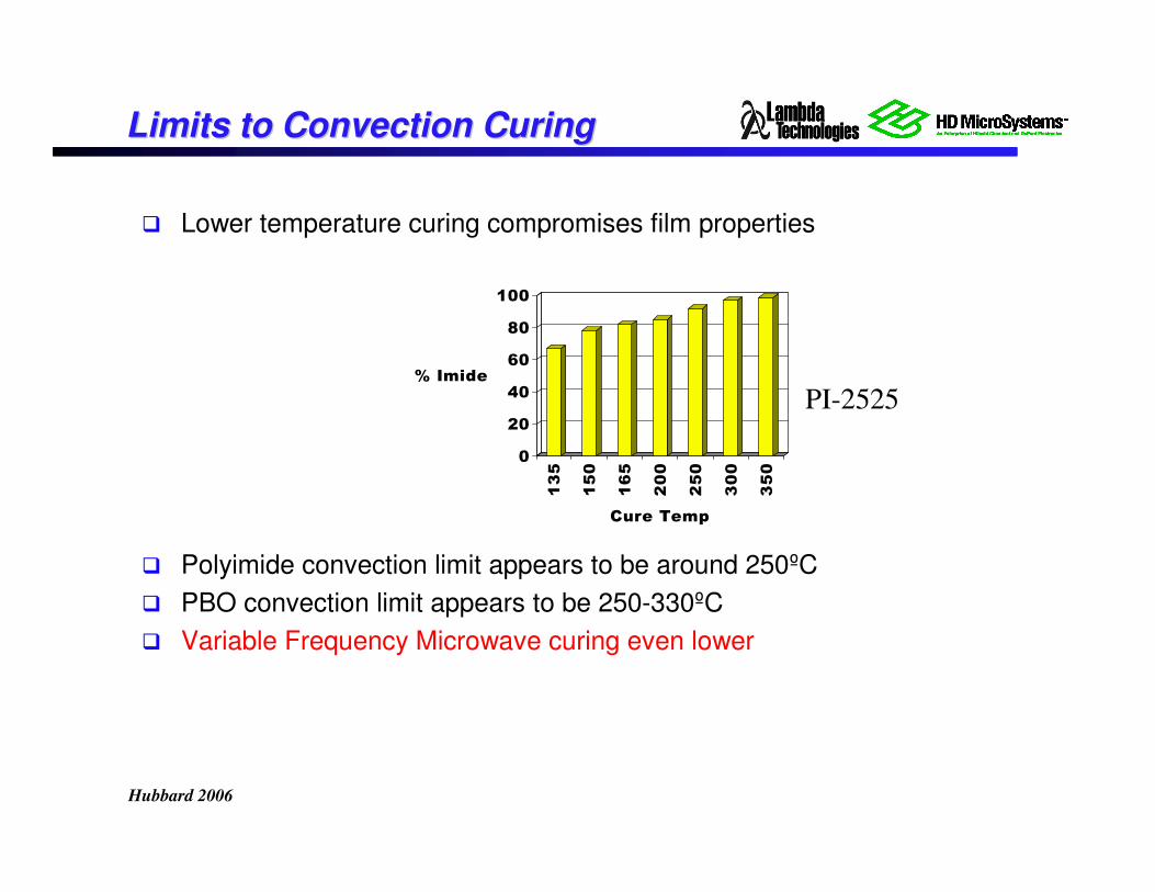
� Lower temperature curing compromises film properties
� Polyimide convection limit appears to be around 250ºC
� PBO convection limit appears to be 250-330ºC
� Variable Frequency Microwave curing even lower
0
20
40
60
80
100
% Imide
135
150
165
200
250
300
350
Cure Temp
PI-2525
Hubbard 2006
Characteristics of VFMCharacteristics of VFM
� Multiple frequencies excite a large number of
modes resulting in a uniform energy distribution
� Rapid frequency sweeping eliminates conditions
that can cause arcing on metal components
� Agile control and feedback for fast response
� Benign process to semiconductors
� 90 nm SRAM, DRAM, microprocessors, analog
� No change to device parameters or dopants
Hubbard 2006
Variable Frequency MicrowavesVariable Frequency Microwaves
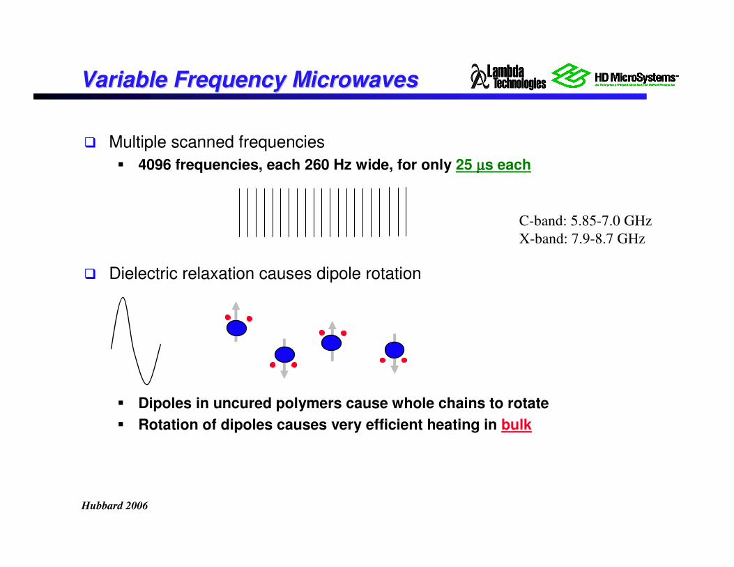
� Multiple scanned frequencies
� 4096 frequencies, each 260 Hz wide, for only 25 µµµµs each
� Dielectric relaxation causes dipole rotation
� Dipoles in uncured polymers cause whole chains to rotate
� Rotation of dipoles causes very efficient heating in bulk
C-band: 5.85-7.0 GHz
X-band: 7.9-8.7 GHz
Hubbard 2006
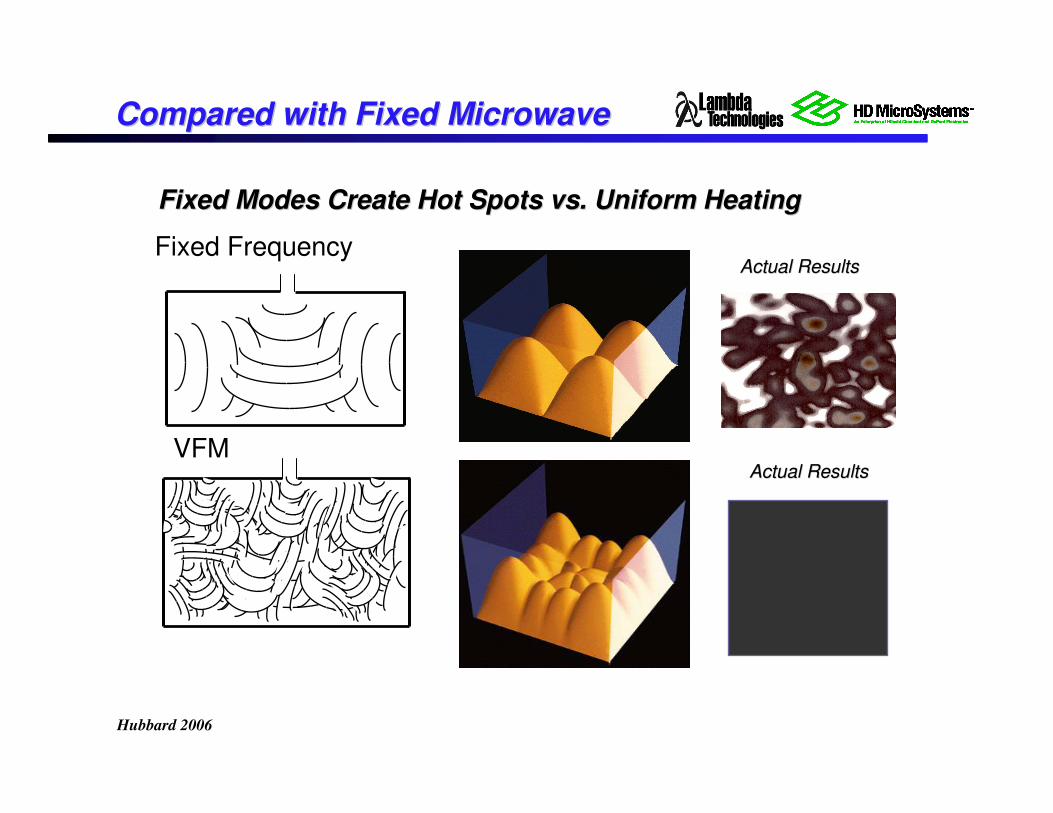
Fixed Modes Create Hot Spots vs. Uniform HeatingFixed Modes Create Hot Spots vs. Uniform Heating
Actual ResultsActual Results
Actual ResultsActual Results
Fixed Frequency
VFM
Compared with Fixed MicrowaveCompared with Fixed Microwave
Hubbard 2006
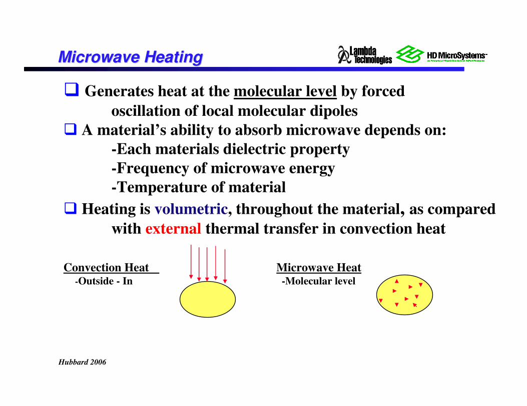
� Generates heat at the molecular level by forced
oscillation of local molecular dipoles
� A material’s ability to absorb microwave depends on:
-Each materials dielectric property
-Frequency of microwave energy
-Temperature of material
� Heating is volumetric, throughout the material, as compared
with external thermal transfer in convection heat
Convection Heat Microwave Heat-Outside - In -Molecular level
Microwave HeatingMicrowave Heating
Hubbard 2006
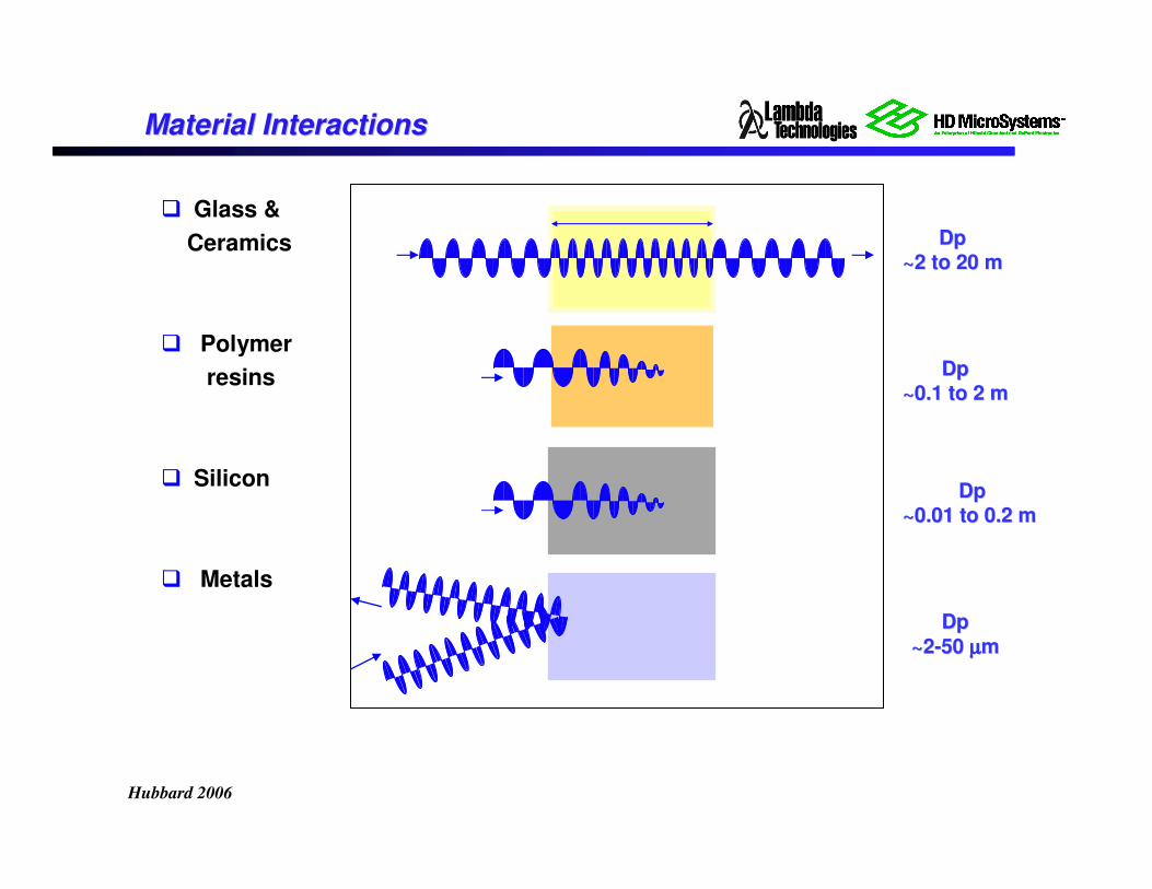
Material InteractionsMaterial Interactions
� Glass &
Ceramics
� Polymer
resins
� Silicon
� Metals
DpDp
~2 to 20 m~2 to 20 m
DpDp
~2~2--50 50 µµµµµµµµmm
DpDp
~0.01 to 0.2 m ~0.01 to 0.2 m
DpDp
~0.1 to 2 m~0.1 to 2 m
Hubbard 2006
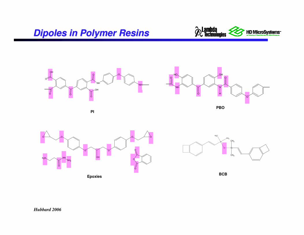
Dipoles in Polymer ResinsDipoles in Polymer Resins
PI
N
H
O
O
OH
O
OH
NH
OO
O O
O
O
OH
NH
O
NH2
OH
Si
O Si
CH3
CH3
CH3
CH3
BCB
PBO
Epoxies
O O
O
OH
O
O O
NH2
O
NH
NH2O
O
O
Hubbard 2006
Polymerization MechanismsPolymerization Mechanisms
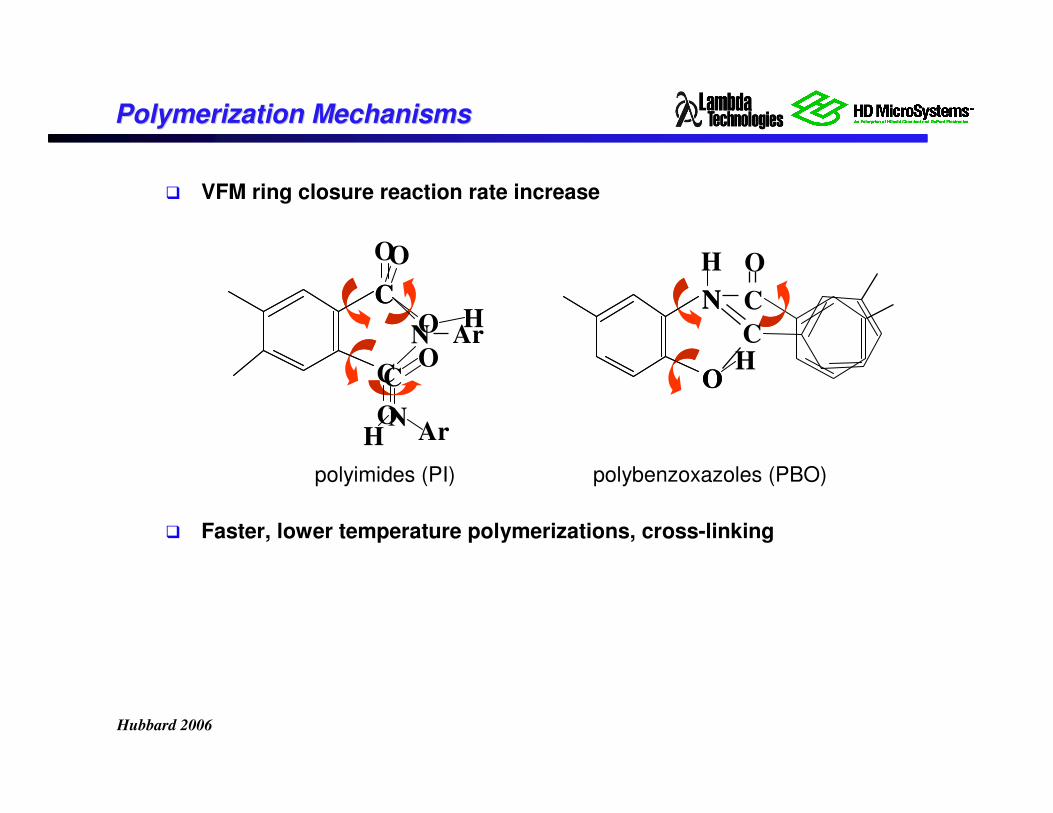
� VFM ring closure reaction rate increase
polyimides (PI) polybenzoxazoles (PBO)
� Faster, lower temperature polymerizations, cross-linking
C
O
OH
H
NC
N
O
CO
O H
ArH
C
N
O
C
O
Ar C
O
N
Hubbard 2006
Previous Polyimide ResultsPrevious Polyimide Results
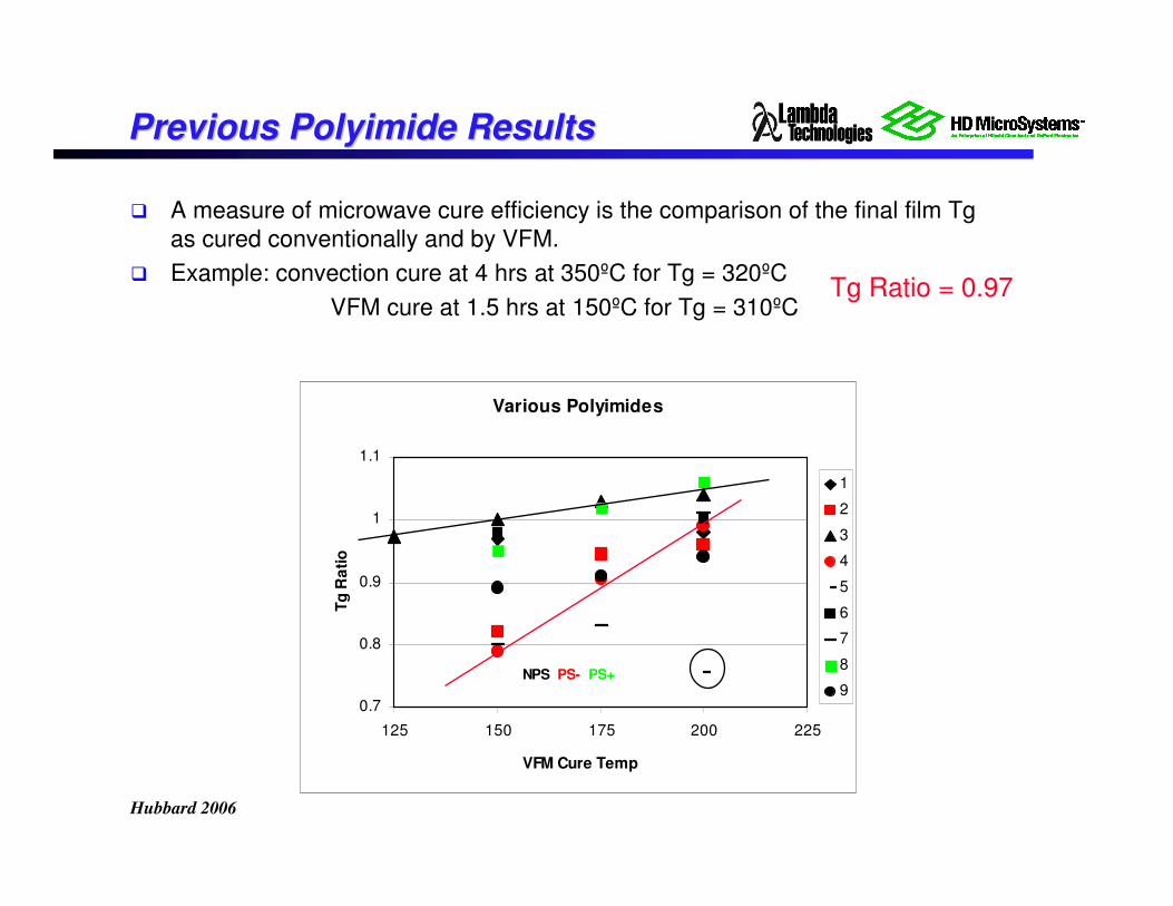
� A measure of microwave cure efficiency is the comparison of the final film Tg
as cured conventionally and by VFM.
� Example: convection cure at 4 hrs at 350ºC for Tg = 320ºC
VFM cure at 1.5 hrs at 150ºC for Tg = 310ºCTg Ratio = 0.97
Various Polyimides
0.7
0.8
0.9
1
1.1
125 150 175 200 225
VFM Cure Temp
Tg
Ra
tio
1
2
3
4
5
6
7
8
9NPS PS- PS+
Hubbard 2006
Electronic CorrelationsElectronic Correlations
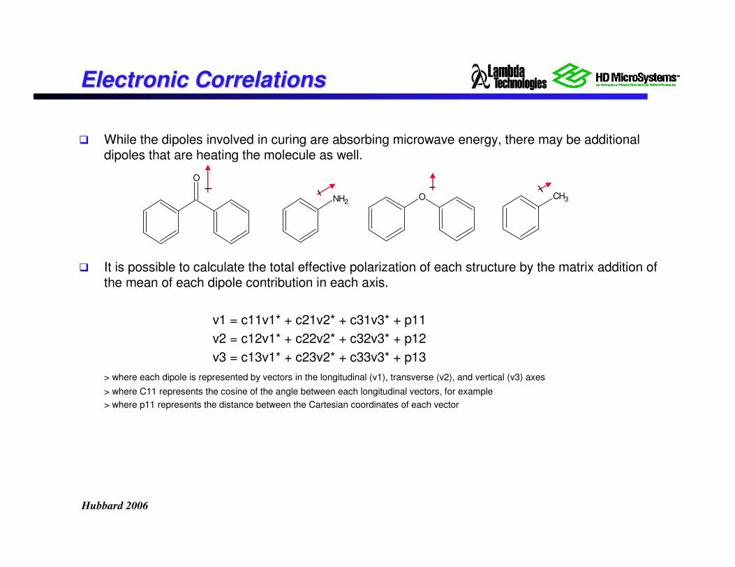
� While the dipoles involved in curing are absorbing microwave energy, there may be additional dipoles that are heating the molecule as well.
� It is possible to calculate the total effective polarization of each structure by the matrix addition of the mean of each dipole contribution in each axis.
v1 = c11v1* + c21v2* + c31v3* + p11
v2 = c12v1* + c22v2* + c32v3* + p12
v3 = c13v1* + c23v2* + c33v3* + p13
> where each dipole is represented by vectors in the longitudinal (v1), transverse (v2), and vertical (v3) axes
> where C11 represents the cosine of the angle between each longitudinal vectors, for example
> where p11 represents the distance between the Cartesian coordinates of each vector
O
CH3NH2O
Hubbard 2006
Electronic CorrelationsElectronic Correlations
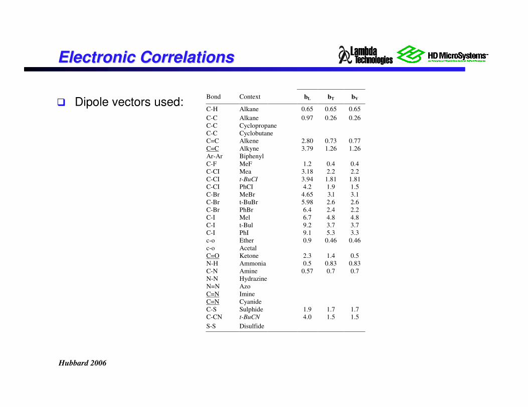
� Dipole vectors used:Bond Context bL bT bV
C-H Alkane 0.65 0.65 0.65
C-C Alkane 0.97 0.26 0.26
C-C Cyclopropane
C-C Cyclobutane
C=C Alkene 2.80 0.73 0.77
C=C Alkyne 3.79 1.26 1.26
Ar-Ar Biphenyl
C-F MeF 1.2 0.4 0.4
C-CI Mea 3.18 2.2 2.2
C-CI t-BuCI 3.94 1.81 1.81
C-CI PhCI 4.2 1.9 1.5
C-Br MeBr 4.65 3.l 3.1
C-Br t-BuBr 5.98 2.6 2.6
C-Br PhBr 6.4 2.4 2.2
C-I Mel 6.7 4.8 4.8
C-I t-Bul 9.2 3.7 3.7
C-I PhI 9.1 5.3 3.3
c-o Ether 0.9 0.46 0.46
c-o Acetal
C=O Ketone 2.3 1.4 0.5
N-H Ammonia 0.5 0.83 0.83
C-N Amine 0.57 0.7 0.7
N-N Hydrazine
N=N Azo
C=N Imine
C=N Cyanide
C-S Sulphide 1.9 1.7 1.7
C-CN t-BuCN 4.0 1.5 1.5
S-S Disulfide
Hubbard 2006
0.60
0.70
0.80
0.90
1.00
1.10
0.00 1.00 2.00 3.00 4.00 5.00
Polarizability (Debye)
Tg
rati
o
q
mn
o
p
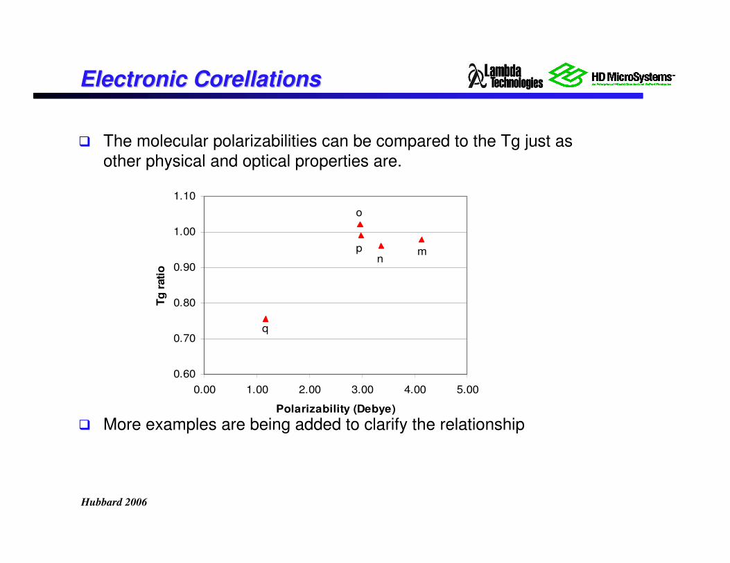
Electronic Electronic CorellationsCorellations
� The molecular polarizabilities can be compared to the Tg just as
other physical and optical properties are.
� More examples are being added to clarify the relationship
Hubbard 2006
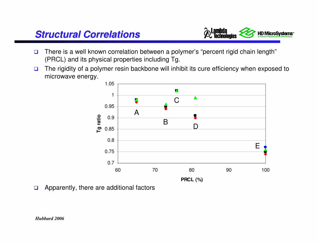
Structural CorrelationsStructural Correlations
� There is a well known correlation between a polymer’s “percent rigid chain length”
(PRCL) and its physical properties including Tg.
� The rigidity of a polymer resin backbone will inhibit its cure efficiency when exposed to
microwave energy.
� Apparently, there are additional factors
0.7
0.75
0.8
0.85
0.9
0.95
1
1.05
60 70 80 90 100
PRCL (%)
Tg
rati
o
A
B
C
D
E
Hubbard 2006
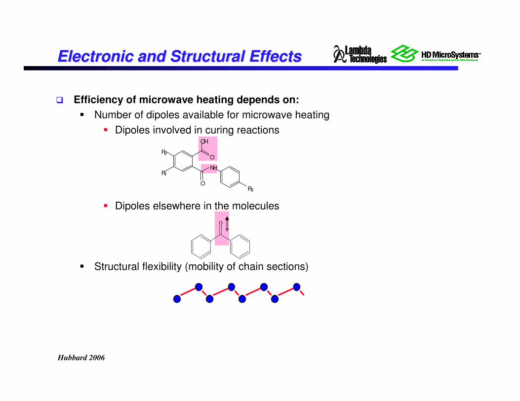
Electronic and Structural EffectsElectronic and Structural Effects
� Efficiency of microwave heating depends on:
� Number of dipoles available for microwave heating
� Dipoles involved in curing reactions
� Dipoles elsewhere in the molecules
� Structural flexibility (mobility of chain sections)
O
O
OH
O
NHR1
R2
R3
Hubbard 2006
Custom Design of Custom Design of PBOsPBOs
� Crosslinking more complex than linear PI
� Design options:
� Backbone: aromatic or alicyclic
� Chain endcap: dipole strength
� Cyclization promoter: yes or no
� Crosslinker: dipole strength
� Crosslinker: amount
� Process options:
� Temperature of soak: 170-200ºC
� Time of soak: 1-2 hrs.
� Ramp rate up to soak: 0.2-1.0 deg/s
� Solvent: NMP or GBL
� Design Matrix (DOE)
� Newly synthesized molecules
� Eight variables; 16 trials (28-5) with four center points
� Dipole strengths are not exact center points
� Confirmation experiments and photolithography
Hubbard 2006
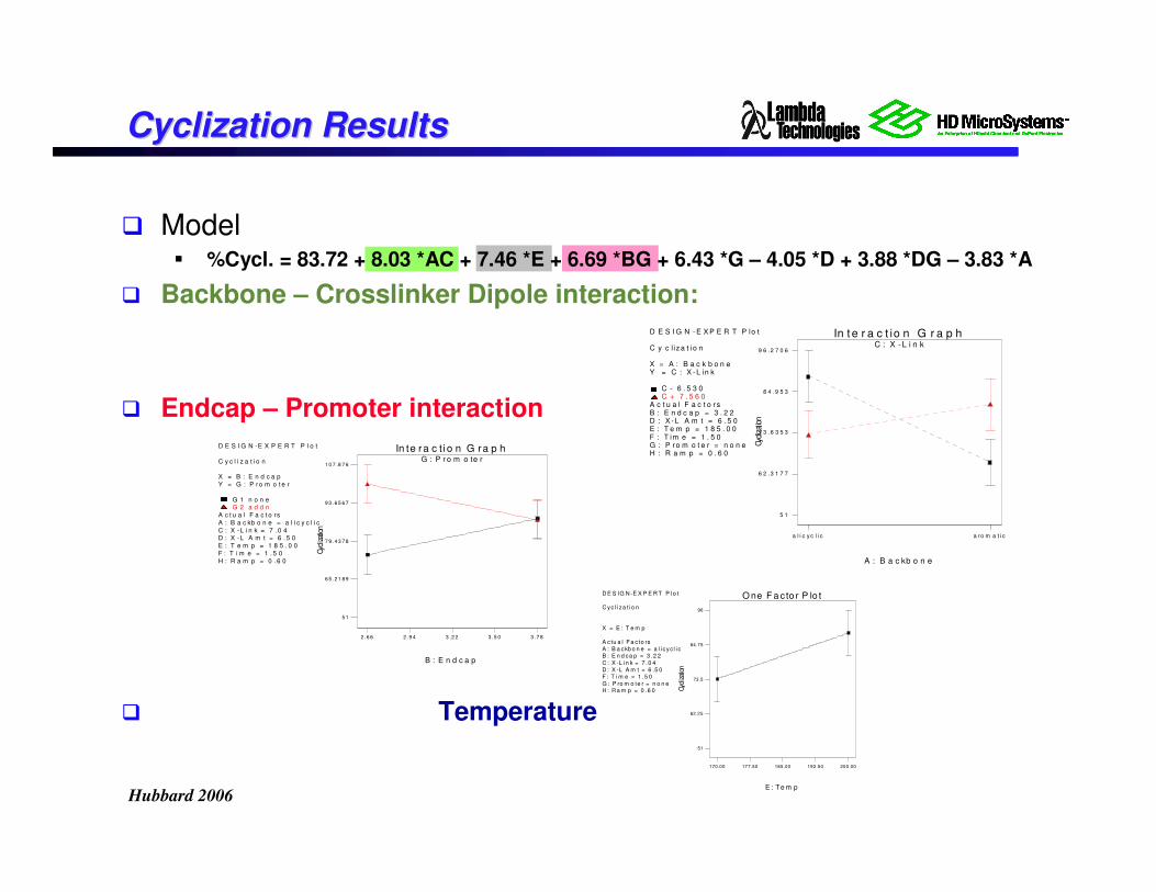
CyclizationCyclization ResultsResults
� Model� %Cycl. = 83.72 + 8.03 *AC + 7.46 *E + 6.69 *BG + 6.43 *G – 4.05 *D + 3.88 *DG – 3.83 *A
� Backbone – Crosslinker Dipole interaction:
� Endcap – Promoter interaction
� Temperature
D E S I G N - E X P E R T P lo t
C y c l iz a t io n
X = A : B a c k b o n eY = C : X - L in k
C - 6 . 5 3 0C + 7 . 5 6 0
A c t u a l F a c t o r sB : E n d c a p = 3 . 2 2D : X - L A m t = 6 . 5 0E : T e m p = 1 8 5 . 0 0F : T im e = 1 . 5 0G : P r o m o t e r = n o n eH : R a m p = 0 . 6 0
C : X -L i n k
In t e r a c t io n G r a p h
A : B a c kb o n e
Cyc
lizat
ion
a l i c y c l i c a ro m a t i c
5 1
6 2 .3 1 7 7
7 3 .6 3 5 3
8 4 .9 5 3
9 6 .2 7 0 6
D E S I G N -E X P E R T P l o t
C y c l i z a t i o n
X = B : E n d c a p
Y = G : P ro m o t e r
G 1 n o n eG 2 a d d n
A c t u a l F a c t o rs
A : B a c kb o n e = a l i c y c l i c
C : X -L i n k = 7 . 0 4D : X -L A m t = 6 . 5 0
E : T e m p = 1 8 5 . 0 0
F : T i m e = 1 . 5 0
H : R a m p = 0 . 6 0
G : P r o m o te r
In te ra c ti o n G ra p h
B : E n d c a p
Cyc
lizat
ion
2 .6 6 2 .9 4 3 .2 2 3 .5 0 3 .7 8
5 1
6 5 .2 1 8 9
7 9 .4 3 7 8
9 3 .6 5 6 7
1 0 7 .8 7 6
D E S IG N -E X P E R T P l o t
C yc l i za t i o n
X = E : T e m p
A c tu a l F a c to rs
A : B a ckb o n e = a l i c yc l i cB : E n d ca p = 3 .2 2
C : X -L i n k = 7 .0 4
D : X -L A m t = 6 .5 0F : T i m e = 1 .5 0
G : P ro m o te r = n o n eH : R a m p = 0 .6 0
170.00 177.50 185.00 192.50 200.00
51
62.25
73.5
84.75
96
E : Te m p
Cyc
lizat
ion
O ne F a c to r P lo t
Hubbard 2006
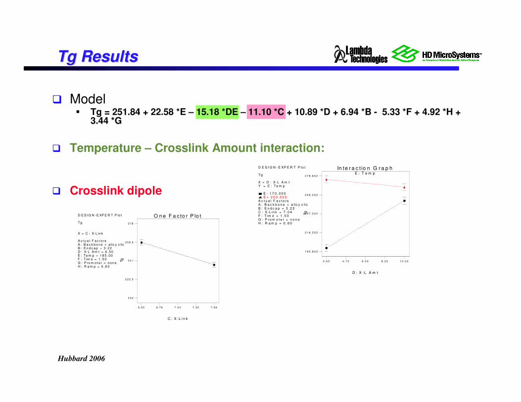
TgTg ResultsResults
� Model� Tg = 251.84 + 22.58 *E – 15.18 *DE – 11.10 *C + 10.89 *D + 6.94 *B - 5.33 *F + 4.92 *H +
3.44 *G
� Temperature – Crosslink Amount interaction:
� Crosslink dipole
D E S I G N -E XP E R T P lo t
T g
X = D : X-L A m tY = E : T e m p
E - 1 7 0 . 0 0 0E + 2 0 0 . 0 0 0
A c t u a l F a c t o rsA : B a c k b o n e = a lic y c licB : E n d c a p = 3 . 2 2C : X-L in k = 7 . 0 4F : T im e = 1 . 5 0G : P ro m o t e r = n o n eH : R a m p = 0 . 6 0
E : T e m p
In te r a c t io n G r a p h
D : X -L A m t
Tg
3 .0 0 4 .7 5 6 .5 0 8 .2 5 1 0 .0 0
1 9 5 .8 0 3
2 1 6 .5 5 2
2 3 7 .3 0 2
2 5 8 .0 5 2
2 7 8 .8 0 2
D E S I G N -E XP E R T P lo t
Tg
X = C : X-L in k
A c t u a l F a c t o rsA : B a c k b o n e = a lic y c licB : E n d c a p = 3 . 2 2D : X-L A m t = 6 . 5 0E : Te m p = 1 8 5 . 0 0F : T im e = 1 . 5 0G : P ro m o t e r = n o n eH : R a m p = 0 . 6 0
6 .5 3 6 .7 9 7 .0 4 7 .3 0 7 .5 6
2 0 4
2 2 2 .5
2 4 1
2 5 9 .5
2 7 8
C : X -L i n k
Tg
O n e F a c to r P lo t
Hubbard 2006
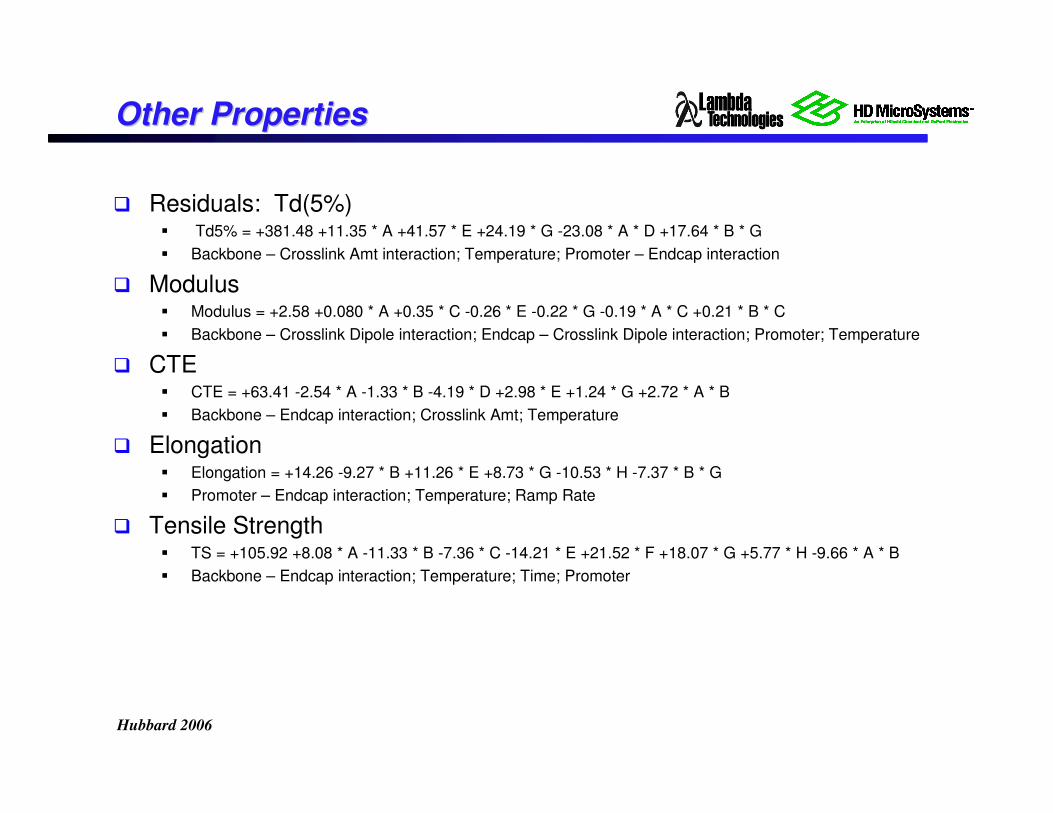
Other PropertiesOther Properties
� Residuals: Td(5%)� Td5% = +381.48 +11.35 * A +41.57 * E +24.19 * G -23.08 * A * D +17.64 * B * G
� Backbone – Crosslink Amt interaction; Temperature; Promoter – Endcap interaction
� Modulus� Modulus = +2.58 +0.080 * A +0.35 * C -0.26 * E -0.22 * G -0.19 * A * C +0.21 * B * C
� Backbone – Crosslink Dipole interaction; Endcap – Crosslink Dipole interaction; Promoter; Temperature
� CTE� CTE = +63.41 -2.54 * A -1.33 * B -4.19 * D +2.98 * E +1.24 * G +2.72 * A * B
� Backbone – Endcap interaction; Crosslink Amt; Temperature
� Elongation� Elongation = +14.26 -9.27 * B +11.26 * E +8.73 * G -10.53 * H -7.37 * B * G
� Promoter – Endcap interaction; Temperature; Ramp Rate
� Tensile Strength� TS = +105.92 +8.08 * A -11.33 * B -7.36 * C -14.21 * E +21.52 * F +18.07 * G +5.77 * H -9.66 * A * B
� Backbone – Endcap interaction; Temperature; Time; Promoter
Hubbard 2006
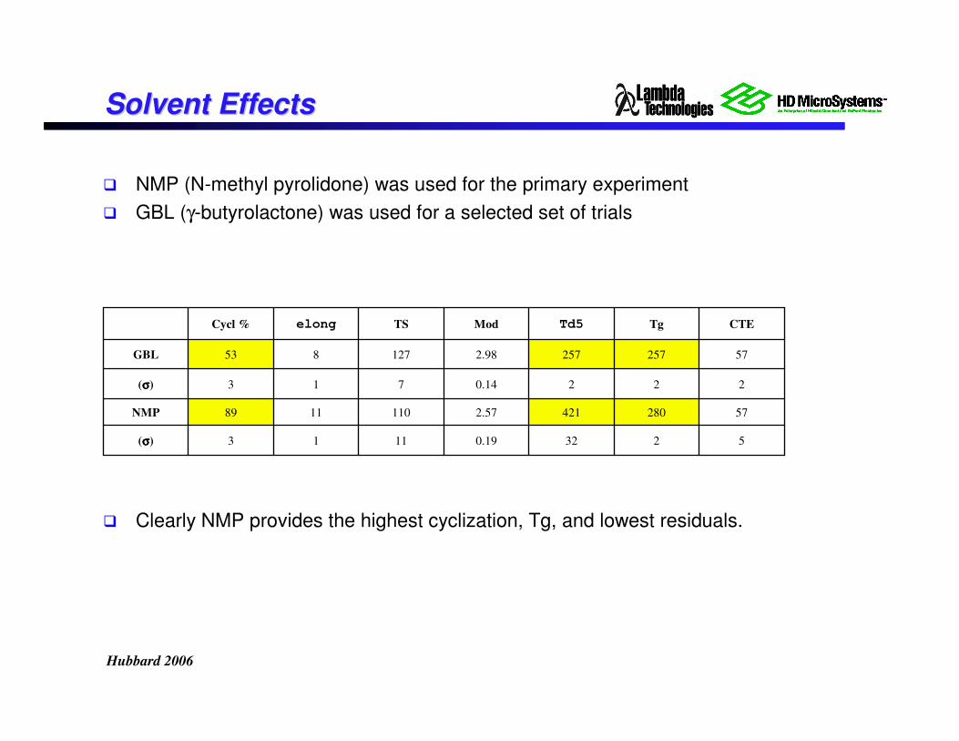
Solvent EffectsSolvent Effects
� NMP (N-methyl pyrolidone) was used for the primary experiment
� GBL (γ-butyrolactone) was used for a selected set of trials
� Clearly NMP provides the highest cyclization, Tg, and lowest residuals.
52320.191113(σσσσ)
572804212.571101189NMP
2220.14713(σσσσ)
572572572.98127853GBL
CTETgTd5ModTSelongCycl %
Hubbard 2006
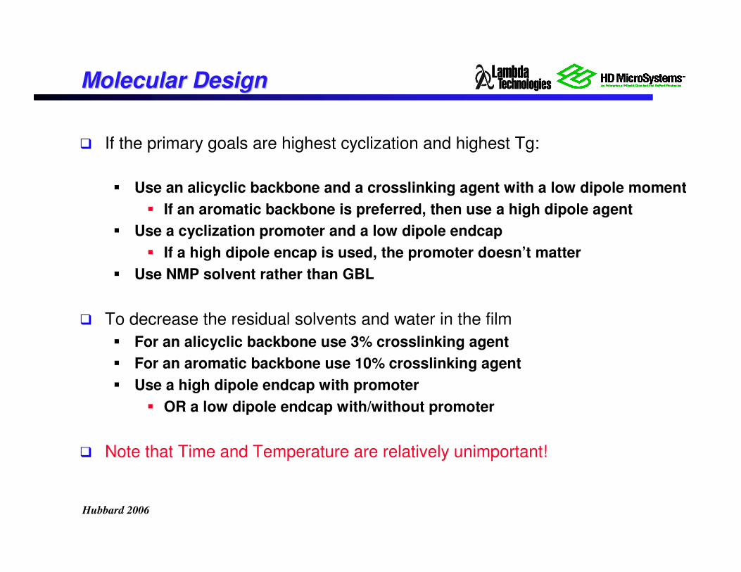
Molecular DesignMolecular Design
� If the primary goals are highest cyclization and highest Tg:
� Use an alicyclic backbone and a crosslinking agent with a low dipole moment
� If an aromatic backbone is preferred, then use a high dipole agent
� Use a cyclization promoter and a low dipole endcap
� If a high dipole encap is used, the promoter doesn’t matter
� Use NMP solvent rather than GBL
� To decrease the residual solvents and water in the film
� For an alicyclic backbone use 3% crosslinking agent
� For an aromatic backbone use 10% crosslinking agent
� Use a high dipole endcap with promoter
� OR a low dipole endcap with/without promoter
� Note that Time and Temperature are relatively unimportant!
Hubbard 2006
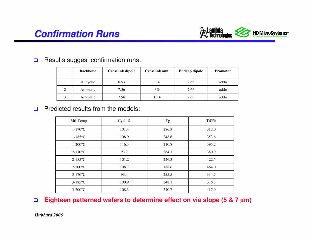
Confirmation RunsConfirmation Runs
� Results suggest confirmation runs:
� Predicted results from the models:
� Eighteen patterned wafers to determine effect on via slope (5 & 7 µµµµm)
addn2.6610%7.56Aromatic3
addn2.663%7.56Aromatic2
addn2.663%6.53Alicyclic1
PromoterEndcap dipoleCrosslink amt.Crosslink dipoleBackbone
417.9240.7108.33-200°C
376.3248.1100.93-185°C
334.7255.593.43-170°C
464.0188.6108.72-200°C
422.5226.3101.22-185°C
380.9264.193.72-170°C
395.2210.8116.31-200°C
353.6248.6108.91-185°C
312.0286.3101.41-170°C
Td5%TgCycl. %Mtl-Temp
Hubbard 2006
SummarySummary
� PBO polymers can be custom synthesized for:
� Low temperature curing with VFM
� Unique mechanical properties
� As a result of the low temperature – fast cure
� As a result of the uniform bulk cure of VFM
� Next steps
� Analysis of confirmation/photolithography runs
� Further refinement and selection of structures
� Feedback from users of PBO films for passivation and WLP
� Investigation of epoxy materials in progress