Embed Size (px)
Citation preview

I n t r o d u c t i o nAlongside the progress in fire safety engineering in building design, comes the requirement for electrical installations to provide increasingly greater fire protection for buildings and a safer environment for the people who use them. Ducab has made a major contribution to meeting these requirements, with the development of a range of Ducab Smokemaster Low Smoke Zero Halogen armoured power and wiring cables.
For installation guidelines please refer to our Cable & Drum Handling Guideline handbook.
This brochure provides product information and technical data for the Ducab Smokemaster range of Cables

... Helping you see more clearly 1
Go to Contents Page
Contents
Introduction IFC
Low Smoke Zero Halogen Cables – Why? 2
Typical Applicationsand Performance Standards 4 – 5
Specification Guidelines 6 – 7
Quality Management at Ducab 8
Ducab SmokemasterConduit Wiring Cablesto BS 7211 9
Ducab SmokemasterArmoured Cables to BS 6724 10
Technical Data 11 – 15
Ducab Connect Componentsand Cable Accessories 16 – 17
... Helping you see more clearly

2
Go to Contents Page
All buildings and structures are at risk from fire and so are the people who use them.
The threat which a fire poses isn’t confined to the flames and the heat. Smoke, fumes and acid gases produced from the many items within a building’s structure, fabric and fittings can spread quickly during a fire.
The structural services of the building, including the underfloor voids and vertical riser ducts which accommodate cables, can aid the spread of fire and the spread of the smoke and fumes which the fire produces.
These essential structural features form natural draught corridors which spread the problem of smoke and fumes to areas of the building which may not be affected by the fire itself – putting people at risk.
Installing Ducab Smokemaster cables can reduce the threat to life by extending the escape and rescue time available.
Smoke diminishes the time available by reducing visibility, hindering mobility and causing bodily harm.
Corrosive acids are formed when the gases released by fire come into contact with moisture. The moisture could be in the air, or could be generated by automatic sprinkler systems. Acid gases are poisonous irritants to people inhaling them. They also attack the electronic circuitry of sophisticated equipment used in modern offices causing costly damage. Ducab Smokemaster does not produce acid gas.
Ducab Smokemaster cables provide improved fire protection and reduce the risk to building occupants. They are slow to ignite, burn slowly and most importantly, give out negligible amounts of smoke and fumes during a fire.
Much more time is available to enable the orderly evacuation of people from buildings when a fire is discovered. Besides the time needed for people to evacuate a building, extra time is essential to the emergency services personnel who have to enter the building to control and extinguish the fire and assist those needing help.
Low Smoke Zero Halogen Cables – Why?
Previous Page | Next Page

... Helping you see more clearly 3
Go to Contents Page
Ducab Smokemaster cables • improve safety and human survival in a fire
• allow people to see and breathe safely for longer
• increase time for people to escape
• improve visibility and safety for emergency services
• reduce fire damage of buildings and electronic equipment
• are designed to improve public and environmental safety
Specially conducted fire tests have confirmed the performance advantage of Ducab Smokemaster
Exit and escapelights obscured by
dense smoke,hindering escape.
PVC Cable Ducab Smokemaster cable
Ducab Smokemaster cables resist ignition- extending the time before cables start to burn in a fire, providing more time to escape.
Ducab Smokemaster cables reduce fire propagation- by bing slow to burn, reducing the immediate threat and extending escape time.
Ducab Smokemaster cables reduce smoke to a minimum - reducing disorientation, confusion and panic. With little smoke, people can see the EXIT routes clearly and have more time to follow them to safety. Emergency services have more time to operate effectively.
Ducab Smokemaster cables do not contain halogens - hydrochloric acid is not formed during a fire. There is no threat of inhalation of this highly irritant chemical and no damage to sensitive or costly equipment.
Exit and escapelights allowing safer
evacuation.
Fire Test after 6 minutes
Previous Page | Next Page

4
Go to Contents Page
Involving high security
Defence installationsPrisonsResearch EstablishmentsComputer Centres
Typical Applications
Places which are regularly densely populated
Housing people with lim-ited mobility
Where people are unfamiliar with a building’s layout
Involving valuable equipment
Computer SuitesDefence InstallationsResearch LaboratoriesTelecommunications Centres
HotelsCommercial OfficesMulti-Storey DwellingsPublic Buildings
HospitalsClinicsCare HomesRetirement Homes
Shopping MallsCinemas and TheatresAirports
Previous Page | Next Page

... Helping you see more clearly 5
Go to Contents Page
Performance Standards
Emirates Towers Dubai
One of the safest buildings in Dubai thanks toDucab Smokemastercables
All Ducab Smokemaster products are manufactured to comply with the following fire safety standards:
Flame Propagation Ducab Smokemaster armoured cables are flame retardant and comply with BS EN 50266/IEC 60332-3.
Ducab Smokemaster wiring cables comply with BS EN 60332 and IEC 60332-1.
Acid Gas Emissions
IEC 60754 Part 1 & Part 2 define the tests for detecting hagen acid gas emissions from burning materials taken from cables. Ducab Smokemaster cables comply with these halogen free emission standards when exposed to fire.
Smoke Emission
Ducab Smokemaster cables comply with the smoke emission requirements of IEC 61034.
Previous Page | Next Page

6
Go to Contents Page
Specification Guidelines
Multi-storey Buildings
Heavily populatedwith people
Frequent visitorsto the building
Design Considerations
A typical multi-storey public building will include many different rooms and facilities including bedrooms, kitchens, communal living and dining areas.
Some floors may be densely populated. There may be visitors who will not be familiar with a building’s layout,and there may be people with limited mobility.
A number of circuits are required for lighting and power supply.Ducab Smokemaster cables can be specified for all these applications, so that people in all parts of the building have longer to evacuate in the event of a fire.
Previous Page | Next Page
... Helping you see more clearly 7
Go to Contents Page
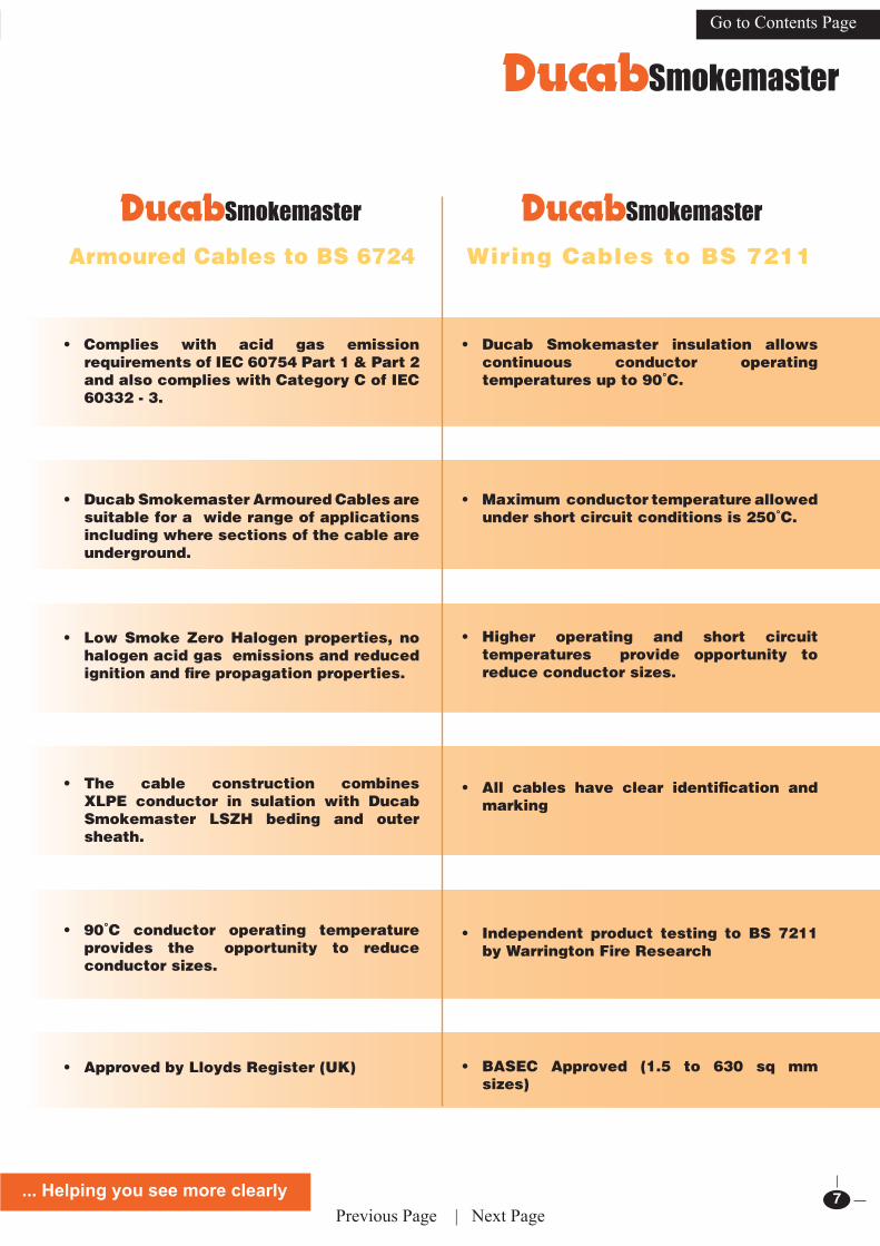
Wiring Cables to BS 7211Armoured Cables to BS 6724
• Ducab Smokemaster insulation allows continuous conductor operating temperatures up to 90˚C.
• Maximum conductor temperature allowed under short circuit conditions is 250˚C.
• Higher operating and short circuit temperatures provide opportunity to reduce conductor sizes.
• All cables have clear identification and marking
• Independent product testing to BS 7211 by Warrington Fire Research
• BASEC Approved (1.5 to 630 sq mm sizes)
• Complies with acid gas emission requirements of IEC 60754 Part 1 & Part 2 and also complies with Category C of IEC 60332 - 3.
• Ducab Smokemaster Armoured Cables are suitable for a wide range of applications including where sections of the cable are underground.
• Low Smoke Zero Halogen properties, no halogen acid gas emissions and reduced ignition and fire propagation properties.
• The cable construction combines XLPE conductor in sulation with Ducab Smokemaster LSZH beding and outer sheath.
• 90˚C conductor operating temperature provides the opportunity to reduce conductor sizes.
• Approved by Lloyds Register (UK)
Previous Page | Next Page

8
Go to Contents Page
The definition of quality in Ducab goes far beyond the conformance of product to specified requirements. Ducab is committed to providing the customer with total quality excellence of product and service that fully meets expectations and is superior in value to that which can be obtained elsewhere.
Since its inception, Ducab has an unrivaled reputation for quality in the region. For many years the company has worked to raise quality awareness in Dubai and throughout the Gulf. The
company’s Quality Management System was certified to ISO 90001 in 1994 and upgraded in 2002 to the new, more stringent ISO 9001:2000 standard certified by BASEC, a reputed UKAS accredited certification body specializing in the cable industry. Ducab was the first cable company in the Middle East to achieve this distinction.
Ducab is also the first manufacturing company in the Middle East to obtain the ISO 14001 enviornmental certification, and certified by BASEC.
Ducab’s excellence in quality was recognized when the company was awarded the Dubai Qulaity Award, in the very first year of its inception, in 1994. Ducab has also won the DQA-Gold award again in 1998 and 2004.
TESTING FACILITIESDucab is the only cable manufacturer in the
Middle East to have invested in fire testing facilities for fire performance cables and also uses external, independent test houses including Warrington Fire Research in the United Kingdom to test product, to ensure conformance to the relevant standards.
Ducab has invested in the state-of-the-art technology for the testing of cables in fire and has a purpose-built testing facility which includes a 3 metre cube test of smoke density to IEC 61034 – 1 & 2, and a vertical ladder fire test chamber to IEC 60332 –3.
Quality Management at Ducab
Ducab: Where Quality is a Way of Life
Previous Page | Next Page

... Helping you see more clearly 9
Go to Contents Page
Nominal
Conductor
Area
Radial
Thickness of
Insualtion
Mean Overall
Diameter
(Upper limit)
Approximate
Cable Weight
Maximum
conductor
Resistance at
20ºC
Enclosed in Conduit (method 3)
Two Cables,
Single
Phase a.c.
Current Rating
Two Cables,
Single Phase
a.c. Volt Drop
per amp per
metre
Three or Four
Cables, Three
Phase a.c.
Current Rating
Three or Four
Cables, Three
Phase a.c. Volt
Drop per Amp
per Metre
mm2 mm mm kg/km ohm/km amp mV/A/m amp mV/A/m
1.5 0.7 3.4 22 12.1 22 31 19 27
2.5 0.8 4.1 33 7.41 30 19 26 16
4 0.8 4.7 49 4.61 40 12 35 10
6 0.8 5.4 69 3.08 51 7.9 45 6.8
10 1.0 7.0 116 1.83 71 4.7 63 4.0
16 1.0 8.0 175 1.15 95 2.9 85 2.5
25 1.2 10.1 274 0.727 126 1.90 111 1.65
35 1.2 11.3 367 0.524 156 1.35 138 1.15
50 1.4 13.0 495 0.387 189 1.05 168 0.90
70 1.4 15.0 699 0.268 240 0.75 214 0.65
95 1.6 17.0 968 0.193 290 0.58 259 0.50
120 1.6 19.0 1164 0.153 336 0.48 299 0.42
150 1.8 21.0 1413 0.124 375 0.43 328 0.37
185 2.0 23.5 1828 0.0991 426 0.37 370 0.32
240 2.2 26.5 2320 0.0754 500 0.33 433 0.29
300 2.4 29.5 2988 0.0601 573 0.31 493 0.27
400 2.6 34.3 3700 0.0470 683 0.29 584 0.25
500 2.8 38.2 4750 0.0366 783 0.28 666 0.24
630 2.8 42.5 6000 0.0283 900 0.27 764 0.23
Table 1 Ducab Smokemaster Wiring Cables 450/750V Grade
Technical DataDucab Smokemaster Wiring Cables to BS 7211
ConstructionStranded plain annealed copper single core conductors insulated with crosslinked Ducab Smokemaster Compound. Voltage Grade: 450/750V.
IdentificationDucab Smokemaster Wiring Cables are identified with the legend – BICC Ducab Smokemaster LSZH BS 7211 Z – and are available as standard in Red, Black, Yellow, Blue and Green/Yellow colours. Other colours can be manufactured to order.
InstallationThe cables are primarily intended for installation in conduit or trunking.
Current RatingsThe following ratings apply to cables bunched and enclosed in conduit on a wall, or enclosed in trunking, and are based on an ambient temperature of 30˚C.
Previous Page | Next Page

10
Go to Contents Page
ConstructionCircular or shaped stranded plain annealed copper conductors1, XLPE insulated, LSZH bedded, galvanised steel wire armoured2 and LSZH sheathed.Voltage grades 600/1000V and 1900/3300V.1 Aluminium conductors also available on some sizes.2 Aluminium armour on single core cables.
IdentificationCore Colours: Single - Red or BlackTwo - Red, BlackThree - Red, Yellow, Blue Four - Red, Yellow, Blue, Black Five - Red, Yellow, Blue, Black, Green/YellowSix and Above - White, printed with Black numerals
Sheath: Black as standard.Power/Control cables up to five cores are embossed with the legend - BS 6724 ELECTRIC CABLE 600/1000V(or 3300V as appropriate) BICC Ducab Smokemaster LSZH.
Multicore auxiliary cables are marked with the legend - BS 6724 ELECTRIC CABLE 600/1000V AUX BICC Ducab Smokemaster LSZH.
InstallationDucab Smokemaster armoured cables are primarily intended for installation in air. To avoid risk of damage during handling they should not be installed in temperatures lower than minus 10˚C. Cables with copper conductors should not be bent during installation to radii less than 6 x overall diameter. (Shaped conductors 8 x overall diameter).
Ducab Smokemaster armoured cables combine the excellence of cross linked polyethylene (XLPE) insulation with Low Smoke Zero Halogen materials as the bedding and outer sheath.
This material is notable for the absence of smoke-generating constituents, particularly halogens (fluorine, bromine, chlorine) thus avoiding the hazards of corrosive and noxious fumes emitted by standard materials such as PVC when exposed to flames.
These cables are developed and manufactured to pass large-scale vertical fire-propagation tests in British and International (IEC) standards. In the three-metre cube smoke emission test they perform to exacting standards.
They are free of added halogens so that acid gas emissions are not detectable when tested to IEC 60754 Part 1 & Part 2. The completed cables comply with Category C of IEC 60332-3.
Ducab Smokemaster armoured cables can be used in place of standard PVC insulated armoured cables but can operate continuously at 90˚C which means they have higher current and short circuit ratings than conventional PVC insulated armoured cables. As a result it may be possible to use a smaller conductor size.
Technical Data
Ducab Smokemaster Armoured Cables to BS 6724
Previous Page | Next Page

... Helping you see more clearly 11
Go to Contents Page
Conductor
Area
Approximate Diameter Approximate
cable Wt.
Maximum
armour
resistance at
20ºC
Maximum
conductor
resistance at
20ºC
Free air (Method 13)
Under
Armour
Armour
wire Dia
Overall Current
Rating
Volt Drop
Per Amp
per Metre
mm2 mm mm mm kg/km Ohm/km Ohm/km Amp mV/A/m
V Copper Power and Control Cables 600/1000 Single phase a.c or d.c
*1.5 7.8 0.9 12.0 285 10.2 12.1 29 31
2.5* 9.1 0.9 13.0 340 8.8 7.41 39 19
*4 9.7 0.9 14.0 410 7.9 4.61 52 12
*6 10.9 0.9 15.2 490 7.0 3.08 66 7.9
10* 13.0 0.9 17.5 640 6.0 1.83 90 4.7
*16 15.2 1.25 20.4 900 3.7 1.15 115 2.9
*25 18.5 1.25 24.1 1240 3.7 0.727 152 1.9
35* 21.5 1.6 27.7 1710 2.6 0.524 188 1.35
50 18.7 1.6 25.8 1800 2.3 0.387 228 1.00
70 21.5 1.6 29.0 2320 2.0 0.268 291 0.69
95 24.6 2.0 33.1 3150 1.4 0.193 354 0.52
120 26.8 2.0 36.1 3880 1.3 0.153 410 0.42
150 29.7 2.0 39.3 4820 1.2 0.124 472 0.35
185 33.3 2.5 44.7 5920 0.82 0.0991 539 0.29
240 38.1 2.5 49.0 7300 0.73 0.0754 636 0.24
300 42.3 2.5 53.5 8770 0.67 0.0601 732 0.21
400 47.6 2.5 58.2 10770 0.59 0.0470 847 0.19
Conductor
Area
Approximate Diameter Approx-
imate
cable Wt.
Maxi-
mum
armour
resistance
at 20ºC
Maximum
conductor
resistance
at 20ºC
Free air (Method 12)
Under
Armour
Armour
wire Dia
Overall Two cables vertical flat
spaced**a.c.
Three cables Trefoil
Touching
mm2 mm mm mm kg/km Ohm/km Ohm/km
Current
rating
Amp
Volt Drop
Per Amp
Per Metre
mV
Current
Rating
mV
Volt Drop
Per Amp
Per Metre
mV/A/m
V Copper Power Cables 600/1000
50 12.6 *1.6 18.4 800 1.30 0.387 266 1.00 222 0.87
70 14.5 1.6* 20.2 990 0.75 0.268 337 0.75 285 0.62
95 16.4 *1.6 22.3 1280 0.67 0.193 412 0.60 346 0.47
120 18.0 1.6* 24.2 1550 0.61 0.153 477 0.51 402 0.39
150 19.8 1.6 27.4 1900 0.42 0.124 539 0.45 463 0.33
185 22.0 1.6 30.0 2320 0.38 0.0991 614 0.40 529 0.28
240 24.6 1.6 32.8 2930 0.34 0.0754 714 0.35 625 0.24
300 27.3 1.6 36.6 3580 0.31 0.0601 805 0.32 720 0.21
400 31.2 2.0 40.5 4600 0.22 0.0470 889 0.30 815 0.195
500 36.0 2.0 44.2 5680 0.20 0.0366 989 0.29 918 0.180
630 40.0 2.0 48.8 7160 0.18 0.0283 1092 0.27 1027 0.170
800 45.8 2.5 55.4 9315 0.13 0.0221 1155 0.27 1119 0.165
1000 50.8 2.5 60.6 11490 0.12 0.0176 1238 0.25 1214 0.155
Table 2 Ducab Smokemaster Single Core Armoured cables 600/1000V Grade
Table 3 Ducab Smokemaster Two Core Armoured cables 600/1000V Grade
Installation conditions for above rating Ambient Air Temperature 30˚C Conductor operating temperature 90˚C
Technical Data
* Wire diameters are larger than those specified in BS 6724
** Adjacent surfaces separated by one cable diameter.Installation conditions for above ratingAmbient Air Temperature 30˚C Conductor operating temperature 90˚C
* Circular conductor all others are Sector shaped
Previous Page | Next Page

12
Go to Contents Page
Conductor
Area
Approximate Diameter Approximate
.cable Wt
Maximum
armour
resistance at
20ºC
Maximum
conductor
resistance at
20ºC
(Free air (Method 13
Under
Armour
Armour
wire Dia
Overall Current
Rating
Volt Drop
Per Amp
per Metre
mm2 mm mm mm kg/km Ohm/km Ohm/km Amp mV/A/m
V Copper Power and Control Cables 600/1000 Three phase a.c
1.5* 8.3 0.9 12.4 320 9.5 12.1 25 27
2.5* 9.6 0.9 13.5 390 8.2 7.41 33 16
4* 10.4 0.9 14.5 470 7.5 4.61 44 10
6* 11.6 0.9 16.0 565 6.7 3.08 56 6.8
10* 13.6 1.25 19.0 850 4.0 1.83 78 4.0
16* 16.0 1.25 21.6 1130 3.5 1.15 99 2.5
25* 20.0 1.6 26.7 1710 2.5 0.727 131 1.65
35* 22.7 1.6 29.4 2100 2.3 0.524 162 1.15
50 23.0 1.6 28.5 2450 2.0 0.387 197 0.87
70 26.0 1.6 32.2 3120 1.8 0.268 251 0.60
95 30.0 2.0 37.0 4310 1.3 0.193 304 0.45
120 32.8 2.0 40.4 5160 1.2 0.153 353 0.37
150 36.8 2.5 45.5 7160 0.78 0.124 406 0.30
185 41.5 2.5 49.8 8600 0.71 0.0991 463 0.26
240 46.0 2.5 55.1 10755 0.63 0.0754 546 0.21
300 51.5 2.5 60.2 13080 0.58 0.0601 628 0.185
400 56.4 2.5 66.6 15810 0.52 0.0470 728 0.165
Table 4 Ducab Smokemaster Three Core Armoured Cables 600/1000V Grade
Table 5 Ducab Smokemaster Four Core Armoured Cables 600/1000V Grade
Technical Data
Inst
alla
tion
con
diti
ons
for
rati
ng
Am
bien
t A
ir T
empe
ratu
re 3
0˚C
Con
duct
or o
pera
tin
g te
mpe
ratu
re 9
0˚C
* Circular conductor all others are Sector shaped
Conductor
Area
Approximate Diameter Approximate
.cable Wt
Maximum
armour
resistance at
20ºC
Maximum
conductor
resistance at
20ºC
(Free air (Method 13
Under
Armour
Armour
wire Dia
Overall Current
Rating
Volt Drop
Per Amp
per Metre
mm2 mm mm mm kg/km Ohm/km Ohm/km Amp mV
V Copper Power and Control Cables 600/1000 Three phase a.c
*1.5 9.1 0.9 13.5 380 8.8 12.1 25 27
*2.5 10.6 0.9 14.5 445 7.7 7.41 33 16
*4 11.4 0.9 17.0 550 6.8 4.61 44 10
*6 13.0 1.25 18.5 770 4.3 3.08 56 6.8
*10 15.0 1.25 20.5 1020 3.7 1.83 78 4.0
*16 18.0 1.25 23.5 1320 3.1 1.15 99 2.5
25 20.0 1.6 26.1 1840 2.3 0.727 131 1.65
35 22.8 1.6 28.6 2310 2.0 0.524 162 1.15
50 25.5 1.6 32.0 2970 1.8 0.387 197 0.87
70 29.5 2.0 37.7 4240 1.2 0.268 251 0.60
95 33.5 2.0 41.7 5400 1.1 0.193 304 0.45
120 37.5 2.5 47.1 7000 0.76 0.153 353 0.37
150 41.5 2.5 51.4 8350 0.68 0.124 406 0.30
185 46.0 2.5 56.6 10130 0.61 0.0991 463 0.26
240 52.5 2.5 63.0 12840 0.54 0.0754 546 0.21
300 57.5 2.5 68.8 15530 0.49 0.0601 628 0.185
400 65.0 3.15 78.1 19950 0.35 0.0470 728 0.165
Previous Page | Next Page

... Helping you see more clearly 13
Go to Contents Page
Conductor Area
Approximate Diameter Approximate cable wt.
Maximum armour resistance at 20ºC
Maximum conduc-tor resistance at
20ºC
Free air (Method 12)
Under Armour
Armour wireDia
Overall Current Rating
Ampsmm2 mm mm mm kg/km Ohm/km Ohm/km
V Copper Power Cables 1900/3300 Three cable in Trefoil
50 15.0 1.6* 20.6 810 0.75 0.387 228
70 16.6 1.6* 22.4 1040 0.67 0.268 285
95 18.4 1.6* 24.3 1330 0.61 0.193 350
120 19.8 1.6 27.2 1680 0.42 0.153 407
150 21.2 1.6 28.8 1970 0.39 0.124 463
185 23.0 1.6 30.8 2370 0.37 0.0991 528
240 25.5 1.6 33.5 2960 0.34 0.0754 623
300 27.7 1.6 36.1 3610 0.31 0.0601 710
400 31.0 2.0 40.5 4600 0.22 0.0470 808
500 36.0 2.0 44.2 5680 0.20 0.0366 915
630 40.0 2.0 48.8 7160 0.18 0.0283 1030
800 45.8 2.5 55.4 9150 0.13 0.0221 1119
1000 50.8 2.5 60.6 11270 0.12 0.0176 1214
Table 7 Ducab Smokemaster Single Core Armoured Cables 1900/3300V Grade
Installation conditions for above rating Ambient Air Temperature
30˚C
Conductor operating temperature 90˚C
* Wire diameters are larger than those specified in BS6724
Technical Data
Number of
Cores
Nominal
conductor
area
Approximate Diameter Approximate
.cable Wt
Approximate
armour
resistance at
20ºC
Maximum
conductor
resistance at
20ºC
(Free air (Method 13
Under
Armour
Armour
wire Dia
Overall Current
Rating
Volt Drop
((3ºAC
mm2 mm mm mm kg/km Ohm/km Ohm/km Amp mV/A/m
V Copper Auxilliary Control Cables 600/1000
7 1.5 11.1 0.9 15.2 475 7.5 12.1 19 27
12 14.8 1.25 19.4 790 4.0 12.1 16 27
19 17.5 1.25 22.2 1030 3.5 12.1 14 27
27 21.6 1.6 26.7 1520 2.3 12.1 12 27
37 24.2 1.6 29.0 1840 2.0 12.1 11 27
48 25.9 1.6 32.7 2000 1.8 12.1 10 27
7 2.5 13.0 0.9 17.1 580 6.3 7.41 25 16
12 17.0 1.25 22.4 975 3.5 7.41 21 16
19 20.5 1.6 26.6 1470 2.3 7.41 18 16
27 24.5 1.6 30.7 1900 1.9 7.41 17 16
37 27.5 1.6 33.8 2330 1.7 7.41 15 16
48 31.3 2.0 39.3 3045 1.2 7.41 14 16
7 4 14.6 1.25 19.7 830 4.0 4.61 33 10
12 19.2 1.6 25.7 1340 2.3 4.61 28 10
19 23.1 1.6 29.3 1800 2.0 4.61 24 10
27 27.6 1.6 34.4 2350 1.7 4.61 22 10
37 31.0 2.0 39.2 3320 1.2 4.61 19 10
48 35.6 2.0 44.1 3910 1.0 4.61 17 10
Table 6 Ducab Smokemaster Multi Core Armoured Cables 600/1000V Grade
In
stal
lati
on c
ondi
tion
s fo
r ra
tin
g A
mbi
ent
Air
Tem
pera
ture
30˚C
Con
duct
or o
pera
tin
g te
mpe
ratu
re 9
0˚C
Note: Data for multicore cables with conductor size higher than tabulated is available on request
Previous Page | Next Page

14
Go to Contents Page
Technical Data
Number of Cicuits
or Multi-core Cables
2 3 4 5 6 8 10 12 14 16 18 20
Grouping Factors for Reference
Methods 1 and 3 in Table 4A of
BS 7671 IEE Wiring Regulations
0.8 0.7 0.65 0.6 0.57 0.52 0.48 0.45 0.43 0.41 0.39 0.38
Ambient Temperature ̊ C 25 35 40 45 50 55
Fuse to BS 88 or BS 1361
or Circuit Breaker to
BS 3871 or BS EN 60898
1.02 0.96 0.91 0.87 0.82 0.76
Semi-enclosed Fuse to BS 3036 1.02 0.98 0.95 0.93 0.91 0.89
Rating Correction Factors (Ca)For ambient temperatures other than 30˚C, the tabulated current ratings must be adjusted by temperature correction factors listed below:
Derating Factors for Cables with a 90°C Operating Temperature
NOTE: All operational data is circulated on the basis of cables installed in air. Where the conductor is to be protected by a semi-enclosed fuse to BS 3036, see item 6.2 of the preface to Appendix 4 of BS 7671.
Group Rating Correction Factors (Cg)For groups of more than one circuit of single core cables, or more than one multicore cable (to be applied to the corresponding current-carrying capacity for a single circuit in the previous Current Ratings Tables).
Derating Factors for Cables with a 90°C Operating Temperature
Note: All operational data is circulated on the basis of cables installed in air
Table 8 Ducab Smokemaster Three Core Armoured Cables 1900/3300V Grade
Circular conductor *
Conductor
Area
Approximate Diameter Approximate cable wt. Maximum
armour resistance
at 20ºC
Maximum conductor
resistance at 20ºC
Free air
(Method 13)
Under armour Armour wire dia Overall Current Rating
Ampsmm2
mm mm mm kg/km Ohm/km Ohm/km
V Copper Power Cables 1900/3300 Three phase AC
*16 21.5 1.6 29.3 1600 1.9 1.15 106
*25 24.5 1.6 32.2 2060 1.7 0.727 142
*35 26.5 1.6 34.8 2400 1.8 0.524 168
50 25.2 2.0 34.7 3200 1.3 0.387 202
70 28.4 2.0 38.0 3800 1.2 0.268 255
95 31.0 2.0 41.4 4730 1.1 0.193 312
120 36.6 2.5 45.7 6070 0.76 0.153 361
150 38.5 2.5 48.5 7010 0.71 0.124 410
185 42.5 2.5 51.9 8270 0.65 0.0991 471
240 47.8 2.5 56.9 10310 0.59 0.0754 554
300 52.5 2.5 61.2 12300 0.55 0.0601 634
400 56.4 2.5 66.6 14980 0.50 0.0470 734
Installation conditions for above rating Ambient Air Temperature 30˚C
Conductor operating temperature 90˚C
Previous Page | Next Page

... Helping you see more clearly 15
Go to Contents Page
Technical Data
Short Circuit Current Rating Formula
The formula given below is based on the cables being fully loaded at the start of a short circuit (conductor temperature 90˚C) and a final conductor temperature of 250˚C. It should be ensured that the accessories associated with the cables are also capable of operation at these values of fault current and temperature.
I = kS Amps t
Where I = Short circuit current (Amps) S = Copper area of conductor (mm2) t = Duration of short circuit current (seconds) up to 5 seconds maximum k = Constant to allow for an initial temperature of 90˚C & final conductor temperature of 250˚C = 143
Special precautions for handling/installation LSZH (Low Smoke Zero Halogen) Sheathed Cables
Cable Sheath Application
Cables like LSZH sheath need to be handled with care during installation. While special additives are used in the formulation of LSZH compound to give the typical flame retardant characteristics of Zero halogen polymers (e.g. high oxygen index, very low smoke density, no acid gas liberation and retardance to flame propagation) some mechanical properties deteriorate. The following basic installation methos are particularly applicable.
a) Cables should not be exposed to sunlight for considerable period before installation i.e., the temp. of the cable sheath should be below 40 degree Celsius.
b) Preferably the installation is done during morning hours when the ambient temp is low.c) Wire/Rope should not be used directly on cable sheath for pulling.d) When pulled on cable trays/or any uneven surface, special attention is needed to weldings/or unusually
rough terrains.e) Rollers and bends should not have any sharpness which may damage sheath.f ) Special LSZH compatible accessories and fixings are recommended for installations requiring
enhanced fire performance.
Material Key Properties Recomended for
PE High mechanical strength Direct burial/Duct InstallationsPVC Flexibility & Flame Retardance General purpose, Laying in trenchLSZH Zero Halogen / Low Smoke Mass Transit Systems,
High rise buildings& confined locations
Previous Page | Next Page
16
Go to Contents Page
Nom
inal
Con
. A
rea
mm
2
No.
of c
ores
Thre
ad S
ize
mm
BW
Indo
or G
land
LSZ
HK
it R
efer
ence
CW
Out
door
Gla
nd L
SZH
Kit
Ref
eren
ce
E1W
Out
door
Gla
nd L
SZH
Kit
Ref
eren
ce
Tel
clea
t Ref
.38
5LSZ
H R
ange
r Cle
atR
ef. 3
82LS
ZH B
olt C
leat
2 R
ef. 3
74LS
ZH
LSZ
H R
esin
Join
tC
oppe
r Con
-ne
ctor
s Lug
s
1.5
2 3 4 7 12 19 27 37
20 20 20 20 25 25 32 32
LSZH
20SB
WLS
ZH20
SBW
LSZH
20SB
WLS
ZH20
BW
LSZH
25B
WLS
ZH25
BW
LSZH
32B
WLS
ZH32
BW
LSZH
20SS
CW
LSZH
20SS
CW
LSZH
20SC
WLS
ZH20
CW
LSZH
25C
WLS
ZH25
CW
LSZH
32C
WLS
ZH32
CW
LSZH
20SS
E1W
LSZH
20SS
E1W
LSZH
20SE
1WLS
ZH20
E1W
LSZH
25E1
WLS
ZH25
E1W
LSZH
32E1
WLS
ZH32
E1W
01 01 01 02 02 04 06 06
- 01 01 01 02 03 03 04
- - - - - - - -
- - - - - - - -
BT2
CS
BT2
CS
BT2
CS
BT2
CS
BT2
CS
BT2
CS
BT2
CS
BT2
CS
2.5
2 3 4 7 12 19 27 37
20 20 20 20 25 25 32 40
LSZH
20SB
WLS
ZH20
SBW
LSZH
20SB
WLS
ZH20
BW
LSZH
25B
WLS
ZH25
BW
LSZH
32B
WLS
ZH40
BW
LSZH
20SC
WLS
ZH20
SCW
LSZH
20SC
WLS
ZH20
CW
LSZH
25C
WLS
ZH25
CW
LSZH
32C
WLS
ZH40
CW
LSZH
20SE
1WLS
ZH20
SE1W
LSZH
20SE
1WLS
ZH20
E1W
LSZH
25E1
WLS
ZH25
E1W
LSZH
32E1
WLS
ZH40
E1W
01 02 02 03 04 05 06 07
01 01 01 01 03 03 04 04
- - - - - - - -
- - - - - - - -
BT2
CS
BT2
CS
BT2
CS
BT2
CS
BT2
CS
BT2
CS
BT2
CS
BT2
CS
4
2 3 4
20 20 20
LSZH
20SB
WLS
ZH20
SBW
LSZH
20B
W
LSZH
20SC
WLS
ZH20
SCW
LSZH
20C
W
LSZH
20SE
1WLS
ZH20
SE1W
LSZH
20E1
W
02 02 03
01 01 01
- - -
ZHM
PJ2
ZHM
PJ2
ZHM
PJ2
BT6
SB
T6S
BT6
S
6
2 3 4
20 20 20
LSZH
20SB
WLS
ZH20
SBW
LSZH
20SB
W
LSZH
20C
WLS
ZH20
CW
LSZH
20C
W
LSZH
20SE
1WLS
ZH20
E1W
LSZH
20E1
W
03 03 04
02 02 02
- - -
ZHM
PJ2
ZHM
PJ2
ZHM
PJ2
BT6
SB
T6S
BT6
S
10
2 3 4
20 20 25
LSZH
20B
WLS
ZH20
BW
LSZH
25B
W
LSZH
20C
WLS
ZH20
CW
LSZH
25C
W
LSZH
20E1
WLS
ZH20
E1W
LSZH
25E1
W
03 04 04
02 02 02
- - -
ZHM
PJ2
ZHM
PJ2
ZHM
PJ2
BT1
0SB
T10S
BT1
0S
162 3 4
25 25 25
LSZH
25B
WLS
ZH25
BW
LSZH
25B
W
LSZH
25C
WLS
ZH25
CW
LSZH
25C
W
LSZH
25E1
WLS
ZH25
E1W
LSZH
25E1
W
04 04 05
03 03 04
- - -
ZHM
PJ2
ZHM
PJ3
ZHM
PJ3
BT1
6SB
T16S
BT1
6S
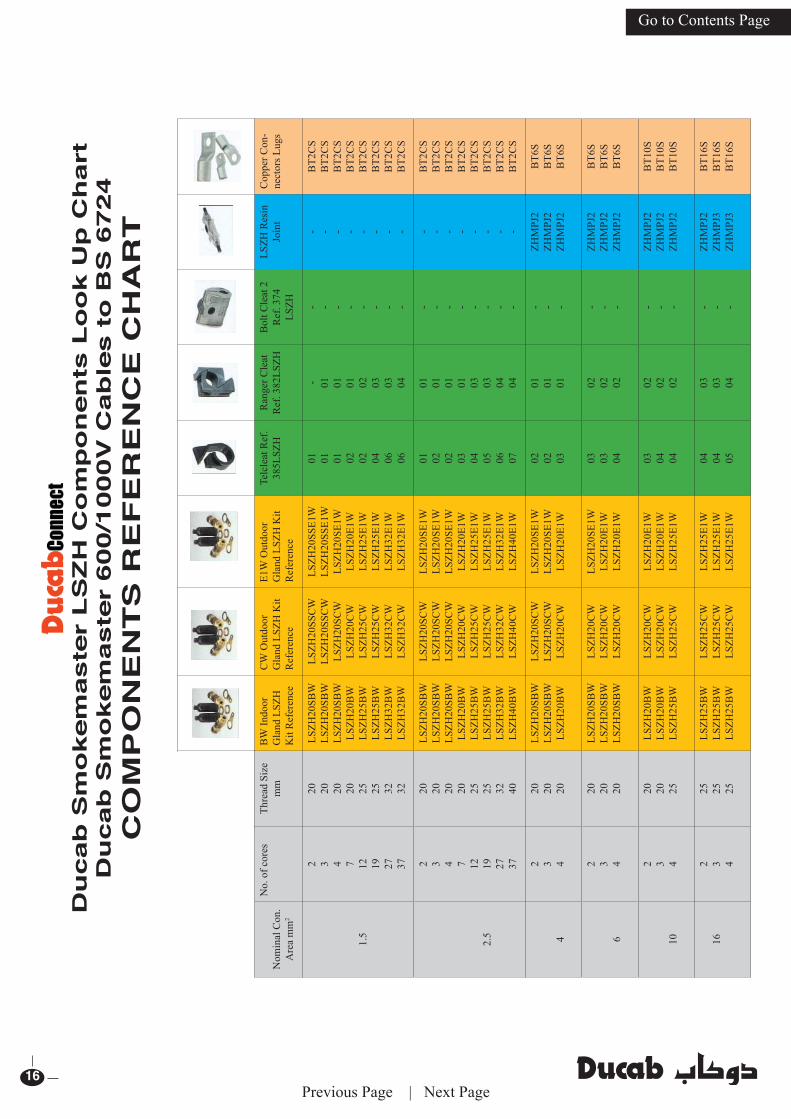
Du
cab
Sm
okem
aste
r L
SZ
H C
om
po
nen
ts L
oo
k U
p C
hart
Du
cab
Sm
okem
aste
r 600/1
000V
Cab
les t
o B
S 6
724
CO
MP
ON
EN
TS
RE
FE
RE
NC
E C
HA
RT
Previous Page | Next Page

... Helping you see more clearly 17
Go to Contents Page
Nom
inal
Con
.A
rea
mm
2N
o. o
f cor
es
Thre
ad S
ize
mm
BW
Indo
or
Gla
nd L
SZH
K
it R
efer
ence
CW
Out
door
G
land
LSZ
HK
it R
efer
ence
E1W
Out
door
G
land
LSZ
H
Kit
Ref
eren
ce
Telc
leat
Ref
. 38
5LSZ
HR
ange
r Cle
atR
ef. 3
82LS
ZH2
Bol
t Cle
atR
ef. 3
74 L
SZH
LSZH
Res
in
Join
tC
oppe
r Con
- - ne
ctor
s Lug
s
252 3 4
25 32 32
LSZH
25B
WLS
ZH32
BW
LSZH
32B
W
LSZH
25C
WLS
ZH32
CW
LSZH
32C
W
LSZH
2E1W
LSZH
32E1
WLS
ZH32
E1W
05 05 06
03 03 04
- - -
ZHM
PJ2
ZHM
PJ3
ZHM
PJ4
BT2
5CS
BT2
5CS
BT2
5CS
352 3 4
32 32 32
LSZH
32B
WLS
ZH32
BW
LSZH
32B
W
LSZH
32C
WLS
ZH32
CW
LSZH
32C
W
LSZH
32E1
WLS
ZH32
E1W
LSZH
32E1
W
06 06 06
04 04 04
- - -
ZHM
PJ3
ZHM
PJ4
ZHM
PJ4
BT3
5CS
BT3
5CS
BT3
5CS
502 3 4
25 32 32
LSZH
25B
WLS
ZH32
BW
LSZH
32B
W
LSZH
25C
WLS
ZH32
CW
LSZH
32C
W
LSZH
25E1
WLS
ZH32
E1W
LSZH
32E1
W
05 06 06
03 04 04
- - -
ZHM
PJ3
ZHM
PJ5
ZHM
PJ5
BT5
0CS
BT5
0CS
BT5
0CS
702 3 4
32 32 40
LSZH
32B
WLS
ZH32
BW
LSZH
40B
W
LSZH
32C
WLS
ZH32
CW
LSZH
40C
W
LSZH
32E1
WLS
ZH32
E1W
LSZH
40E1
W
06 06 07
04 04 05
- - -
ZHM
PJ4
ZHM
PJ5
ZHM
PJ5
BT7
0CS
BT7
0CS
BT7
0CS
952 3 4
32 40 50
LSZH
32B
WLS
ZH40
BW
LSZH
50B
W
LSZH
32C
WLS
ZH40
CW
LSZH
50C
W
LSZH
32E1
WLS
ZH40
E1W
LSZH
50E1
W
06 07 08
04 05 05
- - -
ZHM
PJ4
ZHM
PJ5
ZHM
PJ5
BT9
5CS
BT9
5CS
BT9
5CS
120
2 3 4
40 50 50
LSZH
40B
WLS
ZH50
BW
LSZH
50B
W
LSZH
40C
WLS
ZH50
CW
LSZH
50C
W
LSZH
40E1
WLS
ZH50
E1W
LSZH
50E1
W
07 07 08
04 05 05
- - -
ZHM
PJ5
ZHM
PJ6
ZHM
PJ6
BT1
20C
SB
T120
CS
BT1
20C
S
150
2 3 4
40 50 50
LSZH
40B
WLS
ZH50
BW
LSZH
50B
W
LSZH
40C
WLS
ZH50
CW
LSZH
50C
W
LSZH
40E1
WLS
ZH50
E1W
LSZH
50E1
W
07 08 08
05 05 05
- - -
ZHM
PJ5
ZHM
PJ6
ZHM
PJ6
BT1
50C
SB
T150
CS
BT1
50C
S
185
2 3 4
50 50 63
LSZH
50B
WLS
ZH50
BW
LSZH
63B
W
LSZH
50C
WLS
ZH50
CW
LSZH
63C
W
LSZH
50E1
WLS
ZH50
E1W
LSZH
63E1
W
08 08 -
05 05 06
- - 01
ZHM
PJ5
ZHM
PJ6
ZHM
PJ6
BT1
85C
SB
T185
CS
BT1
85C
S
240
2 3 4
50 63 63
LSZH
50B
WLS
ZH63
BW
LSZH
63B
W
LSZH
50C
WLS
ZH63
CW
LSZH
63C
W
LSZH
50E1
WLS
ZH63
E1W
LSZH
63E1
W
08 - -
05 06 06
- 01 02
ZHM
PJ6
ZHM
PJ7
ZHM
PJ7
BT2
40C
SB
T240
CS
BT2
40C
S
300
2 3 4
50 63 75
LSZH
50B
WLS
ZH63
BW
LSZH
75SB
W
LSZH
50C
WLS
ZH63
CW
LSZH
75C
W
LSZH
50E1
W
LSZH
63E1
WLS
ZH75
E1W
- - -
06 06 06
01 02 03
ZHM
PJ6
ZHM
PJ7
ZHM
PJ7
BT3
00C
SB
T300
CS
BT3
00C
S
400
2 3 4
63 75 75
LSZH
50B
WLS
ZH75
SBW
LSZH
75B
W
LSZH
63C
WLS
ZH75
CW
LSZH
75C
W
LSZH
63E1
WLS
ZH75
E1W
LSZH
75E1
W
- - -
06 06 06
02 03 04
- -ZH
MPJ
8
BT4
00C
SB
T400
CS
BT4
00C
S
All c
ompo
nent
s ava
ilable
from
Duc
ab C
onne
ct an
d aut
horis
ed di
stribu
tors
Plea
se N
ote:
Whe
n or
derin
g con
necto
rs sp
ecify
stud
hole
size
requ
ired,
eg. B
T10C
S8 is
a 10
mm
2 con
necto
r with
a 8 m
m st
ud h
ole.
Impo
rtant
Not
e: Th
e dim
ensio
ns of
cable
s var
y with
man
ufac
turin
g tole
ranc
es. W
e adv
ise th
e cab
le di
amete
r is m
easu
red w
here
possi
ble be
fore
purch
asin
g com
pone
nt.
The r
ecom
men
datio
ns h
ere ar
e give
n in
good
faith
but D
ucab
Con
nect
cann
ot be
held
liab
le fo
r mist
akes
in se
lectio
n ho
weve
r cau
sed.
Previous Page | Next Page

Ducab - Jebel Ali FactoryP.O. Box 11529, Jebel Ali, DubaiTel: +971 4 815 8888, Fax: +971 4 815 8111Email: [email protected]
Ducab Mussafah 1 FactoryP.O. Box 9171, Abu Dhabi, UAETel: +971 2 502 7777, Fax: +971 2 502 7755Email: [email protected]
Ducab Mussafah 2 FactoryP.O. Box 9171, Abu Dhabi, UAETel: +971 2 550 0774, Fax: +971 2 550 0979Email: [email protected]
Ducab Abu Dhabi Sales Of ce (ADSO)P.O. Box 9171, Abu Dhabi, UAETel: +971 2 502 7777, Fax: +971 2 502 7890Email: [email protected]
Ducab - OmanP.O. Box 3542,112 RUWI, Muscat, OmanTel: +968 245 651 78, Fax: +968 245 643 02Email: [email protected]
DUCAB - UKSuite 17, Leatherline House Business Centre71 Narrow Lane, Aylestone,Leicester.LE2 8NA, United KingdomTel: +44 07919 095500, Fax: +44 07901 651202Email: [email protected]
Ducab Joint Venture – BahrainBICC MET W.L.L, P.O. Box 11413, Manama, Kingdom of BahrainTel: +973 177 497 61, Fax: +973 177 280 27Email: [email protected]
Ducab Joint Venture - QatarJBK DUCAB W.L.L (JV)P.O. Box 14039, Doha, QatarTel: +974 4442 1924Fax: +974 4441 9003Email: [email protected]
Dubai Cable Co (P) Ltd. (DUCAB) - KSA403, Al-Za’abi Tower,Prince Mohammad Bin Fahad Road, 1st StreetP.O. Box: 60662, Dammam-31555, KSA Tel: +966 3 835 5305, Fax: +966 3 835 5307 Mobile: +966 50 825 5581 Email: [email protected]
Ducab - QatarP.O. Box 23209, Doha, QatarTel: +974 4016 4070, Fax: +974 4016 4072Mobile: +974 3351 6218Email: [email protected]