Embed Size (px)
Citation preview

1600SvcMan REV: 12/13/05
SERVICE MANUAL(DOMESTIC & INTERNATIONAL)
IMPINGER CONVEYOR OVENS
LOW PROFILE - 1600 SERIES
Lincoln Foodservice Products, Inc.1111 North Hadley Road
P.O. Box 1229Fort Wayne, Indiana 46801-1229
Phone: (800) 374-3004 • Fax: (260) 436-0735
Technical Service Hot Line(800) 678-9511
www.lincolnfp.com
Low Profile -–1600 Series Service Manual – Dom & Int’l2
TABLE OF CONTENTSTABLE OF CONTENTS..............................................................................................................................................2SEQUENCE OF OPERATIONS 1600 / 1601 / 1652..................................................................................................3SEQUENCE OF OPERATIONS 1622 / 1623.............................................................................................................4SEQUENCE OF OPERATIONS / 1628 / 1629...........................................................................................................5SEQUENCE OF OPERATIONS / 1646, 1647, 1650, 1651........................................................................................7SCHEMATIC / 1600, 1601, 1652 ...............................................................................................................................9SCHEMATIC / 1622, 1623........................................................................................................................................10SCHEMATIC / 1628, 1629........................................................................................................................................11SCHEMATIC / 1646, 1647, 1650, 1651 ...................................................................................................................12TROUBLESHOOTING GAS OVENS ......................................................................................................................13TROUBLESHOOTING / 1622, 1623, 1628, 1629 ...................................................................................................20TROUBLESHOOTING / 1646, 1647, 1650, 1651 ....................................................................................................26REMOVAL, INSTALLATION & ADJUSTMENTS .....................................................................................................32PARTS / GENERAL - 1600 SERIES........................................................................................................................48BLOW UP / GENERAL – 1600 SERIES...................................................................................................................49PARTS / CONTROL BOX, RIGHT- 1600 - 1601 - 1652 ..........................................................................................50BLOW UP / CONTROL BOX RIGHT – 1600, 1601, 1652 .......................................................................................51PARTS / CONTROL BOX, LEFT - 1600 - 1601 - 1652............................................................................................52BLOW UP / CONTROL BOX LEFT – 1600, 1601, 1652..........................................................................................53PARTS / CONTROL BOX, RIGHT –1622,1623,1628,1629.....................................................................................54BLOW UP / CONTROL BOX RIGHT – 1622,1623,1628,1629 ................................................................................55PARTS / CONTROL BOX, LEFT 1622,1623,1628,1629 .........................................................................................56BLOW UP / CONTROL BOX LEFT – 1622, 1623, 1628, 1629................................................................................57PARTS / CONTROL BOX RIGHT – 1646, 1647, 1650, 1651..................................................................................58BLOW UP / CONTROL BOX RIGHT – 1646,1647,1650,1651 ................................................................................59PARTS / CONTROL BOX LEFT – 1646, 1647, 1650, 1651 ....................................................................................60BLOW UP / CONTROL BOX LEFT – 1646,1647,1650,1651...................................................................................61PARTS / BACK - 1600 SERIES ...............................................................................................................................62BLOW UP / BACK – 1600 SERIES..........................................................................................................................63PARTS / CONVEYOR - 1600 SERIES.....................................................................................................................64BLOW UP / CONVEYOR – 1600 SERIES ...............................................................................................................65
Low Profile -–1600 Series Service Manual – Dom & Int’l 3
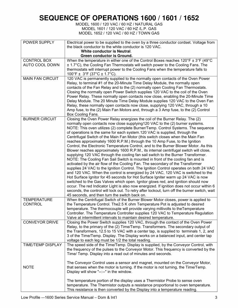
SEQUENCE OF OPERATIONS 1600 / 1601 / 1652MODEL 1600 / 120 VAC / 60 HZ / NATURAL GAS
MODEL 1601 / 120 VAC / 60 HZ /L.P. GASMODEL 1652 / 120 VAC / 60 HZ / TOWN GAS
POWER SUPPLY Electrical power to be supplied to the oven by a three conductor cordset. Voltage fromthe black conductor to the white conductor is 120 VAC.
White conductor is Neutral.Green conductor is Ground.
CONTROL BOXAUTO COOL DOWN
When the temperature in either one of the Control Boxes reaches 120°F ± 3°F (49°C± 1.7°C), the Cooling Fan Thermostats will switch power to the Cooling Fans. Thethermostats will interrupt power to the Cooling Fans when the temperature falls to100°F ± 3°F (37°C ± 1.7°C).
MAIN FAN CIRCUIT 120 VAC is permanently supplied to the normally open contacts of the Oven PowerRelay, to terminal #1 of the 20-Minute Time Delay Module, the normally opencontacts of the Fan Relay and to the (2) normally open Cooling Fan Thermostats.Closing the normally open Power Switch supplies 120 VAC to the coil of the OvenPower Relay. These normally open contacts now close, enabling the 20-Minute TimeDelay Module. The 20 Minute Time Delay Module supplies 120 VAC to the Oven FanRelay, these normally open contacts now close, supplying 120 VAC, through a 10Amp fuse, to the (2) Main Fan Motors and, through a 3 Amp fuse, to the (2) ControlBox Cooling Fans.
BURNER CIRCUIT Closing the Oven Power Relay energizes the coil of the Burner Relay. The (2)normally open contacts now close supplying120 VAC to the (2) burner systems.NOTE: This oven utilizes (2) complete Burner/Temp. Control Systems. The sequenceof operations is the same for each system.120 VAC is supplied, through theCentrifugal Switch of the Main Fan Motor (this switch closes when the Main Fanreaches approximately 1600 R.P.M.) through the 10 Amp Fuse, to the IgnitionControl, the Electronic Temperature Control, and to the Burner Blower Motor. As thisBlower reaches approximately 1600 R.P.M., its internal centrifugal switch will close,supplying 120 VAC through the cooling fan sail switch to the Burner Transformer.NOTE: The Cooling Fan Sail Switch is mounted in front of the cooling fan and isactivated by the air flow of the Cooling Fan. The secondary of the Transformersupplies 24 VAC to the Ignition Control. The Ignition Control operates on both 24 VACand 120 VAC. When the control is energized by 24 VAC, 120 VAC is switched to theHot Surface Ignitor for 45 seconds for Hot Surface Igniter warm up 24 VAC is nowswitched to the Gas Valves which open. Ignitor glows red, and ignition should nowoccur. The red Indicator Light is also now energized. If ignition does not occur within 6seconds, the control will lock out. To retry after lockout, turn off the burner switch, wait45 seconds, and then turn the switch back on.
TEMPERATURECONTROL
When the Centrifugal Switch of the Burner Blower Motor closes, power is applied tothe Temperature Control. The2.5 K ohm Temperature Pot is adjusted to desiredtemperature. The thermocouple will provide varying millivolts to theTemperatureController. The Temperature Controller supplies 120 VAC to Temperature RegulationValve at intermittent intervals to maintain desired temperature.
CONVEYOR DRIVE Closing the Power Switch supplies 120 VAC, through the contact of the Oven PowerRelay, to the primary of the (2) Time/Temp. Transformers. The secondary output ofthe Transformers, 12.5 to 15 VAC with a center tap, is supplied to terminals 1, 2, and3 of the Time/Temp. Display. The Display works on a balanced input, and center tapvoltage to each leg must be 1/2 the total reading.
TIME/TEMP DISPLAY
NOTE
The speed side of the Time/Temp. Display is supplied, by the Conveyor Control, withthe frequency of the pulses to the Conveyor Motor. This frequency is converted by theTime/ Temp. Display into a read out of minutes and seconds.
The Conveyor Control uses a sensor and magnet, mounted on the Conveyor Motor,that senses when the motor is turning. If the motor is not turning, the Time/Temp.Display will show "--:--" in the window.
The temperature portion of the display uses a Thermistor Probe to sense oventemperature. The Thermistor outputs a resistance proportional to oven temperature.This resistance is then converted by the Display into a temperature reading.
Low Profile -–1600 Series Service Manual – Dom & Int’l4
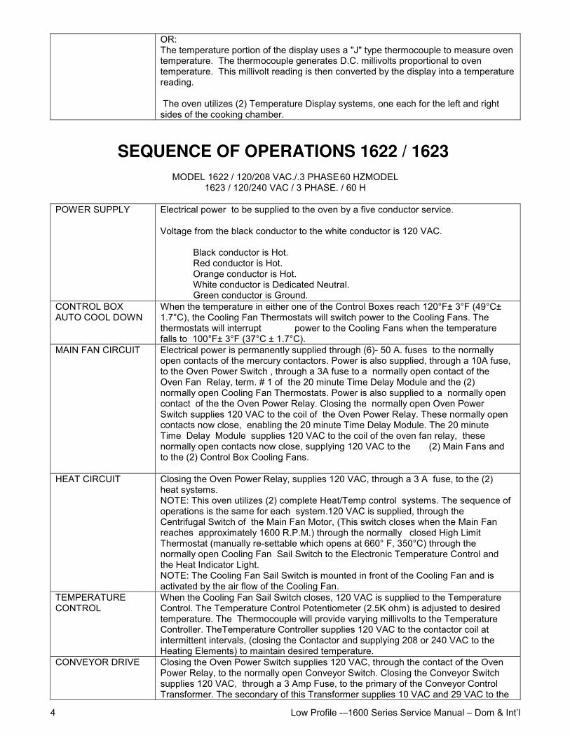
OR:The temperature portion of the display uses a "J" type thermocouple to measure oventemperature. The thermocouple generates D.C. millivolts proportional to oventemperature. This millivolt reading is then converted by the display into a temperaturereading.
The oven utilizes (2) Temperature Display systems, one each for the left and rightsides of the cooking chamber.
SEQUENCE OF OPERATIONS 1622 / 1623MODEL 1622 / 120/208 VAC./.3 PHASE60 HZMODEL
1623 / 120/240 VAC / 3 PHASE. / 60 H
POWER SUPPLY Electrical power to be supplied to the oven by a five conductor service.
Voltage from the black conductor to the white conductor is 120 VAC.
Black conductor is Hot.Red conductor is Hot.Orange conductor is Hot.White conductor is Dedicated Neutral.Green conductor is Ground.
CONTROL BOXAUTO COOL DOWN
When the temperature in either one of the Control Boxes reach 120°F± 3°F (49°C±1.7°C), the Cooling Fan Thermostats will switch power to the Cooling Fans. Thethermostats will interrupt power to the Cooling Fans when the temperaturefalls to 100°F± 3°F (37°C ± 1.7°C).
MAIN FAN CIRCUIT Electrical power is permanently supplied through (6)- 50 A. fuses to the normallyopen contacts of the mercury contactors. Power is also supplied, through a 10A fuse,to the Oven Power Switch , through a 3A fuse to a normally open contact of theOven Fan Relay, term. # 1 of the 20 minute Time Delay Module and the (2)normally open Cooling Fan Thermostats. Power is also supplied to a normally opencontact of the the Oven Power Relay. Closing the normally open Oven PowerSwitch supplies 120 VAC to the coil of the Oven Power Relay. These normally opencontacts now close, enabling the 20 minute Time Delay Module. The 20 minuteTime Delay Module supplies 120 VAC to the coil of the oven fan relay, thesenormally open contacts now close, supplying 120 VAC to the (2) Main Fans andto the (2) Control Box Cooling Fans.
HEAT CIRCUIT Closing the Oven Power Relay, supplies 120 VAC, through a 3 A fuse, to the (2)heat systems.NOTE: This oven utilizes (2) complete Heat/Temp control systems. The sequence ofoperations is the same for each system.120 VAC is supplied, through theCentrifugal Switch of the Main Fan Motor, (This switch closes when the Main Fanreaches approximately 1600 R.P.M.) through the normally closed High LimitThermostat (manually re-settable which opens at 660° F, 350°C) through thenormally open Cooling Fan Sail Switch to the Electronic Temperature Control andthe Heat Indicator Light.NOTE: The Cooling Fan Sail Switch is mounted in front of the Cooling Fan and isactivated by the air flow of the Cooling Fan.
TEMPERATURECONTROL
When the Cooling Fan Sail Switch closes, 120 VAC is supplied to the TemperatureControl. The Temperature Control Potentiometer (2.5K ohm) is adjusted to desiredtemperature. The Thermocouple will provide varying millivolts to the TemperatureController. TheTemperature Controller supplies 120 VAC to the contactor coil atintermittent intervals, (closing the Contactor and supplying 208 or 240 VAC to theHeating Elements) to maintain desired temperature.
CONVEYOR DRIVE Closing the Oven Power Switch supplies 120 VAC, through the contact of the OvenPower Relay, to the normally open Conveyor Switch. Closing the Conveyor Switchsupplies 120 VAC, through a 3 Amp Fuse, to the primary of the Conveyor ControlTransformer. The secondary of this Transformer supplies 10 VAC and 29 VAC to the
Low Profile -–1600 Series Service Manual – Dom & Int’l 5
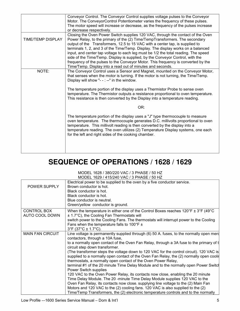
Conveyor Control. The Conveyor Control supplies voltage pulses to the ConveyorMotor. The ConveyorControl Potentiometer varies the frequency of these pulses.The motor speed will increase or decrease, as the frequency of the pulses increaseor decrease respectively.
TIME/TEMP DISPLAYClosing the Oven Power Switch supplies 120 VAC, through the contact of the OvenPower Relay, to the primary of the (2) Time/TempTransformers. The secondaryoutput of the Transformers, 12.5 to 15 VAC with a center tap, is supplied toterminals 1, 2, and 3 of the Time/Temp. Display. The display works on a balancedinput, and center tap voltage to each leg must be 1/2 the total reading. The speedside of the Time/Temp. Display is supplied, by the Conveyor Control, with thefrequency of the pulses to the Conveyor Motor. This frequency is converted by theTime/Temp. Display into a read out of minutes and seconds.
NOTE: The Conveyor Control uses a Sensor and Magnet, mounted on the Conveyor Motor,that senses when the motor is turning. If the motor is not turning, the Time/Temp.Display will show "- - : --" in the window.
The temperature portion of the display uses a Thermistor Probe to sense oventemperature. The Thermistor outputs a resistance proportional to oven temperature.This resistance is then converted by the Display into a temperature reading.
OR:
The temperature portion of the display uses a "J" type thermocouple to measureoven temperature. The thermocouple generates D.C. millivolts proportional to oventemperature. This millivolt reading is then converted by the display into atemperature reading. The oven utilizes (2) Temperature Display systems, one eachfor the left and right sides of the cooking chamber.
SEQUENCE OF OPERATIONS / 1628 / 1629MODEL 1628 / 380/220 VAC / 3 PHASE / 50 HZMODEL 1629 / 415/240 VAC / 3 PHASE / 50 HZ
POWER SUPPLYElectrical power to be supplied to the oven by a five conductor service.Brown conductor is hot.Black conductor is hot.Black conductor is hot.Blue conductor is neutral.Green/yellow conductor is ground.
CONTROL BOXAUTO COOL DOWN
When the temperature in either one of the Control Boxes reaches 120°F ± 3°F (49°C± 1.7°C), the Cooling Fan Thermostats willswitch power to the Cooling Fans. The thermostats will interrupt power to the CoolingFans when the temperature falls to 100°F ±3°F (37°C ± 1.7°C).
MAIN FAN CIRCUIT Line voltage is permanently supplied through (6) 50 A. fuses, to the normally open mercurycontactors, through a 10A fuse,to a normally open contact of the Oven Fan Relay, through a 3A fuse to the primary of the controlcircuit step down transformer.(The transformer steps the voltage down to 120 VAC for the control circuit). 120 VAC is permanentlysupplied to a normally open contact of the Oven Fan Relay, the (2) normally open cooling fanthermostats, a normally open contact of the Oven Power Relay,terminal #1 of the 20 minute Time Delay Module and to the normally open Power Switch. Closing thePower Switch supplies120 VAC to the Oven Power Relay, its contacts now close, enabling the 20 minuteTime Delay Module. The 20 -minute Time Delay Module supplies 120 VAC to theOven Fan Relay, its contacts now close. supplying line voltage to the (2) Main FanMotors and 120 VAC to the (2) cooling fans. 120 VAC is also supplied to the (2)Time/Temp Transformers, the (2) electronic temperature controls and to the normally
Low Profile -–1600 Series Service Manual – Dom & Int’l6
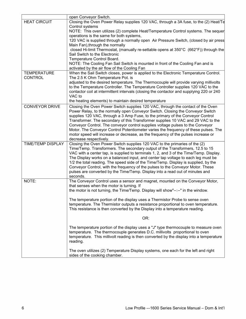
open Conveyor Switch.HEAT CIRCUIT Closing the Oven Power Relay supplies 120 VAC, through a 3A fuse, to the (2) Heat/Temperature
Control systemsNOTE: This oven utilizes (2) complete Heat/Temperature Control systems. The sequence ofoperations is the same for both systems,120 VAC is supplied through a normally open Air Pressure Switch, (closed by air pressure from theMain Fan),through the normally closed Hi-limit Thermostat, (manually re-settable opens at 350°C (662°F)) through the Cooling FanSail Switch to the ElectronicTemperature Control Board.NOTE: The Cooling Fan Sail Switch is mounted in front of the Cooling Fan and isactivated by the air flow of the Cooling Fan
TEMPERATURECONTROL
When the Sail Switch closes, power is applied to the Electronic Temperature Control.The 2.5 K Ohm Temperature Pot. isadjusted to the desired temperature. The Thermocouple will provide varying millivoltsto the Temperature Controller. The Temperature Controller supplies 120 VAC to thecontactor coil at intermittent intervals (closing the contactor and supplying 220 or 240VAC tothe heating elements) to maintain desired temperature
CONVEYOR DRIVE Closing the Oven Power Switch supplies 120 VAC, through the contact of the OvenPower Relay, to the normally open Conveyor Switch. Closing the Conveyor Switchsupplies 120 VAC, through a 3 Amp Fuse, to the primary of the Conveyor ControlTransformer. The secondary of this Transformer supplies 10 VAC and 29 VAC to theConveyor Control. The conveyor control supplies voltage pulses to the ConveyorMotor. The Conveyor Control Potentiometer varies the frequency of these pulses. Themotor speed will increase or decrease, as the frequency of the pulses increase ordecrease respectively.
TIME/TEMP DISPLAY Closing the Oven Power Switch supplies 120 VAC to the primaries of the (2)Time/Temp. Transformers. The secondary output of the Transformers, 12.5 to 15VAC with a center tap, is supplied to terminals 1, 2, and 3 of the Time/Temp. Display.The Display works on a balanced input, and center tap voltage to each leg must be1/2 the total reading. The speed side of the Time/Temp. Display is supplied, by theConveyor Control, with the frequency of the pulses to the Conveyor Motor. Thesepulses are converted by the Time/Temp. Display into a read out of minutes andseconds.
NOTE: The Conveyor Control uses a sensor and magnet, mounted on the Conveyor Motor,that senses when the motor is turning. Ifthe motor is not turning, the Time/Temp. Display will show"--:--" in the window.
The temperature portion of the display uses a Thermistor Probe to sense oventemperature. The Thermistor outputs a resistance proportional to oven temperature.This resistance is then converted by the Display into a temperature reading.
OR:
The temperature portion of the display uses a "J" type thermocouple to measure oventemperature. The thermocouple generates D.C. millivolts proportional to oventemperature. This millivolt reading is then converted by the display into a temperaturereading.
The oven utilizes (2) Temperature Display systems, one each for the left and rightsides of the cooking chamber.
Low Profile -–1600 Series Service Manual – Dom & Int’l 7
SEQUENCE OF OPERATIONS / 1646, 1647, 1650, 1651MODEL 1646 / 220-240 VAC / 50 HZ / NATURAL GAS
MODEL 1647 / 220-240 VAC / 50 HZ / L.P. GASMODEL 1650 / 220-240 VAC / 50 HZ / TOWN GASMODEL 1651 / 220-240 VAC / 50 HZ / TOWN GAS
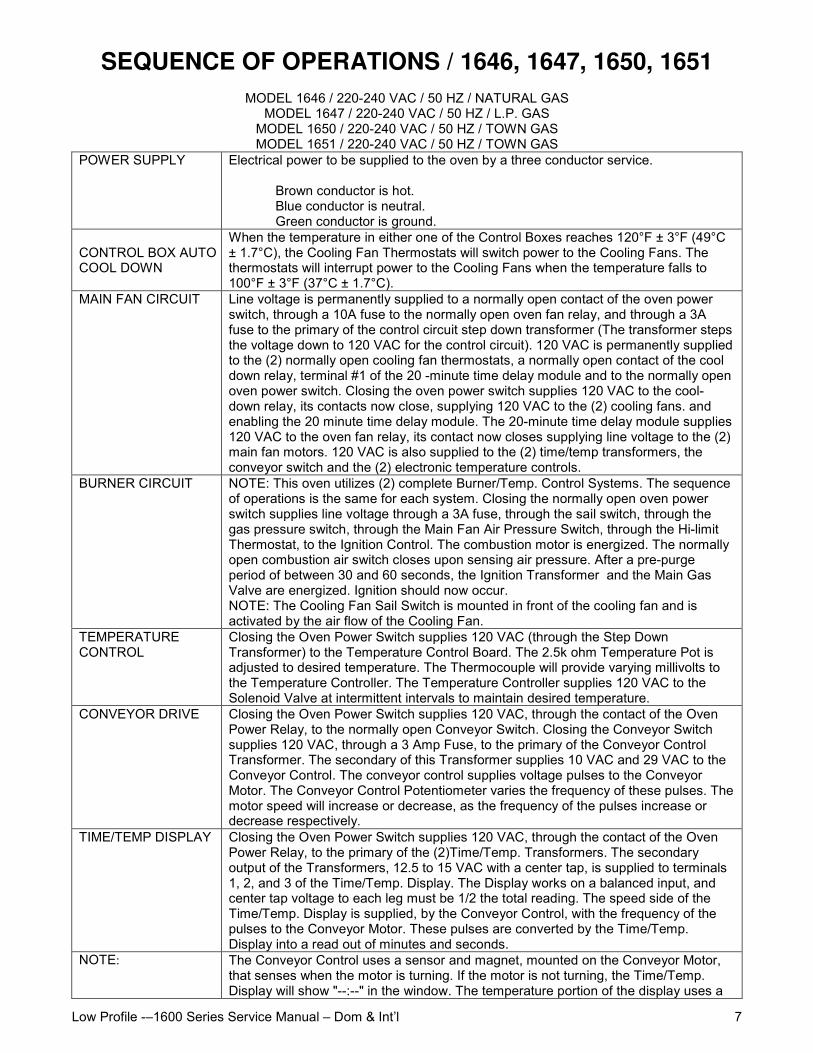
POWER SUPPLY Electrical power to be supplied to the oven by a three conductor service.
Brown conductor is hot.Blue conductor is neutral.Green conductor is ground.
CONTROL BOX AUTO COOL AUTOCOOL DOWN
When the temperature in either one of the Control Boxes reaches 120°F ± 3°F (49°C± 1.7°C), the Cooling Fan Thermostats will switch power to the Cooling Fans. Thethermostats will interrupt power to the Cooling Fans when the temperature falls to100°F ± 3°F (37°C ± 1.7°C).
MAIN FAN CIRCUIT Line voltage is permanently supplied to a normally open contact of the oven powerswitch, through a 10A fuse to the normally open oven fan relay, and through a 3Afuse to the primary of the control circuit step down transformer (The transformer stepsthe voltage down to 120 VAC for the control circuit). 120 VAC is permanently suppliedto the (2) normally open cooling fan thermostats, a normally open contact of the cooldown relay, terminal #1 of the 20 -minute time delay module and to the normally openoven power switch. Closing the oven power switch supplies 120 VAC to the cool-down relay, its contacts now close, supplying 120 VAC to the (2) cooling fans. andenabling the 20 minute time delay module. The 20-minute time delay module supplies120 VAC to the oven fan relay, its contact now closes supplying line voltage to the (2)main fan motors. 120 VAC is also supplied to the (2) time/temp transformers, theconveyor switch and the (2) electronic temperature controls.
BURNER CIRCUIT NOTE: This oven utilizes (2) complete Burner/Temp. Control Systems. The sequenceof operations is the same for each system. Closing the normally open oven powerswitch supplies line voltage through a 3A fuse, through the sail switch, through thegas pressure switch, through the Main Fan Air Pressure Switch, through the Hi-limitThermostat, to the Ignition Control. The combustion motor is energized. The normallyopen combustion air switch closes upon sensing air pressure. After a pre-purgeperiod of between 30 and 60 seconds, the Ignition Transformer and the Main GasValve are energized. Ignition should now occur.NOTE: The Cooling Fan Sail Switch is mounted in front of the cooling fan and isactivated by the air flow of the Cooling Fan.
TEMPERATURECONTROL
Closing the Oven Power Switch supplies 120 VAC (through the Step DownTransformer) to the Temperature Control Board. The 2.5k ohm Temperature Pot isadjusted to desired temperature. The Thermocouple will provide varying millivolts tothe Temperature Controller. The Temperature Controller supplies 120 VAC to theSolenoid Valve at intermittent intervals to maintain desired temperature.
CONVEYOR DRIVE Closing the Oven Power Switch supplies 120 VAC, through the contact of the OvenPower Relay, to the normally open Conveyor Switch. Closing the Conveyor Switchsupplies 120 VAC, through a 3 Amp Fuse, to the primary of the Conveyor ControlTransformer. The secondary of this Transformer supplies 10 VAC and 29 VAC to theConveyor Control. The conveyor control supplies voltage pulses to the ConveyorMotor. The Conveyor Control Potentiometer varies the frequency of these pulses. Themotor speed will increase or decrease, as the frequency of the pulses increase ordecrease respectively.
TIME/TEMP DISPLAY Closing the Oven Power Switch supplies 120 VAC, through the contact of the OvenPower Relay, to the primary of the (2)Time/Temp. Transformers. The secondaryoutput of the Transformers, 12.5 to 15 VAC with a center tap, is supplied to terminals1, 2, and 3 of the Time/Temp. Display. The Display works on a balanced input, andcenter tap voltage to each leg must be 1/2 the total reading. The speed side of theTime/Temp. Display is supplied, by the Conveyor Control, with the frequency of thepulses to the Conveyor Motor. These pulses are converted by the Time/Temp.Display into a read out of minutes and seconds.
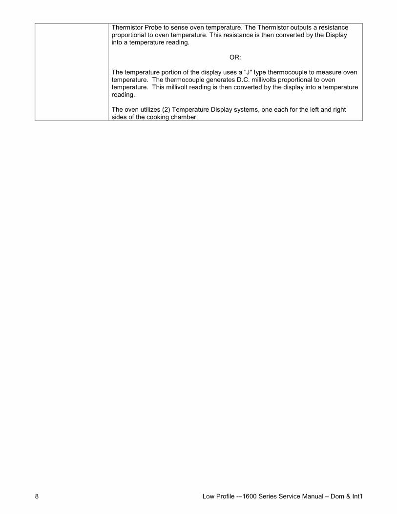
NOTE: The Conveyor Control uses a sensor and magnet, mounted on the Conveyor Motor,that senses when the motor is turning. If the motor is not turning, the Time/Temp.Display will show "--:--" in the window. The temperature portion of the display uses a
Low Profile -–1600 Series Service Manual – Dom & Int’l8
Thermistor Probe to sense oven temperature. The Thermistor outputs a resistanceproportional to oven temperature. This resistance is then converted by the Displayinto a temperature reading.
OR:
The temperature portion of the display uses a "J" type thermocouple to measure oventemperature. The thermocouple generates D.C. millivolts proportional to oventemperature. This millivolt reading is then converted by the display into a temperaturereading.
The oven utilizes (2) Temperature Display systems, one each for the left and rightsides of the cooking chamber.
Low Profile -–1600 Series Service Manual – Dom & Int’l 9
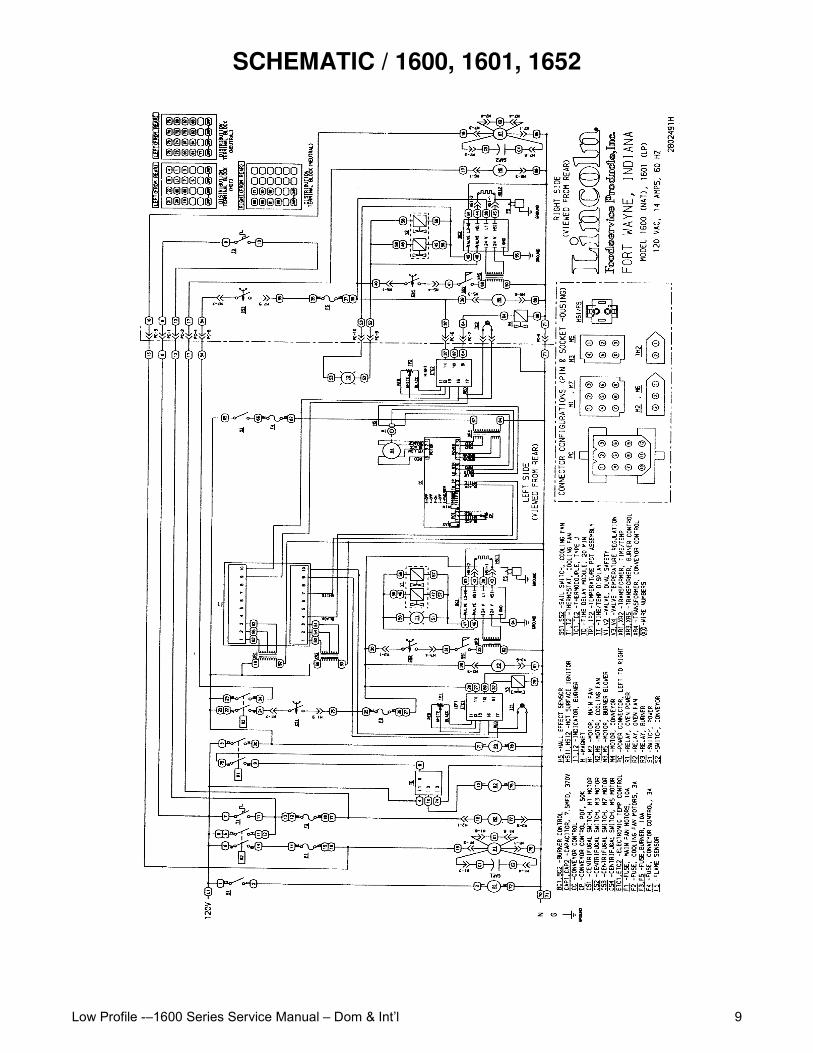
SCHEMATIC / 1600, 1601, 1652
Low Profile -–1600 Series Service Manual – Dom & Int’l10
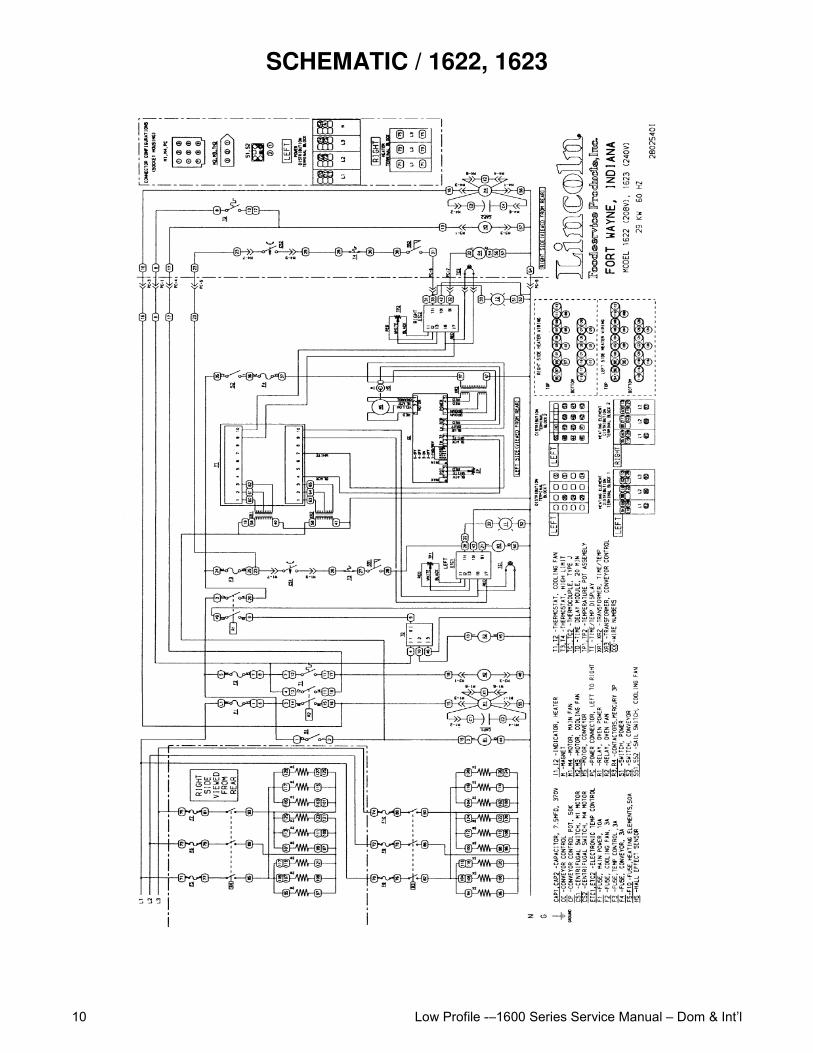
SCHEMATIC / 1622, 1623
Low Profile -–1600 Series Service Manual – Dom & Int’l 11
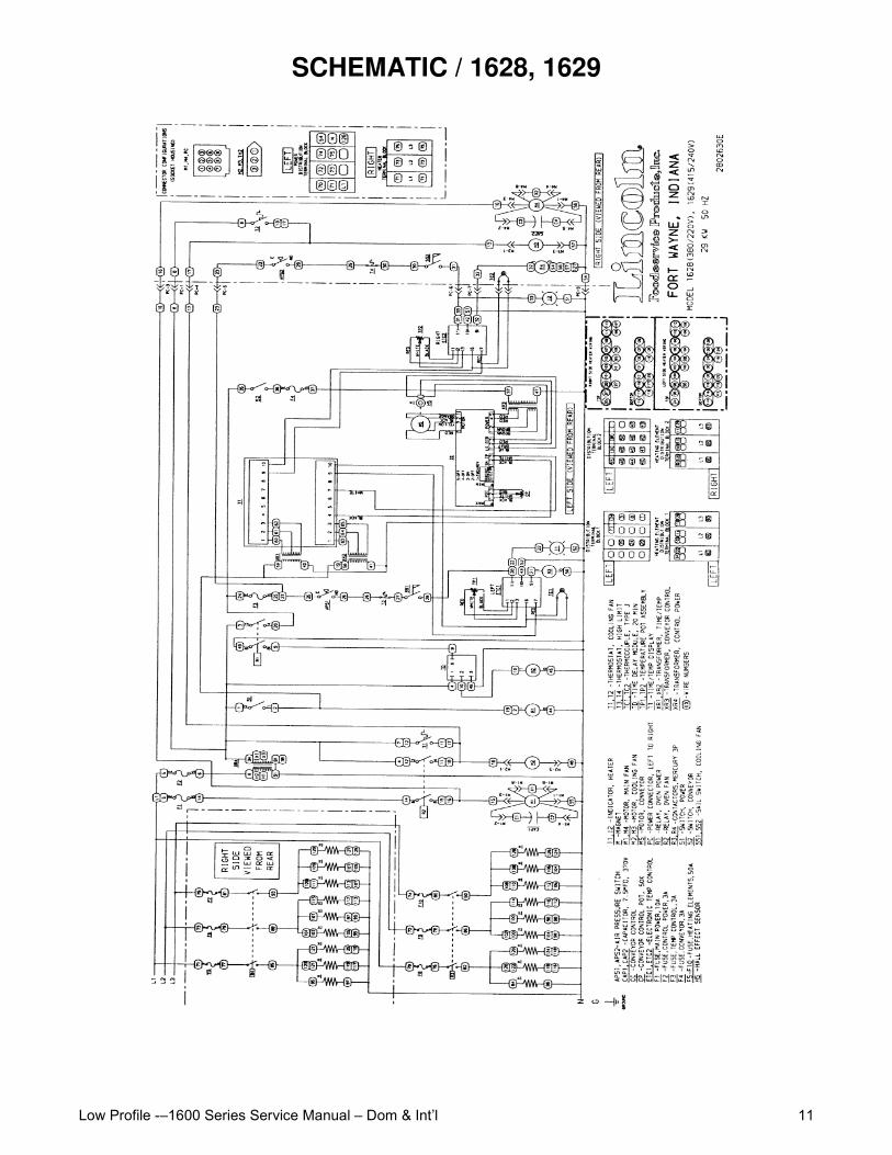
SCHEMATIC / 1628, 1629
Low Profile -–1600 Series Service Manual – Dom & Int’l12
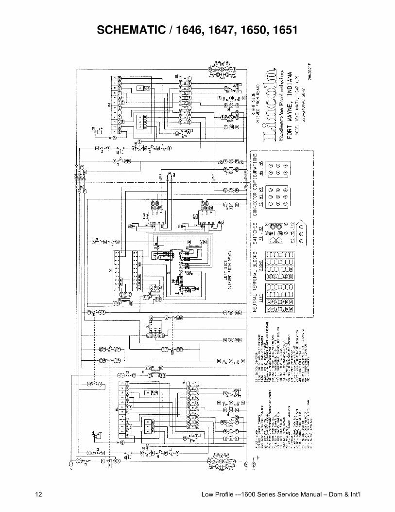
SCHEMATIC / 1646, 1647, 1650, 1651
Low Profile -–1600 Series Service Manual – Dom & Int’l 13
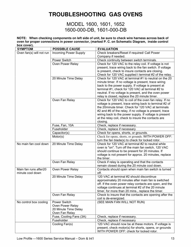
TROUBLESHOOTING GAS OVENS
MODEL 1600, 1601, 16521600-000-DB, 1601-000-DB
NOTE: When checking components on left side of unit, be sure to check wire harness across back ofoven for proper connections in power connector, (marked P. C. on Schematic Diagram, inside controlbox cover).SYMPTOM POSSIBLE CAUSE EVALUATION
Incoming Power Supply Check breakers/Reset if required/ Call PowerCompany if needed.
Power Switch Check continuity between switch terminals.Oven Power Relay Check for 120 VAC to the relay coil. If voltage is not
present, trace wiring back to the fan switch. If voltageis present, check to insure contacts are closing.Check for 120 VAC supplied t terminal #2 of the relay.
20 Minute Time Delay Check for 120 VAC at terminal #1 to neutral on the 20minute timer. If no voltage is present, trace wiringback to the power supply. If voltage is present atterminal #1, check for 120 VAC at terminal #2 toneutral. If no voltage is present, and the oven powerrelay is closed, replace the 20 minute timer.
Oven Fan Relay Check for 120 VAC to coil of the oven fan relay. If novoltage is present, trace wiring back to terminal #2 ofthe 20minute timer. Check for 120 VAC at terminals#2 and #6 of the relay, if no voltage is present, tracewiring back to the power supply. If voltage is presentat the relay coil, check to insure the contacts areclosing.
Fuse, Fan, 10A Check, replace if necessary.Fuseholder Check, replace if necessaryCapacitor(s) Check for opens, shorts, or grounds.
Oven fan(s) will not run
Motor(s) Check for opens, shorts, or grounds. WITH POWER OFF:turn the fan blade(s) to check for locked rotor.
20 Minute Time Delay Check for 120 VAC at terminal #2 to neutral whileoven is "on". Turn off the main fan switch, 120 VACshould continue to be present for 20 minutes. Ifvoltage is not present for approx. 20 minutes, replacethe timer.
No main fan cool down
Oven Fan Relay Check if relay is operating and that the contactsremain closed during the 20 minute cool down.
Oven Power Relay Contacts should open when main fan switch is turnedoff.
20 Minute Time Delay 120 VAC at terminal #2 should discontinueapproximately 20 minutes after main fan is switchedoff. If the oven power relay contacts are open, and thevoltage continues at terminal #2 of the 20 minutetimer, for more than 20 mins., replace the timer.
Main fan runs after20minute cool down
Oven Fan Relay Check to insure that the contacts are opening after thecoil is de-energized.
Power SwitchOven Power Relay20 Minute Time DelayOven Fan Relay
(SEE MAIN FAN WILL NOT RUN)
Fuse, Cooling Fans (3A) Check, replace if necessary.
No control box cooling
Fuseholder Check, replace if necessaryCooling Fan(s) 120 VAC should now be at these motors. If voltage is
present, check motor(s) for shorts, opens, or groundsWITH POWER OFF: check for locked rotor.
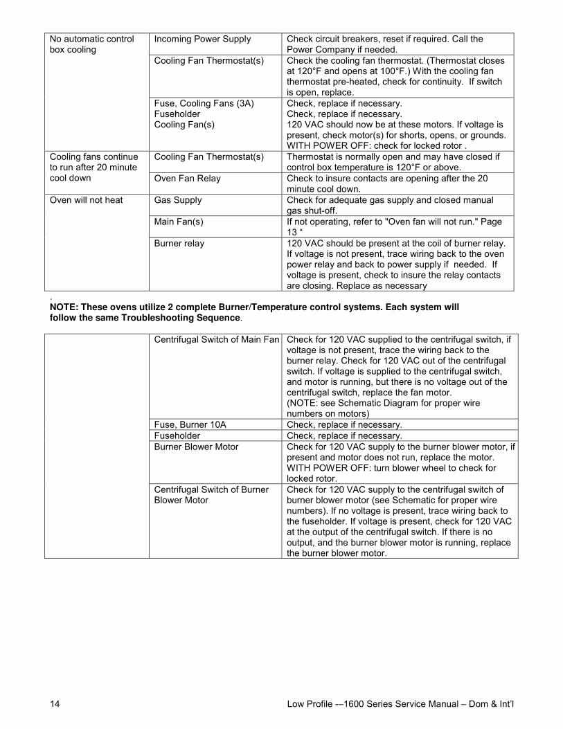
Low Profile -–1600 Series Service Manual – Dom & Int’l14
Incoming Power Supply Check circuit breakers, reset if required. Call thePower Company if needed.
Cooling Fan Thermostat(s) Check the cooling fan thermostat. (Thermostat closesat 120°F and opens at 100°F.) With the cooling fanthermostat pre-heated, check for continuity. If switchis open, replace.
No automatic controlbox cooling
Fuse, Cooling Fans (3A)FuseholderCooling Fan(s)
Check, replace if necessary.Check, replace if necessary.120 VAC should now be at these motors. If voltage ispresent, check motor(s) for shorts, opens, or grounds.WITH POWER OFF: check for locked rotor .
Cooling Fan Thermostat(s) Thermostat is normally open and may have closed ifcontrol box temperature is 120°F or above.
Cooling fans continueto run after 20 minutecool down Oven Fan Relay Check to insure contacts are opening after the 20
minute cool down.Gas Supply Check for adequate gas supply and closed manual
gas shut-off.Main Fan(s) If not operating, refer to "Oven fan will not run." Page
13 “
Oven will not heat
Burner relay 120 VAC should be present at the coil of burner relay.If voltage is not present, trace wiring back to the ovenpower relay and back to power supply if needed. Ifvoltage is present, check to insure the relay contactsare closing. Replace as necessary
.NOTE: These ovens utilize 2 complete Burner/Temperature control systems. Each system willfollow the same Troubleshooting Sequence.
Centrifugal Switch of Main Fan MotorCheck for 120 VAC supplied to the centrifugal switch, ifvoltage is not present, trace the wiring back to theburner relay. Check for 120 VAC out of the centrifugalswitch. If voltage is supplied to the centrifugal switch,and motor is running, but there is no voltage out of thecentrifugal switch, replace the fan motor.(NOTE: see Schematic Diagram for proper wirenumbers on motors)
Fuse, Burner 10A Check, replace if necessary.Fuseholder Check, replace if necessary.Burner Blower Motor Check for 120 VAC supply to the burner blower motor, if 120 VAC is
present and motor does not run, replace the motor.WITH POWER OFF: turn blower wheel to check forlocked rotor.
Centrifugal Switch of BurnerBlower Motor
Check for 120 VAC supply to the centrifugal switch ofburner blower motor (see Schematic for proper wirenumbers). If no voltage is present, trace wiring back tothe fuseholder. If voltage is present, check for 120 VACat the output of the centrifugal switch. If there is nooutput, and the burner blower motor is running, replacethe burner blower motor.
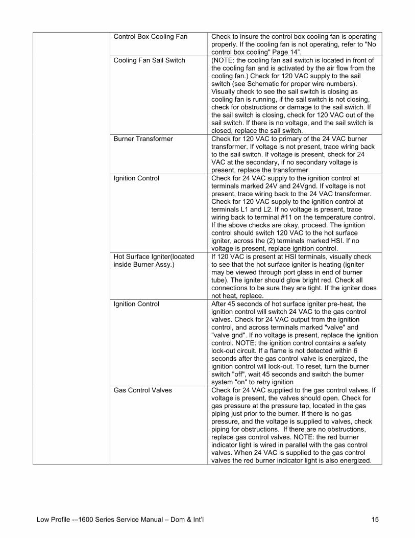
Low Profile -–1600 Series Service Manual – Dom & Int’l 15
Control Box Cooling Fan Check to insure the control box cooling fan is operatingproperly. If the cooling fan is not operating, refer to "Nocontrol box cooling" Page 14”.
Cooling Fan Sail Switch (NOTE: the cooling fan sail switch is located in front ofthe cooling fan and is activated by the air flow from thecooling fan.) Check for 120 VAC supply to the sailswitch (see Schematic for proper wire numbers).Visually check to see the sail switch is closing ascooling fan is running, if the sail switch is not closing,check for obstructions or damage to the sail switch. Ifthe sail switch is closing, check for 120 VAC out of thesail switch. If there is no voltage, and the sail switch isclosed, replace the sail switch.
Burner Transformer Check for 120 VAC to primary of the 24 VAC burnertransformer. If voltage is not present, trace wiring backto the sail switch. If voltage is present, check for 24VAC at the secondary, if no secondary voltage ispresent, replace the transformer.
Ignition Control Check for 24 VAC supply to the ignition control atterminals marked 24V and 24Vgnd. If voltage is notpresent, trace wiring back to the 24 VAC transformer.Check for 120 VAC supply to the ignition control atterminals L1 and L2. If no voltage is present, tracewiring back to terminal #11 on the temperature control.If the above checks are okay, proceed. The ignitioncontrol should switch 120 VAC to the hot surfaceigniter, across the (2) terminals marked HSI. If novoltage is present, replace ignition control.
Hot Surface Igniter(locatedinside Burner Assy.)
If 120 VAC is present at HSI terminals, visually checkto see that the hot surface igniter is heating (ignitermay be viewed through port glass in end of burnertube). The igniter should glow bright red. Check allconnections to be sure they are tight. If the igniter doesnot heat, replace.
Ignition Control After 45 seconds of hot surface igniter pre-heat, theignition control will switch 24 VAC to the gas controlvalves. Check for 24 VAC output from the ignitioncontrol, and across terminals marked "valve" and"valve gnd". If no voltage is present, replace the ignitioncontrol. NOTE: the ignition control contains a safetylock-out circuit. If a flame is not detected within 6seconds after the gas control valve is energized, theignition control will lock-out. To reset, turn the burnerswitch "off", wait 45 seconds and switch the burnersystem "on" to retry ignition
Gas Control Valves Check for 24 VAC supplied to the gas control valves. Ifvoltage is present, the valves should open. Check forgas pressure at the pressure tap, located in the gaspiping just prior to the burner. If there is no gaspressure, and the voltage is supplied to valves, checkpiping for obstructions. If there are no obstructions,replace gas control valves. NOTE: the red burnerindicator light is wired in parallel with the gas controlvalves. When 24 VAC is supplied to the gas controlvalves the red burner indicator light is also energized.
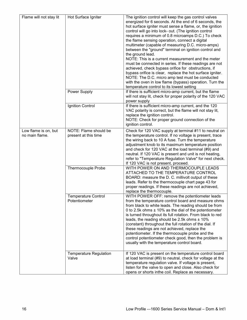
Low Profile -–1600 Series Service Manual – Dom & Int’l16
Hot Surface Igniter The ignition control will keep the gas control valvesenergized for 6 seconds. At the end of 6 seconds, thehot surface igniter must sense a flame, or, the ignitioncontrol will go into lock- out. (The ignition controlrequires a minimum of 0.8 microamps D.C.) To checkthe flame sensing operation, connect a digitalmultimeter (capable of measuring D.C. micro-amps)between the "ground" terminal on ignition control andthe ground lead.NOTE: This is a current measurement and the metermust be connected in series. If these readings are notachieved, check bypass orifice for obstructions, ifbypass orifice is clear, replace the hot surface igniter.NOTE: The D.C. micro amp test must be conductedwith the oven in low flame (bypass) operation. Turn thetemperature control to its lowest setting
Power Supply If there is sufficient micro-amp current, but the flamewill not stay lit, check for proper polarity of the 120 VACpower supply
Flame will not stay lit
Ignition Control If there is sufficient micro-amp current, and the 120VAC polarity is correct, but the flame will not stay lit,replace the ignition control.NOTE: Check for proper ground connection of theignition control.
NOTE: Flame should bepresent at this time
Check for 120 VAC supply at terminal #11 to neutral onthe temperature control. If no voltage is present, tracethe wiring back to 10 A fuse. Turn the temperatureadjustment knob to its maximum temperature positionand check for 120 VAC at the load terminal (#9) andneutral. If 120 VAC is present and unit is not heating,refer to "Temperature Regulation Valve" for next check.If 120 VAC is not present, proceed.
Thermocouple Probe WITH POWER ON AND THERMOCOUPLE LEADSATTACHED TO THE TEMPERATURE CONTROLBOARD: measure the D. C. millivolt output of theseleads. Refer to the thermocouple chart page 43 forproper readings. If these readings are not achieved,replace the thermocouple.
Temperature ControlPotentiometer
WITH POWER OFF: remove the potentiometer leadsfrom the temperature control board and measure ohmsfrom black to white leads. The reading should be from0 to 2.5k ohms ± 10% as the dial of the potentiometeris turned throughout its full rotation. From black to redleads, the reading should be 2.5k ohms ± 10%(constant) throughout the full rotation of the dial. Ifthese readings are not achieved, replace thepotentiometer. If the thermocouple probe and thecontrol potentiometer check good, then the problem isusually with the temperature control board.
Low flame is on, butno main flame.
Temperature RegulationValve
If 120 VAC is present on the temperature control boardat load terminal (#9) to neutral, check for voltage at thetemperature regulation valve. If voltage is present,listen for the valve to open and close. Also check foropens or shorts inthe coil. Replace as necessary.
Low Profile -–1600 Series Service Manual – Dom & Int’l 17
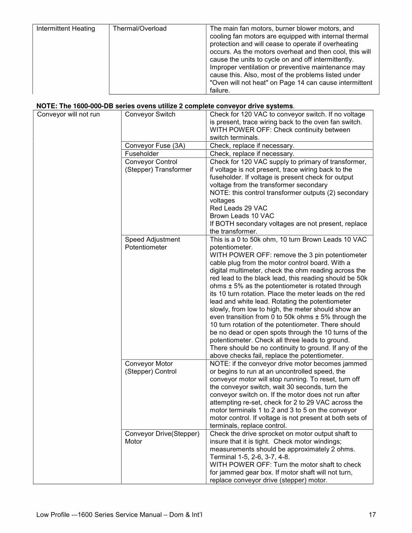
Intermittent Heating Thermal/Overload The main fan motors, burner blower motors, andcooling fan motors are equipped with internal thermalprotection and will cease to operate if overheatingoccurs. As the motors overheat and then cool, this willcause the units to cycle on and off intermittently.Improper ventilation or preventive maintenance maycause this. Also, most of the problems listed under"Oven will not heat" on Page 14 can cause intermittentfailure.
NOTE: The 1600-000-DB series ovens utilize 2 complete conveyor drive systems.Conveyor Switch Check for 120 VAC to conveyor switch. If no voltage
is present, trace wiring back to the oven fan switch.WITH POWER OFF: Check continuity betweenswitch terminals.
Conveyor Fuse (3A) Check, replace if necessary.Fuseholder Check, replace if necessary.Conveyor Control(Stepper) Transformer
Check for 120 VAC supply to primary of transformer,if voltage is not present, trace wiring back to thefuseholder. If voltage is present check for outputvoltage from the transformer secondaryNOTE: this control transformer outputs (2) secondaryvoltagesRed Leads 29 VACBrown Leads 10 VACIf BOTH secondary voltages are not present, replacethe transformer.
Speed AdjustmentPotentiometer
This is a 0 to 50k ohm, 10 turn Brown Leads 10 VACpotentiometer.WITH POWER OFF: remove the 3 pin potentiometercable plug from the motor control board. With adigital multimeter, check the ohm reading across thered lead to the black lead, this reading should be 50kohms ± 5% as the potentiometer is rotated throughits 10 turn rotation. Place the meter leads on the redlead and white lead. Rotating the potentiometerslowly, from low to high, the meter should show aneven transition from 0 to 50k ohms ± 5% through the10 turn rotation of the potentiometer. There shouldbe no dead or open spots through the 10 turns of thepotentiometer. Check all three leads to ground.There should be no continuity to ground. If any of theabove checks fail, replace the potentiometer.
Conveyor Motor(Stepper) Control
NOTE: if the conveyor drive motor becomes jammedor begins to run at an uncontrolled speed, theconveyor motor will stop running. To reset, turn offthe conveyor switch, wait 30 seconds, turn theconveyor switch on. If the motor does not run afterattempting re-set, check for 2 to 29 VAC across themotor terminals 1 to 2 and 3 to 5 on the conveyormotor control. If voltage is not present at both sets ofterminals, replace control.
Conveyor will not run
Conveyor Drive(Stepper)Motor
Check the drive sprocket on motor output shaft toinsure that it is tight. Check motor windings;measurements should be approximately 2 ohms.Terminal 1-5, 2-6, 3-7, 4-8.WITH POWER OFF: Turn the motor shaft to checkfor jammed gear box. If motor shaft will not turn,replace conveyor drive (stepper) motor.
Low Profile -–1600 Series Service Manual – Dom & Int’l18
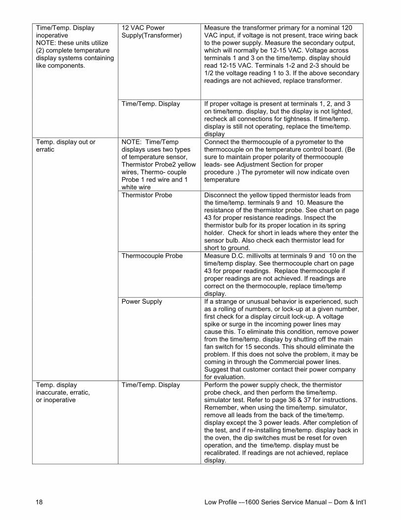
12 VAC PowerSupply(Transformer)
Measure the transformer primary for a nominal 120VAC input, if voltage is not present, trace wiring backto the power supply. Measure the secondary output,which will normally be 12-15 VAC. Voltage acrossterminals 1 and 3 on the time/temp. display shouldread 12-15 VAC. Terminals 1-2 and 2-3 should be1/2 the voltage reading 1 to 3. If the above secondaryreadings are not achieved, replace transformer.
Time/Temp. DisplayinoperativeNOTE: these units utilize(2) complete temperaturedisplay systems containinglike components.
Time/Temp. Display If proper voltage is present at terminals 1, 2, and 3on time/temp. display, but the display is not lighted,recheck all connections for tightness. If time/temp.display is still not operating, replace the time/temp.display
NOTE: Time/Tempdisplays uses two typesof temperature sensor,Thermistor Probe2 yellowwires, Thermo- coupleProbe 1 red wire and 1white wire
Connect the thermocouple of a pyrometer to thethermocouple on the temperature control board. (Besure to maintain proper polarity of thermocoupleleads- see Adjustment Section for properprocedure .) The pyrometer will now indicate oventemperature
Thermistor Probe Disconnect the yellow tipped thermistor leads fromthe time/temp. terminals 9 and 10. Measure theresistance of the thermistor probe. See chart on page43 for proper resistance readings. Inspect thethermistor bulb for its proper location in its springholder. Check for short in leads where they enter thesensor bulb. Also check each thermistor lead forshort to ground.
Thermocouple Probe Measure D.C. millivolts at terminals 9 and 10 on thetime/temp display. See thermocouple chart on page43 for proper readings. Replace thermocouple ifproper readings are not achieved. If readings arecorrect on the thermocouple, replace time/tempdisplay.
Temp. display out orerratic
Power Supply If a strange or unusual behavior is experienced, suchas a rolling of numbers, or lock-up at a given number,first check for a display circuit lock-up. A voltagespike or surge in the incoming power lines maycause this. To eliminate this condition, remove powerfrom the time/temp. display by shutting off the mainfan switch for 15 seconds. This should eliminate theproblem. If this does not solve the problem, it may becoming in through the Commercial power lines.Suggest that customer contact their power companyfor evaluation.
Temp. displayinaccurate, erratic,or inoperative
Time/Temp. Display Perform the power supply check, the thermistorprobe check, and then perform the time/temp.simulator test. Refer to page 36 & 37 for instructions.Remember, when using the time/temp. simulator,remove all leads from the back of the time/temp.display except the 3 power leads. After completion ofthe test, and if re-installing time/temp. display back inthe oven, the dip switches must be reset for ovenoperation, and the time/temp. display must berecalibrated. If readings are not achieved, replacedisplay.
Low Profile -–1600 Series Service Manual – Dom & Int’l 19
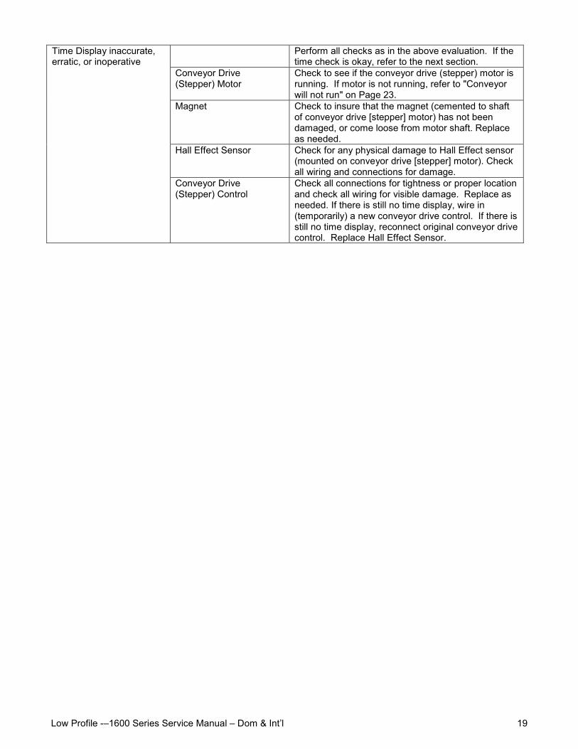
Perform all checks as in the above evaluation. If thetime check is okay, refer to the next section.
Conveyor Drive(Stepper) Motor
Check to see if the conveyor drive (stepper) motor isrunning. If motor is not running, refer to "Conveyorwill not run" on Page 23.
Magnet Check to insure that the magnet (cemented to shaftof conveyor drive [stepper] motor) has not beendamaged, or come loose from motor shaft. Replaceas needed.
Hall Effect Sensor Check for any physical damage to Hall Effect sensor(mounted on conveyor drive [stepper] motor). Checkall wiring and connections for damage.
Time Display inaccurate,erratic, or inoperative
Conveyor Drive(Stepper) Control
Check all connections for tightness or proper locationand check all wiring for visible damage. Replace asneeded. If there is still no time display, wire in(temporarily) a new conveyor drive control. If there isstill no time display, reconnect original conveyor drivecontrol. Replace Hall Effect Sensor.
Low Profile -–1600 Series Service Manual – Dom & Int’l20
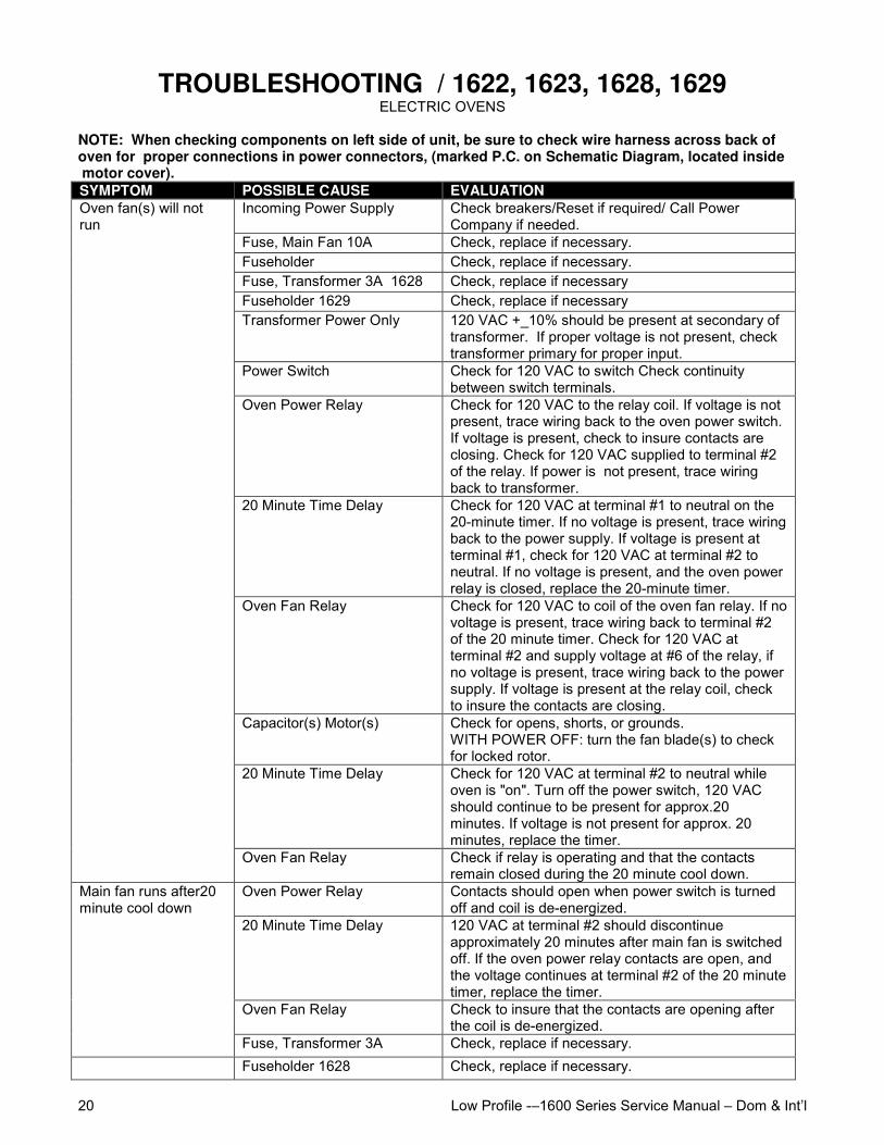
TROUBLESHOOTING / 1622, 1623, 1628, 1629ELECTRIC OVENS
NOTE: When checking components on left side of unit, be sure to check wire harness across back ofoven for proper connections in power connectors, (marked P.C. on Schematic Diagram, located inside motor cover).SYMPTOM POSSIBLE CAUSE EVALUATION
Incoming Power Supply Check breakers/Reset if required/ Call PowerCompany if needed.
Fuse, Main Fan 10A Check, replace if necessary.Fuseholder Check, replace if necessary.Fuse, Transformer 3A 1628 Check, replace if necessaryFuseholder 1629 Check, replace if necessaryTransformer Power Only 120 VAC +_10% should be present at secondary of
transformer. If proper voltage is not present, checktransformer primary for proper input.
Power Switch Check for 120 VAC to switch Check continuitybetween switch terminals.
Oven Power Relay Check for 120 VAC to the relay coil. If voltage is notpresent, trace wiring back to the oven power switch.If voltage is present, check to insure contacts areclosing. Check for 120 VAC supplied to terminal #2of the relay. If power is not present, trace wiringback to transformer.
20 Minute Time Delay Check for 120 VAC at terminal #1 to neutral on the20-minute timer. If no voltage is present, trace wiringback to the power supply. If voltage is present atterminal #1, check for 120 VAC at terminal #2 toneutral. If no voltage is present, and the oven powerrelay is closed, replace the 20-minute timer.
Oven Fan Relay Check for 120 VAC to coil of the oven fan relay. If novoltage is present, trace wiring back to terminal #2of the 20 minute timer. Check for 120 VAC atterminal #2 and supply voltage at #6 of the relay, ifno voltage is present, trace wiring back to the powersupply. If voltage is present at the relay coil, checkto insure the contacts are closing.
Capacitor(s) Motor(s) Check for opens, shorts, or grounds.WITH POWER OFF: turn the fan blade(s) to checkfor locked rotor.
20 Minute Time Delay Check for 120 VAC at terminal #2 to neutral whileoven is "on". Turn off the power switch, 120 VACshould continue to be present for approx.20minutes. If voltage is not present for approx. 20minutes, replace the timer.
Oven fan(s) will notrun
Oven Fan Relay Check if relay is operating and that the contactsremain closed during the 20 minute cool down.
Oven Power Relay Contacts should open when power switch is turnedoff and coil is de-energized.
20 Minute Time Delay 120 VAC at terminal #2 should discontinueapproximately 20 minutes after main fan is switchedoff. If the oven power relay contacts are open, andthe voltage continues at terminal #2 of the 20 minutetimer, replace the timer.
Oven Fan Relay Check to insure that the contacts are opening afterthe coil is de-energized.
Main fan runs after20minute cool down
Fuse, Transformer 3A Check, replace if necessary.Fuseholder 1628 Check, replace if necessary.
Low Profile -–1600 Series Service Manual – Dom & Int’l 21
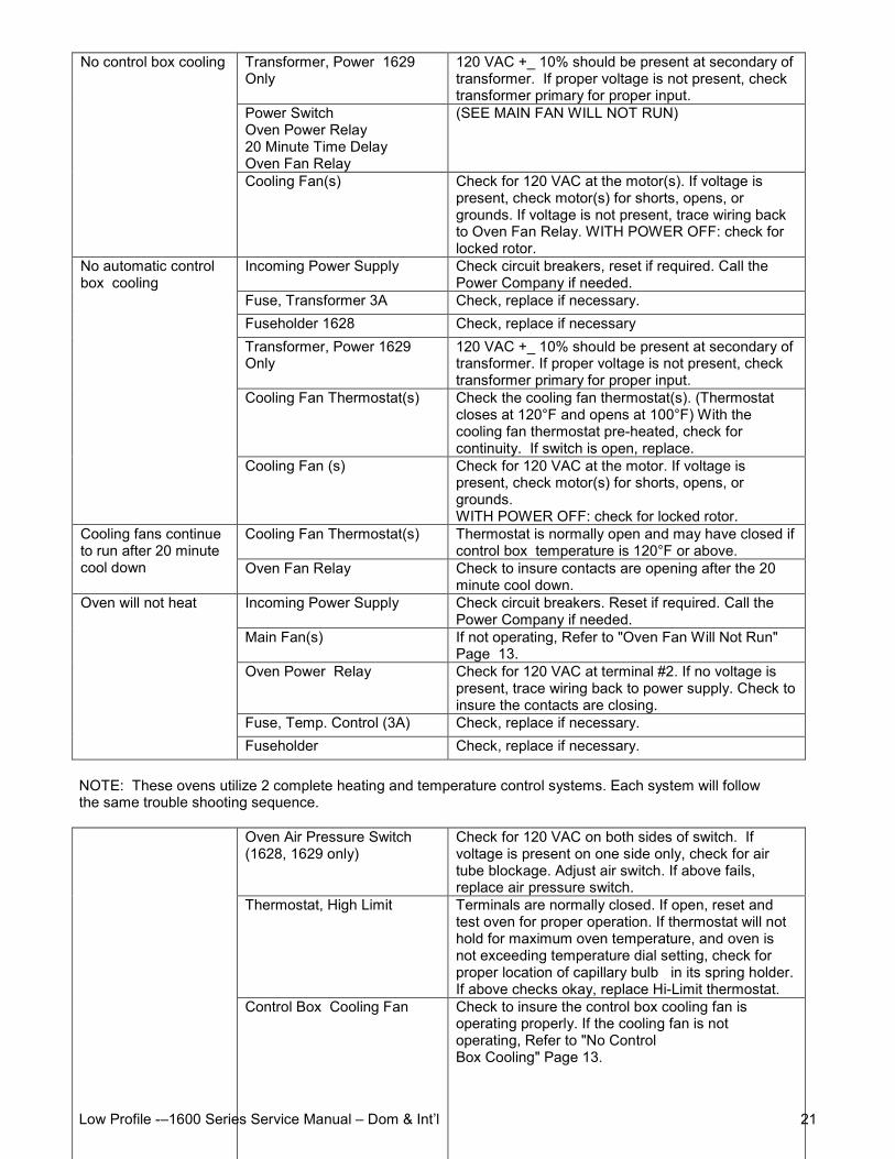
Transformer, Power 1629Only
120 VAC +_ 10% should be present at secondary oftransformer. If proper voltage is not present, checktransformer primary for proper input.
Power SwitchOven Power Relay20 Minute Time DelayOven Fan Relay
(SEE MAIN FAN WILL NOT RUN)
No control box cooling
Cooling Fan(s) Check for 120 VAC at the motor(s). If voltage ispresent, check motor(s) for shorts, opens, orgrounds. If voltage is not present, trace wiring backto Oven Fan Relay. WITH POWER OFF: check forlocked rotor.
Incoming Power Supply Check circuit breakers, reset if required. Call thePower Company if needed.
Fuse, Transformer 3A Check, replace if necessary.Fuseholder 1628 Check, replace if necessaryTransformer, Power 1629Only
120 VAC +_ 10% should be present at secondary oftransformer. If proper voltage is not present, checktransformer primary for proper input.
Cooling Fan Thermostat(s) Check the cooling fan thermostat(s). (Thermostatcloses at 120°F and opens at 100°F) With thecooling fan thermostat pre-heated, check forcontinuity. If switch is open, replace.
No automatic controlbox cooling
Cooling Fan (s) Check for 120 VAC at the motor. If voltage ispresent, check motor(s) for shorts, opens, orgrounds.WITH POWER OFF: check for locked rotor.
Cooling Fan Thermostat(s) Thermostat is normally open and may have closed ifcontrol box temperature is 120°F or above.
Cooling fans continueto run after 20 minutecool down Oven Fan Relay Check to insure contacts are opening after the 20
minute cool down.Incoming Power Supply Check circuit breakers. Reset if required. Call the
Power Company if needed.Main Fan(s) If not operating, Refer to "Oven Fan Will Not Run"
Page 13.Oven Power Relay Check for 120 VAC at terminal #2. If no voltage is
present, trace wiring back to power supply. Check toinsure the contacts are closing.
Fuse, Temp. Control (3A) Check, replace if necessary.
Oven will not heat
Fuseholder Check, replace if necessary.
NOTE: These ovens utilize 2 complete heating and temperature control systems. Each system will followthe same trouble shooting sequence.
Oven Air Pressure Switch(1628, 1629 only)
Check for 120 VAC on both sides of switch. Ifvoltage is present on one side only, check for airtube blockage. Adjust air switch. If above fails,replace air pressure switch.
Thermostat, High Limit Terminals are normally closed. If open, reset andtest oven for proper operation. If thermostat will nothold for maximum oven temperature, and oven isnot exceeding temperature dial setting, check forproper location of capillary bulb in its spring holder.If above checks okay, replace Hi-Limit thermostat.
Control Box Cooling Fan Check to insure the control box cooling fan isoperating properly. If the cooling fan is notoperating, Refer to "No ControlBox Cooling" Page 13.
Low Profile -–1600 Series Service Manual – Dom & Int’l22
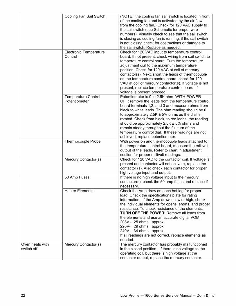
Cooling Fan Sail Switch (NOTE: the cooling fan sail switch is located in frontof the cooling fan and is activated by the air flowfrom the cooling fan.) Check for 120 VAC supply tothe sail switch (see Schematic for proper wirenumbers). Visually check to see that the sail switchis closing as cooling fan is running, if the sail switchis not closing check for obstructions or damage tothe sail switch. Replace as needed.
Electronic TemperatureControl
Check for 120 VAC input to temperature controlboard. If not present, check wiring from sail switch totemperature control board. Turn the temperatureadjustment dial to the maximum temperatureposition. Check for 120 VAC at coil of mercurycontactor(s). Next, short the leads of thermocoupleon the temperature control board, check for 120VAC at coil of mercury contactor(s). If voltage is notpresent, replace temperature control board. Ifvoltage is present proceed.
Temperature ControlPotentiometer
Potentiometer is 0 to 2.5K ohm. WITH POWEROFF: remove the leads from the temperature controlboard terminals 1,2, and 3 and measure ohms fromblack to white leads. The ohm reading should be 0to approximately 2.5K ± 5% ohms as the dial isrotated. Check from black, to red leads, the readingshould be approximately 2.5K ± 5% ohms andremain steady throughout the full turn of thetemperature control dial. If these readings are notachieved, replace potentiometer.
Thermocouple Probe With power on and thermocouple leads attached tothe temperature control board, measure the millivoltoutput of the leads. Refer to chart in adjustmentsection for proper millivolt readings.
Mercury Contactor(s) Check for 120 VAC to the contactor coil. If voltage ispresent and contactor will not activate, replace thecontactor (s). Also check each contactor for properhigh voltage input and output.
50 Amp Fuses If there is no high voltage input to the mercurycontactor(s), check the 50 amp fuses and replace ifnecessary.
Heater Elements Check the Amp draw on each hot leg for properload. Check the specifications plate for ratinginformation. If the Amp draw is low or high, checkthe individual elements for opens, shorts, and properresistance. To check resistance of the elements,TURN OFF THE POWER! Remove all leads fromthe elements and use an accurate digital VOM.208V - 25 ohms approx.220V- 29 ohms approx.240V - 34 ohms approx.If all readings are not correct, replace elements asneeded.
Oven heats withswitch off
Mercury Contactor(s) The mercury contactor has probably malfunctionedin the closed position. If there is no voltage to theoperating coil, but there is high voltage at thecontactor output, replace the mercury contactor.
Low Profile -–1600 Series Service Manual – Dom & Int’l 23
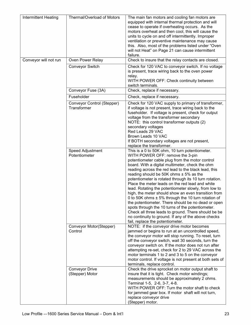
Intermittent Heating Thermal/Overload of Motors The main fan motors and cooling fan motors areequipped with internal thermal protection and willcease to operate if overheating occurs. As themotors overheat and then cool, this will cause theunits to cycle on and off intermittently. Improperventilation or preventive maintenance may causethis. Also, most of the problems listed under “Ovenwill not Heat” on Page 21 can cause intermittentfailure.
Oven Power Relay Check to insure that the relay contacts are closed.Conveyor Switch Check for 120 VAC to conveyor switch. If no voltage
is present, trace wiring back to the oven powerrelay.WITH POWER OFF: Check continuity betweenswitch terminals.
Conveyor Fuse (3A) Check, replace if necessary.Fuseholder Check, replace if necessary.Conveyor Control (Stepper)Transformer
Check for 120 VAC supply to primary of transformer,if voltage is not present, trace wiring back to thefuseholder. If voltage is present, check for outputvoltage from the transformer secondaryNOTE: this control transformer outputs (2)secondary voltagesRed Leads 29 VACBrown Leads 10 VACIf BOTH secondary voltages are not present,replace the transformer.
Speed AdjustmentPotentiometer
This is a 0 to 50K ohm, 10 turn potentiometer.WITH POWER OFF: remove the 3-pinpotentiometer cable plug from the motor controlboard. With a digital multimeter, check the ohmreading across the red lead to the black lead, thisreading should be 50K ohms ± 5% as thepotentiometer is rotated through its 10 turn rotation.Place the meter leads on the red lead and whitelead. Rotating the potentiometer slowly, from low tohigh, the meter should show an even transition from0 to 50K ohms ± 5% through the 10 turn rotation ofthe potentiometer. There should be no dead or openspots through the 10 turns of the potentiometer.Check all three leads to ground. There should be beno continuity to ground. If any of the above checksfail, replace the potentiometer.
Conveyor Motor(Stepper)Control
NOTE: if the conveyor drive motor becomesjammed or begins to run at an uncontrolled speed,the conveyor motor will stop running. To reset, turnoff the conveyor switch, wait 30 seconds, turn theconveyor switch on. If the motor does not run afterattempting re-set, check for 2 to 29 VAC across themotor terminals 1 to 2 and 3 to 5 on the conveyormotor control. If voltage is not present at both sets ofterminals, replace control.
Conveyor will not run
Conveyor Drive(Stepper) Motor
Check the drive sprocket on motor output shaft toinsure that it is tight. Check motor windings;measurements should be approximately 2 ohms.Terminal 1-5, 2-6, 3-7, 4-8.WITH POWER OFF: Turn the motor shaft to checkfor jammed gear box. If motor shaft will not turn,replace conveyor drive(Stepper) motor.
Low Profile -–1600 Series Service Manual – Dom & Int’l24
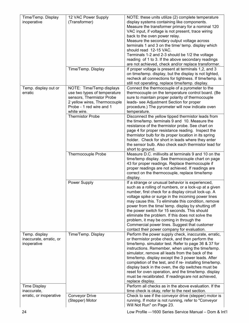
12 VAC Power Supply(Transformer)
NOTE: these units utilize (2) complete temperaturedisplay systems containing like components.Measure the transformer primary for a nominal 120VAC input, if voltage is not present, trace wiringback to the oven power relay.Measure the secondary output voltage acrossterminals 1 and 3 on the time/ temp. display whichshould read 12-15 VAC.Terminals 1-2 and 2-3 should be 1/2 the voltagereading of 1 to 3. If the above secondary readingsare not achieved, check and/or replace transformer.
Time/Temp. Displayinoperative
Time/Temp. Display If proper voltage is present at terminals 1,2, and 3on time/temp. display, but the display is not lighted,recheck all connections for tightness. If time/temp. isstill not operating, replace time/temp. display.
NOTE: Time/Temp displaysuse two types of temperaturesensors, Thermistor Probe2 yellow wires, ThermocoupleProbe - 1 red wire and 1white wire.
Connect the thermocouple of a pyrometer to thethermocouple on the temperature control board. (Besure to maintain proper polarity of thermocoupleleads- see Adjustment Section for properprocedure.) The pyrometer will now indicate oventemperature.
Thermistor Probe Disconnect the yellow tipped thermistor leads fromthe time/temp. terminals 9 and 10. Measure theresistance of the thermistor probe. See chart onpage 4 for proper resistance reading. Inspect thethermistor bulb for its proper location in its springholder. Check for short in leads where they enterthe sensor bulb. Also check each thermistor lead forshort to ground.
Thermocouple Probe Measure D.C. millivolts at terminals 9 and 10 on thetime/temp display. See thermocouple chart on page43 for proper readings. Replace thermocouple ifproper readings are not achieved. If readings arecorrect on the thermocouple, replace time/tempdisplay.
Temp. display out orerratic
Power Supply If a strange or unusual behavior is experienced,such as a rolling of numbers, or a lock-up at a givennumber, first check for a display circuit lock-up. Avoltage spike or surge in the incoming power linesmay cause this. To eliminate this condition, removepower from the time/ temp. display by shutting offthe power switch for 15 seconds. This shouldeliminate the problem. If this does not solve theproblem, it may be coming in through theCommercial power lines. Suggest that customercontact their power company for evaluation.
Temp. displayinaccurate, erratic, orinoperative
Perform the power supply check, inaccurate, erratic,or thermistor probe check, and then perform thetime/temp. simulator test. Refer to page 36 & 37 forinstructions. Remember, when using the time/temp.simulator, remove all leads from the back of thetime/temp. display except the 3 power leads. Aftercompletion of the test, and if re- installing time/temp.display back in the oven, the dip switches must bereset for oven operation, and the time/temp. displaymust be recalibrated. If readingsare not achieved,replace display.
Time/Temp. Display
Perform all checks as in the above evaluation. If thetime check is okay, refer to the next section.
Time Displayinaccurate,erratic, or inoperative Conveyor Drive
(Stepper) MotorCheck to see if the conveyor drive (stepper) motor isrunning. If motor is not running, refer to "ConveyorWill Not Run" on Page 23.
Low Profile -–1600 Series Service Manual – Dom & Int’l 25
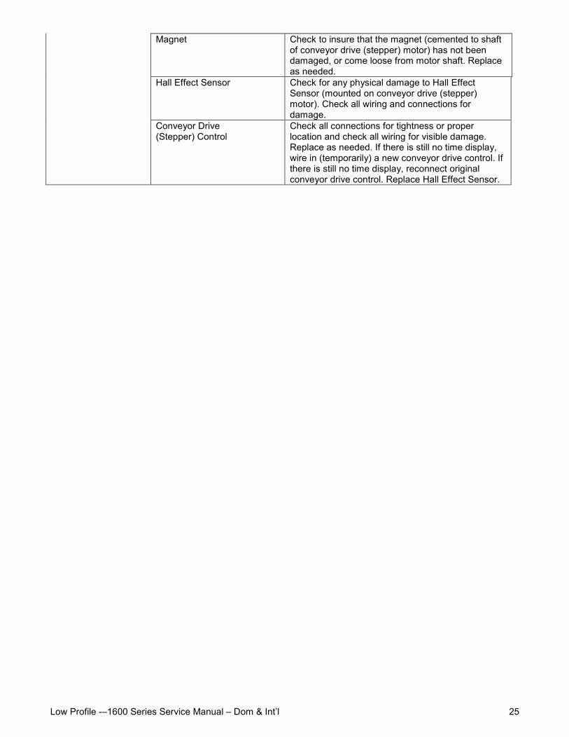
Magnet Check to insure that the magnet (cemented to shaftof conveyor drive (stepper) motor) has not beendamaged, or come loose from motor shaft. Replaceas needed.
Hall Effect Sensor Check for any physical damage to Hall EffectSensor (mounted on conveyor drive (stepper)motor). Check all wiring and connections fordamage.
Conveyor Drive(Stepper) Control
Check all connections for tightness or properlocation and check all wiring for visible damage.Replace as needed. If there is still no time display,wire in (temporarily) a new conveyor drive control. Ifthere is still no time display, reconnect originalconveyor drive control. Replace Hall Effect Sensor.
Low Profile -–1600 Series Service Manual – Dom & Int’l26
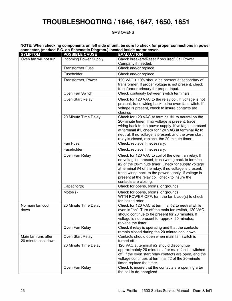
TROUBLESHOOTING / 1646, 1647, 1650, 1651GAS OVENS
NOTE: When checking components on left side of unit, be sure to check for proper connections in powerconnector, (marked P.C. on Schematic Diagram.) located inside motor cover.SYMPTOM POSSIBLE CAUSE EVALUATION
Incoming Power Supply Check breakers/Reset if required/ Call PowerCompany if needed.
Transformer Fuse Check and/or replaceFuseholder Check and/or replace.Transformer, Power 120 VAC ± 10% should be present at secondary of
transformer. If proper voltage is not present, checktransformer primary for proper input.
Oven Fan Switch Check continuity between switch terminals.Oven Start Relay Check for 120 VAC to the relay coil. If voltage is not
present, trace wiring back to the oven fan switch. Ifvoltage is present, check to insure contacts areclosing.
20 Minute Time Delay Check for 120 VAC at terminal #1 to neutral on the20-minute timer. If no voltage is present, tracewiring back to the power supply. If voltage is presentat terminal #1, check for 120 VAC at terminal #2 toneutral. If no voltage is present, and the oven startrelay is closed, replace the 20 minute timer.
Fan Fuse Check, replace if necessary.Fuseholder Check, replace if necessary.Oven Fan Relay Check for 120 VAC to coil of the oven fan relay. If
no voltage is present, trace wiring back to terminal#2 of the 20-minute timer. Check for supply voltageat terminal #4 of the relay, if no voltage is present,trace wiring back to the power supply. If voltage ispresent at the relay coil, check to insure thecontacts are closing.
Capacitor(s) Check for opens, shorts, or grounds.
Oven fan will not run
Motor(s) Check for opens, shorts, or grounds.WITH POWER OFF: turn the fan blade(s) to checkfor locked rotor.
20 Minute Time Delay Check for 120 VAC at terminal #2 to neutral whileoven is "on". Turn off the main fan switch, 120 VACshould continue to be present for 20 minutes. Ifvoltage is not present for approx. 20 minutes,replace the timer.
No main fan cooldown
Oven Fan Relay Check if relay is operating and that the contactsremain closed during the 20 minute cool down.
Oven Start Relay Contacts should open when main fan switch isturned off.
20 Minute Time Delay 120 VAC at terminal #2 should discontinueapproximately 20 minutes after main fan is switchedoff. If the oven start relay contacts are open, and thevoltage continues at terminal #2 of the 20-minutetimer, replace the timer.
Main fan runs after20 minute cool down
Oven Fan Relay Check to insure that the contacts are opening afterthe coil is de-energized.
Low Profile -–1600 Series Service Manual – Dom & Int’l 27
Fan SwitchOven Start Relay20 Minute Time Delay
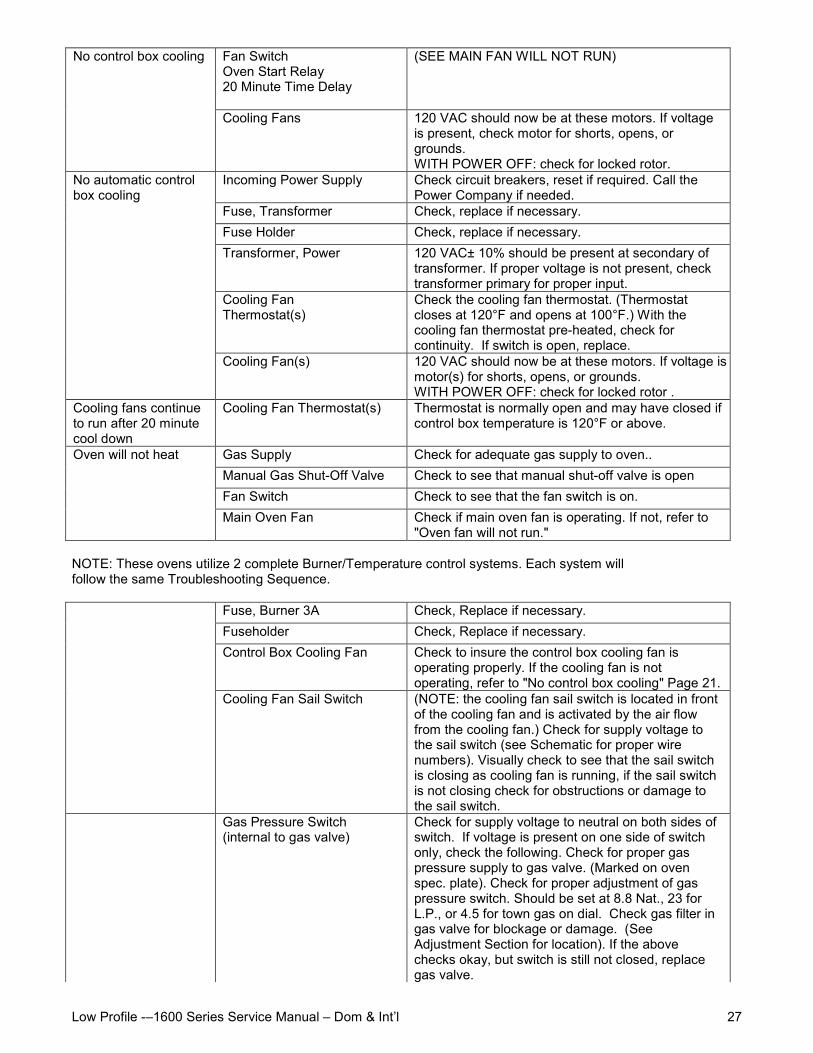
(SEE MAIN FAN WILL NOT RUN)No control box cooling
Cooling Fans 120 VAC should now be at these motors. If voltageis present, check motor for shorts, opens, orgrounds.WITH POWER OFF: check for locked rotor.
Incoming Power Supply Check circuit breakers, reset if required. Call thePower Company if needed.
Fuse, Transformer Check, replace if necessary.Fuse Holder Check, replace if necessary.Transformer, Power 120 VAC± 10% should be present at secondary of
transformer. If proper voltage is not present, checktransformer primary for proper input.
Cooling FanThermostat(s)
Check the cooling fan thermostat. (Thermostatcloses at 120°F and opens at 100°F.) With thecooling fan thermostat pre-heated, check forcontinuity. If switch is open, replace.
No automatic controlbox cooling
Cooling Fan(s) 120 VAC should now be at these motors. If voltage is present, checkmotor(s) for shorts, opens, or grounds.WITH POWER OFF: check for locked rotor .
Cooling fans continueto run after 20 minutecool down
Cooling Fan Thermostat(s) Thermostat is normally open and may have closed ifcontrol box temperature is 120°F or above.
Gas Supply Check for adequate gas supply to oven..Manual Gas Shut-Off Valve Check to see that manual shut-off valve is openFan Switch Check to see that the fan switch is on.
Oven will not heat
Main Oven Fan Check if main oven fan is operating. If not, refer to"Oven fan will not run."
NOTE: These ovens utilize 2 complete Burner/Temperature control systems. Each system willfollow the same Troubleshooting Sequence.
Fuse, Burner 3A Check, Replace if necessary.Fuseholder Check, Replace if necessary.Control Box Cooling Fan Check to insure the control box cooling fan is
operating properly. If the cooling fan is notoperating, refer to "No control box cooling" Page 21.
Cooling Fan Sail Switch (NOTE: the cooling fan sail switch is located in frontof the cooling fan and is activated by the air flowfrom the cooling fan.) Check for supply voltage tothe sail switch (see Schematic for proper wirenumbers). Visually check to see that the sail switchis closing as cooling fan is running, if the sail switchis not closing check for obstructions or damage tothe sail switch.
Gas Pressure Switch(internal to gas valve)
Check for supply voltage to neutral on both sides ofswitch. If voltage is present on one side of switchonly, check the following. Check for proper gaspressure supply to gas valve. (Marked on ovenspec. plate). Check for proper adjustment of gaspressure switch. Should be set at 8.8 Nat., 23 forL.P., or 4.5 for town gas on dial. Check gas filter ingas valve for blockage or damage. (SeeAdjustment Section for location). If the abovechecks okay, but switch is still not closed, replacegas valve.
Low Profile -–1600 Series Service Manual – Dom & Int’l28
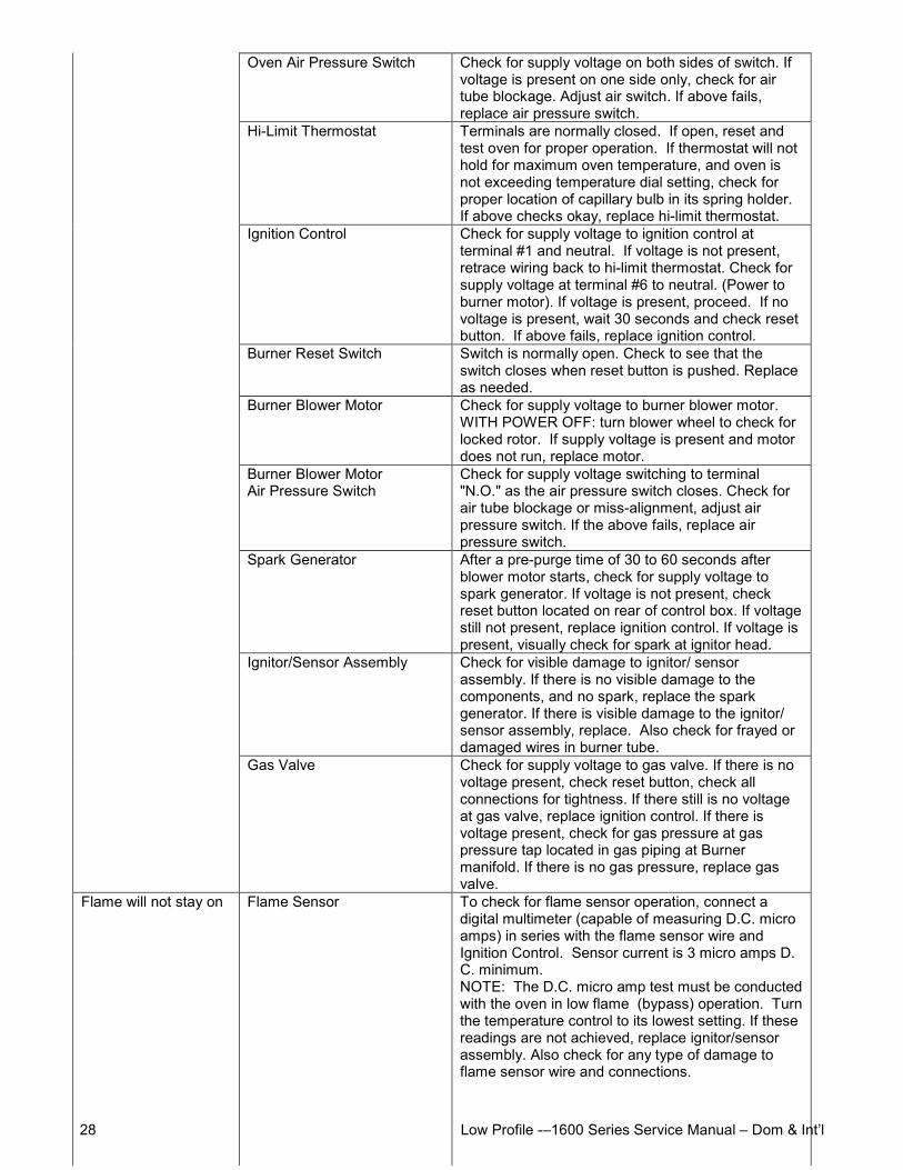
Oven Air Pressure Switch Check for supply voltage on both sides of switch. Ifvoltage is present on one side only, check for airtube blockage. Adjust air switch. If above fails,replace air pressure switch.
Hi-Limit Thermostat Terminals are normally closed. If open, reset andtest oven for proper operation. If thermostat will nothold for maximum oven temperature, and oven isnot exceeding temperature dial setting, check forproper location of capillary bulb in its spring holder.If above checks okay, replace hi-limit thermostat.
Ignition Control Check for supply voltage to ignition control atterminal #1 and neutral. If voltage is not present,retrace wiring back to hi-limit thermostat. Check forsupply voltage at terminal #6 to neutral. (Power toburner motor). If voltage is present, proceed. If novoltage is present, wait 30 seconds and check resetbutton. If above fails, replace ignition control.
Burner Reset Switch Switch is normally open. Check to see that theswitch closes when reset button is pushed. Replaceas needed.
Burner Blower Motor Check for supply voltage to burner blower motor.WITH POWER OFF: turn blower wheel to check forlocked rotor. If supply voltage is present and motordoes not run, replace motor.
Burner Blower MotorAir Pressure Switch
Check for supply voltage switching to terminal"N.O." as the air pressure switch closes. Check forair tube blockage or miss-alignment, adjust airpressure switch. If the above fails, replace airpressure switch.
Spark Generator After a pre-purge time of 30 to 60 seconds afterblower motor starts, check for supply voltage tospark generator. If voltage is not present, checkreset button located on rear of control box. If voltagestill not present, replace ignition control. If voltage ispresent, visually check for spark at ignitor head.
Ignitor/Sensor Assembly Check for visible damage to ignitor/ sensorassembly. If there is no visible damage to thecomponents, and no spark, replace the sparkgenerator. If there is visible damage to the ignitor/sensor assembly, replace. Also check for frayed ordamaged wires in burner tube.
Gas Valve Check for supply voltage to gas valve. If there is novoltage present, check reset button, check allconnections for tightness. If there still is no voltageat gas valve, replace ignition control. If there isvoltage present, check for gas pressure at gaspressure tap located in gas piping at Burnermanifold. If there is no gas pressure, replace gasvalve.
Flame will not stay on Flame Sensor To check for flame sensor operation, connect adigital multimeter (capable of measuring D.C. microamps) in series with the flame sensor wire andIgnition Control. Sensor current is 3 micro amps D.C. minimum.NOTE: The D.C. micro amp test must be conductedwith the oven in low flame (bypass) operation. Turnthe temperature control to its lowest setting. If thesereadings are not achieved, replace ignitor/sensorassembly. Also check for any type of damage toflame sensor wire and connections.
Low Profile -–1600 Series Service Manual – Dom & Int’l 29
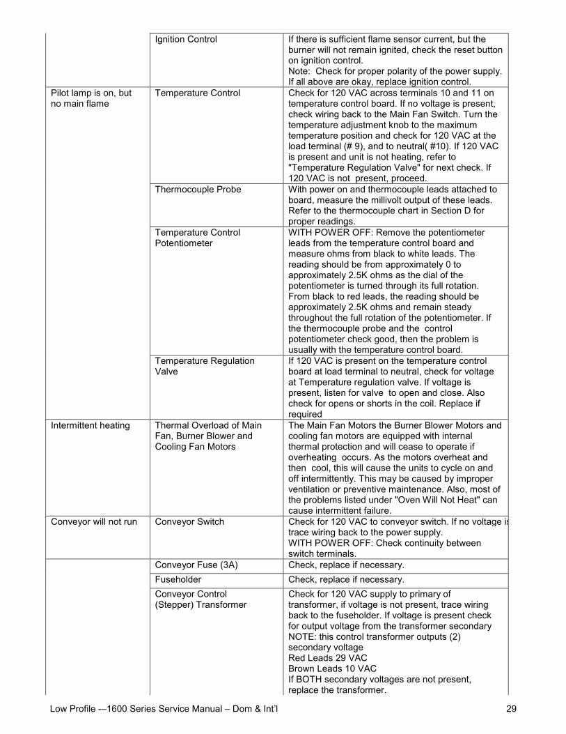
Ignition Control If there is sufficient flame sensor current, but theburner will not remain ignited, check the reset buttonon ignition control.Note: Check for proper polarity of the power supply.If all above are okay, replace ignition control.
Temperature Control Check for 120 VAC across terminals 10 and 11 ontemperature control board. If no voltage is present,check wiring back to the Main Fan Switch. Turn thetemperature adjustment knob to the maximumtemperature position and check for 120 VAC at theload terminal (# 9), and to neutral( #10). If 120 VACis present and unit is not heating, refer to"Temperature Regulation Valve" for next check. If120 VAC is not present, proceed.
Thermocouple Probe With power on and thermocouple leads attached toboard, measure the millivolt output of these leads.Refer to the thermocouple chart in Section D forproper readings.
Temperature ControlPotentiometer
WITH POWER OFF: Remove the potentiometerleads from the temperature control board andmeasure ohms from black to white leads. Thereading should be from approximately 0 toapproximately 2.5K ohms as the dial of thepotentiometer is turned through its full rotation.From black to red leads, the reading should beapproximately 2.5K ohms and remain steadythroughout the full rotation of the potentiometer. Ifthe thermocouple probe and the controlpotentiometer check good, then the problem isusually with the temperature control board.
Pilot lamp is on, butno main flame
Temperature RegulationValve
If 120 VAC is present on the temperature controlboard at load terminal to neutral, check for voltageat Temperature regulation valve. If voltage ispresent, listen for valve to open and close. Alsocheck for opens or shorts in the coil. Replace ifrequired
Intermittent heating Thermal Overload of MainFan, Burner Blower andCooling Fan Motors
The Main Fan Motors the Burner Blower Motors andcooling fan motors are equipped with internalthermal protection and will cease to operate ifoverheating occurs. As the motors overheat andthen cool, this will cause the units to cycle on andoff intermittently. This may be caused by improperventilation or preventive maintenance. Also, most ofthe problems listed under "Oven Will Not Heat" cancause intermittent failure.
Conveyor will not run Conveyor Switch Check for 120 VAC to conveyor switch. If no voltage is present,trace wiring back to the power supply.WITH POWER OFF: Check continuity betweenswitch terminals.
Conveyor Fuse (3A) Check, replace if necessary.Fuseholder Check, replace if necessary.Conveyor Control(Stepper) Transformer
Check for 120 VAC supply to primary oftransformer, if voltage is not present, trace wiringback to the fuseholder. If voltage is present checkfor output voltage from the transformer secondaryNOTE: this control transformer outputs (2)secondary voltageRed Leads 29 VACBrown Leads 10 VACIf BOTH secondary voltages are not present,replace the transformer.
Low Profile -–1600 Series Service Manual – Dom & Int’l30
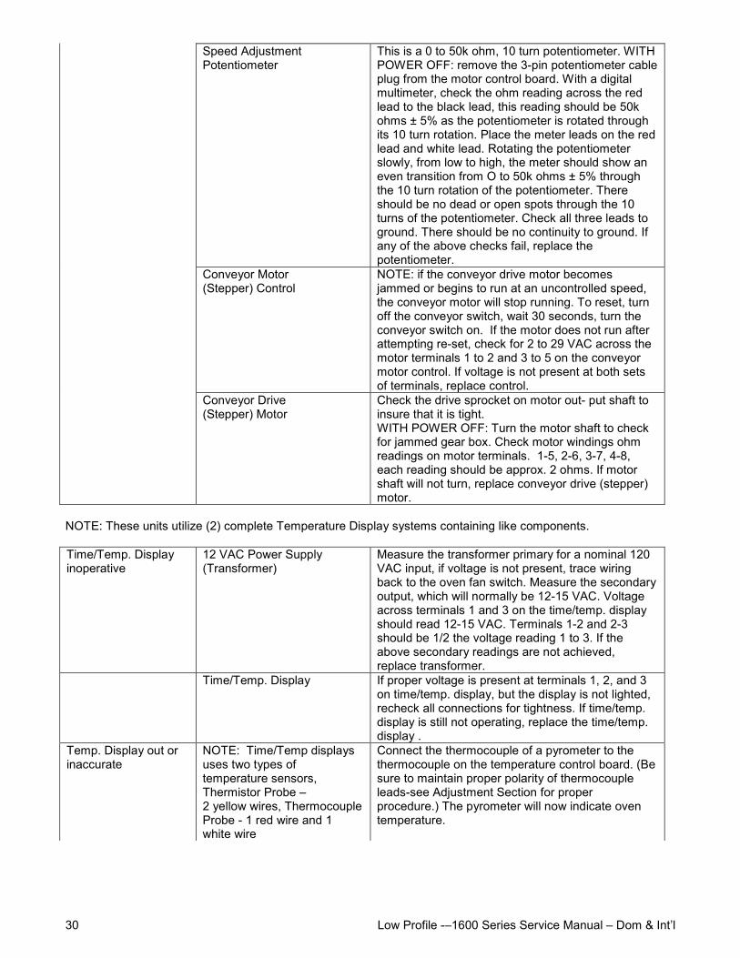
Speed AdjustmentPotentiometer
This is a 0 to 50k ohm, 10 turn potentiometer. WITHPOWER OFF: remove the 3-pin potentiometer cableplug from the motor control board. With a digitalmultimeter, check the ohm reading across the redlead to the black lead, this reading should be 50kohms ± 5% as the potentiometer is rotated throughits 10 turn rotation. Place the meter leads on the redlead and white lead. Rotating the potentiometerslowly, from low to high, the meter should show aneven transition from O to 50k ohms ± 5% throughthe 10 turn rotation of the potentiometer. Thereshould be no dead or open spots through the 10turns of the potentiometer. Check all three leads toground. There should be no continuity to ground. Ifany of the above checks fail, replace thepotentiometer.
Conveyor Motor(Stepper) Control
NOTE: if the conveyor drive motor becomesjammed or begins to run at an uncontrolled speed,the conveyor motor will stop running. To reset, turnoff the conveyor switch, wait 30 seconds, turn theconveyor switch on. If the motor does not run afterattempting re-set, check for 2 to 29 VAC across themotor terminals 1 to 2 and 3 to 5 on the conveyormotor control. If voltage is not present at both setsof terminals, replace control.
Conveyor Drive(Stepper) Motor
Check the drive sprocket on motor out- put shaft toinsure that it is tight.WITH POWER OFF: Turn the motor shaft to checkfor jammed gear box. Check motor windings ohmreadings on motor terminals. 1-5, 2-6, 3-7, 4-8,each reading should be approx. 2 ohms. If motorshaft will not turn, replace conveyor drive (stepper)motor.
NOTE: These units utilize (2) complete Temperature Display systems containing like components.
Time/Temp. Displayinoperative
12 VAC Power Supply(Transformer)
Measure the transformer primary for a nominal 120VAC input, if voltage is not present, trace wiringback to the oven fan switch. Measure the secondaryoutput, which will normally be 12-15 VAC. Voltageacross terminals 1 and 3 on the time/temp. displayshould read 12-15 VAC. Terminals 1-2 and 2-3should be 1/2 the voltage reading 1 to 3. If theabove secondary readings are not achieved,replace transformer.
Time/Temp. Display If proper voltage is present at terminals 1, 2, and 3on time/temp. display, but the display is not lighted,recheck all connections for tightness. If time/temp.display is still not operating, replace the time/temp.display .
Temp. Display out orinaccurate
NOTE: Time/Temp displaysuses two types oftemperature sensors,Thermistor Probe –2 yellow wires, ThermocoupleProbe - 1 red wire and 1white wire
Connect the thermocouple of a pyrometer to thethermocouple on the temperature control board. (Besure to maintain proper polarity of thermocoupleleads-see Adjustment Section for properprocedure.) The pyrometer will now indicate oventemperature.
Low Profile -–1600 Series Service Manual – Dom & Int’l 31
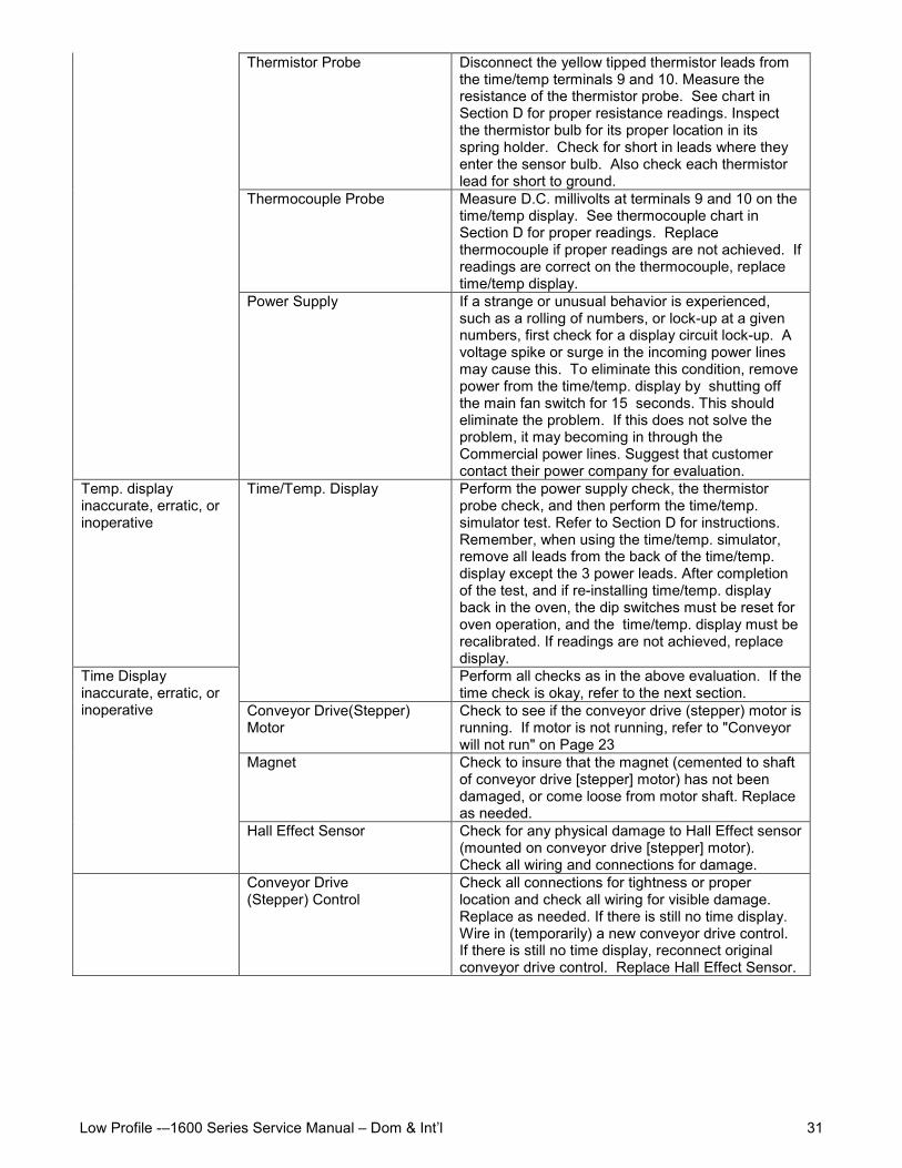
Thermistor Probe Disconnect the yellow tipped thermistor leads fromthe time/temp terminals 9 and 10. Measure theresistance of the thermistor probe. See chart inSection D for proper resistance readings. Inspectthe thermistor bulb for its proper location in itsspring holder. Check for short in leads where theyenter the sensor bulb. Also check each thermistorlead for short to ground.
Thermocouple Probe Measure D.C. millivolts at terminals 9 and 10 on thetime/temp display. See thermocouple chart inSection D for proper readings. Replacethermocouple if proper readings are not achieved. Ifreadings are correct on the thermocouple, replacetime/temp display.
Power Supply If a strange or unusual behavior is experienced,such as a rolling of numbers, or lock-up at a givennumbers, first check for a display circuit lock-up. Avoltage spike or surge in the incoming power linesmay cause this. To eliminate this condition, removepower from the time/temp. display by shutting offthe main fan switch for 15 seconds. This shouldeliminate the problem. If this does not solve theproblem, it may becoming in through theCommercial power lines. Suggest that customercontact their power company for evaluation.
Temp. displayinaccurate, erratic, orinoperative
Perform the power supply check, the thermistorprobe check, and then perform the time/temp.simulator test. Refer to Section D for instructions.Remember, when using the time/temp. simulator,remove all leads from the back of the time/temp.display except the 3 power leads. After completionof the test, and if re-installing time/temp. displayback in the oven, the dip switches must be reset foroven operation, and the time/temp. display must berecalibrated. If readings are not achieved, replacedisplay.
Time/Temp. Display
Perform all checks as in the above evaluation. If thetime check is okay, refer to the next section.
Conveyor Drive(Stepper)Motor
Check to see if the conveyor drive (stepper) motor isrunning. If motor is not running, refer to "Conveyorwill not run" on Page 23
Magnet Check to insure that the magnet (cemented to shaftof conveyor drive [stepper] motor) has not beendamaged, or come loose from motor shaft. Replaceas needed.
Time Displayinaccurate, erratic, orinoperative
Hall Effect Sensor Check for any physical damage to Hall Effect sensor(mounted on conveyor drive [stepper] motor).Check all wiring and connections for damage.
Conveyor Drive(Stepper) Control
Check all connections for tightness or properlocation and check all wiring for visible damage.Replace as needed. If there is still no time display.Wire in (temporarily) a new conveyor drive control.If there is still no time display, reconnect originalconveyor drive control. Replace Hall Effect Sensor.
Low Profile -–1600 Series Service Manual – Dom & Int’l32
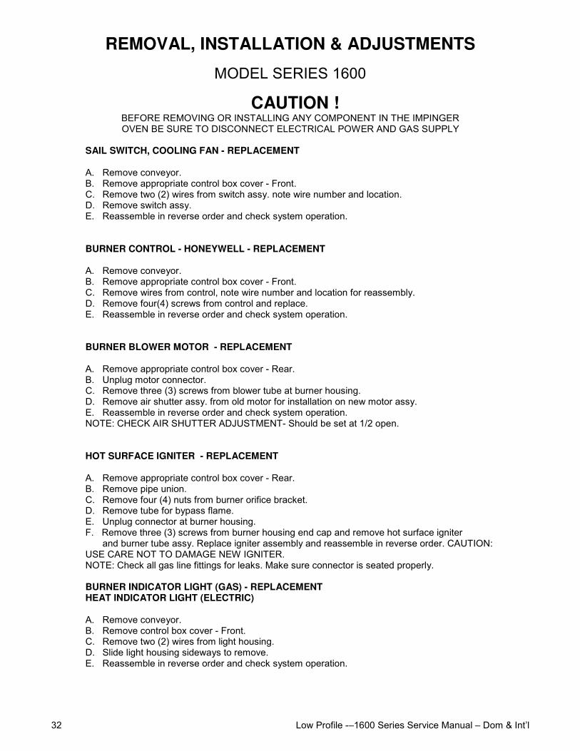
REMOVAL, INSTALLATION & ADJUSTMENTS
MODEL SERIES 1600
CAUTION !BEFORE REMOVING OR INSTALLING ANY COMPONENT IN THE IMPINGEROVEN BE SURE TO DISCONNECT ELECTRICAL POWER AND GAS SUPPLY
SAIL SWITCH, COOLING FAN - REPLACEMENT
A. Remove conveyor.B. Remove appropriate control box cover - Front.C. Remove two (2) wires from switch assy. note wire number and location.D. Remove switch assy.E. Reassemble in reverse order and check system operation.
BURNER CONTROL - HONEYWELL - REPLACEMENT
A. Remove conveyor.B. Remove appropriate control box cover - Front.C. Remove wires from control, note wire number and location for reassembly.D. Remove four(4) screws from control and replace.E. Reassemble in reverse order and check system operation.
BURNER BLOWER MOTOR - REPLACEMENT
A. Remove appropriate control box cover - Rear.B. Unplug motor connector.C. Remove three (3) screws from blower tube at burner housing.D. Remove air shutter assy. from old motor for installation on new motor assy.E. Reassemble in reverse order and check system operation.NOTE: CHECK AIR SHUTTER ADJUSTMENT- Should be set at 1/2 open.
HOT SURFACE IGNITER - REPLACEMENT
A. Remove appropriate control box cover - Rear.B. Remove pipe union.C. Remove four (4) nuts from burner orifice bracket.D. Remove tube for bypass flame.E. Unplug connector at burner housing.F. Remove three (3) screws from burner housing end cap and remove hot surface igniter
and burner tube assy. Replace igniter assembly and reassemble in reverse order. CAUTION:USE CARE NOT TO DAMAGE NEW IGNITER.NOTE: Check all gas line fittings for leaks. Make sure connector is seated properly.
BURNER INDICATOR LIGHT (GAS) - REPLACEMENTHEAT INDICATOR LIGHT (ELECTRIC)
A. Remove conveyor.B. Remove control box cover - Front.C. Remove two (2) wires from light housing.D. Slide light housing sideways to remove.E. Reassemble in reverse order and check system operation.
Low Profile -–1600 Series Service Manual – Dom & Int’l 33
CONVEYOR CONTROL POTENTIOMETER (50K OHM) - REPLACEMENT
A. Remove conveyor.B. Remove control box cover - Front.C. Loosen two (2) allen screws and remove knob by sliding off shaft.D. Remove shaft lock from potentiometer shaft and push out.E. Unplug wire connector from conveyor control board.F. Reassemble in reverse order and check system operation.NOTE: Install the shaft lock on the speed pot shaft so the threads go on first. THIS IS A TIGHTFITTING COLLAR DO NOT DRILL OUT THE HOLE. Slide the collar down the shaft and screw it ontothe mounting threads. Install the knob on the shaft and tighten the set screws. Before re-installing thecontrol box cover, check the operation of the speed pot through its full range to insure that the shaftlock doesn't come loose.G. Recalibrate conveyor control board.
20 MINUTE TIMER (COOL DOWN) - REPLACEMENT
A. Remove conveyor.B. Remove control box cover - Front.C. Remove four (4) wires, note wire numbers and location for reinstallation.D. Remove one (1) hold down screw and replace timer.E. Reassemble in reverse order and check system operation.
CONVEYOR CONTROL BOARD - REPLACEMENTAND CALIBRATION
A. Remove conveyor.B. Remove control box cover - Front.C. Remove three (3) screws from control assembly.D. Disconnect wiring (Push on connectors) from control board.
NOTE: Proper location of connectors for reinstallation.E. Reassemble in reverse order and check system operation.F. Recalibrate conveyor control board.
1. With power off, the five (5) dip switches located on the conveyor control(see drawing, next page) should be set as listed.
DIP SWITCHES
CONTROL 1 2 3 4 5SWITCH POSITION OFF OFF ON OFF OFF
2. With power off, the ten (10) dip switches located on rear of Time/Temp Display(see drawing on page 38) should be set (See Below)
NOTE: For time/temp displays using a thermistor probe (2 yellow wires in terminals 9 and 10, set dipswitches as follows.
DISPLAY 1 2 3 4 5 6 7 8 9 10SWITCH POSITION OFF * * ON OFF OFF ON ON OFF ON
*SWITCH 2 - OFF FOR 60HZ, ON FOR 50 HZ SWITCH 3 - OFF FOR °F, ON FOR ° C
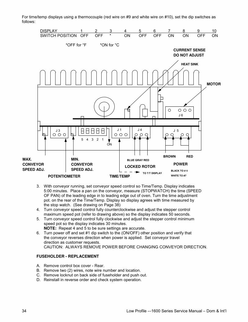
Low Profile -–1600 Series Service Manual – Dom & Int’l34
For time/temp displays using a thermocouple (red wire on #9 and white wire on #10), set the dip switches asfollows:
DISPLAY 1 2 3 4 5 6 7 8 9 10SWITCH POSITION OFF OFF * ON OFF OFF ON ON OFF ON
*OFF for °F *ON for °C
J 6
J 3 J 5J 4J 1
MOTOR
CURRENT SENSE DO NOT ADJUST
MAX. CONVEYOR SPEED ADJ.
POTENTIOMETER
MIN. CONVEYOR SPEED ADJ.
TIME/TEMP
BLUE GRAY RED
LOCKED ROTOR
REDBROWN
POWER
ON
HEAT SINK
TO T/T DISPLAYBLACK TO # 4
WHITE TO #7
5 4 3 2 1
3. With conveyor running, set conveyor speed control so Time/Temp. Display indicates5:00 minutes. Place a pan on the conveyor, measure (STOPWATCH) the time (SPEEDOF PAN) of the leading edge in to leading edge out of oven. Turn the time adjustmentpot. on the rear of the Time/Temp. Display so display agrees with time measured bythe stop watch. (See drawing on Page 38)
4. Turn conveyor speed control fully counterclockwise and adjust the stepper controlmaximum speed pot (refer to drawing above) so the display indicates 50 seconds.
5. Turn conveyor speed control fully clockwise and adjust the stepper control minimumspeed pot so the display indicates 30 minutes.NOTE: Repeat 4 and 5 to be sure settings are accurate.
6. Turn power off and set #1 dip switch to the (ON/OFF) other position and verify thatthe conveyor reverses direction when power is applied. Set conveyor traveldirection as customer requests.CAUTION: ALWAYS REMOVE POWER BEFORE CHANGING CONVEYOR DIRECTION.
FUSEHOLDER - REPLACEMENT
A. Remove control box cover - Rear.B. Remove two (2) wires, note wire number and location.C. Remove locknut on back side of fuseholder and push out.D. Reinstall in reverse order and check system operation.
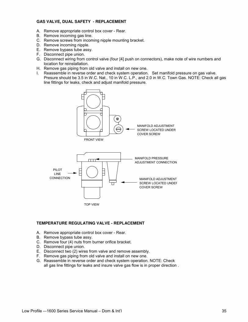
Low Profile -–1600 Series Service Manual – Dom & Int’l 35
GAS VALVE, DUAL SAFETY - REPLACEMENT
A. Remove appropriate control box cover - Rear.B. Remove incoming gas line.C. Remove screws from incoming nipple mounting bracket.D. Remove incoming nipple.E. Remove bypass tube assy.F. Disconnect pipe union.G. Disconnect wiring from control valve (four [4] push on connectors), make note of wire numbers and
location for reinstallation.H. Remove gas piping from old valve and install on new one.I. Reassemble in reverse order and check system operation. Set manifold pressure on gas valve.
Presure should be 3.5 in W.C. Nat., 10 in W.C. L.P., and 2.0 in W.C. Town Gas. NOTE: Check all gasline fittings for leaks, check and adjust manifold pressure.
FRONT VIEW
MANIFOLD ADJUSTMENT SCREW LOCATED UNDER COVER SCREW
TOP VIEW
PILOT LINE CONNECTION
MANIFOLD PRESSURE ADJUSTMENT CONNECTION
MANIFOLD ADJUSTMENT SCREW LOCATED UNDER COVER SCREW
TEMPERATURE REGULATING VALVE - REPLACEMENT
A. Remove appropriate control box cover - Rear.B. Remove bypass tube assy.C. Remove four (4) nuts from burner orifice bracket.D. Disconnect pipe union.E. Disconnect two (2) wires from valve and remove assembly.F. Remove gas piping from old valve and install on new one.G. Reassemble in reverse order and check system operation. NOTE: Check
all gas line fittings for leaks and insure valve gas flow is in proper direction .
Low Profile -–1600 Series Service Manual – Dom & Int’l36
MAIN ORIFICE - REPLACEMENTA. Remove appropriate control box cover - Rear.B. Remove bypass tube assembly.C. Remove four (4) nuts from burner orifice bracket.D. Disconnect pipe union.E. Remove assembly and replace main orifice.F. Reassemble in reverse order and check system operation.
NOTE: Check all gas line fittings for leaks.
TEMPERATURE CONTROL POTENTIOMETER - REPLACEMENT
A. Remove conveyor.B. Remove control box cover - Front.C. Loosen screw and slide knob off potentiometer shaft.D. Remove locknut and push out.E. Remove three (3) wires from electronic temperature control,
note wire color and location for reinstallation.F. Reassemble in reverse order and check system operation.
ON-OFF SWITCH (POWER/CONVEYOR) - REPLACEMENT
A. Remove conveyor.B. Remove control box cover - Front.C. Depress spring clips on side of switch and push out.D. Remove wires from back of switch, note wire number and location.E. Reassemble in reverse order and check system operation.
NOTE: Make sure switch housing is fully seated in control box housing.
DUAL TIME/TEMPERATURE DISPLAY - REPLACEMENT
A. Remove conveyor.B. Remove control box cover - Front.C. Remove wires from terminal strips on back of assembly (5 wires on top
7 wires on bottom), note wire location for reinstallation.D. Remove two (2) screws from display case and remove display.E. Reassemble in reverse order. (Make sure all wires are properly seated
and secure in terminal strip.) Check system operation and calibrate(Insure that dip switches are properly set.)
F. Apply power to unit and perform the following checks: Check for color andintensity match on displays and colons. Observe for display stability
G. (NOTE: At temperature below 150°F "LLL" should be illuminated on the temperaturedisplay section). Adjust the conveyor speed control knob to effect a largechange in motor speed and observe display response. (NOTE: Display updateswill lag the induced change by approx. 3 seconds.)
CALIBRATE TEMPERATURE
A. (See Page 37 for connection of Temperature Sensor.) Set Temp. Control to 500°F.Allow temperature to stabilize.
B. "Fine Tune" temperature setting to achieve measured temperature swings from497°F to 503°F. When actual temperature falls between 497°F and 503°F,the display must show 500°F.
C. Adjust temperature calibration pot on Time/Temp Display to achieve a display reading of 500°F (260°C).NOTE: D, E, and F are for displays with thermistor probe only.
D. Reset the temperature control to maximum and allow temperature to stabilize.E. Observe displayed number and compare to actual monitored temperature; if
displayed temperature is within 5°F (5°C) of actual, calibration is complete.F. If displayed temperature is in error by 10°F (10°C) or more then set the high
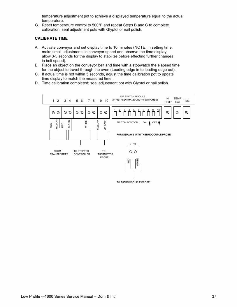
Low Profile -–1600 Series Service Manual – Dom & Int’l 37
temperature adjustment pot to achieve a displayed temperature equal to the actualtemperature.
G. Reset temperature control to 500°F and repeat Steps B anc C to completecalibration; seal adjustment pots with Glyptol or nail polish.
CALIBRATE TIME
A. Activate conveyor and set display time to 10 minutes (NOTE: In setting time,make small adjustments in conveyor speed and observe the time display;allow 3-5 seconds for the display to stabilize before effecting further changesin belt speed).
B. Place an object on the conveyor belt and time with a stopwatch the elapsed timefor the object to travel through the oven (Leading edge in to leading edge out).
C. If actual time is not within 5 seconds, adjust the time calibration pot to updatetime display to match the measured time.
D. Time calibration completed; seal adjustment pot with Glyptol or nail polish.
1 2 3 4 5 6 7 8 9 10
1 2 3 4 5 6 7 8 9 10 HI TEMP
TEMP CAL TIME
FROM TRANSFORMER
TO THERMISTOR PROBE
RED RED
YELL
OW
BLAC
K
WH
ITE
YELL
OW
YELL
OW
DIP SWITCH MODULE (TYPE I AND II HAVE ONLY 6 SWITCHES)
SWITCH POSITION ON OFF
TO STEPPER CONTROLLER
FOR DISPLAYS WITH THERMOCOUPLE PROBE
9 10
TO THERMOCOUPLE PROBE
RED
WH
ITE
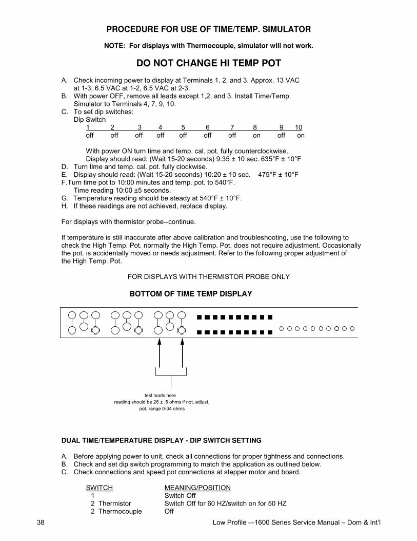
Low Profile -–1600 Series Service Manual – Dom & Int’l38
PROCEDURE FOR USE OF TIME/TEMP. SIMULATOR
NOTE: For displays with Thermocouple, simulator will not work.
DO NOT CHANGE Hl TEMP POT
A. Check incoming power to display at Terminals 1, 2, and 3. Approx. 13 VACat 1-3, 6.5 VAC at 1-2, 6.5 VAC at 2-3.
B. With power OFF, remove all leads except 1,2, and 3. Install Time/Temp.Simulator to Terminals 4, 7, 9, 10.
C. To set dip switches:Dip Switch
1 2 3 4 5 6 7 8 9 10off off off off off off off on off on
With power ON turn time and temp. cal. pot. fully counterclockwise.Display should read: (Wait 15-20 seconds) 9:35 ± 10 sec. 635°F ± 10°F
D. Turn time and temp. cal. pot. fully clockwise.E. Display should read: (Wait 15-20 seconds) 10:20 ± 10 sec. 475°F ± 10°FF. Turn time pot to 10:00 minutes and temp. pot. to 540°F.
Time reading 10:00 ±5 seconds.G. Temperature reading should be steady at 540°F ± 10°F.H. If these readings are not achieved, replace display.
For displays with thermistor probe--continue.
If temperature is still inaccurate after above calibration and troubleshooting, use the following tocheck the High Temp. Pot. normally the High Temp. Pot. does not require adjustment. Occasionallythe pot. is accidentally moved or needs adjustment. Refer to the following proper adjustment ofthe High Temp. Pot.
FOR DISPLAYS WITH THERMISTOR PROBE ONLY
test leads herereading should be 26 ± .5 ohms if not, adjust. pot. range 0-34 ohms
BOTTOM OF TIME TEMP DISPLAY
DUAL TIME/TEMPERATURE DISPLAY - DIP SWITCH SETTING
A. Before applying power to unit, check all connections for proper tightness and connections.B. Check and set dip switch programming to match the application as outlined below.C. Check connections and speed pot connections at stepper motor and board.
SWITCH MEANING/POSITION1 Switch Off
2 Thermistor Switch Off for 60 HZ/switch on for 50 HZ2 Thermocouple Off
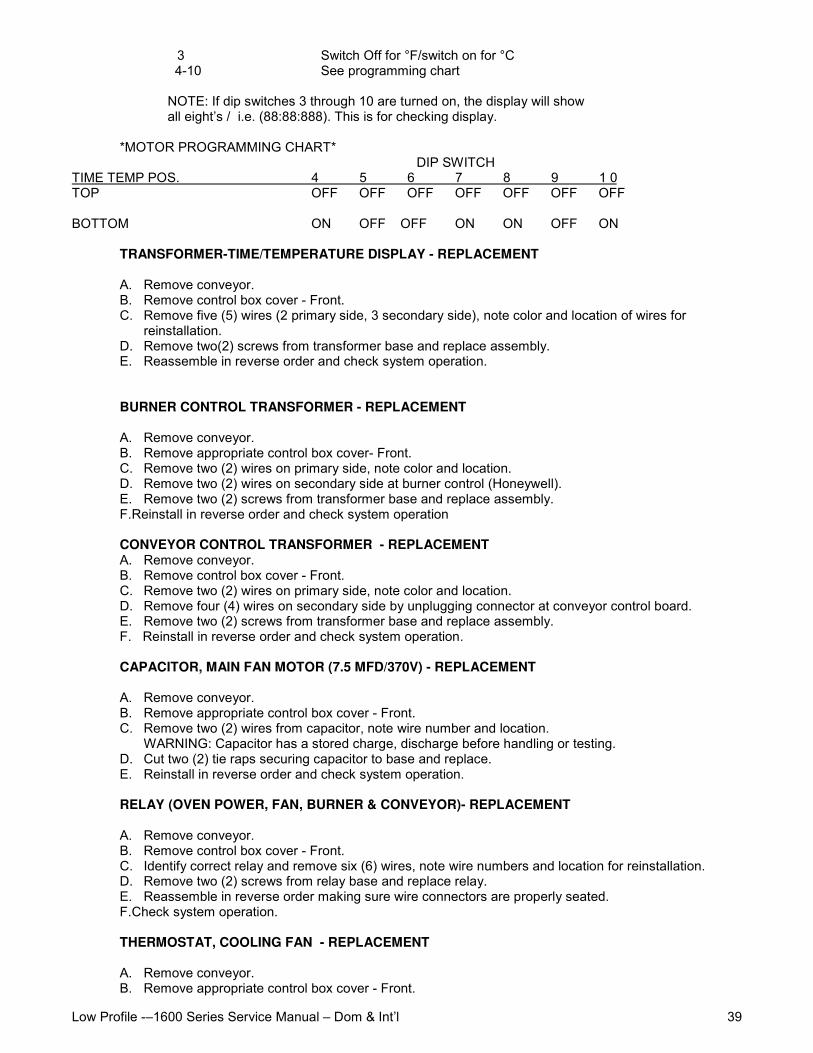
Low Profile -–1600 Series Service Manual – Dom & Int’l 39
3 Switch Off for °F/switch on for °C 4-10 See programming chart
NOTE: If dip switches 3 through 10 are turned on, the display will showall eight’s / i.e. (88:88:888). This is for checking display.
*MOTOR PROGRAMMING CHART* DIP SWITCHTIME TEMP POS. 4 5 6 7 8 9 1 0TOP OFF OFF OFF OFF OFF OFF OFF
BOTTOM ON OFF OFF ON ON OFF ON
TRANSFORMER-TIME/TEMPERATURE DISPLAY - REPLACEMENT
A. Remove conveyor.B. Remove control box cover - Front.C. Remove five (5) wires (2 primary side, 3 secondary side), note color and location of wires for
reinstallation.D. Remove two(2) screws from transformer base and replace assembly.E. Reassemble in reverse order and check system operation.
BURNER CONTROL TRANSFORMER - REPLACEMENT
A. Remove conveyor.B. Remove appropriate control box cover- Front.C. Remove two (2) wires on primary side, note color and location.D. Remove two (2) wires on secondary side at burner control (Honeywell).E. Remove two (2) screws from transformer base and replace assembly.F. Reinstall in reverse order and check system operation
CONVEYOR CONTROL TRANSFORMER - REPLACEMENTA. Remove conveyor.B. Remove control box cover - Front.C. Remove two (2) wires on primary side, note color and location.D. Remove four (4) wires on secondary side by unplugging connector at conveyor control board.E. Remove two (2) screws from transformer base and replace assembly.F. Reinstall in reverse order and check system operation.
CAPACITOR, MAIN FAN MOTOR (7.5 MFD/370V) - REPLACEMENT
A. Remove conveyor.B. Remove appropriate control box cover - Front.C. Remove two (2) wires from capacitor, note wire number and location.
WARNING: Capacitor has a stored charge, discharge before handling or testing.D. Cut two (2) tie raps securing capacitor to base and replace.E. Reinstall in reverse order and check system operation.
RELAY (OVEN POWER, FAN, BURNER & CONVEYOR)- REPLACEMENT
A. Remove conveyor.B. Remove control box cover - Front.C. Identify correct relay and remove six (6) wires, note wire numbers and location for reinstallation.D. Remove two (2) screws from relay base and replace relay.E. Reassemble in reverse order making sure wire connectors are properly seated.F. Check system operation.
THERMOSTAT, COOLING FAN - REPLACEMENT
A. Remove conveyor.B. Remove appropriate control box cover - Front.
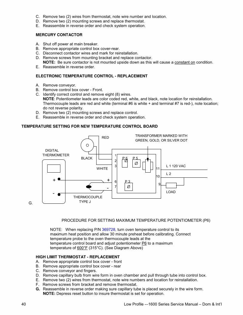
Low Profile -–1600 Series Service Manual – Dom & Int’l40
C. Remove two (2) wires from thermostat, note wire number and location.D. Remove two (2) mounting screws and replace thermostat.E. Reassemble in reverse order and check system operation.
MERCURY CONTACTOR
A. Shut off power at main breaker.B. Remove appropriate control box cover-rear.C. Disconnect contactor wires and mark for reinstallation.D. Remove screws from mounting bracket and replace contactor.
NOTE: Be sure contactor is not mounted upside down as this will cause a constant on condition.E. Reassemble in reverse order.
ELECTRONIC TEMPERATURE CONTROL - REPLACEMENT
A. Remove conveyor.B. Remove control box cover - Front.C. Identify correct control and remove eight (8) wires.
NOTE: Potentiometer leads are color coded red, white, and black, note location for reinstallation.Thermocouple leads are red and white (terminal #6 is white + and terminal #7 is red-), note location;do not reverse polarity.
D. Remove two (2) mounting screws and replace control.E. Reassemble in reverse order and check system operation.
TEMPERATURE SETTING FOR NEW TEMPERATURE CONTROL BOARD
G.
1
23
67
P 3
P 5P 6
11
10
9
L 1 120 VAC
L 2
LOAD
RED
BLACK
WHITE
DIGITAL THERMOMETER
+-
+
-THERMOCOUPLE TYPE J
TRANSFORMER MARKED WITH GREEN, GOLD, OR SILVER DOT
PROCEDURE FOR SETTING MAXIMUM TEMPERATURE POTENTIOMETER (P6)
NOTE: When replacing P/N 369728, turn oven temperature control to itsmaximum heat position and allow 30 minute preheat before calibrating. Connecttemperature probe to the oven thermocouple leads at thetemperature control board and adjust potentiometer P6 to a maximumtemperature of 600°F (315°C). (See Diagram Above)
HIGH LIMIT THERMOSTAT - REPLACEMENTA. Remove appropriate control box cover - frontB. Remove appropriate control box cover - rearC. Remove conveyor and fingers.D. Remove capillary bulb from wire form in oven chamber and pull through tube into control box.E. Remove two (2) wires from thermostat, note wire numbers and location for reinstallation.F. Remove screws from bracket and remove thermostat.G. Reassemble in reverse order making sure capillary tube is placed securely in the wire form.
NOTE: Depress reset button to insure thermostat is set for operation.
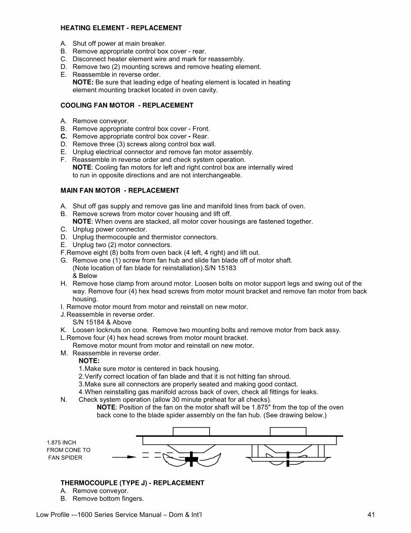
Low Profile -–1600 Series Service Manual – Dom & Int’l 41
HEATING ELEMENT - REPLACEMENT
A. Shut off power at main breaker.B. Remove appropriate control box cover - rear.C. Disconnect heater element wire and mark for reassembly.D. Remove two (2) mounting screws and remove heating element.E. Reassemble in reverse order.
NOTE: Be sure that leading edge of heating element is located in heatingelement mounting bracket located in oven cavity.
COOLING FAN MOTOR - REPLACEMENT
A. Remove conveyor.B. Remove appropriate control box cover - Front.C. Remove appropriate control box cover - Rear.D. Remove three (3) screws along control box wall.E. Unplug electrical connector and remove fan motor assembly.F. Reassemble in reverse order and check system operation.
NOTE: Cooling fan motors for left and right control box are internally wiredto run in opposite directions and are not interchangeable.
MAIN FAN MOTOR - REPLACEMENT
A. Shut off gas supply and remove gas line and manifold lines from back of oven.B. Remove screws from motor cover housing and lift off.
NOTE: When ovens are stacked, all motor cover housings are fastened together.C. Unplug power connector.D. Unplug thermocouple and thermistor connectors.E. Unplug two (2) motor connectors.F. Remove eight (8) bolts from oven back (4 left, 4 right) and lift out.G. Remove one (1) screw from fan hub and slide fan blade off of motor shaft.
(Note location of fan blade for reinstallation).S/N 15183& Below
H. Remove hose clamp from around motor. Loosen bolts on motor support legs and swing out of theway. Remove four (4) hex head screws from motor mount bracket and remove fan motor from backhousing.
I. Remove motor mount from motor and reinstall on new motor.J. Reassemble in reverse order.
S/N 15184 & AboveK. Loosen locknuts on cone. Remove two mounting bolts and remove motor from back assy.L. Remove four (4) hex head screws from motor mount bracket.
Remove motor mount from motor and reinstall on new motor.M. Reassemble in reverse order.
NOTE:1. Make sure motor is centered in back housing.2. Verify correct location of fan blade and that it is not hitting fan shroud.3. Make sure all connectors are properly seated and making good contact.4. When reinstalling gas manifold across back of oven, check all fittings for leaks.
N. Check system operation (allow 30 minute preheat for all checks).NOTE: Position of the fan on the motor shaft will be 1.875" from the top of the ovenback cone to the blade spider assembly on the fan hub. (See drawing below.)
1.875 INCH FROM CONE TO FAN SPIDER
THERMOCOUPLE (TYPE J) - REPLACEMENTA. Remove conveyor.B. Remove bottom fingers.
Low Profile -–1600 Series Service Manual – Dom & Int’l42
C. Remove appropriate control box covers (Front & Rear).NOTE: For ovens serial number L21545 and above, the oven back must be removed to replace thethermocouple.
D. Remove thermocouple from wire form in oven chamber and remove from chamber. NOTE: R. H.Thermocouple (viewed from front) is connected directly to the temperature control board, remove two(2) wires, make note of wire colors (terminal #6 is White + and terminal #7 is Red-) and location forreinstallation. When changing L.H. Thermocouple (viewed from front), the back motor cover mustalso be removed to gain access to the thermocouple connector plug.
E. Reassemble in reverse order making sure bulb is placed securely in the wireform in the oven chamber.
F. Check system operation, recalibrate as needed. NOTE: The R.H. and L.H. Thermocouples havedifferent connectors on the wire ends and must be ordered accordingly.
INFORMATION:
When two wires composed of dissimilar metals are joined together and one of the ends is heated, acontinuous current flow is generated. We use an iron constant (Type J) thermocouple. The iron wireincreases the number of dissimilar junctions in the circuit.
It is possible to check a thermocouple with a properly calibrated D.C. millivolt meter. At 32°F, the millivoltreading should be 0.00. This can be checked by inserting thethermocouple into an ice bath.
The millivolt reading at 72°F should be 1.134.
When using the following chart, the temperature at the terminal connections must be noted. Thistemperature is call the Junction Temperature.
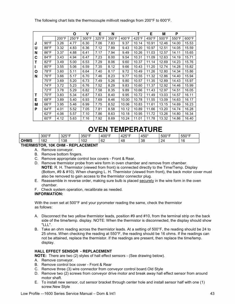
Low Profile -–1600 Series Service Manual – Dom & Int’l 43
The following chart lists the thermocouple millivolt readings from 200°F to 600°F.
O V E N T E M P200°F 250°F 300°F 325°F 350°F 400°F 425°F 450°F 500°F 550°F 600°F
J 90°F 3.26 4.77 6.30 7.06 7.83 9.37 10.14 10.91 12.46 14.00 15.53U 88°F 3.32 4.83 6.36 7.12 7.89 9.43 10.20 10.97 12.51 14.05 15.59N 86°F 3.37 4.88 6.41 7.17 7.94 9.49 10.26 11.03 12.57 14.11 15.65C 84°F 3.43 4.94 6.47 7.23 8.00 9.54 10.31 11.09 12.63 14.19 15.71T 82°F 3.49 5.00 6.53 7.29 8.06 9.60 10.37 11.14 12.69 14.23 15.76I 80°F 3.55 5.06 6.59 7.35 8.12 9.66 10.43 11.20 12.74 14.28 15.82O 78°F 3.60 5.11 6.64 7.40 8.17 9.72 10.49 11.26 12.80 14.34 15.86N 76°F 3.66 5.17 6.70 7.46 8.23 9.77 10.55 11.32 12.86 14.40 15.94
75°F 3.69 5.20 6.73 7.49 5.26 9.80 10.57 11.35 12.89 14.43 15.9774°F 3.72 5.23 6.76 7.52 8.29 9.83 10.60 11.37 12.92 14.46 15.9972°F 3.78 5.29 6.82 7.58 8.35 9.89 10.66 11.43 12.97 14.51 16.05
T 70°F 3.83 5.34 6.87 7.63 8.40 9.95 10.72 11.49 13.03 14.57 16.11E 68°F 3.89 5.40 6.93 7.69 8.46 10.00 10.78 11.55 13.09 14.63 16.17M 66°F 3.95 5.46 6.99 7.75 8.52 10.06 10.83 11.61 13.15 14.69 16.23P 64°F 4.01 5.52 7.05 7.81 8.58 10.12 10.89 11.66 13.20 14.74 16.28
62°F 4.06 5.57 7.10 7.86 8.63 10.18 10.95 11.72 13.26 14.80 16.3460°F 4.12 5.63 7.16 7.92 8.69 10.24 11.01 11.78 13.32 14.86 16.40
OVEN TEMPERATURE300°F 325°F 350°F 400°F 425°F 450° 500°F 550°F
OHMS 182 138 102 62 48 38 24 16THERMISTOR, 10K OHM - REPLACEMENT
A. Remove conveyor.B. Remove bottom fingers.C. Remove appropriate control box covers - Front & Rear.D. Remove thermistor probe from wire form in oven chamber and remove from chamber.
NOTE: R. H. Thermistor (viewed from front) is connected directly to the Time/Temp. Display(Bottom, #9 & #10). When changing L. H. Thermistor (viewed from front), the back motor cover mustalso be removed to gain access to the thermistor connector plug.
E. Reassemble in reverse order, making sure bulb is placed securely in the wire form in the ovenchamber.
F. Check system operation, recalibrate as needed.INFORMATION:
With the oven set at 500°F and your pyrometer reading the same, check the thermistoras follows:
A. Disconnect the two yellow thermistor leads, position #9 and #10, from the terminal strip on the backside of the time/temp. display. NOTE: When the thermistor is disconnected, the display should show"LLL".
B. Take an ohm reading across the thermistor leads. At a setting of 500°F, the reading should be 24 to25 ohms. When checking the reading at 550°F, the reading should be 16 ohms. If the readings cannot be attained, replace the thermistor. If the readings are present, then replace the time/temp.display.
HALL EFFECT SENSOR - REPLACEMENTNOTE: There are two (2) styles of hall effect sensors - (See drawing below).A. Remove conveyor.B. Remove control box cover - Front & RearC. Remove three (3) wire connector from conveyor control board.Old StyleD. Remove two (2) screws from conveyor drive motor and break away hall effect sensor from around
motor shaft.E. To install new sensor, cut sensor bracket through center hole and install sensor half with one (1)
screw.New Style
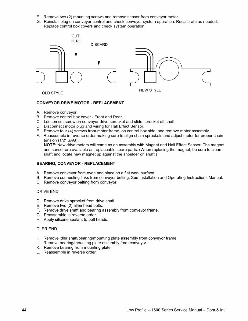
Low Profile -–1600 Series Service Manual – Dom & Int’l44
F. Remove two (2) mounting screws and remove sensor from conveyor motor.G. Reinstall plug on conveyor control and check conveyor system operation. Recalibrate as needed.H. Replace control box covers and check system operation.
CUT HERE
DISCARD
OLD STYLENEW STYLE
CONVEYOR DRIVE MOTOR - REPLACEMENT
A. Remove conveyor.B. Remove control box cover - Front and Rear.C. Loosen set screw on conveyor drive sprocket and slide sprocket off shaft.D. Disconnect motor plug and wiring for Hall Effect Sensor.E. Remove four (4) screws from motor frame, on control box side, and remove motor assembly.F. Reassemble in reverse order making sure to align chain sprockets and adjust motor for proper chain
tension (1/2" SAG).NOTE: New drive motors will come as an assembly with Magnet and Hall Effect Sensor. The magnetand sensor are available as replaceable spare parts. (When replacing the magnet, be sure to cleanshaft and locate new magnet up against the shoulder on shaft.)
BEARING, CONVEYOR - REPLACEMENT
A. Remove conveyor from oven and place on a flat work surface.B. Remove connecting links from conveyor belting. See Installation and Operating Instructions Manual.C. Remove conveyor belting from conveyor.
DRIVE END
D. Remove drive sprocket from drive shaft.E. Remove two (2) allen head bolts.F. Remove drive shaft and bearing assembly from conveyor frame.G. Reassemble in reverse order.H. Apply silicone sealant to bolt heads.
IDLER END
I. Remove idler shaft/bearing/mounting plate assembly from conveyor frame.J. Remove bearing/mounting plate assembly from conveyor.K. Remove bearing from mounting plate.L. Reassemble in reverse order.
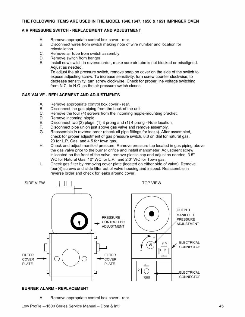
Low Profile -–1600 Series Service Manual – Dom & Int’l 45
THE FOLLOWING ITEMS ARE USED IN THE MODEL 1646,1647, 1650 & 1651 IMPINGER OVEN
AIR PRESSURE SWITCH - REPLACEMENT AND ADJUSTMENT
A. Remove appropriate control box cover - rear.B. Disconnect wires from switch making note of wire number and location for
reinstallation.C. Remove air tube from switch assembly.D. Remove switch from hanger.E. Install new switch in reverse order, make sure air tube is not blocked or misaligned.
Adjust as needed.To adjust the air pressure switch, remove snap on cover on the side of the switch toexpose adjusting screw. To increase sensitivity, turn screw counter clockwise; todecrease sensitivity, turn screw clockwise. Check for proper line voltage switchingfrom N.C. to N.O. as the air pressure switch closes.
GAS VALVE - REPLACEMENT AND ADJUSTMENTS
A. Remove appropriate control box cover - rear.B. Disconnect the gas piping from the back of the unit.C. Remove the four (4) screws from the incoming nipple-mounting bracket.D. Remove incoming nipple.E. Disconnect two (2) plugs, (1) 3 prong and (1) 4 prong - Note location.F. Disconnect pipe union just above gas valve and remove assembly.G. Reassemble in reverse order (check all pipe fittings for leaks). After assembled,
check for proper adjustment of gas pressure switch, 8.8 on dial for natural gas,23 for L.P. Gas, and 4.5 for town gas.
H. Check and adjust manifold pressure. Remove pressure tap located in gas piping abovethe gas valve prior to the burner orifice and install manometer. Adjustment screwis located on the front of the valve, remove plastic cap and adjust as needed: 3.5"WC for Natural Gas, 10" WC for L.P., and 2.0" WC for Town gas.
I. Check gas filter by removing cover plate (located on either side of valve). Removefour(4) screws and slide filter out of valve housing and inspect. Reassemble inreverse order and check for leaks around cover.
+
- 1 2
gnd
3
3 2
gnd
FILTER COVER PLATE
FILTER COVER PLATE
PRESSURE CONTROLLER ADJUSTMENT
MANIFOLD PRESSURE ADJUSTMENT
OUTPUT
ELECTRICAL CONNECTOR
ELECTRICAL CONNECTOR
TOP VIEWSIDE VIEW
BURNER ALARM - REPLACEMENT
A. Remove appropriate control box cover - rear.
Low Profile -–1600 Series Service Manual – Dom & Int’l46
B. Remove two (2) wires from alarm, note wire numbers and location.C. Remove retainer cover from alarm and remove assembly from control box.D. Reassemble in reverse order and check operation.
SPARK GENERATOR - REPLACEMENT
A. Remove appropriate control box cover - rear.B. Remove two (2) wires for spark generator.C. Unplug connector on bottom of spark generator.D. Remove two (2) mounting screws and remove generator assembly.E. Reassemble in reverse order and check system operation.
IGNITION CONTROL - REPLACEMENT
A. Remove appropriate control box cover - rear.B. Remove front portion of relay by releasing tabs on side pulling straight out
(rocking motion).C. Remove wires from plug-in terminal strip, note wire numbers and location.D. Remove two(2) screws from mounting bracket and remove.E. Reassemble in reverse order. Check system operation.
IGNITER SENSOR ASSEMBLY - REPLACEMENT
A. Remove appropriate control box cover - rear.B. Remove gas valve assembly (See Gas Valve).C. Remove screws from burner tube and pull burner assembly out.D. Remove wire connectors from igniter sensor assembly.E. Remove screws from mounting bracket and remove assembly.F. Reassemble in reverse order and check system operation.NOTE: After installation, check all pipe fittings for leaks.

Low Profile -–1600 Series Service Manual – Dom & Int’l 47
This page intentionally left blank.
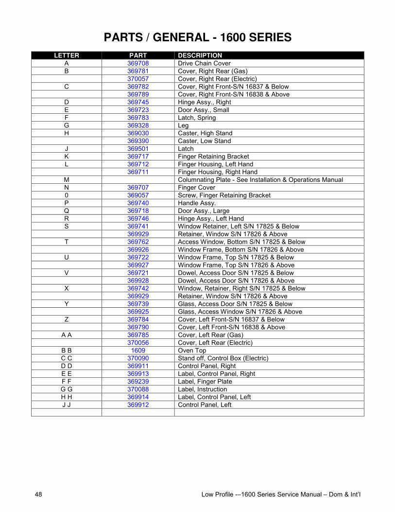
Low Profile -–1600 Series Service Manual – Dom & Int’l48
PARTS / GENERAL - 1600 SERIESLETTER PART DESCRIPTION
A 369708 Drive Chain CoverB 369781 Cover, Right Rear (Gas)
370057 Cover, Right Rear (Electric)C 369782 Cover, Right Front-S/N 16837 & Below
369789 Cover, Right Front-S/N 16838 & AboveD 369745 Hinge Assy., RightE 369723 Door Assy., SmallF 369783 Latch, SpringG 369328 LegH 369030 Caster, High Stand
369390 Caster, Low StandJ 369501 LatchK 369717 Finger Retaining BracketL 369712 Finger Housing, Left Hand
369711 Finger Housing, Right HandM Columnating Plate - See Installation & Operations ManualN 369707 Finger Cover0 369057 Screw, Finger Retaining BracketP 369740 Handle Assy.Q 369718 Door Assy., LargeR 369746 Hinge Assy., Left HandS 369741 Window Retainer, Left S/N 17825 & Below
369929 Retainer, Window S/N 17826 & AboveT 369762 Access Window, Bottom S/N 17825 & Below
369926 Window Frame, Bottom S/N 17826 & AboveU 369722 Window Frame, Top S/N 17825 & Below
369927 Window Frame, Top S/N 17826 & AboveV 369721 Dowel, Access Door S/N 17825 & Below
369928 Dowel, Access Door S/N 17826 & AboveX 369742 Window, Retainer, Right S/N 17825 & Below
369929 Retainer, Window S/N 17826 & AboveY 369739 Glass, Access Door S/N 17825 & Below
369925 Glass, Access Window S/N 17826 & AboveZ 369784 Cover, Left Front-S/N 16837 & Below
369790 Cover, Left Front-S/N 16838 & AboveA A 369785 Cover, Left Rear (Gas)
370056 Cover, Left Rear (Electric)B B 1609 Oven TopC C 370090 Stand off, Control Box (Electric)D D 369911 Control Panel, RightE E 369913 Label, Control Panel, RightF F 369239 Label, Finger PlateG G 370088 Label, InstructionH H 369914 Label, Control Panel, LeftJ J 369912 Control Panel, Left
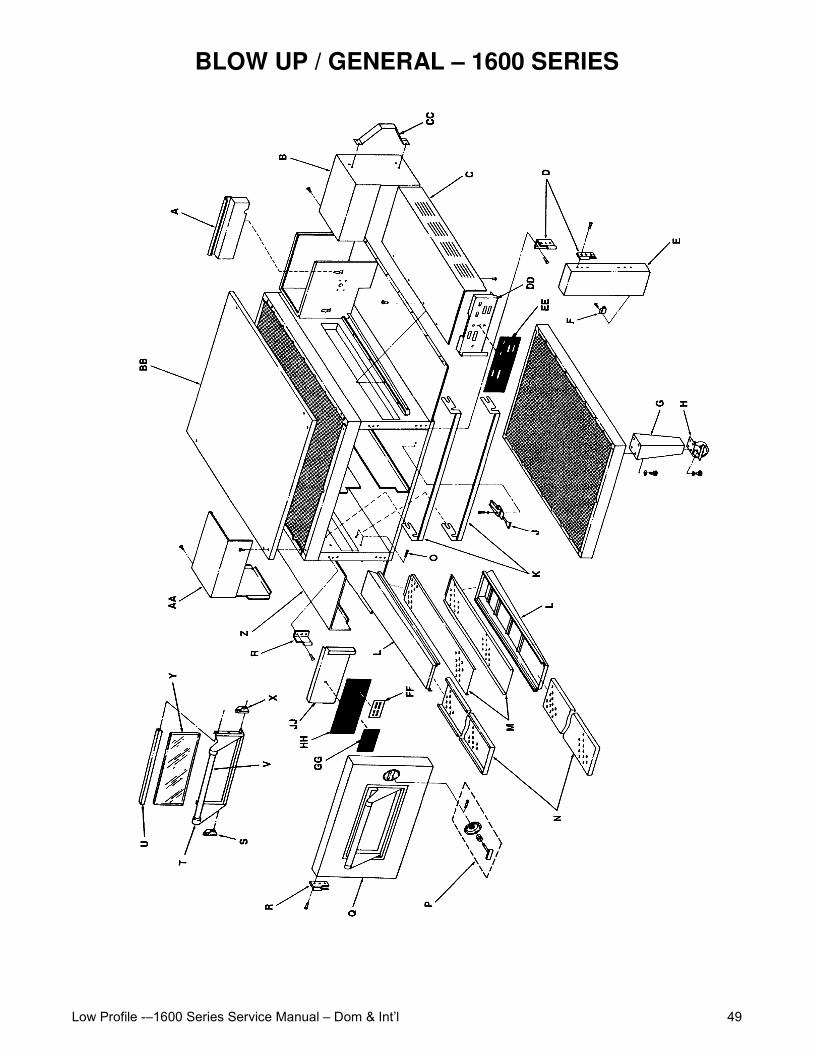
Low Profile -–1600 Series Service Manual – Dom & Int’l 49
BLOW UP / GENERAL – 1600 SERIES
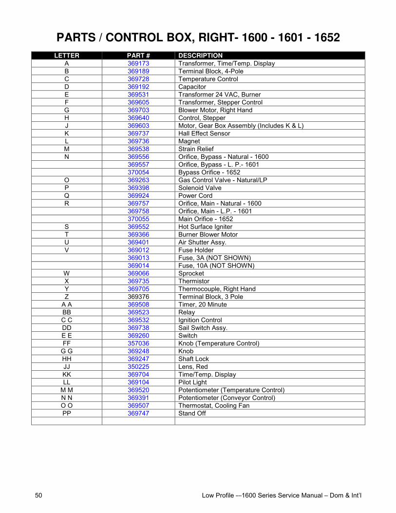
Low Profile -–1600 Series Service Manual – Dom & Int’l50
PARTS / CONTROL BOX, RIGHT- 1600 - 1601 - 1652LETTER PART # DESCRIPTION
A 369173 Transformer, Time/Temp. DisplayB 369189 Terminal Block, 4-PoleC 369728 Temperature ControlD 369192 CapacitorE 369531 Transformer 24 VAC, BurnerF 369605 Transformer, Stepper ControlG 369703 Blower Motor, Right HandH 369640 Control, StepperJ 369603 Motor, Gear Box Assembly (Includes K & L)K 369737 Hall Effect SensorL 369736 MagnetM 369538 Strain ReliefN 369556 Orifice, Bypass - Natural - 1600
369557 Orifice, Bypass - L. P.- 1601370054 Bypass Orifice - 1652
O 369263 Gas Control Valve - Natural/LPP 369398 Solenoid ValveQ 369924 Power CordR 369757 Orifice, Main - Natural - 1600
369758 Orifice, Main - L.P. - 1601370055 Main Orifice - 1652
S 369552 Hot Surface IgniterT 369366 Burner Blower MotorU 369401 Air Shutter Assy.V 369012 Fuse Holder
369013 Fuse, 3A (NOT SHOWN)369014 Fuse, 10A (NOT SHOWN)
W 369066 SprocketX 369735 ThermistorY 369705 Thermocouple, Right HandZ 369376 Terminal Block, 3 Pole
A A 369508 Timer, 20 MinuteBB 369523 RelayC C 369532 Ignition ControlDD 369738 Sail Switch Assy.E E 369260 SwitchFF 357036 Knob (Temperature Control)
G G 369248 KnobHH 369247 Shaft LockJJ 350225 Lens, RedKK 369704 Time/Temp. DisplayLL 369104 Pilot Light
M M 369520 Potentiometer (Temperature Control)N N 369391 Potentiometer (Conveyor Control)O O 369507 Thermostat, Cooling FanPP 369747 Stand Off
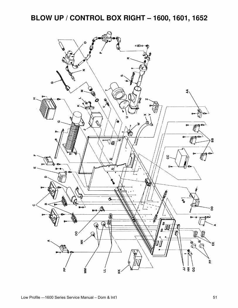
Low Profile -–1600 Series Service Manual – Dom & Int’l 51
BLOW UP / CONTROL BOX RIGHT – 1600, 1601, 1652
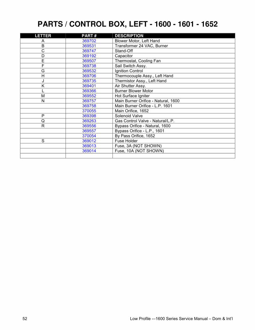
Low Profile -–1600 Series Service Manual – Dom & Int’l52
PARTS / CONTROL BOX, LEFT - 1600 - 1601 - 1652LETTER PART # DESCRIPTION
A 369702 Blower Motor, Left HandB 369531 Transformer 24 VAC, BurnerC 369747 Stand-OffD 369192 CapacitorE 369507 Thermostat, Cooling FanF 369738 Sail Switch Assy.G 369532 Ignition ControlH 369706 Thermocouple Assy., Left HandJ 369735 Thermistor Assy., Left HandK 369401 Air Shutter Assy.L 369366 Burner Blower MotorM 369552 Hot Surface IgniterN 369757 Main Burner Orifice - Natural, 1600
369758 Main Burner Orifice - L.P. 1601370055 Main Orifice, 1652
P 369398 Solenoid ValveQ 369263 Gas Control Valve - Natural/L.P.R 369556 Bypass Orifice - Natural, 1600
369557 Bypass Orifice - L.P., 1601370054 By Pass Orifice, 1652
S 369012 Fuse Holder369013 Fuse, 3A (NOT SHOWN)369014 Fuse, 10A (NOT SHOWN)
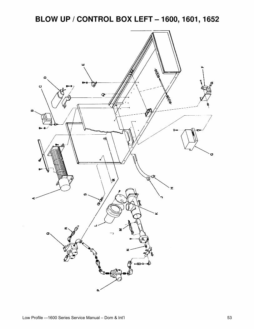
Low Profile -–1600 Series Service Manual – Dom & Int’l 53
BLOW UP / CONTROL BOX LEFT – 1600, 1601, 1652
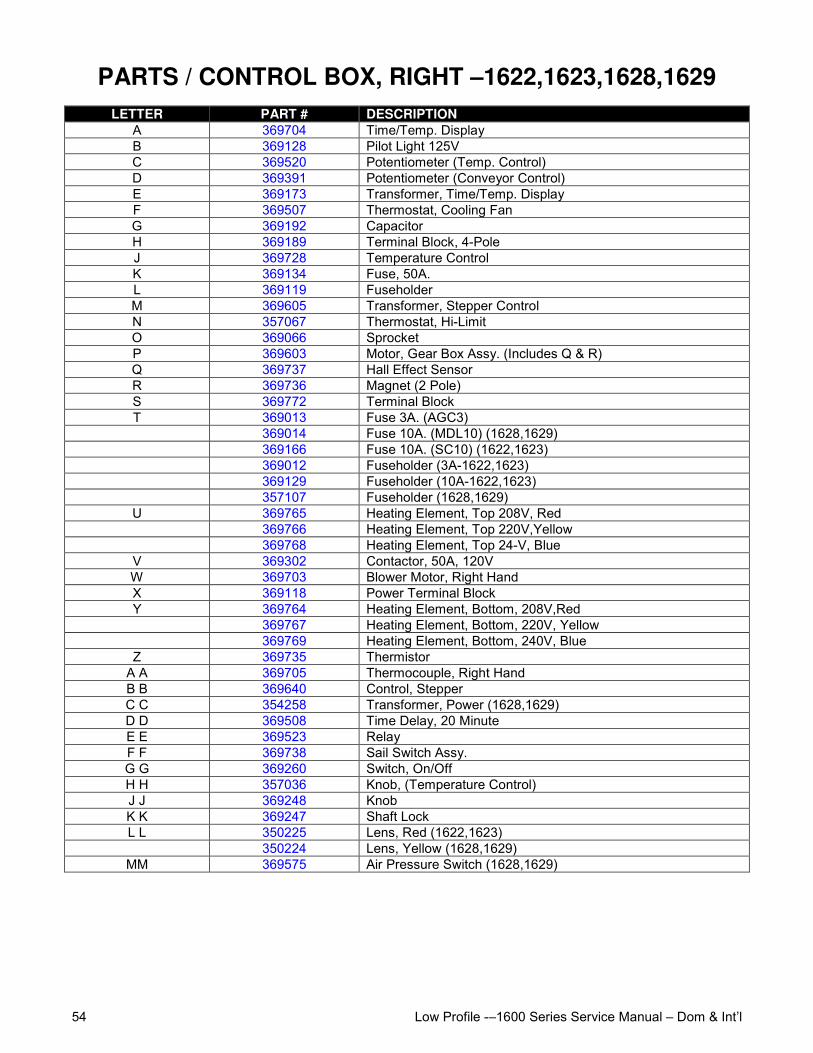
Low Profile -–1600 Series Service Manual – Dom & Int’l54
PARTS / CONTROL BOX, RIGHT –1622,1623,1628,1629LETTER PART # DESCRIPTION
A 369704 Time/Temp. DisplayB 369128 Pilot Light 125VC 369520 Potentiometer (Temp. Control)D 369391 Potentiometer (Conveyor Control)E 369173 Transformer, Time/Temp. DisplayF 369507 Thermostat, Cooling FanG 369192 CapacitorH 369189 Terminal Block, 4-PoleJ 369728 Temperature ControlK 369134 Fuse, 50A.L 369119 FuseholderM 369605 Transformer, Stepper ControlN 357067 Thermostat, Hi-LimitO 369066 SprocketP 369603 Motor, Gear Box Assy. (Includes Q & R)Q 369737 Hall Effect SensorR 369736 Magnet (2 Pole)S 369772 Terminal BlockT 369013 Fuse 3A. (AGC3)
369014 Fuse 10A. (MDL10) (1628,1629)369166 Fuse 10A. (SC10) (1622,1623)369012 Fuseholder (3A-1622,1623)369129 Fuseholder (10A-1622,1623)357107 Fuseholder (1628,1629)
U 369765 Heating Element, Top 208V, Red369766 Heating Element, Top 220V,Yellow369768 Heating Element, Top 24-V, Blue
V 369302 Contactor, 50A, 120VW 369703 Blower Motor, Right HandX 369118 Power Terminal BlockY 369764 Heating Element, Bottom, 208V,Red
369767 Heating Element, Bottom, 220V, Yellow369769 Heating Element, Bottom, 240V, Blue
Z 369735 ThermistorA A 369705 Thermocouple, Right HandB B 369640 Control, StepperC C 354258 Transformer, Power (1628,1629)D D 369508 Time Delay, 20 MinuteE E 369523 RelayF F 369738 Sail Switch Assy.G G 369260 Switch, On/OffH H 357036 Knob, (Temperature Control)J J 369248 KnobK K 369247 Shaft LockL L 350225 Lens, Red (1622,1623)
350224 Lens, Yellow (1628,1629)MM 369575 Air Pressure Switch (1628,1629)
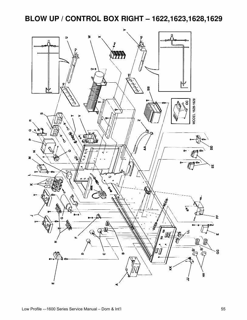
Low Profile -–1600 Series Service Manual – Dom & Int’l 55
BLOW UP / CONTROL BOX RIGHT – 1622,1623,1628,1629
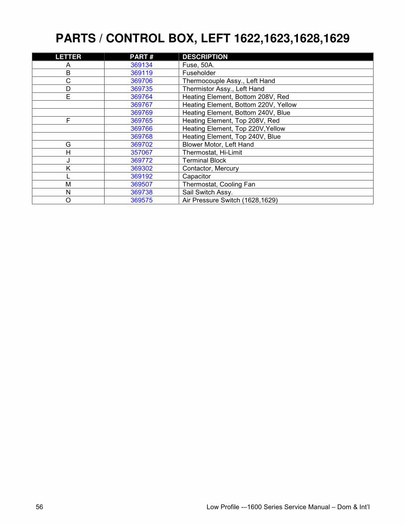
Low Profile -–1600 Series Service Manual – Dom & Int’l56
PARTS / CONTROL BOX, LEFT 1622,1623,1628,1629LETTER PART # DESCRIPTION
A 369134 Fuse, 50A.B 369119 FuseholderC 369706 Thermocouple Assy., Left HandD 369735 Thermistor Assy., Left HandE 369764 Heating Element, Bottom 208V, Red
369767 Heating Element, Bottom 220V, Yellow369769 Heating Element, Bottom 240V, Blue
F 369765 Heating Element, Top 208V, Red369766 Heating Element, Top 220V,Yellow369768 Heating Element, Top 240V, Blue
G 369702 Blower Motor, Left HandH 357067 Thermostat, Hi-LimitJ 369772 Terminal BlockK 369302 Contactor, MercuryL 369192 CapacitorM 369507 Thermostat, Cooling FanN 369738 Sail Switch Assy.O 369575 Air Pressure Switch (1628,1629)
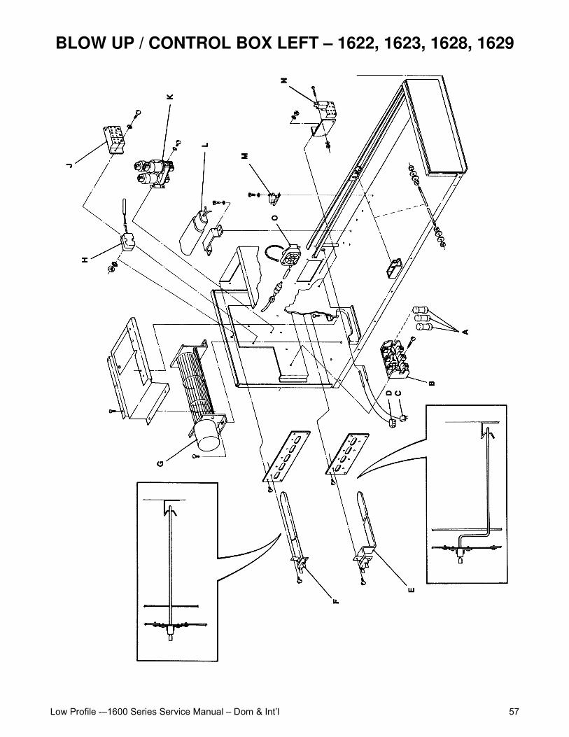
Low Profile -–1600 Series Service Manual – Dom & Int’l 57
BLOW UP / CONTROL BOX LEFT – 1622, 1623, 1628, 1629

Low Profile -–1600 Series Service Manual – Dom & Int’l58
PARTS / CONTROL BOX RIGHT – 1646, 1647, 1650, 1651LETTER PART # DESCRIPTION
A 369248 KnobB 369247 Shaft LockC 350224 Lens, YellowD 369704 Time/Temp. DisplayE 369467 Light, BurnerF 369520 Potentiometer(Temperature Control)G 369391 Potentiometer ( Conveyor Control)H 369507 Thermostat, Cooling FanJ 369579 Alarm, BurnerK 369173 Transformer, Time/Temp. DisplayL 369189 Terminal Block, 4-PoleM 369192 CapacitorN 369728 Temperature ControlO 369575 Air Pressure SwitchP 369786 ChainQ 369605 Transformer, Stepper ControlR 369573 Ignition ControlS 369066 SprocketT 369603 Motor, Gear Box Assy (Includes U & V)U 369737 Hall Effect SensorV 369736 MagnetW 369771 Switch, Burner ResetX 369368 Thermostat, Hi-LimitY 357107 FuseholderZ 369013 Fuse, 3A
369014 Fuse, 10AA A 369085 Junction BoxB B 369376 Terminal Block, 3-PoleC C 369589 Burner Blower MotorD D 369580 Gas Valve, Multi-BlockE E 369571 Connector, 4-PoleF F 369570 Connector, 3-PoleG G 369556 Orifice By-Pass, 1646
369557 Orifice By-Pass, 1647370053 Orifice, By-Pass, 1650, 1651
H H 369398 Solenoid ValveJ J 369757 Main Burner Orifice - 1646
369758 Main Burner Orifice - 1647370052 Main Burner Orifice - 1650370051 Main Burner Orifice - 1651
K K 369689 Pressure Tap FittingL L 369937 Burner Venturi & End Cap, 1646 Only
369773 Burner Venturi & End Cap, 1647 OnlyM M 369590 Igniter Sensor Assy.N N 369401 Air Shutter Assy.O O 369574 Spark GeneratorPP 369703 Blower Motor, Right HandQ Q 354258 Transformer, ControlR R 369640 Control, StepperS S 369747 Stand-OffT T 369735 ThermistorUU 369705 Thermocouple, Right HandV V 369508 Timer, 20 Minute
W W 369523 RelayX X 369738 Sail Switch Assy.Y Y 369260 Switch, On/OffZ Z 357036 Knob (Temperature Control)
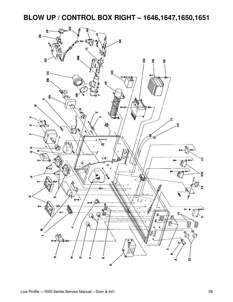
Low Profile -–1600 Series Service Manual – Dom & Int’l 59
BLOW UP / CONTROL BOX RIGHT – 1646,1647,1650,1651
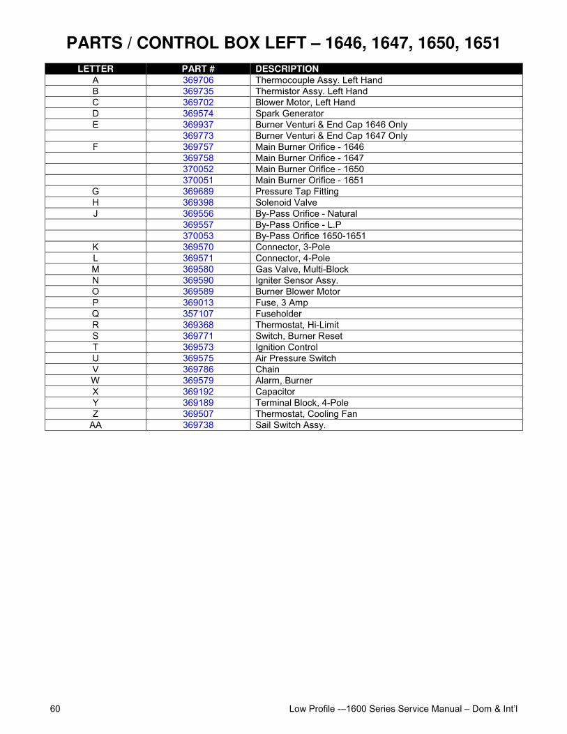
Low Profile -–1600 Series Service Manual – Dom & Int’l60
PARTS / CONTROL BOX LEFT – 1646, 1647, 1650, 1651LETTER PART # DESCRIPTION
A 369706 Thermocouple Assy. Left HandB 369735 Thermistor Assy. Left HandC 369702 Blower Motor, Left HandD 369574 Spark GeneratorE 369937 Burner Venturi & End Cap 1646 Only
369773 Burner Venturi & End Cap 1647 OnlyF 369757 Main Burner Orifice - 1646
369758 Main Burner Orifice - 1647370052 Main Burner Orifice - 1650370051 Main Burner Orifice - 1651
G 369689 Pressure Tap FittingH 369398 Solenoid ValveJ 369556 By-Pass Orifice - Natural
369557 By-Pass Orifice - L.P370053 By-Pass Orifice 1650-1651
K 369570 Connector, 3-PoleL 369571 Connector, 4-PoleM 369580 Gas Valve, Multi-BlockN 369590 Igniter Sensor Assy.O 369589 Burner Blower MotorP 369013 Fuse, 3 AmpQ 357107 FuseholderR 369368 Thermostat, Hi-LimitS 369771 Switch, Burner ResetT 369573 Ignition ControlU 369575 Air Pressure SwitchV 369786 ChainW 369579 Alarm, BurnerX 369192 CapacitorY 369189 Terminal Block, 4-PoleZ 369507 Thermostat, Cooling Fan
AA 369738 Sail Switch Assy.
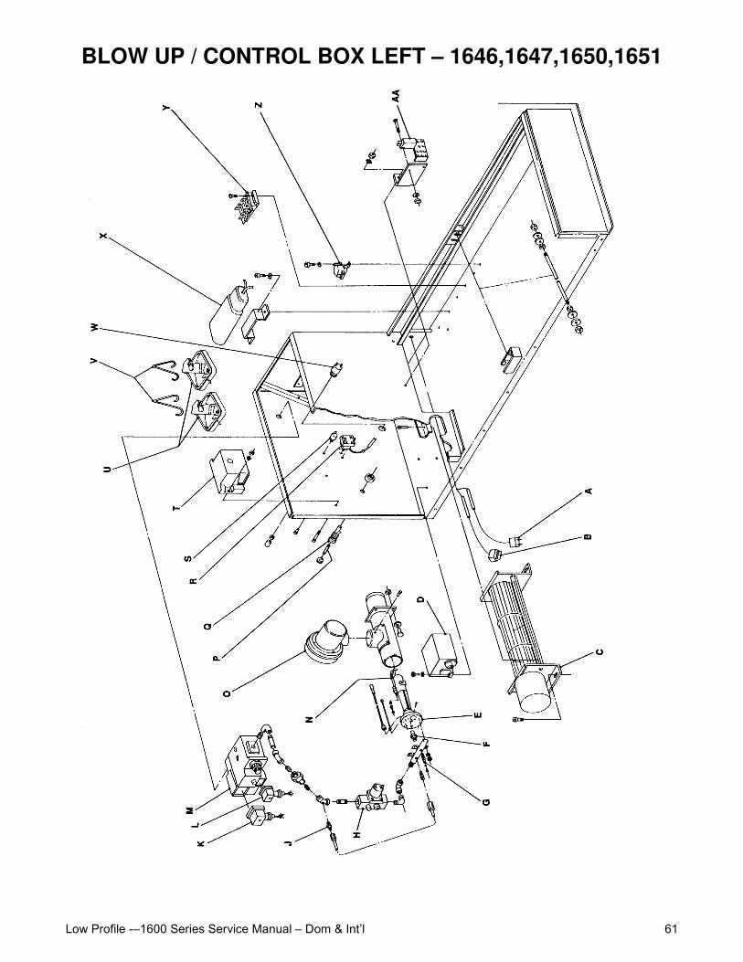
Low Profile -–1600 Series Service Manual – Dom & Int’l 61
BLOW UP / CONTROL BOX LEFT – 1646,1647,1650,1651
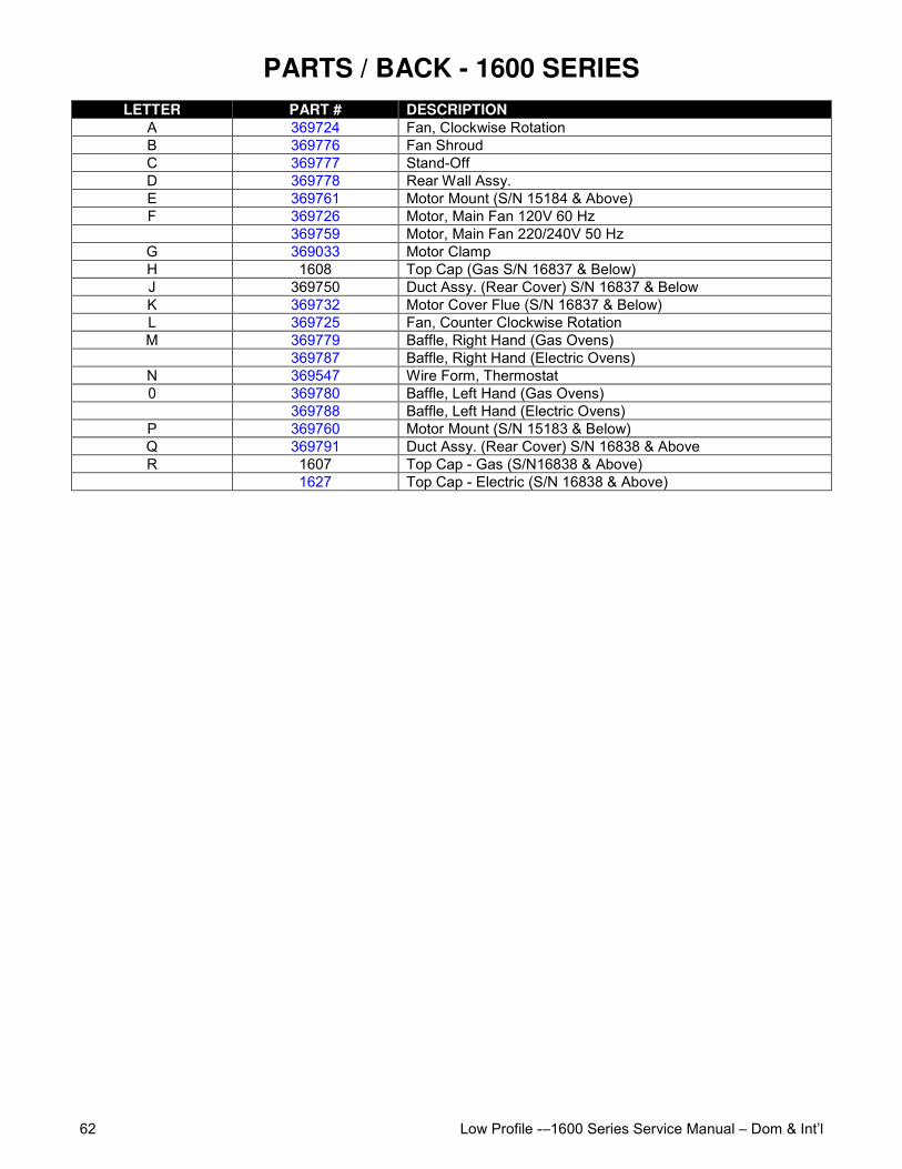
Low Profile -–1600 Series Service Manual – Dom & Int’l62
PARTS / BACK - 1600 SERIESLETTER PART # DESCRIPTION
A 369724 Fan, Clockwise RotationB 369776 Fan ShroudC 369777 Stand-OffD 369778 Rear Wall Assy.E 369761 Motor Mount (S/N 15184 & Above)F 369726 Motor, Main Fan 120V 60 Hz
369759 Motor, Main Fan 220/240V 50 HzG 369033 Motor ClampH 1608 Top Cap (Gas S/N 16837 & Below)J 369750 Duct Assy. (Rear Cover) S/N 16837 & BelowK 369732 Motor Cover Flue (S/N 16837 & Below)L 369725 Fan, Counter Clockwise RotationM 369779 Baffle, Right Hand (Gas Ovens)
369787 Baffle, Right Hand (Electric Ovens)N 369547 Wire Form, Thermostat0 369780 Baffle, Left Hand (Gas Ovens)
369788 Baffle, Left Hand (Electric Ovens)P 369760 Motor Mount (S/N 15183 & Below)Q 369791 Duct Assy. (Rear Cover) S/N 16838 & AboveR 1607 Top Cap - Gas (S/N16838 & Above)
1627 Top Cap - Electric (S/N 16838 & Above)
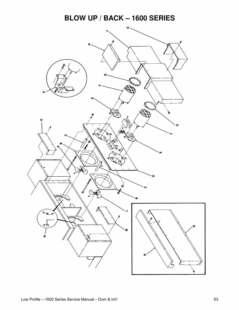
Low Profile -–1600 Series Service Manual – Dom & Int’l 63
BLOW UP / BACK – 1600 SERIES
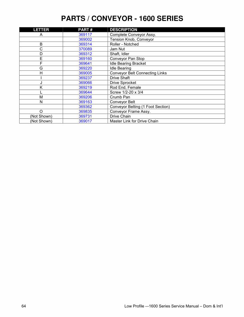
Low Profile -–1600 Series Service Manual – Dom & Int’l64
PARTS / CONVEYOR - 1600 SERIESLETTER PART # DESCRIPTION
A 369117 Complete Conveyor Assy.369002 Tension Knob, Conveyor
B 369314 Roller - NotchedC 370089 Jam NutD 369312 Shaft, IdlerE 369160 Conveyor Pan StopF 369641 Idle Bearing BracketG 369220 Idle BearingH 369005 Conveyor Belt Connecting LinksI 369237 Drive ShaftJ 369066 Drive SprocketK 369219 Rod End, FemaleL 369644 Screw 1/2-20 x 3/4M 369206 Crumb PanN 369163 Conveyor Belt
369362 Conveyor Belting (1 Foot Section)O 369835 Conveyor Frame Assy.
(Not Shown) 369731 Drive Chain(Not Shown) 369017 Master Link for Drive Chain
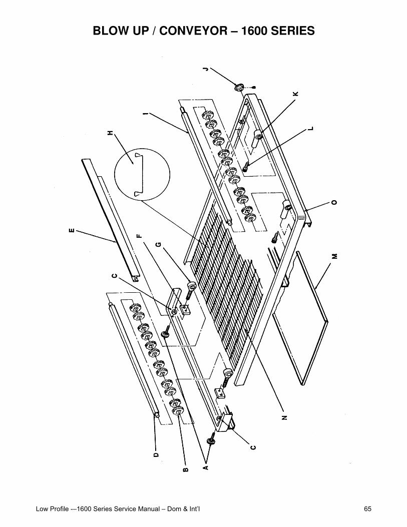
Low Profile -–1600 Series Service Manual – Dom & Int’l 65
BLOW UP / CONVEYOR – 1600 SERIES

Low Profile -–1600 Series Service Manual – Dom & Int’l66
This page intentionally left blank.

Low Profile -–1600 Series Service Manual – Dom & Int’l 67
This page intentionally left blank.

Low Profile -–1600 Series Service Manual – Dom & Int’l68