Embed Size (px)
Citation preview
Low-power Wireless ECG MonitoringSystem for Android Devices
Sistema inalambrico de bajo consumo para monitorizacionde electrocardiogramas desde dispositivos Android
Pablo Fernandez Vicente
Rafael Basilio de la Hoz Sevilla
Miguel Marquez Altuna
Proyecto de Sistemas Informaticos, Facultad de Informatica
Universidad Complutense de Madrid
Departamento de Arquitectura de Computadores y Automatica
Curso 2011/2012
Directores:
Luis Pinuel Moreno
Joaquın Recas Piorno

ii
Abstract
People affected by specific cardiovascular diseases require of a constant mon-
itoring of their vital signs, to which end specialized, high priced and big sized
equipment is employed. Reduction of the energetic requirements and improvement
of the portability are the objectives for the next generation of monitoring systems.
This document presents the development of a low-power wireless ECG monitor-
ing system for Android devices. By using the mobile phone or tablet of the user
the total amount of needed devices is limited, and the application of the 802.15.4
wireless communication standard substantially decreases the energetic consumption
when compared to wider spread ones like Bluetooth. The development of an USB
802.15.4 receiver device and the Android monitoring application results in a system
targeting an operation as unintrusive as possible. Systems like this one have proved
to be highly useful and a generalization of their employment is to be expected.
Keywords ECG, Android, MSP430, FreeRTOS, Shimmer, USB, 802.15.4
Las personas afectadas por ciertas enfermedades cardiovasculares requieren de
una estrecha vigilancia de sus constantes vitales, lo cual supone el empleo de equipos
especializados de elevado coste y tamano. La reduccion del consumo energetico y el
aumento de la portabilidad son los objetivos de la proxima generacion de dispositi-
vos de monitorizacion. En este documento se presenta el desarrollo de un sistema
inalambrico de monitorizacion electrocardiografica portatil de bajo consumo para
dispositivos Android. Al reutilizar el terminal del usuario se reduce el numero de
dispositivos necesarios, y la aplicacion del estandar de comunicacion inalambrica
802.15.4 disminuye el consumo de energıa de forma significativa respecto al uso de
otras alternativas como Bluetooth, la mas empleada en este ambito. El desarrollo
de un receptor USB 802.15.4 junto con la aplicacion de monitorizacion para An-
droid resulta en un sistema orientado a ser lo menos invasivo posible en la vida
del usuario final. Sistemas de estas caracterısticas han desmostrado ser de gran
utilidad y se espera un uso generalizado de los mismos en casos de necesidad de
monitorizacion constante.
Palabras clave ECG, Android, MSP430, FreeRTOS, Shimmer, USB, 802.15.4
iii

iv
Pablo Fernandez, Rafael de la Hoz and Miguel Marquez authorize Com-
plutense University of Madrid to spread and use this report and the asso-
ciated code, multimedia content and its results with academical and non-
comercial purposes, provided that its authors shall be explicitly mentioned.
June 28, 2012
Pablo Fernandez Rafael de la Hoz Miguel Marquez
v

vi
To Carlos, for his mad soldering skills and wise guidance,
to Fran because of his healthy support,
and very special thanks to everyone that has been there,
bearing with us.
vii

viii
Contents
Abstract iii
List of Figures xiii
Resumen en Espanol xv
1 Introduction 1
1.1 Project description . . . . . . . . . . . . . . . . . . . . . . . . 1
1.2 Project driver . . . . . . . . . . . . . . . . . . . . . . . . . . . 4
1.3 State of the art . . . . . . . . . . . . . . . . . . . . . . . . . . 6
1.4 Document overview . . . . . . . . . . . . . . . . . . . . . . . . 10
2 Hardware and Communications 13
2.1 Introduction . . . . . . . . . . . . . . . . . . . . . . . . . . . . 13
2.2 Overview . . . . . . . . . . . . . . . . . . . . . . . . . . . . . 14
2.3 Technology Research . . . . . . . . . . . . . . . . . . . . . . . 14
2.3.1 Google ADK & Arduino . . . . . . . . . . . . . . . . . 14
2.3.2 MSP430 . . . . . . . . . . . . . . . . . . . . . . . . . . 15
2.3.3 ShimmerTM . . . . . . . . . . . . . . . . . . . . . . . . 17
2.3.4 802.15.4 . . . . . . . . . . . . . . . . . . . . . . . . . . 18
2.3.5 FreeRTOS . . . . . . . . . . . . . . . . . . . . . . . . . 22
2.3.6 USB device & USB host . . . . . . . . . . . . . . . . . 22
2.4 Description . . . . . . . . . . . . . . . . . . . . . . . . . . . . 23
2.5 Milestones . . . . . . . . . . . . . . . . . . . . . . . . . . . . . 25
2.5.1 Arduino for Android USB Device Comunication . . . 26
2.5.2 MSP430 for Android USB Host Comunication . . . . 27
2.5.3 USB in FreeRTOS . . . . . . . . . . . . . . . . . . . . 30
2.5.4 802.15.4 in FreeRTOS . . . . . . . . . . . . . . . . . . 32
2.5.5 802.15.4 & USB coexistence under FreeRTOS . . . . . 34
2.5.6 MSP430 based device design . . . . . . . . . . . . . . 36
ix
2.5.7 Final Validation and Release Candidate Version . . . 39
2.6 Closure . . . . . . . . . . . . . . . . . . . . . . . . . . . . . . 39
3 Software Development 41
3.1 Introduction . . . . . . . . . . . . . . . . . . . . . . . . . . . . 41
3.2 Overview . . . . . . . . . . . . . . . . . . . . . . . . . . . . . 42
3.3 Requirements . . . . . . . . . . . . . . . . . . . . . . . . . . . 43
3.3.1 Functional Requirements . . . . . . . . . . . . . . . . 43
3.3.2 Non-functional Requirements . . . . . . . . . . . . . . 43
3.4 Risk Analysis . . . . . . . . . . . . . . . . . . . . . . . . . . . 44
3.5 Use Cases . . . . . . . . . . . . . . . . . . . . . . . . . . . . . 49
3.5.1 UC1. View data from Bluetooth . . . . . . . . . . . . 50
3.5.2 UC2. View data from USB Receiver . . . . . . . . . . 51
3.5.3 UC3. View data from log file . . . . . . . . . . . . . . 52
3.5.4 UC4. Adjust view parameters . . . . . . . . . . . . . . 52
3.6 Design and Architecture . . . . . . . . . . . . . . . . . . . . . 53
3.6.1 View Package . . . . . . . . . . . . . . . . . . . . . . . 56
3.6.2 Data Management Package . . . . . . . . . . . . . . . 57
3.6.3 Utilities Package . . . . . . . . . . . . . . . . . . . . . 60
3.6.4 Data Flow Model Realizations . . . . . . . . . . . . . 61
3.7 Development Process . . . . . . . . . . . . . . . . . . . . . . . 65
3.7.1 Project Scheduling . . . . . . . . . . . . . . . . . . . . 65
3.7.2 Iteration 1 . . . . . . . . . . . . . . . . . . . . . . . . . 67
3.7.3 Iteration 2 . . . . . . . . . . . . . . . . . . . . . . . . . 69
3.7.4 Iteration 3 . . . . . . . . . . . . . . . . . . . . . . . . . 70
3.7.5 Iteration 4 . . . . . . . . . . . . . . . . . . . . . . . . . 72
3.7.6 Final Validation . . . . . . . . . . . . . . . . . . . . . 73
3.8 Closure . . . . . . . . . . . . . . . . . . . . . . . . . . . . . . 74
4 Results 77
4.1 Final state . . . . . . . . . . . . . . . . . . . . . . . . . . . . . 77
4.2 Potential additions and expansions . . . . . . . . . . . . . . . 78
4.3 Findings . . . . . . . . . . . . . . . . . . . . . . . . . . . . . . 82
A Budget Analysis 87
A.1 Project tasks and scheduling . . . . . . . . . . . . . . . . . . 88
A.1.1 Hardware project tasks . . . . . . . . . . . . . . . . . 88
A.1.2 Software project tasks . . . . . . . . . . . . . . . . . . 90
A.2 Asset cost . . . . . . . . . . . . . . . . . . . . . . . . . . . . . 94
x
B Product Cost 95
C Receiver Specification Documents 99
C.1 Bill Of Materials . . . . . . . . . . . . . . . . . . . . . . . . . 99
C.2 Schematic . . . . . . . . . . . . . . . . . . . . . . . . . . . . . 100
C.3 Printed Circuit Board Design . . . . . . . . . . . . . . . . . . 101
Bibliography 103
xi

xii
List of Figures
2.1 Superframe structure with GTSs . . . . . . . . . . . . . . . . 19
2.2 Communication to a coordinator in a beacon-enabled PAN . 20
2.3 Shimmer power consumption analysis, beacon reception . . . 21
2.4 Shimmer power consumption analysis, beacon reception and
data transmission . . . . . . . . . . . . . . . . . . . . . . . . . 21
3.1 Architecture overview . . . . . . . . . . . . . . . . . . . . . . 54
3.2 Data-flow model realization . . . . . . . . . . . . . . . . . . . 56
3.3 DataManager interface . . . . . . . . . . . . . . . . . . . . . . 58
3.4 DataSourceThread class . . . . . . . . . . . . . . . . . . . . . 58
3.5 DataHolder interface . . . . . . . . . . . . . . . . . . . . . . . 59
3.6 Bluetooth Model Realization . . . . . . . . . . . . . . . . . . 62
3.7 File Reader Model Realization . . . . . . . . . . . . . . . . . 63
3.8 USB Model Realization . . . . . . . . . . . . . . . . . . . . . 64
xiii

xiv
Resumen en Espanol
En este documento se expone la investigacion realizada con el objetivo de
desarrollar un receptor del estandar de redes de area personal inalambricas
802.15.4 del IEEE para dispositivos Android a traves de USB, aplicado a un
sistema completo de monitorizacion electrocardiografica (ECG), ası como el
proceso de desarollo del mismo. Este sistema se enmarca en el ambito de la
atencion sanitaria personal: su principal aplicacion es la montorizacion del
estado del corazon por parte de un particular, eliminando la dependencia,
respecto a esta tarea especıfica, con los sistemas de atencion sanitaria tra-
dicionales.
Recientemente ha surgido un gran interes, tanto en el ambito academico
como en el industrial, en la produccion de sistemas de monitorizacion ECG
portatiles y de bajo consumo, llegando a ser una de las principales aplica-
ciones de las redes de sensores corporales inalambricas.
Para maximizar la portabilidad, en el desarrollo de estos sistemas se han
empezado a emplear dispositivos moviles de gran capacidad de computo,
particularmente smartphones, debido a la gran difusion que han tenido en
los ultimos anos. En el 2011 se presento un sistema, colaboracion entre
la Universidad Complutense de Madrid (UCM) y la Ecole Polytechnique
Federale de Lausanne (EPFL), para monitorizacion ECG de ambito perso-
nal empleando un iPhone como visualizador y Bluetooth como tecnologıa
de comunicacion inalambrica.
De los resultados obtenidos por ese proyecto surge la presente iniciativa que
trata de llevar al siguiente nivel las caracterısticas inherentemente buenas de
bajo consumo y bajo coste del mismo mediante la aplicacion del protocolo
802.15.4, de mucho menor consumo energetico que la tecnologıa Bluetooth,
y la sustitucion del dispositivo iOS por uno basado en Android, debido a su
mayor accesibilidad y el menor coste, en general, de estos.
xv
El sistema desarrollado en este proyecto presenta al usuario una represen-
tacion visual de su onda ECG en tiempo real, resaltando puntos relevantes
para simplificar la compresion de los datos mostrados. Tambien muestra in-
formacion sobre el ritmo cardiaco, y toda esta informacion es almacenada
de forma transparente al usuario para su posterior consulta.
Esta funcionalidad es posible gracias a la operacion conjunta de los tres dis-
positivos que forman el sistema de monitorizacion: el nodo de delineacion
ECG, el receptor 802.15.4 y el dipositivo Android que actua de interfaz con
el sistema. El nodo de delineacion ECG va conectado a la red de sensores
corporal del usuario y se encarga de la captura y posterior analisis de la onda
ECG, ası como de la codificacion y envıo de la misma de forma inalambrica.
El receptor 802.15.4 conectado al sistema Android a traves de USB controla
la recepcion de datos a traves de dicho protocolo y el envıo de la informacion
recibida al dispositivo Android. Este actua como decodificador y visualiza-
dor en tiempo real, y, como interfaz con el sistema, gestiona las conexiones
inalambricas y almacena y muestra los datos recibidos.
Los objetivos del proyecto son, entonces, el desarrollo de la aplicacion para
dispositivos Android, la produccion del receptor 802.15.4 y la comunicacion
de ambos con un nodo delineador ECG ya existente.
La aplicacion para dispositivos Android, como ya se ha mencionado, es la
interfaz con la que el usuario interactua con el sistema. Su diseno sigue las
practicas comunes de aplicaciones para este sistema operativo ya que el ob-
jetivo es que la curva de aprendizaje sea, si no nula, muy suave. Los motivos
para emplear Android como sistema operativo base son tres: la importancia
de este entre los sistemas operativos moviles, el mayor rango de precios de
los terminales que lo soportan, que permite una mayor difusion del sistema
debido a la existencia de dispositivos de precio mas reducido, y la naturaleza
libre y de codigo abierto del entorno de desarrollo, caracterıstica que facilita
la posterior expansion del sistema. Todos estos motivos pueden resumirse
en que el empleo de Android como sistema operativo permite el acceso de
un mayor numero de usuarios al mismo.
En cuanto al nodo delineador de la onda ECG, el objetivo es emplear uno
ya desarrollado para el proyecto. Esto es ası porque tanto el nodo delineador
como la red de sensores corporales que capturan la onda ECG son sistemas
xvi
especialmente complejos cuyos desarrollos ocuparıan, cada uno, un proyecto
de la envergadura del actual. Es mas, el nodo empleado es el resultado de
la colaboracion de dos universidades europeas y una nod tesis doctoral.
El nodo delineador que se emplea en el proyecto es obtenido en el proyecto
de la UCM y la EPFL antes mencionado. Este nodo se desarrollo inicial-
mente como un delineador de electrocardiografıa en tiempo real de bajo
consumo con capacidad para envıar los datos de forma inalambrica a traves
de Bluetooth. En otro esfuerzo conjunto entre la EPFL y la UCM se doto al
nodo de funcionalidad para el envıo empleando 802.15.4, pero tan solo al
nivel necesario para realizar algunas estimaciones de consumo. Incluso con
la utilizacion real del estandar 802.15.4 estando aun por llegar, el nodo pre-
senta las caracterısticas necesarias para convertirse en un excelente punto
de partida para el alcance de los objetivos del proyecto.
El componente mas importante del sistema en cuanto a este proyecto se re-
fiere es el receptor USB de 802.15.4 en tiempo real para dispositivos Android.
Su desarrollo es una necesidad puesto que los dispositivos Android actual-
mente no proporcionan soporte para el protocolo 802.15.4, aunque sı para
otros como Bluetooth o Wi-Fi. Considerando que en el nodo delineador que
se toma como punto de partida para el sistema la operacion que supone
mayor consumo de baterıa es la utilizacion de la infraestructura Bluetooth,
como confirman los estudios realizados por la UCM y la EPFL, la produc-
cion del receptor 802.15.4 es, pues, imperativa.
La existencia de otros proyectos con el objetivo de la dotacion a dispositi-
vos moviles del estandar 802.15.4 es un hecho conocido desde el inicio del
proyecto, aunque estos no tengan como objetivo el campo de la biomedicina
o la monitorizacion personal. El motivo para no apoyar o emplear alguno
de ellos es doble: por un lado, al comienzo del proyecto estas iniciativas
se encuentran o bien inconclusas o bien paralizadas; mas aun, todas son
proyectos aislados, generalmente desarrollados por una unica persona y sin
ningun tipo de soporte oficial ni garantıas de finalizacion. Por otra parte, y
siguiendo la idea de obtencion de un sistema de tamano reducido, el objetivo
de este proyecto es emplear el dispositivo Android como maestro en la co-
municacion USB, de forma que el receptor 802.15.4 obtenga la alimentacion
a traves de el, eliminando ası la necesidad de emplear una baterıa que incre-
mentarıa el tamano del receptor. Ninguno de los proyectos existentes emplea
la capacidad de los dispositivos Android para asumir el rol de maestro en la
xvii
comunicacion, ası que no son de utilidad real para el proyecto.
El desarrollo del proyecto viene motivado por dos razones principales: la
potencial utilidad que demuestra tener un sistema de estas caracterısticas y
el interes que suscita a nivel academico.
Segun la Organizacion Mundial de la Salud (OMS), las enfermedades cardio-
vasculares representan la principal causa de mortalidad a nivel mundial. Sin
embargo, la vigilancia que requieren las personas afectadas no es asumible,
por lo general, por los sistemas de sanidad tradicionales. La monitorizacion
domestica continua supondrıa una gran ayuda para estas personas, pero to-
davıa se trata un objetivo a cumplir.
En un escenario como este, las redes inalambricas de sensores corporales
(wireless body sensor networks, WBSN) se presentan como herramientas
de monitorizacion eficientes y asumibles economicamente. Particularmente,
las WBSN aplicadas a la monitorizacion electrocardiografica son de gran
utilidad en el seguimiento de enfermedades cardiovasculares. De hecho, pro-
yectos como el de la UCM y la EPFL mecionado anteriormente promueven
la expansion de sistemas como estos.
Ademas, con el uso de dispositivos portatiles, en particular smartphones,
para mostrar los resultados de la monitorizacion se persigue la expansion de
estos sistemas en todos los ambitos de la sociedad, ya que permiten integrar
el sistema en dispositivos ampliamente utilizados, evitando ası la necesidad
de cargar con aparatos adicionales. La eleccion de Android como plataforma
reponde a los factores de difusion y menor coste de los terminales que se
mencionaron anteriormente, con el objetivo principal de maximizar la ex-
pansion del sistema.
Asimismo se busca el uso mas extendido del sistema con el aumento de la
duracion de la baterıa y la reduccion del tamano de los nodos de monitori-
zacion: un consumo de baterıa menos exigente permite un numero menor de
interrupciones en la monitorizacion producidas durante el proceso de carga
de la misma, mientras que el menor tamano del dispositivo facilita el em-
leo contınuo del mismo. La utilizacion del estandar 802.15.4 responde a la
busqueda de la realizacion de estos objetivos.
En conjunto, el uso de un dispositivo Android con capacidad de recepcion
xviii
802.15.4 en un sistema de monitorizacion electrocardiografica continua re-
baja los requisitos de consumo de baterıa y tamano del sistema completo, y
de esta forma mejora la posibilidad de ser transportado y relaja las restric-
ciones en su aplicacion.
Desde un punto de vista academico, la principal motivacion que plantea el
desarrollo de este proyecto es el hecho de que reune practicamente todas las
areas de la carrera de Ingenierıa Informatica. Desde el mismo comienzo el
proyecto implica desarrollo tanto software como hardware ademas de inves-
tigacion en ambitos externos al alcance de la propia carrera, como tecno-
logıas inalambricas de bajo consumo o desarrollo para dispositivos moviles,
ası como tareas de diseno y desarrollo en un amplio rango de niveles de
abstraccion.
Se espera tambien que las tecnologıas basadas en la especificacion del estandar
802.15.4 del IEEE como ZigBee veran incrementada su relevancia a medio
plazo debido a sus potenciales aplicaciones en campos como la domotica y
la biomedicina, entre otros.
Ademas, tanto el desarrollo de aplicaciones como de accesorios para smartp-
hones u otro tipo de dispositivos portatiles son unas de las practicas mas
habituales hoy en dıa en el ambito del desarrollo de sistemas informaticos, y
representan algunas de las actividades mas demandadas. Por tanto, entrar
en contacto con ellas proporciona una experiencia adicional en un campo
puntero que no hace sino amplıar nuestro rango de habilidades y, por consi-
guiente, incrementa nuestro valor en el mercado laboral.
Al comienzo del proyecto, evaluando los objetivos, se decide hacer una dis-
tincion muy clara entre dos partes del proyecto: por un lado, el desarrollo de
la aplicacion para Android y por otro, la investigacion orientada al posterior
desarrollo del receptor 802.15.4 ası como la correcta utilizacion del nodo de-
lineador seleccionado incluyendo las modificaciones que hubiera que hacerle
al mismo.
El desarrollo la aplicacion Android se trata de un proyecto de desarrollo
software de tamano manejable cuyo mayor riesgo consiste en la falta de
formacion del equipo en el ambito del desarrollo de aplicaciones para dispo-
sitivos moviles.
xix
Por su parte, el desarrollo del receptor 802.15.4 implica un esfuerzo de inves-
tigacion hardware importante, ya que la mayorıa de los objetivos planteados
ni siquiera se sabe si son alcanzables. Es mas, el desarrollo de dispositivos
electronicos al nivel requerido por el proyecto queda fuera del alcance de la
formacion recibida. Todo esto provee a la parte de desarrollo e investigacion
sobre hardware de un nivel de incertidumbre, tanto en la posibilidad real
de alcanzar los objetivos propuestos, como en la capacidad del equipo para
llevarlos a cabo, muy superior al existente en el desarrollo software.
Esta situacion propicia la division del proyecto en dos subproyectos a desa-
rrollar de forma independiente pero teniendo en cuenta en todo momento la
estrecha relacion entre uno y otro. De esta forma en cada desarrollo se pue-
den aplicar las metodologıas, tecnicas y planificaciones mas apropiadas para
el tipo de trabajo concreto a realizar. Atendiendo a la estrecha dependencia
entre los dos proyectos, y buscando evitar grandes descompensaciones entre
ambos, se fija una planificacion comun a todo el proyecto de forma que cier-
tos hitos deben alcanzarse a la par en ambos desarrollos.
De esta forma se asegura que la funcionalidad producida por un proyecto
se completa en el otro mientras se deja libertad para aplicar el enfoque que
se considere mas efectivo en cada proyecto durante los ciclos de desarrollo.
Ademas, dada la incertidumbre asociada a la investigacion hardware, los pla-
zos temporales para los hitos se asumen como variables y se manejan planes
de actuacion en la planificacion del proyecto de desarrollo software para que
el trabajo no se vea detenido por los potenciales retrasos. Se considera, en-
tonces, que el camino crıtico del proyecto esta definido por el proyecto de
investigacion y desarrollo hardware y el proyecto de desarrollo software debe
adaptarse a sus necesidades. Aun y ası en la planificacion del primero no
se dejan de tener en cuenta las posibles contingencias del desarrollo software.
La tecnologıa seleccionada para el desarrollo del proyecto es la siguiente:
• El dispositivo movil tipo tableta basado en Android Motorola Xoom
Escogido entre otros modelos de terminales que soportan Android por
su capacidad para asumir el rol de maestro en la comunicacion USB.
Ademas, la capacidad del procesador que incorpora y el hecho de in-
tegrar una GPU lo hacen especialmente aplicable para la consecucion
del objetivo de mostrar los datos de la electrocardiografıa en tiempo
real.
xx
• Nodo delineador de ECG del proyecto de la UCM y la EPFL
Este nodo se basa en la plataforma inalambrica de sensores corpora-
les Shimmer para la captura de la onda electrocardiografica y realiza
un analisis de la misma (denominado delineacion), enviando los datos
a traves de Bluetooth o, potencialmente, 802.15.4. El firmware que
ejecuta el nodo se encuentra completamente desarrollado y validado
al comienzo del presente proyecto, salvo la funcionalidad de envıo a
traves de 802.15.4, que si bien esta implementada en el dispositivo, no
se ha probado de forma exhaustiva.
• La familia de microprocesadores de 16 bits MSP430 de la firma Texas
Instruments
Su eleccion se realiza teniendo en cuenta tanto su reducido consumo
de energıa como la sencillez en su programacion, que permite utilizar
C y depurar a traves del estandar JTAG; pero principalmente por el
hecho de que el nodo delineador ECG a emplear en el sistema uti-
liza esta misma familia de microprocesadores, y existe la posibilidad
de reutilizar parte del codigo, especialmente el sistema operativo y la
funcionalidad relacionada con envıo inalambrico a traves de 802.15.4.
• Sistema operativo de tiempo real FreeRTOS para dispositivos empotra-
dos
El empleo de este sistema operativo viene determinado por la eleccion
del nodo delineador, ya que este emplea FreeRTOS y la implemen-
tacion de la capa MAC 802.15.4 para dicho sistema operativo se en-
cuentra disponible y puede ser aplicada en el proyecto. Es mas, dado
que el microprocesador que llevara el receptor a desarrollar es muy
similar al del nodo delineador, el sistema operativo puede ser utili-
zado directamente en el receptor sin esperar la necesidad de muchas
modificaciones. Como se menciona antes, la implementacion de la ca-
pa MAC 802.15.4 para FreeRTOS implementacion no esta totalmente
completa, pero es un buen punto de partida.
Cada tecnologıa se aplica en uno de los subsistemas que forman el sistema
completo. Aunque se ha trabajado tambien con otras tecnologıas, estas se
iran mencionando a lo largo de la exposicion del desarrollo del proyecto que
se realiza a continuacion, y por tanto se omite su enumeracion en este pun-
to. Se analiza primero el desarrollo relacionado con la parte de hardware del
xxi
proyecto.
El subproyecto de hardware contempla dos fases: por un lado la investigacion
sobre la factibilidad y la forma de alcanzar los objetivos propuestos, y por
otro el desarrollo necesario para alcanzar dichos objetivos. Los objetivos
concretos de este subproyecto son:
1. Lograr la comunicacion de un microprocesador MSP430 mediante USB
con el dispositivo Android
2. Inclusion de capacidad de comunicacion a traves USB en FreeRTOS
3. Empleo de 802.15.4 en FreeRTOS en el procesador MSP430 seleccio-
nado
4. Asegurar la correcta operacion de los modulos USB y 802.15.4 sobre
FreeRTOS
5. Disenar el circuito impreso especıfico para dispositivo receptor USB
802.15.4
6. Validacion y produccion del dispositivo receptor a partir del diseno
Debido a las restricciones de tiempo y de disponibilidad del equipo al tener
que hacer frente a este subproyecto en paralelo con el desarrollo software, se
toma la decision de establecer estos objetivos como los hitos para la planifi-
cacion, anadiendo uno extra que contempla una fase de prototipado inicial
sobre una placa Arduino, que es bastante mas sencillo que trabajar direc-
tamente con un MSP430 y sirve como toma de contacto inicial. Como se
menciona anteriormente, los plazos para estos hitos se establecen tentativa-
mente debido a la incertidumbre de cada objetivo.
Cabe mencionar que en lugar de separar las fases de investigacion y desarro-
llo asociadas a cada objetivo se opta por no establecer lımites fijos entre ellas,
de forma que cada objetivo comienza con el planteamiento de las potenciales
lıneas de investigacion del mismo. Seguidamente comienza el desarrollo de
una de las lıneas de investigacion propuestas, y si se llega a un resultado
negativo, se descarta el trabajo y se selecciona otra lınea de investigacion.
Este sistema, cercano a las metodologıas de desarrollo extremas basadas en
prototipos, junto con la flexibilidad de la planificacion propuesta ha resul-
tado ser clave para la correcta consecucion de los objetivos del subproyecto
xxii
de hardware.
Detallamos ahora el proceso de desarrollo del subproyecto de software. Sien-
do este mas cercano a un desarrollo tradicional, con menos incertidumbre en
cuanto al resultado, se opta por aplicar una metodologıa de desarrollo orde-
nada con la que se asegure el cumplimiento de los plazos establecidos por el
subproyecto de hardware. Debido a que se aplican las mismas restricciones
temporales y de comparticion de recursos que las expuestas anteriormente
para el subproyecto de hardware, precisamente por la conduccion de ambos
en paralelo, se descarta la aplicacion de metodologıas de desarrollo con gran
dependencia de la produccion de artefactos, ası como de metodologıas que
requieran planificaciones fijas.
Se opta, entonces, por la aplicacion de una metodologıa hıbrida entre una
metodologıa iterativa y una metodologıa de desarrollo rapido. Esto se tradu-
ce en el establecimiento de una planificacion inicial en base a los objetivos del
subproyecto de hardware. Esta planificacion empareja los hitos del desarrollo
hardware con la funcionalidad correspondiente de la aplicacion Android y,
centrandose en construir la mayor cantidad de funcionalidad posible cuanto
antes, distribuye el resto de objetivos del subproyecto software. Ademas es
necesario asumir en todo momento la posibilidad de una modificacion en las
fechas.
Para hacer frente a ese tipo de contingencias se decide aplicar tecnicas pro-
pias de metodologıas iterativas como el analisis de riesgos y el desarrollo
basado en casos de uso. De esta forma se mantiene el foco en el desarrollo
de la funcionalidad clave aun cuando sea necesario un reajuste de los plazos
o una mayor dedicacion de recursos al subproyecto de hardware.
Los casos de uso identificados para el sistema son los siguientes:
• UC1. Visualizar datos obtenidos por Bluetooth
• UC2. Visualizar datos obtenidos por receptor USB
• UC3. Visualizar datos de un archivo de log
• UC4. Ajustar parametros de visualizacion
Como el receptor USB 802.15.4 es la culminacion de la investigacion hard-
ware, la planificacion de los esfuerzos de desarrollo se plantea de forma que
xxiii
todo el resto de la funcionalidad se construya y valide mientras el subproyec-
to de hardware desarrolla un prototipo del receptor, y una vez se tenga este
prototipo se proceda a la implementacion de la funcionalidad relacionada
mientras se desarrolla la version final. Gracias a este tipo de planificacion y
al minucioso analisis de riesgos llevado a cabo durante todo el desarrollo, los
objetivos del subproyecto de software tambien han sido alcanzados de forma
satisfactoria.
Se ha logrado, entonces, la produccion de un sistema de monitorizacion
electrocardiografica en tiempo real de bajo consumo y tamano reducido em-
pleando un dispositivo Android como interfaz con el usuario y el estandar
802.15.4 como protocolo de transmision de datos inalambrico. Este sistema
provee toda la funcionalidad requerida: visualizacion de la onda ECG en
tiempo real proveniente de nodos tanto 802.15.4 como Bluetooth, almacena-
miento de esta de forma permanente en archivos y su posterior visualizacion,
ası como capacidad para configurar los parametros de la visualizacion tanto
en tiempo real como de archivos. El sistema es, pues, una version mas acce-
sible gracias al empleo de dispositivos Android y con un consumo energeti-
co dos ordenes de magnitud menor del sistema producido en 2011 por la
Universidad Complutense de Madrid y la Ecole Polytechnique Federale de
Lausanne, lo cual es el principal objetivo del proyecto.
Este hito se alcanza gracias a la correcta finalizacion tanto del subproyecto
de investigacion hardware como del de desarrollo software en que se dividide
el proyecto. Las diferencias en el enfoque requeridas por cada subproyecto
sumadas a la estricta dependencia entre ambos resultaban una complicacion
anadida en la prevision del resultado de los dos desarrollos; pero, gracias a
la aplicacion de planificaciones flexibles pero de objetivos firmes en cada uno
que no dejaban de tener en cuenta posibles complicaciones en el otro, y que
contaban con planes tanto de contingencia como de actuacion ante ellas, se
manejaron correctamente ambos proyectos, dando lugar al actual estado de
finalizacion satisfactoria del proyecto.
En cuanto al subproyecto de hardware, la produccion del receptor USB de
802.15.4 para dispositivos Android se ha llevado a cabo con exito. El disposi-
tivo ha evolucionado desde las primeras etapas donde se empleaba una placa
de prototipado hasta llegar a ser un circuito integrado disenado expresamen-
te para el proyecto. Este circuito integrado esta completamente disenado y
validado, que en el momento en el que se escribe este documento esta en
xxiv
proceso de fabricacion. En su lugar se ha utilizado un prototipo, de tamano
algo mas reducido pero construido a partir del diseno final de la placa, para
la validacion del sistema.
Las dimensiones del prototipo son 7.25 x 6.35 x 3.5 cm y necesita 3.3V de
alimentacion, aunque es utilizable a partir de 3.0V. La conexion USB es la
que proporciona esta alimentacion y ademas permite emplear el dispositivo
en cualquier sistema capaz de comunicarse mediante HID, y ha sido proba-
do con exito tanto en dispositivos Android como en ordenadores ejecutando
varias versiones de Windows.
Con respecto a la aplicacion para terminales Android producida en el sub-
proyecto de software, proporciona toda la funcionalidad que entra dentro de
los objetivos del proyecto de forma robusta y con un diseno similar al de
las aplicaciones canonicas de Android. Es una aplicacion, dentro del domi-
nio especıfico de la monitorizacion electrocardigrafica, con funcionalidad de
proposito general, que requerirıa cierta especializacion para ser realmente
util. Esta especializacion debera anadir funcionalidad para el escenario de
aplicacion particular, y el analisis de esos escenarios o la posible implemen-
tacion de alguno de ellos queda fuera de los objetivos del proyecto.
En cualquier caso, siendo conscientes de la necesidad de especializacion fu-
tura de la aplicacion, durante el diseno y desarrollo de la misma se puso
un gran enfasis en que, ademas de ofrecer la funcionalidad requerida, pro-
porcionase un conjunto de herramientas tal que pudiera actuar como un
framework sobre el cual se pueda realizar el desarrollo de aplicaciones de
monitorizacion ECG mas especıficas. Como detalle, mencionar que ademas
de que el sistema esta preparado para la inclusion sencilla de nuevas fuen-
tes de datos ademas de Bluetooth, 802.15.4 y archivos, la fuente de datos
de 802.15.4 en realidad es un dispositivo USB, en concreto el receptor, por
lo que podrıa emplearse cualquier otro periferico que enviase datos con la
codificacion esperada en su lugar.
Esto da una idea de la flexibilidad buscada, y alcanzada, del sistema de mo-
nitorizacion desarrollado. Apoyandose en ella, se plantean potenciales lıneas
de trabajo futuro, distinguiendo entre las que se podrıan realizar a corto
plazo y las que serıan ya para un medio o largo plazo.
Por un lado, un particular afectado de una enfermedad cardiovascular que
xxv
requiere de monitorizacion electrocardiografica constante, observando los ob-
jetivos y los resultados del proyecto actual, presento al departamento un
proyecto de especializacion del sistema desarrollado para sus necesidades
particulares, que son comunes al colectivo de afectados por dicha enfer-
medad. Este nuevo sistema ha de incorporar, ademas de la funcionalidad
presente en el actual, algunas caracterısticas nuevas:
• Etiquetado de eventos durante la delineacion, de forma que el usua-
rio pueda indicar al sistema en que momentos se encuentra mal y la
informacion quede almacenada junto a la onda ECG. De esta forma
podrıa estudiarse posteriormente la informacion guardada de forma
mas detallada para mejorar la compresion del estado del paciente.
• Adicion de informacion temporal a los logs, de manera que el usuario
pueda consultar directamente la onda ECG relativa a un momento
concreto en el que se encontro mal, o que pueda saltar al momento
indicado por un marcador de eventos. Esto facilitarıa la consulta y
navegacion por los datos almacenados.
• Comandos de voz que permitan interactuar con el sistema sin nece-
sidad de emplear las manos, ya que, ya sea por su estado de salud o
porque las tenga ocupadas, es posible que el usuario no pueda manejar
la aplicacion.
• Avisos automaticos en caso de que se produzca algun evento relevante
relacionado con la salud del usuario, de manera que se pueda alertar al
mismo, algun pariente o personal cualificado en caso de ser necesario.
Ademas, estos avisos podrıan hacerse de varias formas, ya sea a traves
de mensaje, correos electronicos con localizacion GPS adjunta o incluso
llamadas de voz automaticas directamente.
Por otra parte, se contemplan una serie de expansiones del sistema mas a
largo plazo, debido sobre todo a que requieren de mas tiempo y recursos,
aparte de una planificacion especıfica. En primer lugar se proponen mejo-
ras enfocadas a la monitorizacion de varios pacientes, para un entorno mas
profesional, en dos posibles versiones:
• Dado que el receptor desarrollado tambien es compatible con disposi-
tivos que soporten el protocolo HID, se propone utilizarlo conectado
a un PC que actue como servidor, recibiendo los datos ECG proce-
dentes de los nodos de varios pacientes. Una vez estos datos estan en
xxvi
el servidor, la propia aplicacion Android permitirıa conectarse a este
para descargarlos y visualizarlos en el dispositivo.
• Teniendo en cuenta que la pantalla de un tablet es relativamente gran-
de, se puede aprovechar para mostrar los resultados de la monitoriza-
cion de varios pacientes a la vez. Como parte de esta nueva funcio-
nalidad tambien se encontrarıa la de cambiar entre la onda ECG de
otros pacientes, guardado de logs simultaneo y subida a un servidor
dedicado.
Tambien a largo plazo, aunque en el campo de la automonitorizacion, se
plantea la adaptacion del sistema a dominios particulares que imponen re-
quisitos adicionales debido, sobre todo, al entorno en el que se utilizarıa.
En este sentido, el director del Laboratorio de Sistemas Empotrados (ESL)
de la EPFL (equipo responsable junto a la UCM del desarrollo del nodo
delineador que se usa en este proyecto) ha mostrado interes en la aplicacion
de los bajos requisitos de consumo del sistema en otro proyecto de la EPFL
con el que esta colaborando, el Solar Impulse.
Este proyecto en concreto trata de conseguir un vuelo alrededor del mun-
do evitando el uso de carburantes de cualquier tipo, utilizando unicamente
energıa solar. El avion utilizado es de una unica plaza, por lo que las cons-
tantes vitales del piloto deben estar monitorizadas en todo momento. Por el
momento, la monitorizacion electrocardiografica se lleva a cabo utilizando
el sistema desarrollado por la UCM y la EPFL, con la escasa duracion de
baterıa que ello implica.
Teniendo en cuenta que el espacio dentro de la cabina es muy reducido,
cualquier tarea debe ser llevada a cabo con especial cuidado y unicamente
cuando sea absolutamente necesario. Es por ello que el intercambio de la
baterıa del nodo delineador debe ser una tarea lo menos frecuente posible,
entre otras razones porque interrumpe la monitorizacion en el proceso.
Por tanto, la reduccion del consumo de energıa y el consiguiente aumento
de la duracion de la baterıa plantean un avance muy significativo para un
proyecto como el del Solar Impulse, tarea que se puede conseguir mediante el
empleo del estandar 802.15.4 como protocolo de comunicacion inalambrico.
Llegados a este punto, con el proyecto finalizado y habiendo analizado el
estado final del mismo, ası como algunas de las potenciales lıneas de trabajo
xxvii
futuro, parece relevante plantear algunas conclusiones alcanzadas durante el
desarrollo a modo de conclusion.
En la fase de inicio del proyecto, incluso habiendo ya decidido el emplo de
un dispositivo Android como la interfaz para mostar los datos en tiempo
real, el equipo tenıa cierto recelo acerca de la aplicacion de Android como
base para el desarrollo de aplicaciones con las restricciones de tiempo real
como las que imponıa el proyecto. Durante el proceso de desarrollo el hecho
de que Android posiblemente no sea la plataforma mas adecuada para es-
te tipo de funcionalidad se hizo patente ya que, incluso con la potencia de
computo y las capacidades graficas de los dispositivos actuales, las restric-
ciones impuestas por el sistema operativo complican considerablemente la
implementacion fiable de funcionalidad en tiempo real.
En un sistema como el desarrollado en este proyecto el empleo de un dispo-
sitivo especialmente dedicado a la visualizacion y almacenamiento de datos
en tiempo real hubiera permitido un nivel mayor de fiabilidad, e incluso
una representacion mas visualmente atractiva, cumpliendo ademas con las
restricciones temporales, pero los beneficios de utilizar Android compensan
ampliamente este tipo de carencias.
Entre los mas importantes de estos beneficios, al menos en el ambito del
proyecto, se encuentran la sencillez en el desarrollo de aplicaciones para
Android, que simplifica la ampliacion del sistema en el futuro, y, aun mas
relevante, la amplia difusion de estos dispositivos entre el publico general,
de forma que el sistema es mucho mas accesible. Si bien estos beneficios se
han tratado a lo largo de todo este documento, se antojaban merecedores de
una ultima mencion. La seleccion, pues, de Android como plataforma para
la aplicacion del sistema puede considerarse como una de las decisiones mas
acertadas del proyecto.
Incluso con la sencillez que Android aporta a la parte de desarrollo softwa-
re, procesos de desarrollo como el llevado a cabo en este proyecto, que dan
lugar a subproyectos de diferentes caracterısticas y con dependencias entre
ellos, pueden llegar a ser empresas inalcanzables si no se encaran de mane-
ra adecuada. Mas aun, en este caso concreto el caracter principalmente de
investigacion de la rama de desarrollo hardware no hacıa sino complicar el
planteamiento del proceso.
xxviii
Durante el desarrollo del proyecto se han aplicado algunas tecnicas que han
probado ser de gran relevancia para la correcta finalizacion del mismo. Las
mas relevantes son, como se expone anteriormente, el empleo de una pla-
nificacion flexible que admita modificaciones, ya que debe basarse en supo-
siciones la mayor parte del tiempo; la utilizacion de un proceso de gestion
de riesgos minucioso para contrarrestar las dificultades producidas por los
potenciales cambios en la planificacion y el mantenimiento del foco sobre
el objetivo actual, sus plazos y dependencias, gracias a una metodologıa de
desarrollo basada en casos de uso. Gran parte del exito en la satisfaccion
de objetivos de este proyecto puede otorgarse a la aplicacion rigurosa de las
tecnicas anteriores.
La importancia de los sistemas de monitorizacion para colectivos afectados
por enfermedades cardiovasculares especıficas ha quedado patente durante el
desarrollo del proyecto. Este area presenta un gran potencial de desarrollo,
especialmente si se considera que estos sistemas van a ser utilizados en su
dıa a dıa por la gente que los necesite. Los proyectos surgidos en este area
deben considerar siempre al usuario final durante todo el proceso de desa-
rrollo ya que un pequeno esfuerzo de cara a este, como reducir el numero de
operaciones requeridas para iniciar la visualizacion o simplificar la manera
en que se interactua con la aplicacion, por pequenos que puedan parecer los
efectos, puede mejorar sensiblemente la calidad de vida del usuario. Esto es
ası porque molestias aparentemente inocuas en la interfaz de usuario, por
ejemplo, pueden convertirse en una fuente constante de frustracion cuando
la aplicacion se utiliza dıa tras dıa.
Mediante la produccion de un monitor ECG de bajo consumo energetico se
contribuye a este fin disminuyendo la cantidad de interrupciones que sufre
el proceso de monitorizacion debido a la necesidad de efectuar la carga de la
baterıa del nodo delineador con la consiguiente alteracion del ritmo de vida
normal del usuario. Gracias a la aplicacion del protocolo de comunicacion
inalambrico 802.15.4 la vida de la baterıa se incrementa en dos ordenes de
magnitud, lo cual se traduce en tener que cargarla una vez a la semana en
lugar de dos veces al dıa.
En la misma lınea, la utilizacion de Android en lugar de iOS permite que la
aplicacion de monitorizacion, que muestra y, mas importante, almacena los
datos de la onda ECG en tiempo real trabaje en segundo plano de forma que
su ejecucion no se ve interrumpida por eventos comunes como una llamada
xxix
telefonica entrante o la necesidad de buscar algo en Internet empleando el
dispositivo. Otra caracterıstica importante que proporciona Android es la
capacidad de las aplicaciones de continuar su ejecucion cuando el dispositi-
vo entra en modo de ahorro de energıa, por ejemplo apagando la pantalla.
Como antes, esto puede parecer algo anecdotico, pero para una persona que
necesita monitorizacion constante se trata de caracterısticas de gran impor-
tancia ya que afectan a la actividad que realiza en su vida diaria.
Como confirmacion de estas afirmaciones, durante las fases finales del desa-
rrollo del proyecto, antes incluso de haber comenzado el proceso de valida-
cion, el particular afectado de una enfermedad cardiovascular antes men-
cionado contacto con el departamento en el que se desarrolla el proyecto y
mostro gran interes en el mismo tras ser informado de los objetivos y resul-
tados alcanzados. La interaccion con esta persona produjo el proyecto futuro
explicado anteriormente para la especializacion del sistema desarollado a las
necesidades de la enfermedad particular. Ademas, esta persona se encuentra
actualmente realizando una prueba del sistema en un escenario de aplicacion
real como es su caso, los resultados aun por llegar en el momento de escri-
bir el presente documento, y esta dispuesto a colaborar en todo lo posible
con el proyecto y sus futuras evoluciones, ya que le pueden ser de gran ayuda.
Es mas, como se menciona antes, el director del Laboratorio de Sistemas
Empotrados (ESL) de la EPFL esta interesado en los resultados del proyec-
to para aplicarlos al proyecto Solar Impulse con el objetivo de monitorizar
continuamente al piloto del aeroplano solar. La nave esta equipada con un
dispositivo tipo tablet para varios fines, y la utilizacion del mismo como
visualizador de la monitorizacion, ası como la reduccion del consumo de
baterıa del nodo delineador tanto como sea posible debido a lo crıtico del
ahorro energetico en el vuelo solar, constituyen un gran escenario para la
aplicacion de los resultados del proyecto.
Es comprensible, entonces, que estas muestras de interes en el proyecto con-
vierten el desarrollo en un exito independientemente del resultado final. El
hecho de que el trabajo realizado durante los ultimos meses se confirme co-
mo capaz de proporcionar beneficios reales a determinadas personas, lo cual
era, en el fondo, el objetivo ultimo del proyecto, hace que todas las dificul-
tades del proceso sean meramente anecdoticas al compararlas con el orgullo
personal que, en efecto, proporciona.
xxx
Chapter 1
Introduction
1.1 Project description
This document exposes the research conducted for the development of an
USB 802.15.4 receiver device for Android based systems employed in a fully
functional electrocardiogram monitoring system encompassed in the field of
in-home healthcare, as well as the development process involved in the re-
alization of this whole system.
Electrocardiogram (ECG) monitoring consists of the capture and interpre-
tation of the activity of the heart during a period of time, and continuous,
remote ECG monitoring has become one of the main applications of wireless
body sensor networks. Great interest has arisen recently among industrial
and academic research parties in production of low-power, ambulatory ECG
monitoring systems.
In order to maximize portability, such systems have started to employ the
widely available smartphone devices as frontends, reducing the amount of
extra devices carried by the user to just the ECG capturing node. In 2011 the
Complutense University of Madrid (UCM) in collaboration with the Ecole
Polytechnique Federale de Lausanne (EPFL) presented a real-time personal
ECG monitoring system which displayed data in an iPhone via Bluetooth [1].
Being inspired by the results obtained by the aforementioned project, this
certain endeavour seeks taking the inherently good low cost and low power
aspects of that to the next level by the employment of a less energy requir-
ing wireless personal area network protocol, namely IEEE 802.15.4, and the
1
Introduction
more accessible Android based platforms.
The system which is to be developed in this project provides the user with a
visual representation of his/her ECG wave in real-time highlighting relevant
points of this in order to simplify its comprehension. Information about
heart-beat-rate is also displayed. All this data is stored in a transparent to
the user manner for later visualization with emphasis put in easy handling
of the generated files.
This functionality is provided by the three devices that are part of the sys-
tem: the ECG delineation node, the USB 802.15.4 receiver and the Android
device through the front-end application. The ECG delineation node is
connected to the body sensor network and is responsible for capturing and
analyzing the electrocardiogram wave, as well as encoding and wirelessly
sending the data. The USB 802.15.4 receiver is plugged to the Android
system and manages data reception following the aforementioned protocol.
Finally the Android based application is the real-time data decoder and acts
as the frontend to the user, managing connections and storing and display-
ing received data.
Development of the Android application, realization of the real-time USB
802.15.4 receiver device, employment of an already-existant ECG delineation
node and successful intercommunication between all these elements are the
project goals.
As stated before, the Android application is the front-end with which the
user interacts with the whole system. It is designed following Android com-
mon practices as the objective is for it to be of simple use with a smooth, if
not nil, learning curve. The decision to develop the application for Android
platforms was made according to three main reasons:
First, the fact that Android has been in the top three of the most used mo-
bile operating systems rankings since 2010 [2] added to the recent growth
of the availability of smartphone devices [3] makes targeting the Android
platform a must when the objective is making the system reachable for as
most people as possible.
Second, and following the same line of reasoning, the lower cost, in general
terms, of Android supporting devices, or at least the wide range of prices
2 Low-power Wireless ECG Monitoring System for Android Devices
Project description
of these, specially when compared to other operating systems supporting
devices such as Apple’s range of iOS devices is to be taken into account.
And finally the comfortable, high-level development environment available
for Android application production [4] provides enough facilities for any-
one interested in expanding or contributing code to the Android part of the
project to do so in an easy way. Moreover, this environment is delivered free
of charge and is of an open-source nature and multiplatform [5], whereas
iOS platform development kits usage requires at least the ownership of an
specific machine and operating system [6].
Regarding the ECG delineation node, it has been mentioned that the ob-
jective of this project is the employment of an already existing one. That
is so because both the delineator node and the body sensor network that
captures the data are complex systems and the development of them would
be the scope of a full project. Specifically the delineator node obtained in
the aforementioned project [1], with modifications from another collabora-
tion between the UCM and the EPFL [7], was applied.
This node was originally developed as a ultra-lowpower real-time ECG de-
lineator with the ability to wirelessly send data through Bluetooth protocol.
The collaboration between UCM and EPFL, among other things, provided
the node with functionality to send data using IEEE 802.15.4, but only
at the level required to do some measurement and estimations [7]. Actual
802.15.4 utilization was yet to be a reality, but it was an excellent starting
point towards the achievement of the current project objectives.
The key part of the system and the most important risk involving objec-
tive of the project is the real-time 802.15.4 USB receiver device for Android
platforms. It is a necessity as Android devices generally have no support for
low cost wireless communication protocols such as 802.15.4, while providing
other higher-cost protocols such as Bluetooth or Wi-Fi. Development of an
Android accesory providing the required functionality is, then, a must, as
the most battery and time consuming operation in the delineator node is
the utilization of the Bluetooth stack, as previously mentioned researches
[1] and [7] concluded.
Other projects exist with the objective of achieving 802.15.4 reception for
Android devices, even if they are not targeted at the field of biomedics and
Low-power Wireless ECG Monitoring System for Android Devices 3
Introduction
personal monitoring. The reason for not following or employing those is
twofold: first, at the time of the beginning of the project those initiatives
were either unfinished or stalled (as it can be seen in [8]), furthermore they
were isolated, generally single-man projects with no official backend or guar-
antees of conclusion. Second, following the line of achieving a low energy,
low sized device the Android system of this project is to act as the host de-
vice in the USB communication, thus removing the size-increasing battery
requirements for the receiver as the host role provides the power in such
communications. None of these projects employed the host capability of
Android devices, so they were of no use for the pursued objectives.
In short, this project tries to advance a step further the availability of wire-
less body sensor networks applied to personal electrocardiogram monitoriza-
tion, by employing actual, already available, not-so-expensive technologies
in an effective manner. That is necessarily good by nature, and the main
motivation for braving with the project, aside from those, more pragmatic,
exposed in the next section, is the wish for it to be useful, some day, for
someone.
1.2 Project driver
The motivation for the realization of this project comes from two different
areas: the further potential utility of the project and the academic interest
it involves.
The potential utility of the project point of view is developed first.
Cardiovascular diseases are the number one cause of death globally, accord-
ing to the World Health Organization [9]. The level of supervision required
by affected people is usually not assumible by traditional health care insti-
tutions, and constant, in home monitorization is an objective yet to fulfill
which can be of great help for affected inviduals.
In such an scenario wireless body sensor networks (WBSN) prove to be inex-
pensive, efficient monitoring tools. Specifically electrocardiogram monitor-
ing applied WBSN are of great utility for constant tracking of cardiovascular
diseases, and projects as the aforementioned UCM and EPFL collaboration
pursue the realization of a wide employment of these systems.
4 Low-power Wireless ECG Monitoring System for Android Devices
Project driver
The employment of smartphone devices as the monitoring display of the
system targets the wide spreading of the application of these systems, and
reduces the amount of devices to be carried by the user. The selection
of Android as the base platform for the display part this project, as ex-
plained before, is made attending to two factors: the higher expansion of
the Android operating system when compared to others, and the flexible,
open-source nature of it. These are key for the further expansion and appli-
cation of the system.
Reducing battery and size requirements also targets a higher employment of
the system by simplifying the usage procedure: lower battery requirements
involve less monitoring interruptions due to the charging of the system and
lower sized devices allow higher portabilty and more constant monitoriza-
tion. The employment of the 802.15.4 wireless protocol seeks the fulfillment
of this objectives.
In conclusion, the employment of an 802.15.4 receiving enabled Android de-
vice in a real-time, continous ECG monitoring system reduces the battery
and size requirements for the system, maximizing portability and lessening
the restrictions on the applicability of it.
From an academic point of view, the main motivation for the development
of this project is the fact that it means the gathering of almost every branch
of the Computer Science and Engineering career. From its very beginning,
the project involves both software and hardware development, researching
on out of the scope of the career tools and platforms as well as high and
low-level design and programming.
It is also expected that technologies based on IEEE 802.15.4 specification
like ZigBee will increase their importance in the medium term due to their
potential applications in domotics (home automation) and other areas.
In addition, both the development of applications and accessories for smart-
phones or other portable devices are mainstream, highly demanded activities
nowadays and getting in touch with these provides extra experience at lead-
ing edge practices, which broadens our areas of expertise and, consequently,
increment our value in the labour market.
Low-power Wireless ECG Monitoring System for Android Devices 5
Introduction
1.3 State of the art
• UCM and EPFL ECG monitoring Project
As a precedent of the present project, the Complutense University
of Madrid (UCM), along with the Ecole Polytechnique Federale de
Lausanne (EPFL) –represented by its Embedded Systems Laboratory
(ESL)–, developed a wireless ECG monitoring system [1], similar to
the one has been built up during this project.
Just as ours, this system also used ShimmerTMas monitoring, trans-
mitter platform (details about it can be found at subsection 2.3.3);
and the obtained data could be displayed in portable computing de-
vices. Nonetheless, the list of similarities ends there. The application
responsible for rendering the ECG waves was meant to be used over
iOS devices, particularly iPhone. This fact led to several additional
restrictions, such as mandatory usage of Bluetooth as wireless trans-
mission method as well as the need of “jailbreaking” the device itself.
This process allows the user to gain root access to the OS, and it was
needed in order that a explicitly installed Bluetooth stack allowed the
device to receive the emitted data properly. However, according to the
manufacturer [10], jailbreaking the device nulls its warranty. There-
fore, the employment of Android in our project is partially motivated
by this sort of limitations other platforms usually impose.
Whereas the UCM was responsible of the delineation algorithm, the
development of the iOS application was carried out by the EPFL, and
thus the development of this project depended on the feedback and
requirements (hardware and software) both of them provided. In fact,
the aforementioned iOS application settled most of the requirements
for the Android one in this project, although there were added some
extra ones –such as making logs from received data so they can be
read again later–.
• IEEE 802.15.4
This standard describes the physical and Media Access Control (MAC)
layers for low-rate wireless personal area networks. It is intended to be
implemented into embedded devices, so as to build up short-range net-
works –10 meters, typically– with narrow bandwith, up to 250kbps,
6 Low-power Wireless ECG Monitoring System for Android Devices
State of the art
among other possibilites with lower transfer rates. It is a relatively
new standard since its first version was approved in 2003, although
the following revision was employed during this development, which
was approved in 2006 [11].
802.15.4 is specially suitable for this kind of project due to its low
power consumption. In fact, ZigBee, which uses this standard as its
low-level layer, presents a series of advantages over Bluetooth, under-
lying technology of the previously mentioned EPFL and UCM project:
– Lower power consumption: without going into detail, it can
be stated that Bluetooth requires more power than ZigBee does.
For example, Bluetooth is constantly emitting information, con-
sequently consuming power, while 802.15.4 allows to enable the
radio only when it is needed. These statements are properly jus-
tified and explained at subsection 2.3.4, 802.15.4.
– Bandwidth: Bluetooth offers much wider bandwidth, up to
3Mbps, meanwhile ZigBee only offers up to 250kbps. This, how-
ever, is not a relevant disadvantage because the requirements of
the system are not so demanding.
– Host number: ZigBee allows to build networks with up to 65535
hosts, subnetworks with 255 hosts. On the other hand, Bluetooth
can only support as much as 8 hosts within a network.
ZigBee, though, is not employed as a whole within this project, but
802.15.4 standard as its basis (its MAC layer, more precisely). Nev-
ertheless, its advantages over Bluetooth remains the same, with the
additional one that it does not compromise real-time developments as
the complete stack does.
• Android Accessory Development
As of May, 2011, there were no easy nor official methods to develop
accessories capable of communicating with Android running devices.
At that certain time, the release of the Android Open Accessory De-
velopment Kit (also known as “ADK”) [12] was announced in San
Francisco, within the context of Google I/O, developers conference ar-
ranged by Google [13].
Low-power Wireless ECG Monitoring System for Android Devices 7
Introduction
ADK consists of an USB microcontroller board based on Arduino (Ar-
duino Mega2560 to be precise) and a series of software libraries which
add specific functionalities and support for other hardware add-ons,
typically known as shields, that equip the accessory with sensors or in-
teractive elements which broaden its capabilities. Shields are plugged
to the board through its numerous input/output pins, which also al-
low the connection of personally crafted hardware additions –allowing
that way to create tailored behaviours, following the Arduino’s “Do It
Yourself” (DIY) spirit.
With the release of that kit, Android project opened itself to the de-
velopment of all kind of new accessories which would add potential
and functionalities it lacked.
As well as this kit, the following release of Android 3.1 API version
completed the accessory ecosystem with the inclusion of directly sup-
ported host and device USB modes –this support was also backported
to Android v2.3.4; only the device mode, though–. By doing so, Google
completely cleared the way for the development of Android-compatible
accessories, which was previously reduced to the underlying, quite
complete but not enough, Linux kernel driver support.
• ZigBee dongles
In spite of the fact that there were available devices which implemented
the complete ZigBee stack at the time of the start of this project, they
were only designed for being connected to personal computers, some
models with OS restrictions as well. A typical model of this sort is
presented in [14].
Moreover, even if they were to be compatible with our target device,
the only available dongles fully implemented the ZigBee stack, which
also made them unsuitable for this project due to the relatively high la-
tency that fact imposed –as it can be read at subsection 2.3.4, 802.15.4,
real-time needs required the usage of the 802.15.4 MAC layer on its
own–.
• Communication with Android using ZigBee
One year ago, around mid-2011, there were very few projects which
were working on this sort of communication, between Android and
8 Low-power Wireless ECG Monitoring System for Android Devices
State of the art
802.15.4 radio-equipped devices. Concretely, the only noticeable project
of this kind was one from Texas Instruments, which was stated to be
pioneer in this field (as it can be seen in [15]). Despite that, sev-
eral differences stands between this project and the present one. For
instance:
– USB communication: Texas Instruments developed its own
Android driver, namely “virtual COM port”, so they could di-
rectly connect their ZigBee Network Processor (ZNP) to the An-
droid device through USB. Instead, Android USB host mode
is used in this project in order to establish the connection be-
tween the receiver and the device. Because of using this method,
USB communication between MSP430 microcontroller and the
Android device has to be specifically implemented and tuned.
– Android platform: TI’s project employed Android 2.2, while
version 3.1 is the one employed in this present project, due to
the aforementioned need of USB host mode support this API
provides. In addition, received data is used by this Android ap-
plication, while TI employed ZigBee communication for less spe-
cific ends, such as controlling other devices like PCs, lamps or
obtaining data from certain sensors.
– Wireless communication: in order that the ECG delineation
could be done in real-time, this project does not use the com-
plete ZigBee stack, but its 802.15.4 MAC layer. This restriction
requires the radio –in particular, TI CC2420 radio module– has
to be programmed specifically. Meanwhile, Texas Instruments
made use of its TI CC2530 system on chip (SoC), which fully
implemented ZigBee stack.
– USB dongle: as it was mentioned before, TI directly plugged
their ZNP to an OMAP4 Blaze thanks to their driver. However,
so that the same result could be obtained, the radio, CC2420
module, had to be connected to the MSP430 board, namely the
MSP-TS430PZ100USB, which was equipped with a USB inter-
face. Furthermore, miniaturisation of this board was designed
afterwards to make it an usable dongle.
In other words, Texas Instruments’ project was actually able to build
up working communications of this kind by the time ours was starting;
all the same, special requirements like real-time needs entail additional
Low-power Wireless ECG Monitoring System for Android Devices 9
Introduction
challenges for this project to overcome.
1.4 Document overview
This document presents the process involved in the realization of the project
objectives. Discrimination of the hardware and the software parts of this
process is mandatory, as the approach for each one, the applied methodolo-
gies and techniques as well as the development processes, differ.
The first chapter, this introduction, gives a global view of the project. A
description of the project providing a detailed depiction of the objectives
pursued, as well as the inspiration for it’s development and an exposition
of technologies applied is elaborated in section 1.1 Project description. The
motivation leading to the undertaking of such project is presented then, ex-
plaining the reasons both from the project potential utilization and the aca-
demic interest of the project points of view. This explanation is conducted
in section 1.2 Project driver. The next section, section 1.3 presents the state
of the art regarding the technological fields and technologies involved in the
project. The chapter concludes with this overview of the document in sec-
tion 1.4 Document overview.
The research and development of the hardware part of the project in order
to obtain the 802.15.4 USB receiver is presented in chapter 2, Hardware
and Communications. It begins exposing the specific objectives pursued by
this part of the project and providing an overview of the chapter in sec-
tion 2.1, Introduction and section 2.2, Overview. A detailed description of
the technologies employed in the hardware development process is then pro-
vided in section 2.3, Technology Research. The specific process, methods
and techniques applied in the hardware development are presented in sec-
tion 2.4, Description. The remaining part of the chapter is devoted to the
description of the actual research and development conducted throughout
the whole project time. First, an explanation of the project schedule, as well
as the specific circumstances which led to it being as it is, is provided in sec-
tion 2.5, Milestones, followed by detailed exposition of the development of
each stage of this schedule. The chapter concludes with the analyisis of the
final hardware product and an exposition of the conclusions obtained during
the process in section 2.6, Closure.
The third chapter, Software Development, explains the process followed for
10 Low-power Wireless ECG Monitoring System for Android Devices
Document overview
the production of the Android application which acts as the ECG moni-
toring front-end employing artifacts from structured software development
methodologies so as to provide an in-depth view of the software part of
the project. In section 3.1, Introduction and section 3.2, Overview a brief
description of the software project and an explanation of the information
contained in the scope of the chapter are presented. The identified require-
ments for the project, both functional and non-functional, are presented in
section 3.3, Requirements. In the next section, Risk Analysis, the importance
of the risk management for this particular project is demonstrated and the
identified risks exposed, including their evolution throughout the project
development. The analysis process view concludes with the exposition of
the use cases for the system in section 3.5, Use Cases. The Design and Ar-
chitecture section presents the architectural view of the system, explaining
design considerations and system modules in a comprehensive manner. The
project development process is exposed in section 3.7, beginning with an
explanation of the software project schedule which is followed by detailed
descriptions of each of the project scheduled iterations, including risk evo-
lution and use case realization related information. The chapter concludes
with a review of the software project development in section 3.8, Closure.
In the final chapter of this document a review of the project as a whole is
conducted. First, the final state of the system is presented in section 4.1,
Final state, detailing the accomplishment of each project objective so as to
evaluate the project outcome. Taking the final state of the project as the
starting point, potential further work lines are proposed in section 4.2, Po-
tential additions and expansions. Finally, as a closure to both the document
and the project, section 4.3, Findings explains the conclusions drawn from
the development of the project.
Three appendices are attached to this document. The first of these, Ap-
pendix A, Budget Analysis presents an estimation of the cost of the project
including performed tasks and scheduling in section A.1, as well as a Gantt
chart for this scheduling in subsection A.1.2, Software project tasks. The
total cost of the development is exposed in section A.2, Asset cost.
Appendix B, Product Cost refers the cost of the production of both a single
unit and a batch of ten thousand units of the receiver device, the latter as
an estimation of the costs in a mass production scenario.
Low-power Wireless ECG Monitoring System for Android Devices 11
Introduction
The documents produced in the process of design and development of the
receiver device are presented in Appendix C, Receiver Specification Docu-
ments with enough detail to allow custom production of the device. The bill
of materials, the device schematic and the printed circuit board design are
also included.
12 Low-power Wireless ECG Monitoring System for Android Devices
Chapter 2
Hardware and
Communications
2.1 Introduction
The hardware research and development part of the project objective is
covering a main need: production of an external device that enables com-
munication between an Android system and a Shimmer through 802.15.4.
Such a device should be a portable and low-powered device that can be
plugged via the widely used USB On-The-Go (USB OTG) to a host An-
droid system, acting the device as a slave.
It has to be small sized because of the target application environment: a par-
ticular who requires constant, in-home, ambulatory monitorization. In that
scenario unobtrusive operation is a main need, and usual life style activity
modification is to be minimized. And it has to be low-powered, because were
the power cost of application higher than that of the Bluetooth technology,
a main advantage of 802.15.4 is lost.
The ability to communicate through USB is required because, at the time,
it is the most low battery consuming method to interact with Android pow-
ered platforms for any external device.
And finally it should be able to act as the slave in the USB connection to
avoid the need of an extra power source for the device that would increase
the cost and size of the product.
13
Hardware and Communications
In order to achieve such goals, and being aware of the substancial amount of
research involved in this part of the project, the decision is made to adopt
a milestone driven development which simplified scheduling and helped fo-
cusing on specific tasks while maintaining a global view of the evolution and
the objectives of the project.
2.2 Overview
Before diving any further into the development a section describing technolo-
gies involved in the research process is presented, as such information will be
key to the understanding of the rest of the chapter and will be throughoutly
referenced during the exposition.
Then a description of the hardware research and development process is
given, followed by detailed explanation of each projected milestone, includ-
ing objectives pursued, lines of research developed, results of each one and
conclusions obtained. Estimation based decision making being crucial for
the correct outcome of the project, special care will be put to explain the mo-
tivations for each decision made. The chapter concludes with an exposition
of the results of the research and subsequent development.
2.3 Technology Research
This part of the project involves a lot of terms and references a number
of technologies and concepts which are important to be acquainted with in
order to achieve a full understanding of the current chapter. These expla-
nations will not be presented interlaced with the rest of the sections due to
the unmanageable size they would acquire leading to a loss of focus which
can only act against full comprehension of the exposed content.
2.3.1 Google ADK & Arduino
Android Open Accessory Development Kit, referred as “Google ADK” or
“ADK” for now on, is a tool set which allows the development of accessories
capable of interacting with Android-running devices. It consists of an Ar-
duino board (particularly MegaADK, which is based on the ATmega2560
board) and a series of libraries for interacting with an optional set of hard-
ware add-ons (“shields”). There are other compatible kits with different
14 Low-power Wireless ECG Monitoring System for Android Devices
Technology Research
boards, like NXP-based mbed [16], yet Arduino MegaADK is the one used
here.
The Google ADK functioning is actually very simple. Regarding the soft-
ware, it requires the development of both an Android application with ac-
cessory communication capabilities and the proper firmware of the board,
which models the behaviour of the accessory. Once the board is flashed with
its firmware, it has to be connected to a power source (through a dedicated
wire or Type-B USB) and the Android device. If everything is correct, the
latter detects the former and, therefore, the accessory starts its operation.
Typically, the capabilities of the Arduino board are broaden with the addi-
tion of extra shields, so that way it can make use of external sensors and
agents. The board has multiple input and output pins at the developer’s
disposal as well, so unforeseen behaviours can be achieved.
2.3.2 MSP430
MSP430 refers to an entire family of 16-bit CPU microcontrollers from Texas
Instruments [17]. Its most relevant features are:
• Very low power consumption: its several low-power modes make
the MSP430 family specially suitable for developing embedded sys-
tems. Moreover, its brief wakeup transitions from this operating modes
are also noteworthy, since these lapses stay around the microsecond
(µs) range.
• RISC-based Architecture: its instruction set is particularly narrow
[18], and thus simple. Reduced instruction sets ease programming
when compared to complex ones, yet this advantage is not too decisive
because of the reason presented next.
• Simple programming: Most family members are programmable
trough JTAG, which makes the debugging process less difficult along
with the possibility of swapping assembly for C.
• Wide support and resources: Texas Instruments provides code
examples, software IDEs and thorough documentation as well as it
offers extra development tools like training boards.
Low-power Wireless ECG Monitoring System for Android Devices 15
Hardware and Communications
However, it also suffers from some lacks. For instance, MSP430 devices are
not equipped with an external memory bus, what makes flash memory and
RAM extensions impossible. In particular, the MSP430F66xx family, which
the device used within this project belongs to, is provided with only 128-
256KB of flash storage and 16KB of RAM –with an extra of 2KB whenever
it is not using USB [20, p. 2]–. This amount of RAM may be too limited
for certain usages (not for this project’s particular requirements, though).
Concretely, the microcontrollers and boards used in this project are:
• Microcontrollers: MSP430F5438A vs. MSP430F6638
Both of them are characterized by their low power consumption as
well as their voltage range, from 1.8V to 3.6V. Although they share
most of their specs, there are some points where they differ:
1. System Clock Frequency: in the case of the MSP430F5438A
microcontroller it is up to 25MHz, whereas MSP430F6638’s clock
only reaches 20MHz.
2. Wakeup time lapse: meanwhile TI claims MSP430F5438A
wakes from standby mode in less than 5µs, MSP430F6638 needs
less than 3µs.
However, the most important difference lies in the USB support the
second microcontroller provides, which is the reason why it was chosen
for the accessory development. At any rate, full technical specification
can be found at [19] and [20] for MSP430F5438A and MSP430F6638,
respectively.
• Boards: MSP-EXP430F5438 vs. MSP-TS430PZ100USB
MSP-EXP430F5438 [21] is a prototyping board designed to make use
of microcontrollers from the family of MSP430F5438 and stands out
for featuring the following sensors and input/output elements: USB,
JTAG, 5-position joystick, 2 push-buttons, dot-matrix LCD display,
accelerometer... (full list of features in [21]). Furthermore, it also
equips the CC2420, 2.4 GHz 802.15.4 radio module, which make this
board specially convenient for this project’s requirements. This mod-
ule is directly connected to the microcontroller allowing their com-
munication through SPI. In addition, its USB connectivity provides a
very useful serial output for debugging.
16 Low-power Wireless ECG Monitoring System for Android Devices
Technology Research
Nonetheless, despite the wide possibilities the previous board offers,
the MSP-TS430PZ100USB [22] is selected. This board lacks serial
port output and CC2420 compatible sockets, so the connection is to
be done by hand and nor any of the other aforementioned artifacts
available in the MSP-EXP430F5438 is present. But it provides the
key feature required by the project: the ability to communicate the
microprocessor with the board’s USB connector.
2.3.3 ShimmerTM
Shimmer [23] is a trade name which refers to a wireless sensor platform
designed to obtain, deal and wirelessly transmit human biological metrics
and several ambient and kinematic measures. The whole system consists of
the Shimmer platform itself and a series of extensible sensor modules as its
hardware part, an open source firmware library and software development
tools.
After its proper firmware programming, the platform is capable of retriev-
ing the aforementioned data thanks to its expansion modules [24] so that
the user can manage it as considers. Once the data is appropriately dealt,
the Shimmer is able to wirelessly send it via Bluetooth or 802.15.4 to other
receiver nodes, which may be Shimmers or another compatible device.
In order to carry out its tasks, the baseboard of the Shimmer is powered with
a MSP430F1611 microprocessor as CPU, which belongs to the MSP430 mi-
crocontroller family previously detailed. Additionally, the Shimmer is also
equipped with Bluetooth and 802.15.4 radio modules which perform the data
sending as well as several input/output devices and sensors –three LEDs,
one push button, accelerometer and a microSD socket, among others–.
Its usage is typically focused on healthcare or remote patient monitoring
applications due to its small size and weight and its relatively low power
consumption (which strongly depends on the employment its resources are
given). In fact, the manufacturer itself refers to the Shimmer as “wear-
able wireless sensor platform”. In addition, its multiple sensors allow many
other applications like athlete performance monitoring or ambient sensing
solutions.
This sort of platform is employed at the ECG monitoring project [1] de-
Low-power Wireless ECG Monitoring System for Android Devices 17
Hardware and Communications
veloped by the EPFL and UCM which, conveniently adapted, performs as
the emitter part of the present project. In particular, the system described
within this document makes use of the 802.15.4 communication capabilities
the Shimmer platform provides, which mean a key feature of this project.
2.3.4 802.15.4
The 802.15.4 standard [11] was first developed by the Institute of Electrical
and Electronics Engineers (IEEE) in 2003, and was updated with succes-
sive revisions in 2006 and 2011. This standard sets the specification for the
physical layer and Medium Access Control (MAC) of low-rate wireless per-
sonal area networks (LR-WPANs [11, p. 13]). This sort of networks, in the
same way that affects WPANs, involves little or no infraestructure, fact that
allows the implementation of inexpensive and power-efficient solutions for
devices of different kinds, when compared to more end-user oriented wireless
local area networks (WLANs).
As said, this sort of WPANs are intended to be used when having limited
power and relaxed throughput requirements (concretely, narrow bandwitdth
need, up to 250kbps), as they aim for simple, easy-to-install short-range
networks with little power consumption and low budget. To meet these
objectives and requirements, the 802.15.4 standard makes use of one or
more of the following unlicensed bands:
• 868-868.6MHz in Europe.
• 902-928MHz in North America.
• 2400-2483.5MHz can be employed worldwide.
Two kind of devices are considered within the standard: full-function (FFD)
and reduced-function devices (RFD). FFDs are capable of communicating
with both other FFDs and RFDs, whereas RFDs can only communicate with
FFDs (RFDs are supposed to have very simple responsibilities, minimal re-
sources and, consequently, send little amounts of data). These devices are
to be arranged in peer-to-peer or star topologies. Concretely, devices in this
project are arranged using a star topology where Shimmer emmiter nodes
are RFDs which communicate with the receiver node FFD, the MSP430-
based device connected to the Android tablet.
18 Low-power Wireless ECG Monitoring System for Android Devices
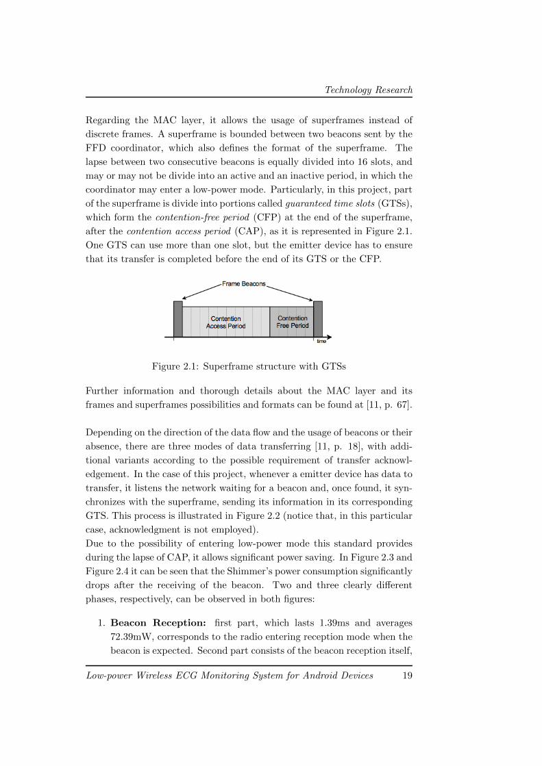
Technology Research
Regarding the MAC layer, it allows the usage of superframes instead of
discrete frames. A superframe is bounded between two beacons sent by the
FFD coordinator, which also defines the format of the superframe. The
lapse between two consecutive beacons is equally divided into 16 slots, and
may or may not be divide into an active and an inactive period, in which the
coordinator may enter a low-power mode. Particularly, in this project, part
of the superframe is divide into portions called guaranteed time slots (GTSs),
which form the contention-free period (CFP) at the end of the superframe,
after the contention access period (CAP), as it is represented in Figure 2.1.
One GTS can use more than one slot, but the emitter device has to ensure
that its transfer is completed before the end of its GTS or the CFP.
Figure 2.1: Superframe structure with GTSs
Further information and thorough details about the MAC layer and its
frames and superframes possibilities and formats can be found at [11, p. 67].
Depending on the direction of the data flow and the usage of beacons or their
absence, there are three modes of data transferring [11, p. 18], with addi-
tional variants according to the possible requirement of transfer acknowl-
edgement. In the case of this project, whenever a emitter device has data to
transfer, it listens the network waiting for a beacon and, once found, it syn-
chronizes with the superframe, sending its information in its corresponding
GTS. This process is illustrated in Figure 2.2 (notice that, in this particular
case, acknowledgment is not employed).
Due to the possibility of entering low-power mode this standard provides
during the lapse of CAP, it allows significant power saving. In Figure 2.3 and
Figure 2.4 it can be seen that the Shimmer’s power consumption significantly
drops after the receiving of the beacon. Two and three clearly different
phases, respectively, can be observed in both figures:
1. Beacon Reception: first part, which lasts 1.39ms and averages
72.39mW, corresponds to the radio entering reception mode when the
beacon is expected. Second part consists of the beacon reception itself,
Low-power Wireless ECG Monitoring System for Android Devices 19
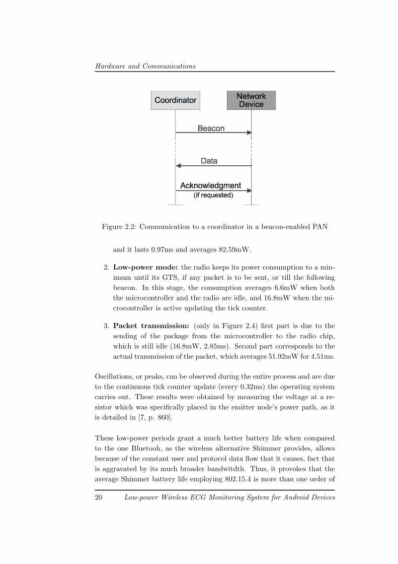
Hardware and Communications
Figure 2.2: Communication to a coordinator in a beacon-enabled PAN
and it lasts 0.97ms and averages 82.59mW.
2. Low-power mode: the radio keeps its power consumption to a min-
imum until its GTS, if any packet is to be sent, or till the following
beacon. In this stage, the consumption averages 6.6mW when both
the microcontroller and the radio are idle, and 16.8mW when the mi-
crocontroller is active updating the tick counter.
3. Packet transmission: (only in Figure 2.4) first part is due to the
sending of the package from the microcontroller to the radio chip,
which is still idle (16.8mW, 2.85ms). Second part corresponds to the
actual transmission of the packet, which averages 51.92mW for 4.51ms.
Oscillations, or peaks, can be observed during the entire process and are due
to the continuous tick counter update (every 0.32ms) the operating system
carries out. These results were obtained by measuring the voltage at a re-
sistor which was specifically placed in the emitter node’s power path, as it
is detailed in [7, p. 860].
These low-power periods grant a much better battery life when compared
to the one Bluetooh, as the wireless alternative Shimmer provides, allows
because of the constant user and protocol data flow that it causes, fact that
is aggravated by its much broader bandwitdth. Thus, it provokes that the
average Shimmer battery life employing 802.15.4 is more than one order of
20 Low-power Wireless ECG Monitoring System for Android Devices
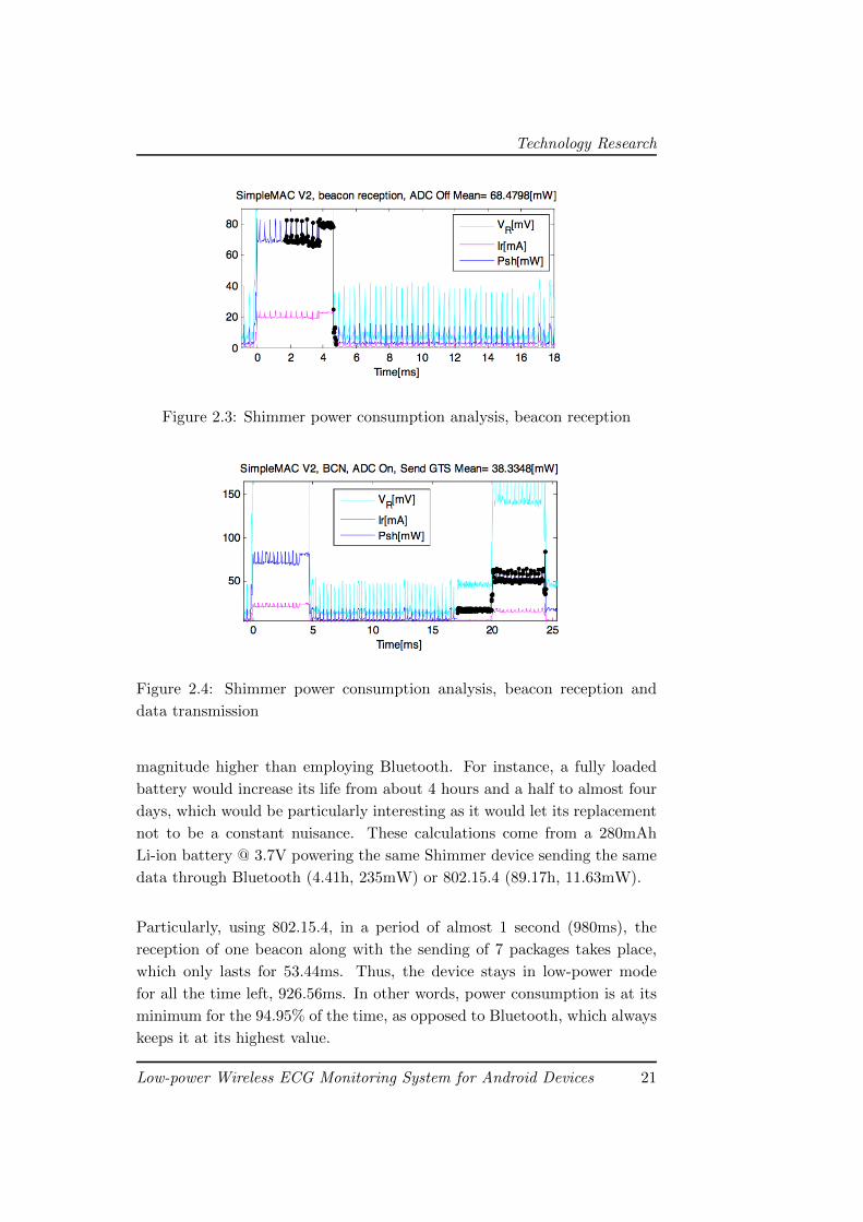
Technology Research
Figure 2.3: Shimmer power consumption analysis, beacon reception
Figure 2.4: Shimmer power consumption analysis, beacon reception and
data transmission
magnitude higher than employing Bluetooth. For instance, a fully loaded
battery would increase its life from about 4 hours and a half to almost four
days, which would be particularly interesting as it would let its replacement
not to be a constant nuisance. These calculations come from a 280mAh
Li-ion battery @ 3.7V powering the same Shimmer device sending the same
data through Bluetooth (4.41h, 235mW) or 802.15.4 (89.17h, 11.63mW).
Particularly, using 802.15.4, in a period of almost 1 second (980ms), the
reception of one beacon along with the sending of 7 packages takes place,
which only lasts for 53.44ms. Thus, the device stays in low-power mode
for all the time left, 926.56ms. In other words, power consumption is at its
minimum for the 94.95% of the time, as opposed to Bluetooth, which always
keeps it at its highest value.
Low-power Wireless ECG Monitoring System for Android Devices 21
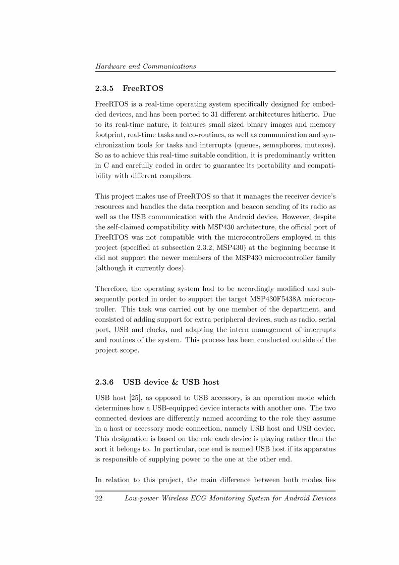
Hardware and Communications
2.3.5 FreeRTOS
FreeRTOS is a real-time operating system specifically designed for embed-
ded devices, and has been ported to 31 different architectures hitherto. Due
to its real-time nature, it features small sized binary images and memory
footprint, real-time tasks and co-routines, as well as communication and syn-
chronization tools for tasks and interrupts (queues, semaphores, mutexes).
So as to achieve this real-time suitable condition, it is predominantly written
in C and carefully coded in order to guarantee its portability and compati-
bility with different compilers.
This project makes use of FreeRTOS so that it manages the receiver device’s
resources and handles the data reception and beacon sending of its radio as
well as the USB communication with the Android device. However, despite
the self-claimed compatibility with MSP430 architecture, the official port of
FreeRTOS was not compatible with the microcontrollers employed in this
project (specified at subsection 2.3.2, MSP430) at the beginning because it
did not support the newer members of the MSP430 microcontroller family
(although it currently does).
Therefore, the operating system had to be accordingly modified and sub-
sequently ported in order to support the target MSP430F5438A microcon-
troller. This task was carried out by one member of the department, and
consisted of adding support for extra peripheral devices, such as radio, serial
port, USB and clocks, and adapting the intern management of interrupts
and routines of the system. This process has been conducted outside of the
project scope.
2.3.6 USB device & USB host
USB host [25], as opposed to USB accessory, is an operation mode which
determines how a USB-equipped device interacts with another one. The two
connected devices are differently named according to the role they assume
in a host or accessory mode connection, namely USB host and USB device.
This designation is based on the role each device is playing rather than the
sort it belongs to. In particular, one end is named USB host if its apparatus
is responsible of supplying power to the one at the other end.
In relation to this project, the main difference between both modes lies
22 Low-power Wireless ECG Monitoring System for Android Devices
Description
within the direction the power supply follows or, more specifically, the role
the Android running device adopts: Android device acts as host in USB
host mode, whereas it acts as device in accessory mode. However, there
is no difference in data transfer between them, as it remains bidirectional
in both modes. It is typical for the device with larger power consumption
(usually the Android device) to act as the USB host since it probably has a
power source of any kind, although this is not always this way.
In addition, when a device acts in USB host mode, creating the connection,
that is, instantiating and initializing the proper sockets, between both ends
is its responsibility, along with notifying the other end about the establish-
ment of the communication. On the other hand, the process that the device
role assuming system has to carry out is quite simpler, as it just consists of
checking the availability of the previously created communication.
Regarding this project, this matter applies in the way both the Android and
the receiver devices are connected and which one assumes the USB host role.
It would result particularly desirable that the Android device acted as host
so that the receiver could be fed from its battery (which would make the
collection really portable, non-dependent on the accessory power source).
However, it depends on the specific platform that this arrangement can be
possible.
Although certain Android devices running version 2.3 were capable of offer-
ing USB host support, this version only officially supports USB accessory
mode; whereas USB host mode is only available by default since version 3.1.
Thus, in order to get the required behaviour the usage of one of this special
devices or, preferably, a device running a 3.1 Android version or newer.
2.4 Description
The hardware related investigation is the main section of the research part
of the project. Not that there wasn’t any research involved in other areas,
but some critical elements of this part had never been researched before. At
the beginning of the project specific objectives were established and main
milestones elected, but absolutely no clue or direction for most of those mile-
stones was available. Moreover, in some cases the feasibility of the proposed
goals was unknown. Specifically the achievement of the very important ob-
jective of USB communication between an MSP430 and an Android powered
Low-power Wireless ECG Monitoring System for Android Devices 23
Hardware and Communications
device assuming the latter the role of master and acting the former as a slave
was something not done before and therefore no information was available
even in the Texas Instrument support site.
This whole development and research poses some quite interesting challenges
as it involves working nearly at every abstraction layer present on device
development, ranging from schematic capture and PCB design to operating
system related development. The main issues to be resolved are:
• 802.15.4 radio reception: data packets are emitted from the mon-
itoring ShimmerTMand are to be received and dealt by the accessory.
In order to do so, FreeRTOS has to be equipped with a working im-
plementation of the radio stack, which involves implementing part of
ZigBee’s MAC layer, described by IEEE 802.15.4, as it is the underly-
ing standard which the emitter nodes are based on.
• MSP430 USB handling: just as the radio stack, FreeRTOS is not
prepared to make use of the USB interface with which the MSP430
board –namely TS430PZ100USB– is equipped. Thus, it is necessary to
add the essential code in order to incorporate this functionality to the
OS. This issue, in the same way as the previous one, is a critical part
for the system to work properly since it may likely be a source of errors
unless it is perfectly made –for instance, it could add transmission lags,
packet corruption or even full package losses–.
• MSP430-Android communication: this issue is particularly rele-
vant as no project has ever claimed to feature this kind of connection
before. Hence, it means an additional challenge to be overcome since
it will involve the modification or complete development of an specific
driver for the MSP430-equipped device. This challenge is imposed by
choosing the USB host alternative so that the Android device powers
the accessory. On the other hand, USB device may ease this issue due
to the already resolved communication system with accessories made
by Google, yet it implies the accessory will need an additional power
source. Fortunately, it finally turned out not to be so tough as it was
expected and the goals related to this issue were successfully fulfilled,
as it can be read at subsection 2.5.2, MSP430 for Android USB Host
Comunication.
Over the following lines within the next section, the aforementioned chal-
lenges are detailed in the context of their own development stages. In addi-
24 Low-power Wireless ECG Monitoring System for Android Devices
Milestones
tion, objectives and results of each one of these stages are also presented.
2.5 Milestones
Due to the fair amount of time a essentially researching work like this hard-
ware development requires, the foreseen schedule is subject to changes which
may completely alter it regardless of how irrelevant they may seem, and thus
avoid the success of the project.
Keeping this risk in mind, the hardware development is planned as a se-
quence of milestones, ordered by increasing complexity. Every milestone
introduces a new technology, each one of them capable of covering the needs
of the project in a more complete way. In other words, the previously pre-
sented issues are to be resolved as these stages are overcome.
The schedule, then, starts with the usage of the Google Open Accessory
Development Kit, based on Arduino, in order to make a prototype as first
approach and, in this way, be able to parallelize software and hardware de-
velopment –notice that both of them depend on each other–. This choice
is made because of the well-known soft learning curve Arduino presents as
well as the already prepared connection the Google ADK provides between
accessories and Android devices.
The next step in the development, once the application has been proven to
communicate with a data-providing accessory, consists of making Android
capable of detecting and communicate via USB with an MSP430-equipped
device. This stage can be qualified as very critical, since almost every part
of the development depends on it.
The following milestone arises as a consequence of the FreeRTOS port which
was specified before: its target device, namely MSP430F5438A, does not
support USB communication, and by extension the port itself. Thus, the
work for this stage consists of providing FreeRTOS with USB support, which
is to be employed with the new target device, MSP430F6638, which is mem-
ber of the MSP430F66xx family with highest performance, along with USB
support.
Next, the planning sets the development of the communication between the
emitter nodes and the device. The previously existing FreeRTOS port al-
Low-power Wireless ECG Monitoring System for Android Devices 25
Hardware and Communications
ready supports the IEEE 802.15.4 standard MAC layer, so the work in this
milestone involves modifications in order to get the port to work properly
with the new MSP430F6638 platform. Although the first versions of the
schedule considered this next step at the same time of the previous one, in
later revisions it was decided to keep them separated for the sake of the
stability derived from isolating both developments.
Due to the division between the two previous stages, both developments,
USB and radio stacks, are to be done separately. In order to resolve the
likely communication problems this decision can cause, the next iteration
the planning considers is reserved for validating and fixing their coexistence
may provoke.
Finally, the schedule adds two extra stages: the first, which may be dropped
due to eventualities, considers the design of a miniaturized version of the
receiver device so as to dispense with the TS430PZ100USB board, which is
rather big and little portable. The second one is essential as it is reserved
for possible needed fixings and refinements.
All these stages are now detailed over the following subsections.
2.5.1 Arduino for Android USB Device Comunication
The objectives for this first milestone objectives are:
• acquire a suitable Android device prototyping environment,
• manage correct communication between Android and a prototype de-
vice, and
• develop an application emulating desired behaviour.
This milestone is set upon the consideration that it is a good approach in
order to familiarize the team with communications between Android and
USB devices. It also comes motivated by the previously supposed effort
the connection between Android and an MSP430-equipped device involves,
since it has not been done before as well as Android USB host mode support
has been out for only two months.
The process involved in the procurement of each objective is exposed next.
26 Low-power Wireless ECG Monitoring System for Android Devices
Milestones
1. Acquire a suitable Android device prototyping environment
The first step in order to develop this USB device consists of looking
for a platform which is able to provide the needed components and li-
braries so as to make the connection with Android feasible. Although
several devices are available to serve as Android accessories (as it is
explained at subsection 2.3.1), Google ADK is the chosen one since it
is based on Arduino: a considerable amount of libraries and documen-
tation is to be expected. Particularly, USB host mode library is the
main reason for choosing it.
2. Manage correct communication between Android and a prototype de-
vice
Once the target platform is chosen, the next step to be done consists
of developing some test firmware for the Arduino as well as modifying
consistently the Android application so that a proper communication
between both devices can be established and proven. A period of
learning and adaptation is required for the team to achieve this.
3. Develop an application emulating desired behaviour
For this milestone to be fulfilled, it is required that the firmware devel-
oped for the Arduino can emulate the behaviour of an actual sample-
receiving device. Thus, the microcontroller board is programmed in
order that it sends formatted data as the Android application is ex-
pecting to receive. In this way, it is visually verifiable that the data
transmission is performing properly.
Although Google refers its ADK as an accessory developing platform, it is
noticeable that it is in fact used as a prototyping tool, and hence this devel-
opment is not to be employed as a part of the final state of the system. As
opposed to this, this stage of the project is considered as training transition
to more technical developments to be engaged later.
2.5.2 MSP430 for Android USB Host Comunication
Objectives for this stage are:
• supply MSP430 with USB protocol application functionality,
• research Android USB protocol related functionality,
• make Android OS recognize MSP430 when plugged, and
• manage communication between Android and MSP430 via USB.
Low-power Wireless ECG Monitoring System for Android Devices 27
Hardware and Communications
Due to the need of USB support, both the microcontroller and its board
models are required to be as new as possible, since older models lack this
feature. Therefore, the MSP430F6638 microcontroller as well as the MSP-
TS430PZ100USB board are selected for this development, as it is explained
at subsection 2.3.2, MSP430.
Prototyping with Arduino during the previous milestone constitutes the
preparation for the development to be done in the present one. Yet, whereas
Android and Google ADK are designed to interact with one another, An-
droid is not prepared for supporting a device like an MSP430 out of the box.
So, in order to communicate both devices, an API from Texas Instruments
[26] is the only available tool, though it is designed for Windows OS.
Among all the contents the TI API includes, its examples result particu-
larly useful for the project requirements. Concretely, examples about CDC
(Communications Device Class) protocol set the needed basis to fulfill the
objectives for this milestone. Nonetheless, several examples does not seem
to function, not even in Windows, its target operating system. Thus, the
next step consists of studying both the examples and documentation from
TI so as to fulfill the objectives.
1. Supply MSP430 with USB protocol application functionality
As it was previously said, TI API contains a huge amount of informa-
tion in the shape of:
• Extense documentation: about the API itself and features of
TI devices.
• Sample Windows Applications: made to communicate Win-
dows PCs with external devices or enumeration tools.
• Suite of examples: each of them implements a combination
or one of the following USB protocols: Communications Device
Class (CDC), Human Interface Device (HID) or Mass Storage
Class (MSC).
The same problems, though, keep these examples from working with
the target MSP430 device. As a result of an intense investigation the
trouble is found to lie within one of the device’s clocks which, according
to the API documentation, may need an specific tuning –particularly,
4MHz–. Moreover, in spite of the fact that the board seems functional,
28 Low-power Wireless ECG Monitoring System for Android Devices
Milestones
it actually lacks that certain clock. As expected, TI example properly
works with the addition of the 4MHz clock.
In addition to the previous hitch, another one arises upon changing
the current workstation. Every work during this development is car-
ried out within a Windows virtual machine running over Windows,
yet the examples stops working when the host machine is changed for
another one running GNU/Linux, particularly Ubuntu. Despite hav-
ing achieved the present objective, this fact reduces the expectations
for the next one since Android, the target OS, is also based on Linux
kernel.
2. Research Android USB protocol related functionality
As it is expected because of its performance with Ubuntu, Android is
not able to recognize the target device, and hence the example cannot
be tested. In order to solve this inconvenience, two solutions are con-
sidered: search for the proper driver, if any, and modify it or develop
it from scratch.
Nevertheless, the search concludes with no results, so it is assumed
that this particular driver does not exist. The most similar resource
found consists of a driver for MAC OS X, which would have to be
consistently modified in order to make it work. However, this idea
is dropped due to the advice obtained from a qualified source that
suggests exploring other methods to make the communication feasible
apart from developing a driver, which may be too harsh and require
too much time. A quite considerable risk is assumed by doing so as
there are no warranties of finding a proper solution.
Fortunately, further research drives to a successful alternative: it is
found that Android actually implements HID protocol, which is also
supported by MSP430 through the Texas Instruments API. Finally,
upon loading the proper HID application into the MSP430 from the
TI API this objective reaches its fulfillment.
3. Make Android OS recognize MSP430 when plugged
Once both two first objectives of this milestone are achieved, MSP430
Low-power Wireless ECG Monitoring System for Android Devices 29
Hardware and Communications
recognition by Android is inmediate when the connection is set since
all the needed work is already done.
4. Manage communication between Android and MSP430 via USB
At this point, the work still to be done consist of modifying the An-
droid application in order that it can read data from the receiver de-
vice. However, this is not a trivial work as Android USB host commu-
nication is highly dependant on the device which it has to read from.
Thorough investigation over the API manuals is required to discover
every detail and make it work.
Therefore, as it can be deduced from the previously explained happenings,
this stage draws a great amount of risk to the hardware development due to
several critical points it involves which further required tasks are to be based
on. In other words, part of this project’s probabilities of success greatly de-
pends on the feasibily of the present objectives, so this milestone completely
conditions the planning. Once it is finished, it certainly allows to tune the
schedule with better accuracy.
2.5.3 USB in FreeRTOS
This milestone’s objectives are:
• check the proper working of FreeRTOS with the new microcontroller,
• validate the feasibility of the usage of USB API along with FreeRTOS
in MSP430,
• correctly integrate USB API into FreeRTOS, and
• manage USB data sending in FreeRTOS.
Despite having already achieved communication between Android and an
MSP430 device through USB, there is still work about this since it is only
a test version which does not take FreeRTOS into account. In fact, FreeR-
TOS, as it is explained at subsection 2.3.5, will be responsible of managing
the operation of the microcontroller in addition to the radio. So, adapting
the USB functionality and equipping FreeRTOS with it arises as the next
relevant stage of the project, required to make the receiver device possible.
30 Low-power Wireless ECG Monitoring System for Android Devices
Milestones
1. Check the proper working of FreeRTOS with the new microcontroller
Prior to starting with this milestone’s core objective, FreeRTOS needs
to be adapted in order to make it work with the new microcontroller,
namely MSP430F6638, since it is addressed to a different model, the
MSP430F5438A. This change implies the modification at several points
of the code of the operating system so that its proper working can be
assured.
2. Validate the feasibility of the usage of USB API along with FreeRTOS
in MSP430
The following objective to be achieved consists on incorporating the
TI USB API to FreeRTOS, focusing in its completion rather than its
perfect working. This is not a trivial task due to the large extension
of API’s code. Furthermore, The most relevant inconvenience that
endangers this work is the considerable amount of resources which are
found to be in mutually exclusive condition, such as microcontroller
pins and clocks. However, this is a matter of properly balancing the
distribution of these resources over time, and thus it can be achieved
by paying special attention and care to it.
3. Correctly integrate USB API into FreeRTOS
Although the USB API is already functional and integrated into FreeR-
TOS, this integration is made without caring about keeping the com-
patibility with already supported microcontrollers, and hence losing
this feature. Therefore, the next step consists of restoring its support
for other devices like MSP430F5438A. Nonetheless, as the original
FreeRTOS port already supported different devices such as the one
mentioned and ShimmerTM, this work is not as hard as it should be if
carried out analogously.
4. Manage USB data sending in FreeRTOS
Once the USB functionality is properly integrated into FreeRTOS, it
is required to check whether the communication it provides correctly
stablishes and the trasmitted data does not suffer from corruption or
loss. The method used to test this consists of running a special pro-
gram on FreeRTOS which sends a known character sequence so the
input and output sequence can be checked as equal. As they are, in
Low-power Wireless ECG Monitoring System for Android Devices 31
Hardware and Communications
fact, the same sequence, this objetive along with the entire milestone
are fulfilled.
With the work carried out during this stage, communication between the re-
ceiver and the Android device is completed, fact that limits the work that is
left to to the management of the wireless reception through 802.15.4. Wire-
less communication will be dealt over the following two milestones.
2.5.4 802.15.4 in FreeRTOS
This milestone’s objectives are:
• validate current implementation of 802.15.4 in FreeRTOS on the MSP430
testing board,
• manage connection to the CC2420 radio module to the target MSP430
device,
• port implementation of 802.15.4 to the target MSP430 device, and
• prepare such implementation for actual usage.
The next step is the achievement of wireless 802.15.4 receiving in the MSP430
board through the CC2420 radio module. An existing port of the MAC layer
for the FreeRTOS running in the MSP430 is taken as the starting point. The
main advantage of employing it is that it’s the same code running in the
802.15.4 emitter utilized in the project. In any case, before actual usage
a correct validation of the software is mandatory. Once validation is com-
pleted, the MAC layer is to be implemented into the target MSP430 device
and tweaked for actual usage. That is the ultimate goal of this milestone.
1. Validate current implementation of 802.15.4 in FreeRTOS on the MSP430
testing board
Before addressing the delicate task of implementing the 802.15.4 MAC
layer port into the target MSP430 device, validation of this port is
conducted in the testing MSP430F5438A board. This decision is mo-
tivated by the fact that this board provides serial port output and out
32 Low-power Wireless ECG Monitoring System for Android Devices
Milestones
of the box CC2420 connection.
The testing of the MAC layer provides negative results, as although
802.15.4 receiving functionality is present in the port, the OS is not
actually notified about it and the received data is lost. Moreover,
problems in the receiving of packages of maximum size, which are the
ones sent by the 802.15.4 emissor, are also detected.
The amendment of the aforementioned problems takes no longer that
expected, and the porting of the 802.15.4 support to the target MSP430
device begins. The original developer of both the FreeRTOS port and
the MAC layer is notified about the detected problems, and the fixes
are also implemented on the 802.15.4 emissor.
2. Manage connection to the CC2420 radio module to the target MSP430
device
The target MSP430PZ100USB board provides no CC2420 radio mod-
ule connection socket, so the port of the validated 802.15.4 module to
this board requires manual connection handling of the radio device.
The MSP430 features a 100-pin footprint, and a complete study of all
the 100 pins target usage and on-board availability becomes manda-
tory for the identification of the pins that the CC2420 will be connected
to. Special care is put to avoid collisions between the USB and the
radio modules regarding hardware resources.
Successful identification of the required pins done, a manual soldering
of the CC2420 radio module is executed and subsequent testing can
continue.
3. Port implementation of 802.15.4 to target MSP430 device
The inclusion of the 802.15.4 MAC layer into the target MSP430 device
involves modifing the FreeRTOS pin mapping code, which is a specially
sensitive task. The code is carefully modified taking the mapping code
for the already tested MSP430F5438A as the base. Special care is put
Low-power Wireless ECG Monitoring System for Android Devices 33
Hardware and Communications
in the task as any mistake would cause the radio module to fail at ini-
tialization and following error tracking would be very time consuming.
Once the FreeRTOS pin mapping is complete, no further work is, ini-
tally, required in the port process.
4. Prepare 802.15.4 implementation for actual usage
Having both the hardware and the software part of the 802.15.4 mod-
ule port completed, actual testing is conducted on the target MSP430
device, resulting in an initial absolute failure. The radio module nor
even turning on, an in-depth research on the subject becomes the main
priority.
The solution is found in one of the TI code examples for the tar-
get MSP430, which provides a different code for the Universal Re-
ceiver/Transmitter (USART) initialization routine than the one em-
ployed in the testing MSP430F5438A. Substitution of this code in the
FreeRTOS implementation solves the problem and further testing in-
dicates that the radio module implementation has concluded.
The rest of the milestone allotted time is then employed in final test con-
ducting resulting in small changes to the code to fully adapt it for the project
needs but no critical changes are required. By the end of the milestone time
a fully functional 802.15.4 module is achieved in the target MSP430 device,
although actual validation of the correct coexistence of the radio and USB
modules is to be conducted in the next project phase.
2.5.5 802.15.4 & USB coexistence under FreeRTOS
This milestone’s objectives are:
• assess conflict-free coexistence of current implementation of both USB
and 802.15.4 modules in MSP430, and
• manage sending data received from 802.15.4 via USB.
34 Low-power Wireless ECG Monitoring System for Android Devices
Milestones
Having both the USB communication and the 802.15.4 receiving working
over FreeRTOS when isolated, the next task assumed is the testing of them
both working together. While they should theoretically coexist without con-
flicts, the manual mapping of the processor pins performed in the last mile-
stone involves a risk this won’t happen. Once such hardware validation has
concluded, software validation is also to be conducted by the development
of a first version of the USB sending program.
1. Assess conflict-free coexistence of current implementation of both USB
and 802.15.4 modules in MSP430
As said, resource sharing conflicts are bound to occur when joining
the radio and the USB modules. The possibility of hardware related
conflicts being known when developing each module, special care is
put in the selection of resources for them both. The testing conducted
in this phase confirms the successful outcome of these task, as no real
hardware conflicts arise.
For software conflict testing the decision is made to validate directly
against an actual application featuring part of the functionality re-
quired in the final receiver. That testing process is then merged with
the work required for the next milestone objective.
2. Manage sending data received from 802.15.4 via USB
For the achievement of this objective, an application is developed with
functionality to send the byte sequences received from the CC2420 ra-
dio module via USB employing the HID protocol. Software resources
sharing between both modules is confirmed to be conflict-free, con-
cluding the validation of the correct coexistence of them both, yet a
specific problem is found to occur.
The real-time sending speed of the 802.15.4 emissor and the limited
storage capacity of the CC2420 radio module, as well as delays caused
in the processing involved in USB data sending, are found to be caus-
ing the loss of data packages. The solution is twofold: on one hand,
and regarding the 802.15.4 emissor device, the package emission is
stretched to employ the whole available time slot, instead of sending
Low-power Wireless ECG Monitoring System for Android Devices 35
Hardware and Communications
all the data as fast as possible at the beginning. On the other hand,
a buffering system is implemented in the receiver device to allow the
constant processing of arrived data when a package is currently being
sent via USB.
The described solution removes the problem and the objective is, thus,
accomplished. Moreover, full required functionality for the receiver de-
vice is implemented.
Before the finalization of the milestone some final testing is conducted with
positive results. The 802.15.4 receiver device is capable of sending data
received form the radio following the 802.15.4 standard through the USB
connection. This allows the beginning of actual accessory development with
the objective of obtaining a small PCB, closer to an actual product than the
MSP430 equipped board.
2.5.6 MSP430 based device design
The objectives for this milestone are:
• exhaustive analysis of the reference board,
• capture of the board schematic, and
• design and routing of the actual PCB.
At this point the objective of the hardware research part of the project
has already been achieved. An MSP430 based 802.15.4 USB receiver has
been developed and tested. It is able to connect to an Android device and
draw power from it, and little power is required. Low power requirements
achieved, the next step is the miniaturization of the board so as to minimize
the size of the system. Production of a small device which can be attached
to the Android system is the objective of this milestone.
1. Exhaustive analysis of the reference board
The device board design is to be made taking the MSP-TS430PZ100USB
board as a base, as it provides all the components required by the
36 Low-power Wireless ECG Monitoring System for Android Devices
Milestones
target device and the schematics are available as part of the official
Texas Intruments provided documentation. The first step towards the
achievement of the low sized device is the correct identification of the
minimum set of components required by the target functionality, as
not every component present in the base board is actually used. This
is so because the TS430PZ100USB is an evaluation board providing a
lot of features targeting the simplicity of the prototyping process.
In order to minimize the size of the board, three main modifications
are conducted. First, power source selection related circuitry is re-
moved and the board is left with just the ability to get power from the
USB connection. This eliminates a number of power source selection
jumpers and voltage regulation components. Second, a meticulous se-
lection of the processor pins which will be available for external usage
is performed. This selection tries to balance between minimizing the
number of pins exposed and as featuring as much expansion capabil-
ities as possible. The final set includes, apart from the pins required
by the radio and USB modules as well as power related ones, the eight
pins required for one of the IO ports, one pin intended for the connec-
tion of a led and one for the inclusion of a reset switch.
The other main change to the original board is the inclusion of the
connection sockets for the CC2420 and the substitution of the debug-
ging JTAG port for a smaller one, which will require the production
of a standard JTAG cable adaptor but will also reduce the size of the
board significantly.
Once the selection of components is validated, the production of the
schematic of the new board begins.
2. Capture of the board schematic
The design of the board schematic is the next step towards the obten-
tion of the actual PCB for the device. The schematic capture process is
done from scratch, even if the board is based on the TS430PZ100USB,
because no usable schematic file for the evaluation board is found. The
device circuitry being simple, the main problem source for this task
Low-power Wireless ECG Monitoring System for Android Devices 37
Hardware and Communications
is the selection of as small as possible footprints for the board com-
ponents, and further implementation into the design software. Some
of these footprints are obtained from trusted sources, and other, more
obscure ones, are to be made by hand. This footprint selection process
is very important, as will be the foundation of the PCB design stage.
Once the schematic is finished and validated, a first prototype is to
be built for actual testing. Prior to this, the development of the bill
of materials of the device is performed, focusing in minimizing the
total cost while acquiring the as small as possible, specifically choosen
footprint featuring componets.
3. Design and routing of the actual PCB
In order to start the design of the miniaturized receiver, validation of
the proper operation of the developed prototype is mandatory. As it
can be expected, minor mistakes may be made in both the schematic
capture and the prototype building which may make the final product
does not work once built. In fact, avoiding such kind of failures is the
purpose of the prototype.
Once the test of the prototype is completed, the designing process
just consists of finding a proper location for each one of the previously
identified components. This task entails several risks since the design
is subject to changes, changes which, however small they are, may
lead to a complete redesign of the device. Hence, special care has to
be devoted to this job so as to avoid significant waste of time.
As for the PCB routing, special attention has to be paid so that the
actual routing is as similar as possible to the planned one, and hence
less time is to be dedicated to the correction of the circuit tracks. In
addition, assuring each component has enough space, tracks are not
overlapped and power lines are wide enough to guarantee the correct
voltage are also critical tasks.
Assuming this guidelines are followed, PCB routing becomes feasible
and gets done with no additional problems, so the building of the de-
vice is ordered.
38 Low-power Wireless ECG Monitoring System for Android Devices
Closure
In the absence of a thorough testing of this miniaturized version of the re-
ceiver device, which is set to be done during the next stage of the project,
the miniaturization process is successful and a significantly smaller version
is obtained. In particular, its dimensions are 61 x 32 x 6 mm without an-
tenna, 61 x 32 x 35 mm with antenna, as opposed to the measures of the
prototype 72.5 x 63.5 x 35 mm and the training board, considerably larger.
These smaller dimensions play a determinant role both in the adoption and
usefulness of the device.
2.5.7 Final Validation and Release Candidate Version
The following tasks are to be completed within this last stage of the devel-
opment:
• Validate the final version of the receiver device, and
• fix possible errors.
Tests are to be driven with the recently built receiver device in order to
assure its proper operation, capability of being programmed as well as its
correct behaviour when carrying out its tasks within the whole system. Due
to the thorough previous tests and revisions its design and its predecessors
(both the training board and the mockup) have passed, little or no bugs are
expected to be found. Even though, this task is focused on checking so as
to avoid unexpected behaviours or malfunction with the last version of the
receiver.
Fortunately, thanks to the meticulous process that has been conducted to
avoid unforeseen failures, the final device works flawlessly, except for few
minor fixes quickly resolved.
2.6 Closure
The hardware part of the project has successfuly achieved the objective of
the production of an 802.15.4 USB receiver. This device provides all ex-
pected functionality, specifically the transferring of data received from the
Low-power Wireless ECG Monitoring System for Android Devices 39
Hardware and Communications
802.15.4 radio module via USB acting as the slave device in the USB connec-
tion, drawing its power from the master device. This master device can be
any system with an implementation of the HID protocol, and the produced
device has been tested as an 802.15.4 receiver both for an Android device
and a Windows based computer. Moreover, taking an evaluation board as
the starting point, the device has been custom designed and produced, and
miniaturization has been conducted so as to be built into a printed circuit
board, even if actual production of such PCB has been initialized but not
yet finished.
The fact that the 802.15.4 USB receiver is independent from the domain of
the project, i.e. it only assumes the task of sending through an USB connec-
tion the data received through the radio, it does not analyize or processes the
data, makes it a fully functional general purpose 802.15.4 receiver. Function-
ality for data sending through 802.15.4 is present in the device, both in the
software and hardware layers, but it lacks the code to send data received from
USB to the radio. Nevertheless, this functionality can be implemented with
ease, thus turning the device in a full fledged 802.15.4 USB emitter/receiver.
In the specific scope of the project, the application of the device for the
receiving of the ECG wave data, due to its small size and low battery re-
quirements, leads to a more comfortable employment of the monitoring sys-
tem. Even if the necessity of employing an Android accessory decreases the
portability of the system when compared to the utilization of the Bluetooth
module, which is embedded in the Android device, the order of magnitude
lower battery requirements compensate throughout, as the lifetime of the
battery of the ECG delineator node when using 802.15.4 is increased from
hours to days.
In conclusion, all the objectives of the hardware research and production
have been achieved in the deadlines set for the project, even when coping
with the uncertainty inherent to any research and sharing resources with the
parallel-conducted software development. Moreover, additional objectives
has been pursued and also realized, like the development and miniaturization
of the custom board, making this hardware project a success.
40 Low-power Wireless ECG Monitoring System for Android Devices
Chapter 3
Software Development
3.1 Introduction
The development of a software ECG display application targeted at Android
Operating System for mobile devices is the counter-part to the hardware re-
search part of the project. This application is to substitute the already
developed one for iOS devices, adding funcionality extracted from feedback
obtained for that and including extra features which could not be imple-
mented in it. The software must provide functionality to visualize ECG
data from Bluetooth or 802.15.4 sources (the latter obtained via the 802.15.4
USB receiver developed in the hardware part of this project) in real-time,
as well as to save that data into file logs for afterwards reading.
Android as a development platform provides a wide set of high abstrac-
tion level tools to emphasize robust and reusable design for low resource
based, quick development cycles. Such benefits require the adequation of
the software design and architecture to the constrains imposed by the An-
droid development framework.
Given that none of the project team members had received any instruction
on this framework, engaging the development of an Android application
implies an important risk. Moreover, after the research and training steps
concluded, follow up of such risk can not be halted, as the quick, robust
software development is only assured when building an standard Android
application; dynamic, soft real-time functionality implementation is not dis-
couraged, but also not guaranteed to work. Mobile devices development
restrictions and common practices are also unknown to the team at the be-
41
Software Development
ginning of the project.
Even when the aforementioned eased development features are applicable,
mobile devices are harsh software environments due to, amongst others,
memory and battery constrains, where processes have to handle being sus-
pended by an incoming call or similar external events. This factors are
specially critical for an application as the one developed in this project,
which needs to continually parse and log data.
The application is also intended to act as a quick testing front-end for
the prototypes produced by the parallel-conducted hardware research. By
providing fully-functional application modules since early stages of devel-
opment, hardware prototypes could be best-case and worst-case checked
by directly connecting them to the Android device for data visualization.
Throughout the project process, visual verification has proven to be a very
effective method when working with large quantities of data which were
more easily checked against their visual representation than value-by-value
reading.
These factors lead to the adoption of an agile software development process
focusing on functionality building while prototyping more high risk involving
features. To avoid typical drawbacks of such methodologies, great emphasis
is put on the application of characteristics found in Iterative and Incremen-
tal processes, namely, use case driven and risk focused development. That
way, project scheduling is done addressing higher risks first while assuring
expected functionality to be implemented on time thanks to the use case
model.
3.2 Overview
In the following sections a complete view of the software development project
is presented, beginning with the requirements captured for the project and
a comprehensive description of the risk analysis process. The use case sce-
narios identified from the requisites will be detailed next, followed by an
explanation of the system design and architecture. Then, the development
process will be exposed in an exhaustive manner, and the chapter will finish
with a review of the software development project.
42 Low-power Wireless ECG Monitoring System for Android Devices
Requirements
3.3 Requirements
The requirement capture process for the project considers three main stake-
holders: the project directors, the EPFL and the UCM as the base project
developer parties and the project team members; and is done in two sessions.
The first one produces the basic requirement list which describes the system
and is used to schedule the earlier development iterations. This is so be-
cause of the strong time restrictions this software development project had
to cope with. When the critical functionality is achieved and the hardware
research reaches a suitable state, the second requirement capture session
is conducted. By then, the EPFL and UCM representative had shown the
state of the development to the stakeholder party of him, and collected feed-
back. Thus, the requirements produced by this second session are of a more
user-oriented nature.
The functional and non-functional requirement lists are presented next.
3.3.1 Functional Requirements
• R01 - Receive raw data via Bluetooth
• R02 - Receive raw data via 802.15.4
• R03 - Receive raw data from a log file
• R04 - Parse raw data into processed data
• R05 - Display processed data
• R06 - Log raw data
• R07 - Log processed data
• R08 - Scale View Vertically
• R09 - Scroll View Vertically
• R10 - Scroll View Horizontally
3.3.2 Non-functional Requirements
The following non-functional requirements are identified:
• The application must display ECG data at 30fps.
• The application must run on a Motorola Xoom device.
Low-power Wireless ECG Monitoring System for Android Devices 43
Software Development
3.4 Risk Analysis
Being the project mainly a hardware research project, and considering the
software development part of it useless without successful results on the
hardware part, a detailed process of risk analysis is mandatory to be con-
ducted since the earlier stages of planning and development so as to avoid
wasting manpower on futile work.
The risk list at the end of the project is as follows:
• PR1. Functionality of the application is inferior to that featured by
existing iOS application
• HR1. 802.15.4 receiver device delayed
• HR2. 802.15.4 receiver device unfeasible
• MR1. Mobile device unsuitable for target functionality
• AR1. Lack of instruction on Android development delays workflow
• AR2. Android providing subpar performance when handling required
data
• AR3. Android rendering capabilities unable to handle required data
This risk analysis focuses on two main risk sources: the parallel-conducted
hardware research, and Android as a development platform. Project defini-
tion and team related risks are also considered.
The hardware research part of the project delivers the highest probability
and impact rated risks. It is so because those risks are external to the soft-
ware development project scope and thus can not be handled by any of the
tools provided by any development methodology. At the same time, should
such risks come to be, the impact on the software product would be, in most
of cases, as catastrophic as turning the whole development useless thus caus-
ing its cancellation.
Regarding Android development only a subset of the final set of risks is as-
sessed at first. Every risk in this subset dealt with the team lack of knowledge
about the Android platform and was scheduled to be addressed foremost.
A last risk is added to this group after the first research on mobile devices
limitations regarding potential unfitness of such devices for near real-time
44 Low-power Wireless ECG Monitoring System for Android Devices
Risk Analysis
display and handling of not-so-small data packages. That risk handling plan
proves to be key to the successful outcome of the project as the remaining
subset of Android-related risks are linked to Android applications display
performance.
The usual project definition and personal risks such as incorrect deadline
scheduling or unability to reach critical milestones on time are also pon-
dered, increasing their impact rates as the application would be needed by
the hardware device to secure a successful outcome for the project.
A detailed view of each assessed risk is provided next, including risk evolu-
tion throughout the project lifetime.
PR1. Functionality of the application is inferior to that featured by exist-
ing iOS application
Probability: Moderate
Impact: Very High
Description: Failure to provide an expanded set of features in the Android
application when compared with the iOS application renders the software
part of the project invalid on its own. It could, then, only be valid as demo
software for USB receiver device showcasing. If the device is not finished,
then the whole software development project will have been futile. The key
marker for this risk is unability to generate valid software modules through-
out the development that provide required functionality. Failure to reach
milestones and use case realizations on time is other important marker.
Preventive measures are taken to avoid the occurence of this risk since the
beginning of the development by a functionality building focused project
scheduling for the first development phases.
This risk is marked as surpassed at the reviewing meeting of Iter-
ation 2 as all key functionality has been implemented, as planned.
HR1. 802.15.4 receiver device delayed
Probability: High
Impact: High
Description: Being the production of the 802.15.4 receiver device depen-
dent on the hardware research part of the project a delay on the estimated
milestones for that part of the project is likely to occur. Should that hap-
pen, hardware research and development will need to be prioritized over
Low-power Wireless ECG Monitoring System for Android Devices 45
Software Development
this software project. That could lead to big delays in software production.
To prevent the rising of further problems derived from those potential de-
lays, the software development process must always work with non-solid,
ready-to-change deadlines and milestones. Application functionality is to
be ranked in order of importance of implementation to be prepared, in case
of an unexpectedly big delay, to leave less important functionality out of
the scope of the project. Markers to be followed up are: unsuccessful out-
put from hardware research (a new branch of the potential technologies
tree has to be explored), failure to reach hardware development or research
milestones and delays in the acquisition of tools or devices needed for the
hardware project. Preventive measures considered are: detailed follow up
of the hardware research development, reducing the software development
team if manpower is needed in the hardware area, and planning asuming
delays on component acquisition.
HR1 is monitored throughout the whole software development
project, and marked as surpassed at the reviewing meeting of It-
eration 5.
HR2. 802.15.4 receiver device unfeasibe
Probability: Medium
Impact: Critical
Description: Until hardware research results are successfully delivered
there is no guarantee of the viability of the 802.15.4 receiver device. This
software development project loses most of its value if such device is not
developed, as the iOS application already exists. Developing an Android
application with an equal feature set is also a valid objective, so this risk
does not render the development invalid: the full team will then work on
software development, and requirements will be restated to include more
final-user oriented functionality and/or features from the future set. This
risk can be monitored with the following markers: unsuccessful output from
hardware research and failure to reach hardware development or research
milestones. Being both external to this software project, no preventive mea-
sures can be applied apart from scheduling allowing smaller team sizes for
the software area.
The probability of the risk is reduced to low after the reviewing
meeting for Iteration 3, when the critical hardware research has
concluded with positive results. HR2 is marked as surpassed when
the production of a device prototype is finished and tested.
46 Low-power Wireless ECG Monitoring System for Android Devices
Risk Analysis
MR1. Mobile device unsuitable for target functionality
Probability: Low
Impact: Critical
Description: Even when mobile devices technical specifications have in-
creased significantly in the previous years, specially regarding CPU power
and rendering capabilities, the soft real-time requirements of the project in
terms of data manipulation and visual representation involve a low prob-
ability risk of the application being unsuitable for such devices. The risk
probability is decreased by the fact that similar featured applications exist
both for iOS and Android powered devices. Even so, the 802.15.4 receiver
device USB interface does not allow for this risk not to be reckoned. Pre-
ventive measures considered: quick prototyping of critical functionality to
discard unfeasibility, conduction of performance tests, both rendering and
data handling related, in the target device and testing of USB-Android com-
munication as soon as possible in the project schedule.
As performance tests are conducted on early builds of the appli-
cation, the need of further research on this risk arises as the data
handling performance in the target device is low, but not as low as
the rendering performance. Thus, this risk is unfolded into risks
AR2 and AR3, both related to Android performance when han-
dling the aforementioned tasks. This risk follow up is then halted,
as it is no longer needed.
AR1. Lack of instruction on Android development delays workflow
Probability: High
Impact: Moderate
Description: None of the team members has received any instruction on
Android development and throughout research is not viable because of time
restrictions. It is reasonable to foresee potential delays in the development
because of the parallel instruction-development flow, as well as the need
to rewrite parts of the system rendered obsolete when further knowledge
is acquired. Application malfunctioning, unexpected behaviours and low
performance are markers to be tracked. As a preventive measure a short
instruction time will be scheduled at the beginning of the project, but every
team member is responsible to continue his instruction throughout the whole
project. Application builds are to be checked for big differences against
canon Android applications behaviour.
The risk is marked as surpassed after Iteration 3, as critical func-
tionality has already been implemented and tested, though An-
Low-power Wireless ECG Monitoring System for Android Devices 47
Software Development
droid instruction is not halted.
AR2. Android providing subpar performance when handling required data
Probability: Moderate
Impact: High
Description: The benefits of the high-level, single application model pro-
vided by Android are such in behalf of the sacrifice of performance. In
this project soft real-time requirements are present, and the system needs
to process around 250 ECG wave samples [7] (among other data) per sec-
ond. Android code reutilization and class based programming suggested
practices, the absence of an explicit memory management API and the em-
ployment of the Garbage Collector only complicate the achievement of such
requirements. Special care will need to be put on the development and
performance checks are to be conducted regularly on generated builds to
ensure the avoidance of this risk. If evidence is found of Android inability
to provide the required perfomance (and there is no way of attributing the
failure to the team’s lack of ability), low-level Android development will be
considered. As the probability of this last scenario to occur is quite low, no
research will be conducted in low-level Android development until manda-
tory.
The risk is verified to be happening during Iteration 2 testing
phase. Lack of care on memory management is found to be the
problem, and is solved in Iteration 3. The risk is marked as sur-
passed after the review meeting for Iteration 4.
AR3. Android rendering capabilities unable to handle required data
Probability: Low
Impact: High
Description: The Android Operating System runs on quite a wide range
of devices, each with its own technical specifications. Providing the single
application development model that Android features requires many soft-
ware layers, many of them of high abstaction level. The risk exists, thus,
that the rendering required by the project could not be achieved within the
involved time restrictions. The target device for the project is fixed (see
section 3.3 Non-functional Requirements Subsection) as a Motorola Xoom.
This device employs a dedicated Tegra2 GPU [27] which should suffice, so
risk probability is chosen as low. Performance tests in the display module
are to be conducted, though, so as to make sure that a correct usage of the
available resources is being done. If low rendering performance is detected,
48 Low-power Wireless ECG Monitoring System for Android Devices
Use Cases
Android native level rendering API, Renderscript, is to be looked into as a
remedy, once the code is assured to be optimized.
Risk probability is increased to Moderate during Iteration 3 as low
performance is detected but is considered not critical enough to
apply the Renderscript solution. The risk is marked as surpassed
in the reviewing meeting of Iteration 4.
Thanks to this risk analysis the project schedule is developed in such a man-
ner that it prioritizes risk suppressing and the decision is made to plan only
the first two of the five intended development iterations, leaving the other
three as drafts to allow them to evolve at par with the uncancelled risks. Use
case realization order is also selected based on this risk analysis, ensuring
that higher risk involving features are developed (or at least prototyped) as
early as possible.
Use cases for the project are presented next, followed by the system architec-
ture description, to allow a finer understanding of the software development
project schedule and related decisions, which will be detailed in the next
section.
3.5 Use Cases
The project use cases are now presented following the use case common style
described by Martin Fowler [Fowler, 2004], as the relaxed template allows for
quicker document producing than more detailed descriptions such as those
presented by Cockburn [Cockburn, 2001].
Actor listing is omitted in all the descriptions, because of the following
implicits:
• The main actor for the use case is the user
• The only other actor is the data emitter node, when applicable. It
can refer to the Bluetooth emitter device or the USB 802.15.4 receiver
device.
Please note that the 802.15.4 emitter node is not considered an actor as the
communication with such device is handled by the USB 802.15.4 receiver,
which actually is the considered actor.
Low-power Wireless ECG Monitoring System for Android Devices 49
Software Development
3.5.1 UC1. View data from Bluetooth
Description The user wish to receive and visualize data from a Bluetooth
ECG node in real-time. He will start the communication, visualize real-time
received data and finish the connection once done.
This use case captures requisites R01, R04, R05, R06, and R07.
Preconditions The application is in the main menu screen.
Main flow
1. User indicates his will to start Bluetooth data visualization.
2. The system prompts for the node to connect to.
3. User specifies the desired node.
4. The system manages connection to the node. If unable to establish
the connection, see AF1.
5. The Bluetooth node sends data to the system.
6. The system shows processed data to the user. Received data is also
logged.
7. The user can now adjust view parameters (See UC4)
8. User chooses to finish data visualization.
9. The system closes active connections and stops data visualization.
10. The system returns to the main menu.
Alternative Flow 1 The system cannot establish connection to the Blue-
tooth node selected by the user.
1. The system notifies the user about the problem.
2. The system returns to the main menu.
50 Low-power Wireless ECG Monitoring System for Android Devices
Use Cases
3.5.2 UC2. View data from USB Receiver
Description The user wish to receive and visualize data from an 802.15.4
ECG node in real-time. He will start the communication, visualize real-time
received data and finish the connection once done. The data from the node
will be received via the USB 802.15.4 receiver device.
This use case captures requisites R02, R04, R05, R06, and R07.
Preconditions The application is in the main menu screen.
Main flow
1. User indicates his will to start USB receiver data visualization.
2. The system asks the user to connect the USB receiver.
3. User connects the USB receiver.
4. The system manages connection to the USB receiver. If unable to
establish the connection, see AF1.
5. The USB receiver device sends data to the system.
6. The system shows processed data to the user. Received data is also
logged.
7. User can now adjust view parameters (See UC4)
8. User chooses to finish data visualization.
9. The system closes active connections and stops data visualization.
10. The system returns to the main menu.
Alternative Flow 1 The system cannot establish connection to the USB
receiver device.
1. The system notifies the user about the problem.
2. The system returns to the main menu.
Low-power Wireless ECG Monitoring System for Android Devices 51
Software Development
3.5.3 UC3. View data from log file
Description The user wishes to read a log file created from a real-time
visualization session. He will specify the log file to load, visualize stored
data and finish visualization once done.
This use case captures requisites R03, R04 and R05.
Preconditions The application is in the main menu screen.
Main flow
1. User indicates his will to start log data visualization.
2. The system prompts for the log file to load.
3. User specifies the desired file.
4. The system reads the selected log file.
5. The system shows logged data to the user.
6. User can now adjust view parameters (See UC4)
7. User chooses to finish data visualization.
8. The system stops data visualization.
9. The system returns to the file selection menu.
10. User selects to return to main menu. Else follow from step 3.
11. The system returns to the main menu.
3.5.4 UC4. Adjust view parameters
Description When visualizing ECG data the user wishes to adjust view
parameters such as plot vertical scale, plot vertical scroll and plot horizontal
scroll.
This use case captures requisites R08, R09, R10.
Preconditions The application is displaying ECG data.
52 Low-power Wireless ECG Monitoring System for Android Devices
Design and Architecture
Main flow
1. User indicates his will to change the vertical scale.
2. The system updates plot vertical scale.
3. User indicates his will to change plot vertical scroll.
4. The system updates plot vertical scroll.
5. If the displayed data is read from a log file, see AF1.
Alternate Flow 1 The user is able to control horizontal scroll parameter.
1. User indicates his will to change the horizontal scroll.
2. The system updates plot horizontal scroll.
3.6 Design and Architecture
The design of the software application is done targeting easy extension of
the functionality which allows an incremental realization of the identified
use cases and quick, isolated prototyping of new features in a manner in
which already developed ones are not afected.
The Android Software Development Kit being the base technology employed
in the development, the Android Application Framework conditions the ba-
sic architecture of the system. Particularly this framework imposes the
utilization of a derivate of the Activity class as the entry point for the ap-
plication. The idea is that an application is composed of various Activities,
providing each of them “a screen with which users can interact in order to
do something” [28].
The correct usage of the activities model in the Android framework includes
declaration of them in the application manifest (see [28] for reference) and
a number of other steps which are excessively formal for the target comfort
and speed-of-operation levels regarding development of extensions. Specif-
ically the application gives support for a number of data sources, namely
Bluetooth, log file and USB device, each one with its own needs in terms of
user interfaces and interaction. Moreover, new data sources would possibly
require different interfaces than those already developed.
Low-power Wireless ECG Monitoring System for Android Devices 53
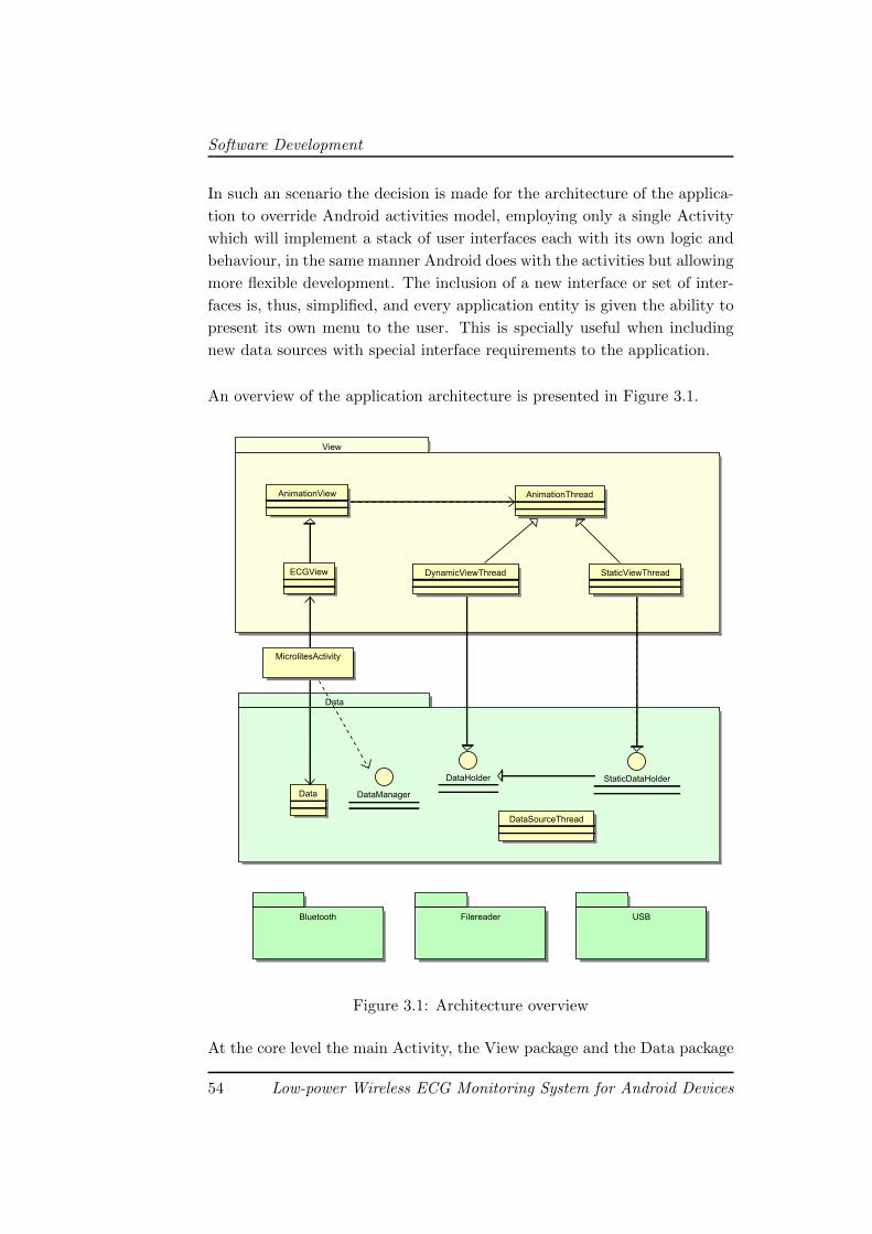
Software Development
In such an scenario the decision is made for the architecture of the applica-
tion to override Android activities model, employing only a single Activity
which will implement a stack of user interfaces each with its own logic and
behaviour, in the same manner Android does with the activities but allowing
more flexible development. The inclusion of a new interface or set of inter-
faces is, thus, simplified, and every application entity is given the ability to
present its own menu to the user. This is specially useful when including
new data sources with special interface requirements to the application.
An overview of the application architecture is presented in Figure 3.1.
View
Data
Bluetooth Filereader USB
DataSourceThread
StaticDataHolder
MicrolitesActivity
ECGView
AnimationView AnimationThread
DynamicViewThread StaticViewThread
Data
DataHolder
DataManager
Figure 3.1: Architecture overview
At the core level the main Activity, the View package and the Data package
54 Low-power Wireless ECG Monitoring System for Android Devices
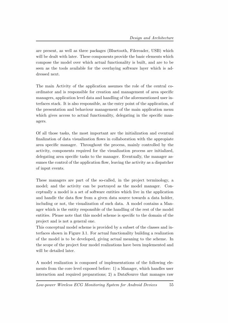
Design and Architecture
are present, as well as three packages (Bluetooth, Filereader, USB) which
will be dealt with later. These components provide the basic elements which
compose the model over which actual functionality is built, and are to be
seen as the tools available for the overlaying software layer which is ad-
dressed next.
The main Activity of the application assumes the role of the central co-
ordinator and is responsible for creation and management of area specific
managers, application level data and handling of the aforementioned user in-
terfaces stack. It is also responsible, as the entry point of the application, of
the presentation and behaviour management of the main application menu
which gives access to actual functionality, delegating in the specific man-
agers.
Of all those tasks, the most important are the initialization and eventual
finalization of data visualization flows in collaboration with the appropiate
area specific manager. Throughout the process, mainly controlled by the
activity, components required for the visualization process are initialized,
delegating area specific tasks to the manager. Eventually, the manager as-
sumes the control of the application flow, leaving the activity as a dispatcher
of input events.
These managers are part of the so-called, in the project terminology, a
model; and the activity can be portrayed as the model manager. Con-
ceptually a model is a set of software entities which live in the application
and handle the data flow from a given data source towards a data holder,
including or not, the visualization of such data. A model contains a Man-
ager which is the entity responsible of the handling of the rest of the model
entities. Please note that this model scheme is specific to the domain of the
project and is not a general one.
This conceptual model scheme is provided by a subset of the classes and in-
terfaces shown in Figure 3.1. For actual functionality building a realization
of the model is to be developed, giving actual meaning to the scheme. In
the scope of the project four model realizations have been implemented and
will be detailed later.
A model realization is composed of implementations of the following ele-
ments from the core level exposed before: 1) a Manager, which handles user
interaction and required preparations; 2) a DataSource that manages raw
Low-power Wireless ECG Monitoring System for Android Devices 55
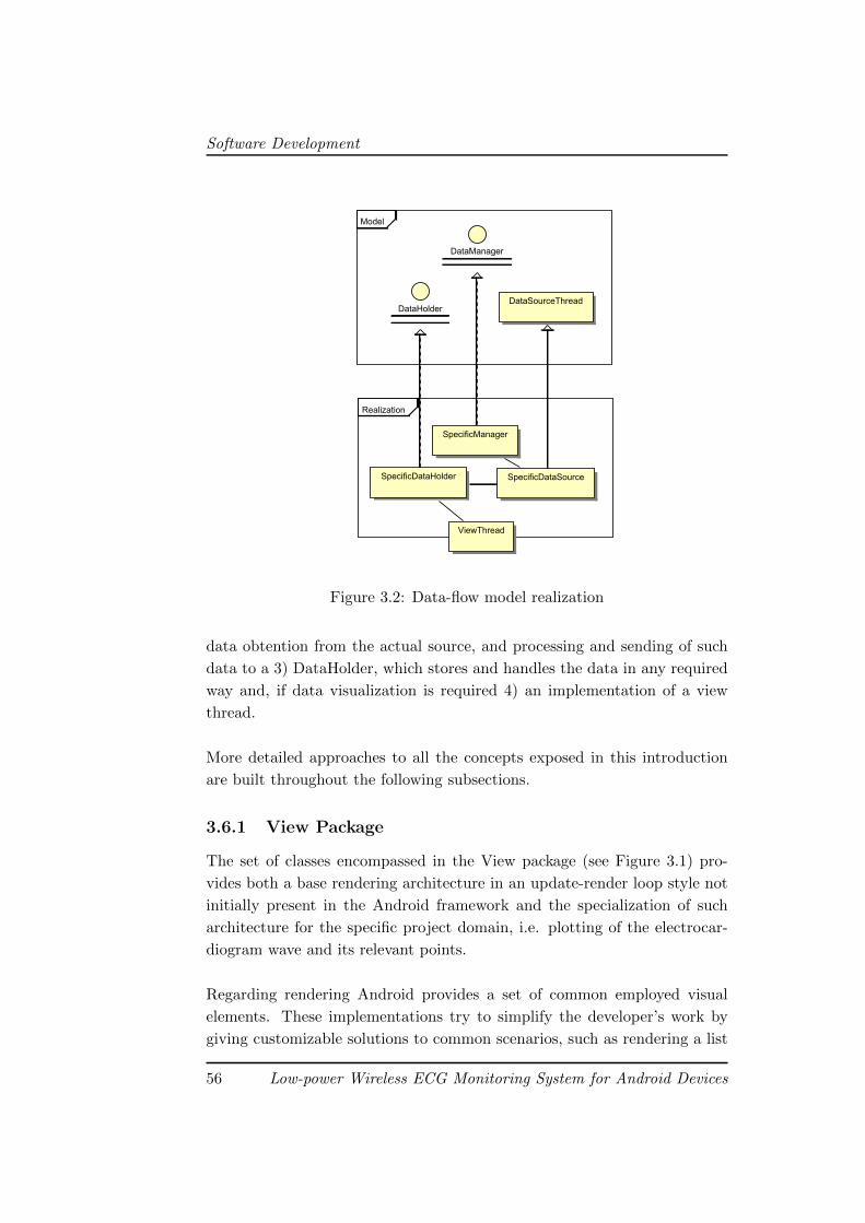
Software Development
Model
Realization
DataManager
ViewThread
DataSourceThreadDataHolder
SpecificManager
SpecificDataSourceSpecificDataHolder
Figure 3.2: Data-flow model realization
data obtention from the actual source, and processing and sending of such
data to a 3) DataHolder, which stores and handles the data in any required
way and, if data visualization is required 4) an implementation of a view
thread.
More detailed approaches to all the concepts exposed in this introduction
are built throughout the following subsections.
3.6.1 View Package
The set of classes encompassed in the View package (see Figure 3.1) pro-
vides both a base rendering architecture in an update-render loop style not
initially present in the Android framework and the specialization of such
architecture for the specific project domain, i.e. plotting of the electrocar-
diogram wave and its relevant points.
Regarding rendering Android provides a set of common employed visual
elements. These implementations try to simplify the developer’s work by
giving customizable solutions to common scenarios, such as rendering a list
56 Low-power Wireless ECG Monitoring System for Android Devices
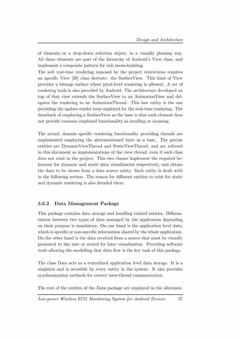
Design and Architecture
of elements or a drop-down selection object, in a visually pleasing way.
All these elements are part of the hierarchy of Android’s View class, and
implement a composite pattern for rich menu-building.
The soft real-time rendering imposed by the project restrictions requires
an specific View [29] class derivate: the SurfaceView. This kind of View
provides a bitmap surface where pixel-level rendering is allowed. A set of
rendering tools is also provided by Android. The architecture developed on
top of that view extends the SurfaceView to an AnimationView and del-
egates the rendering to an AnimationThread. This last entity is the one
providing the update-render loop employed for the real-time rendering. The
drawback of employing a SurfaceView as the base is that such element does
not provide common employed functionality as scrolling or zooming.
The actual, domain specific rendering functionality providing threads are
implemented employing the aforementioned layer as a base. The precise
entities are DynamicViewThread and StaticViewThread, and are referred
in this document as implementations of the view thread, even if such class
does not exist in the project. This two classes implement the required be-
haviour for dynamic and static data visualization respectively, and obtain
the data to be shown from a data source entity. Such entity is dealt with
in the following section. The reason for different entities to exist for static
and dynamic rendering is also detailed there.
3.6.2 Data Management Package
This package contains data storage and handling related entities. Differen-
tiation between two types of data managed by the application depending
on their purpose is mandatory. On one hand is the application level data,
which is specific or non-specific information shared by the whole application.
On the other hand is the data received from a source that must be visually
presented to the user or stored for later visualization. Providing software
tools allowing the modelling that data flow is the key task of this package.
The class Data acts as a centralized application level data storage. It is a
singleton and is accesible by every entity in the system. It also provides
synchronization methods for correct inter-thread communication.
The rest of the entities of the Data package are employed in the aforemen-
Low-power Wireless ECG Monitoring System for Android Devices 57
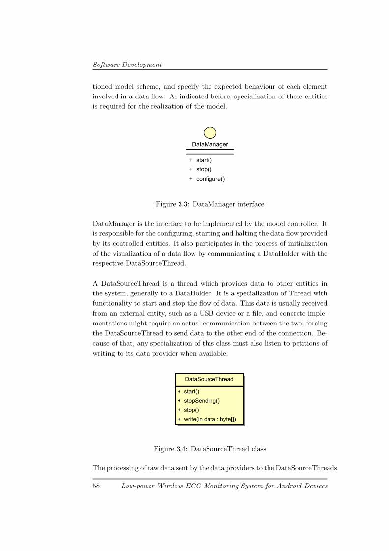
Software Development
tioned model scheme, and specify the expected behaviour of each element
involved in a data flow. As indicated before, specialization of these entities
is required for the realization of the model.
DataManager
+ start()
+ stop()
+ configure()
Figure 3.3: DataManager interface
DataManager is the interface to be implemented by the model controller. It
is responsible for the configuring, starting and halting the data flow provided
by its controlled entities. It also participates in the process of initialization
of the visualization of a data flow by communicating a DataHolder with the
respective DataSourceThread.
A DataSourceThread is a thread which provides data to other entities in
the system, generally to a DataHolder. It is a specialization of Thread with
functionality to start and stop the flow of data. This data is usually received
from an external entity, such as a USB device or a file, and concrete imple-
mentations might require an actual communication between the two, forcing
the DataSourceThread to send data to the other end of the connection. Be-
cause of that, any specialization of this class must also listen to petitions of
writing to its data provider when available.
DataSourceThread
+ start()
+ stopSending()
+ stop()
+ write(in data : byte[])
Figure 3.4: DataSourceThread class
The processing of raw data sent by the data providers to the DataSourceThreads
58 Low-power Wireless ECG Monitoring System for Android Devices
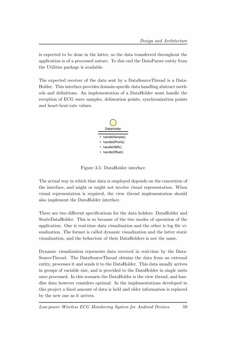
Design and Architecture
is expected to be done in the latter, so the data transferred throughout the
application is of a processed nature. To this end the DataParser entity from
the Utilities package is available.
The expected receiver of the data sent by a DataSourceThread is a Data-
Holder. This interface provides domain-specific data handling abstract meth-
ods and definitions. An implementation of a DataHolder must handle the
reception of ECG wave samples, delineation points, synchronization points
and heart-beat-rate values.
DataHolder
+ handleSample()
+ handleDPoint()
+ handleHBR()
+ handleOffset()
Figure 3.5: DataHolder interface
The actual way in which that data is employed depends on the concretion of
the interface, and might or might not involve visual representation. When
visual representation is required, the view thread implementation should
also implement the DataHolder interface.
There are two different specifications for the data holders: DataHolder and
StaticDataHolder. This is so because of the two modes of operation of the
application. One is real-time data visualization and the other is log file vi-
sualization. The former is called dynamic visualization and the latter static
visualization, and the behaviour of their DataHolders is not the same.
Dynamic visualization represents data received in real-time by the Data-
SourceThread. The DataSourceThread obtains the data from an external
entity, processes it and sends it to the DataHolder. This data usually arrives
in groups of variable size, and is provided to the DataHolder in single units
once processed. In this scenario the DataHolder is the view thread, and han-
dles data however considers optimal. In the implementations developed in
this project a fixed amount of data is held and older information is replaced
by the new one as it arrives.
Low-power Wireless ECG Monitoring System for Android Devices 59
Software Development
Static visualization, on the other hand, involves reading a file, usually mega-
byte sized. The reception of big quantities of data in single units by the data
holder, as would occur if the original DataSource specification was employed,
could lead to severe slow-downs and application performance would be af-
fected. To avoid such issues, the StaticDataHolder specification is developed.
A StaticDataHolder does not actually hold the data: it delegates that task
to its DataSourceThread. The data source will provide the StaticData-
Holder with a reference to the actual data. This way big amounts of data
transferring is avoided. The inheritance relation between DataHolder and
StaticDataHolder is imposed by the architecture, which requires a Data-
Holder to be passed to a DataSourceThread.
3.6.3 Utilities Package
This package contains reusable components providing very specific func-
tionality so they are considered utilities: RealTimeDataParser, StaticData-
Parser and Viewport.
A data parser is the entity responsible of the processing of the raw data ob-
tained by a DataSource into the domain specific data that the application
manages. There are two implementations, one for real-time data reception,
RealTimeDataParser, and the other for static data reading, i.e. a log file.
The real-time data parser is also responsible of storing the received raw data
to a log file.
A data parser is intended to be contained in a DataSourceThread. It re-
ceives the bytes of raw data and, upon successful identification of a valid data
element, notifies the corresponding DataHolder entity of the arrival. In a
theoric, performance-independant model, this behaviour would be incorrect:
the data parser would leave the processed data in the DataSourceThread,
which would then make the transfer of information to the data holder. This
kind of implementation is not valid with the soft real-time requirements of
the project, as the data source - data parser - data source - data holder flow
would be a severe bottle-neck.
The Viewport entity is a container for the visualization area settings. It
60 Low-power Wireless ECG Monitoring System for Android Devices
Design and Architecture
represents the window in which the data plotting is done, and holds in-
formation about size and position of it. It also contains data about the
horizontal and vertical scale of the rendering and handles modification of all
these parameters. It is employed by the view thread hierarchy.
3.6.4 Data Flow Model Realizations
Having explained the data flow model scheme and the core level architectural
elements employed in its construction, model realizations implemented are
detailed next. For each realization, the concretion of each model element
will be exposed including particular details of such implementation.
Bluetooth Model
The Bluetooth model is a real-time visualization targeted data flow where
the actual data provider is a Bluetooth node. As visualization is an ob-
jective, this model realization employs a DataManager, a DataSource, a
DataHolder and a DynamicViewThread; the latter two being implemented
in the same entity. An overview of the realization is shown in Figure 3.6.
The specialization of the DataManager is the BluetoothManager. It prompts
the user for the device to connect to and handles connection by employing
two threads: ConnectThread and ConnectedThread. After discovering the
available nodes, it locates the node indicated by the user and launches the
ConnectionThread.
This ConnectThread is the thread which actually manages the connection
by obtaining its endpoints in the form of a socket. If successful, passes the
socket to the manager and finishes its execution. The manager then launches
the ConnectedThread, which receives the socket and data flow starts. The
reason for employing a thread for establishing the connection is to avoid
blocking the application while connecting.
ConnectedThread is the DataSourceThread implementation and contains an
entity of DataParser. It receives data sent by the Bluetooth device through
the socket, parses it and notifies the DataHolder implementation, which
is the DynamicViewThread. The DataParser in DataSourceThread is a
RealTimeDataParser and stores the data in a log file while processing.
Low-power Wireless ECG Monitoring System for Android Devices 61
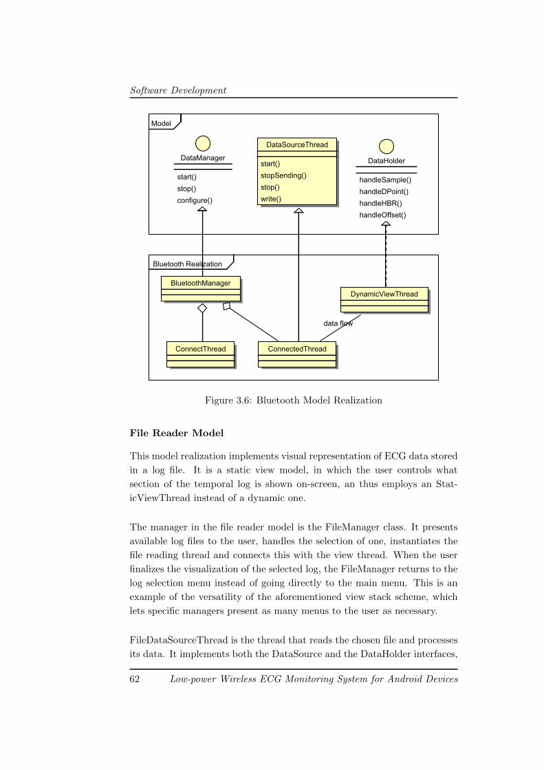
Software Development
BluetoothwRealization
Model
ConnectThread
DataHolder
handleSample()
handleDPoint()
handleHBR()
handleOffset()
ConnectedThread
DataSourceThread
start()
stopSending()
stop()
write()
BluetoothManager
DataManager
start()
stop()
configure()
DynamicViewThread
datawflow
Figure 3.6: Bluetooth Model Realization
File Reader Model
This model realization implements visual representation of ECG data stored
in a log file. It is a static view model, in which the user controls what
section of the temporal log is shown on-screen, an thus employs an Stat-
icViewThread instead of a dynamic one.
The manager in the file reader model is the FileManager class. It presents
available log files to the user, handles the selection of one, instantiates the
file reading thread and connects this with the view thread. When the user
finalizes the visualization of the selected log, the FileManager returns to the
log selection menu instead of going directly to the main menu. This is an
example of the versatility of the aforementioned view stack scheme, which
lets specific managers present as many menus to the user as necessary.
FileDataSourceThread is the thread that reads the chosen file and processes
its data. It implements both the DataSource and the DataHolder interfaces,
62 Low-power Wireless ECG Monitoring System for Android Devices
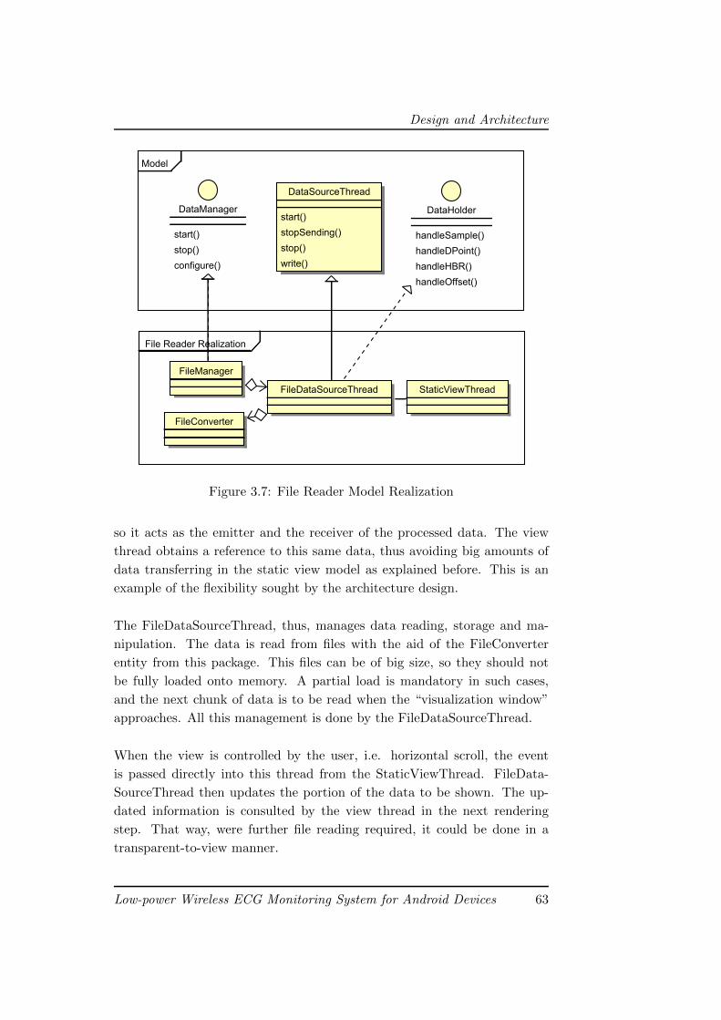
Design and Architecture
FilefReaderfRealization
Model
DataSourceThread
start()
stopSending()
stop()
write()
DataHolder
handleSample()
handleDPoint()
handleHBR()
handleOffset()
DataManager
start()
stop()
configure()
StaticViewThreadFileDataSourceThread
FileConverter
FileManager
Figure 3.7: File Reader Model Realization
so it acts as the emitter and the receiver of the processed data. The view
thread obtains a reference to this same data, thus avoiding big amounts of
data transferring in the static view model as explained before. This is an
example of the flexibility sought by the architecture design.
The FileDataSourceThread, thus, manages data reading, storage and ma-
nipulation. The data is read from files with the aid of the FileConverter
entity from this package. This files can be of big size, so they should not
be fully loaded onto memory. A partial load is mandatory in such cases,
and the next chunk of data is to be read when the “visualization window”
approaches. All this management is done by the FileDataSourceThread.
When the view is controlled by the user, i.e. horizontal scroll, the event
is passed directly into this thread from the StaticViewThread. FileData-
SourceThread then updates the portion of the data to be shown. The up-
dated information is consulted by the view thread in the next rendering
step. That way, were further file reading required, it could be done in a
transparent-to-view manner.
Low-power Wireless ECG Monitoring System for Android Devices 63
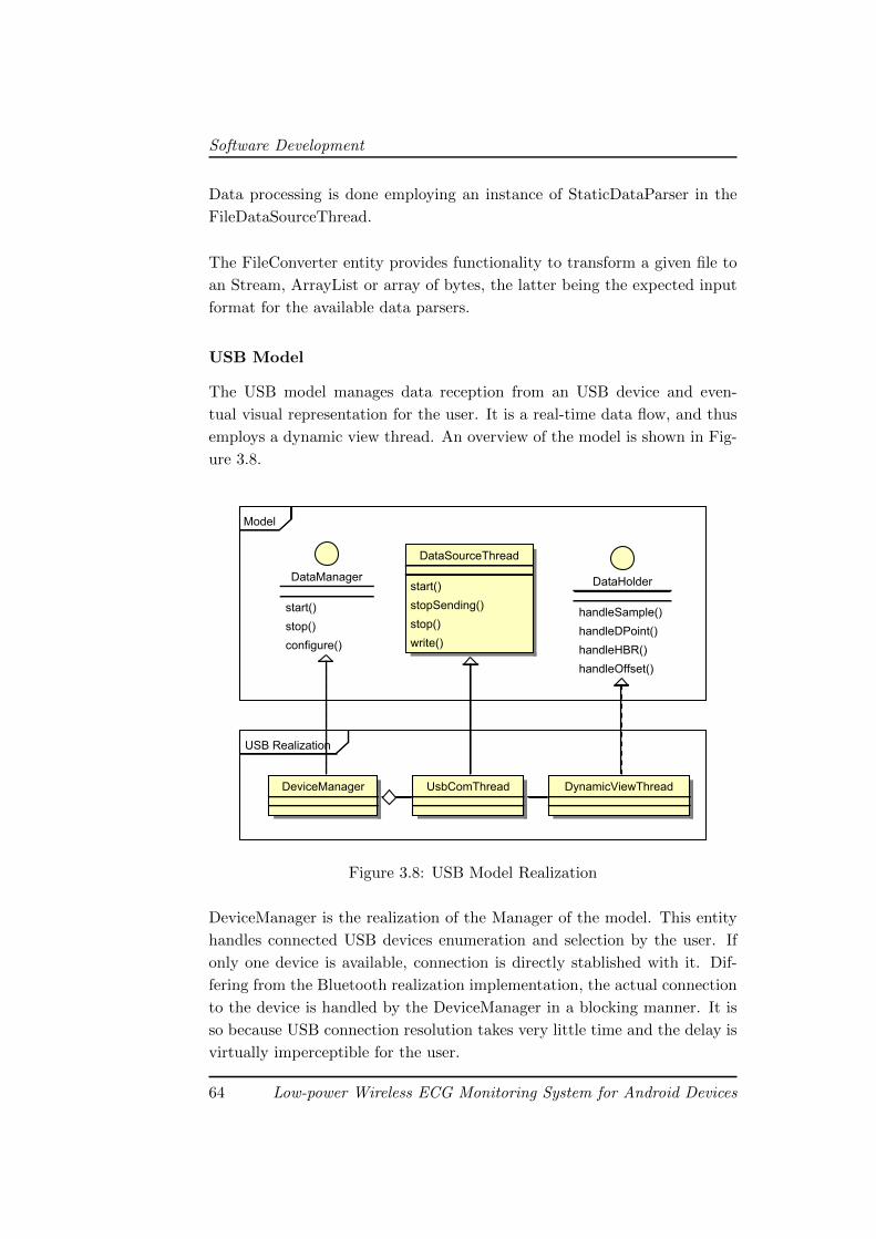
Software Development
Data processing is done employing an instance of StaticDataParser in the
FileDataSourceThread.
The FileConverter entity provides functionality to transform a given file to
an Stream, ArrayList or array of bytes, the latter being the expected input
format for the available data parsers.
USB Model
The USB model manages data reception from an USB device and even-
tual visual representation for the user. It is a real-time data flow, and thus
employs a dynamic view thread. An overview of the model is shown in Fig-
ure 3.8.
USBCRealization
Model
DataManager
start()
stop()
configure()
DataHolder
handleSample()
handleDPoint()
handleHBR()
handleOffset()
UsbComThreadDeviceManager
DataSourceThread
start()
stopSending()
stop()
write()
DynamicViewThread
Figure 3.8: USB Model Realization
DeviceManager is the realization of the Manager of the model. This entity
handles connected USB devices enumeration and selection by the user. If
only one device is available, connection is directly stablished with it. Dif-
fering from the Bluetooth realization implementation, the actual connection
to the device is handled by the DeviceManager in a blocking manner. It is
so because USB connection resolution takes very little time and the delay is
virtually imperceptible for the user.
64 Low-power Wireless ECG Monitoring System for Android Devices
Development Process
Once the connection is stablished, the DeviceManager launches an instance
of UsbComThread. This thread is the specialization of DataSourceThread
and obtains the raw data from the USB device, processes it employing an
instance of DynamicDataParser and sends the results to the view thread.
This is a DynamicViewThread entity.
3.7 Development Process
In this section a detailed description of the development is presented. The
evolution of the application architecture and functionality; design, architec-
tural and implementation decisions and explanations of the circumstances
in which they were made, as well as the development of the project schedule
are exposed in chronological order.
The section is arranged following the five iterations of the project, devel-
oping each one by presenting the target objectives and expected deadlines
for the iteration, detailing application evolution with emphasis on use case
realization and risk suppressing achievements and demonstrating the state
of the project as assessed on the reviewing meeting conducted at the end of
the iteration.
3.7.1 Project Scheduling
Before diving into the description of the development process an overview
of the project schedule is mandatory.
As it was mentioned in the previous sections, an agile software development
methodology has been applied to the project, even if artifacts from more
ordered and structured methodologies have been employed to avoid losing
focus on the critical aspects of the development.
Software development project being dependent on parallel-conducted hard-
ware research, project assets, both personal and development resources, be-
ing shared with the hardware research having the former higher priority, and
the team’s lack of formation regarding Android development are some of the
factors which lead to the adoption of such a mixed methodology. As they
have been already exposed in previous sections, they will not be detailed
here.
Low-power Wireless ECG Monitoring System for Android Devices 65
Software Development
In such an scenario, a fully developed, eight month covering schedule is un-
feasible, at least with the imposed time restrictions which does not allow
much time to be spent on planning. The decision is then made to plan only
the earlier project iterations, assuring critical functionality identified from
use case development to be implemented as soon as possible as well as higher
threat involving risk suppression to be realized.
Actual software project development begins October 15, 2011, being the fi-
nal deadline set on June 15, 2012. That deadline can not be pushed any
further, so an estimated deadline is set on May 31, 2012, leaving half a month
for further work or recovering from delays, and seven and a half months of
development time.
Time is needed for the hardware research to start providing results, and no
work can be done in the meantime on related application parts. Consid-
ering also that even in the most optimistic scenarios no actual work with
the 802.15.4 USB receiver could be done until mid February, the schedule
has to assume that the first four months of software development will need
to cover the implementation of most of the features, leaving the rest of the
development time for implementing hardware-related requirements, which
could not actually be scheduled until hardware research was evaluated.
The adopted schedule deals with the aforementioned facts by proposing five
iterations, from October 15 to May 30, complying with the fifteen days re-
served for contingencies. The first three iterations have a duration of two
months, the third one, of a single month, and the remaining one is fifteen
days long.
Having the previously developed iOS application as starting point, and be-
ing achieved at least the same feature list of that a critical target of the
project, the first two iterations are planned so as to realize UC1 and UC3
which capture requisites expressing such feature list.
The next iterations are just scrapped as no accurate estimation can be done
on the state of the project by those dates. Thus, the third iteration is
planned to cover the implementation of the remaining features, namely,
communication with the 802.15.4 receiver device, the fourth one reserved
for polishing the application and the fifth one left for testing and validation.
66 Low-power Wireless ECG Monitoring System for Android Devices
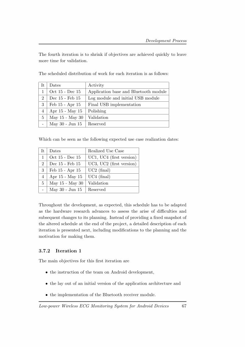
Development Process
The fourth iteration is to shrink if objectives are achieved quickly to leave
more time for validation.
The scheduled distribution of work for each iteration is as follows:
It Dates Activity
1 Oct 15 - Dec 15 Application base and Bluetooth module
2 Dec 15 - Feb 15 Log module and initial USB module
3 Feb 15 - Apr 15 Final USB implementation
4 Apr 15 - May 15 Polishing
5 May 15 - May 30 Validation
- May 30 - Jun 15 Reserved
Which can be seen as the following expected use case realization dates:
It Dates Realized Use Case
1 Oct 15 - Dec 15 UC1, UC4 (first version)
2 Dec 15 - Feb 15 UC3, UC2 (first version)
3 Feb 15 - Apr 15 UC2 (final)
4 Apr 15 - May 15 UC4 (final)
5 May 15 - May 30 Validation
- May 30 - Jun 15 Reserved
Throughout the development, as expected, this schedule has to be adapted
as the hardware research advances to assess the arise of difficulties and
subsequent changes to its planning. Instead of providing a fixed snapshot of
the altered schedule at the end of the project, a detailed description of each
iteration is presented next, including modifications to the planning and the
motivation for making them.
3.7.2 Iteration 1
The main objectives for this first iteration are
• the instruction of the team on Android development,
• the lay out of an initial version of the application architecture and
• the implementation of the Bluetooth receiver module.
Low-power Wireless ECG Monitoring System for Android Devices 67
Software Development
The alloted time for the iteration is of two monts, from October 15 to De-
cember 15. During this period the hardware research does not require much
resources, so in practical terms the full team is employed in the software
project.
In order to minimize risk AR1, the instruction of the team on Android devel-
opment becomes the key objective for the iteration. Development starts with
the implementation of the designed base architecture for the application, so
it serves as a powerful learning resource. The notion of that implementation
as disposable is not abandoned throughout iteration time and it is always
considered as a prototype to evolve or be substituted by a more refined ver-
sion once the team’s knowledge of Android increases.
Having the basic architectural framework developed, implementation of the
Bluetooth receiver module begins. Special care is put both on design and
implementation, as this functionality has to be ready as soon as posible, and
little time will be available for reimplementation further in the development.
Testing of both architecture and Bluetooth module is conducted during the
whole iteration, specially in the final weeks, so by the end of the iteration
Bluetooth module is validated and expected to be stable until the scheduled
architectural redesign.
As the Android formation phase takes less time than expected and hardware
research does not allow advancing into next iteration at the time iteration
objectives are achieved, an extra implementation effort is put to begin im-
plementation of UC4. Adjust View Parameters.
In the review meeting for the iteration the following conclusions are ob-
tained:
• Basic architecture implementation is done.
• Android is confirmed to be a very comfortable development environ-
ment even if non-standard functionality is not that easily achieved.
Instruction is planned to continue.
• Realization of UC1-View data from Bluetooth is finished. Related user
interface is not final, but it is functional, and is to be updated on
further iterations.
68 Low-power Wireless ECG Monitoring System for Android Devices
Development Process
• Realization of UC4-Adjust view parameters is done in relation to Blue-
tooth visualization. As remaining modules are developed, further work
is to be done in this field.
3.7.3 Iteration 2
The main objectives for the second iteration are
• the development of the USB communication module and
• the implementation of the Log visualization module.
The hardware reserarch having provided successful results regarding the
initial prototypes of the USB accessory, the scheduled USB module imple-
mentation for this iteration is mantained, but delayed until further testing
can be done in the hardware area. In that scenario this iteration begins with
the implementation of the log visualization module.
Module design and implementation are to change little in following itera-
tions to allow the scheduled architecture rewriting to be realized and trying
to minimize the possibility of risk PR1. This situation and the fact that a
lot of resources are required in the hardware area makes the achievement of
this objective fill most part of the iteration time.
Full expected functionality is implemented, including the remaining features
from UC4-Adjust view parameters, but validation testing indicates low per-
formance in log visualization caused by big memory requirements. Effort
needs to be put into the other iteration objective, so log visualization is
halted at this point, scheduling the development of required optimizations
for the next iteration.
Having the USB accessory prototype in an usable state, development of the
USB communication module begins. At this point the USB accessory could
only operate assuming the role of host in the connection, so the disposability
of the module is acknowledged. Nevertheless, this implementation is a must
if the project goals are to be achieved, as it serves as first-hand instruction
regarding USB development in Android. Moreover, if the hardware project
is unable to produce an USB slave accessory, with the developed module the
project would not have fully failed. Eventually this development has proven
being key for the first tests with the actual target hardware platform.
Low-power Wireless ECG Monitoring System for Android Devices 69
Software Development
During the implementation of the USB communication module the log writ-
ing is improved, so, except for the aforementioned performance optimiza-
tions, the log part of the application is finished.
With the basic interface, disposable architecture and fully functional data
flow modules, full application functionality is implemented by the end of the
iteration, and in the review meeting the following conclusions are obtained:
• Full functionality has been implemented in the application and the
product of this iteration is, as expected, the first prototype of the
application.
• Realization of UC2-View data from USB Receiver is done until hard-
ware research advances. Current implementation can act as the actual
version of the use case realization if hardware research is not fulfilled.
• Realization of UC3-View data from file log is done.
• Realization of UC4-Adjust view parameters is now finished. All re-
quired view controls are implemented.
• Risk PR1-Functionality of the application is inferior to that featured by
existing iOS application is marked as surpassed, as key functionality
is implemented.
• Risk MR1-Mobile device unsuitable for target functionality is identified
to require further monitorization and is unfolded into risks AR2 and
AR3.
• Risk AR2-Android providing subpar performance when handling re-
quired data is confirmed to occur and is to be solved in the next iter-
ation.
3.7.4 Iteration 3
This is the first just-drafted iteration of the original scheduling. Taking
the prototype obtained in the previous iteration, architectural redesign and
performance optimizations are mandatory. Performance optimizations are
identified to be required in two areas: data management and data rendering.
Only data management related optimizations are addressed in this iteration.
Iteration objectives are as follow:
70 Low-power Wireless ECG Monitoring System for Android Devices
Development Process
• redesign of the application architecture,
• achievement of required performance on data management, and
• scheduling of the rest of the project time.
The main lack of the basic architecture of the protoype is that it was im-
plemented to serve as a quick prototyping base for the data flow modules.
The instruction and knowledge about the platform and the way of operation
obtained in the previous iterations are applied in the new architecture design.
This design is done targeting easy inclusion of new data flow modules al-
lowing them to employ their own user interfaces, while providing core level
software entities for building those modules. This process produces the ar-
chitecture as exposed in section 3.6.
A detailed analysis is conducted on the data management related operations
in the application, identifying the ubiquitous application of the object ori-
ented model proposed by Java added to the subpar efficiency of the Garbage
Collector as the main cause of performance loss. The alteration of the pro-
gramming paradigm and the employment of as basic software entities as
possible, avoiding continuous object instantiation, e.g. substitute an object
containing the four parameters of a wave delineation point, by a more basic
structure, like the same four numbers stored independently, prove to be the
most effective methods of avoiding low performance.
Following such lines of operation, performance regarding data management
is utterly improved in spite of a less developer-friendly programming envi-
ronment. During this process the data flow modules (Bluetooth, USB and
Log Viewer) are also tweaked.
The positive results obtained both in the software and hardware areas allow
a solid review of the project schedule. The decision is made to keep the divi-
sion of the remaining project time in two iterations, leaving the last, fifteen
days period for unforeseen difficulties. Of the two iterations, the first is to
be devoted to implementation of the USB host communication as hardware
project estimates completion of a first prototype halfway the iteration; and
the second, and last, iteration is planned to be employed in final testing and
validation of the application against hardware prototype.
Low-power Wireless ECG Monitoring System for Android Devices 71
Software Development
The following conclusions are obtained from this iteration’s reviewing meet-
ing:
• The architecture of the application is finished and validated.
• User interface is yet to be final and is to be addressed at the following
iteration.
• Identified solutions for performance issues are to be applied in the
rendering area.
• Risk AR1-Lack of instruction on Android development delays workflow
is marked as surpassed as the team feels comfortable enough with
Android development.
• Risk AR3-Android rendering capabilities unable to handle required data
probability is increased to Moderate and is to be addressed in the next
iteration.
• Risk HR2-802.15.4 receiver device unfeasibe probability is reduced to
Low as hardware research is providing positive results.
3.7.5 Iteration 4
This iteration is scheduled to be the last implementation iteration, and its
objectives are:
• the implementation of USB host communication,
• the achievement of required performance in rendering and,
• the implementation of actual user interfaces.
The USB slave accessory prototype is produced on time by the hardware
project, and implementation of the actual USB communication assuming
the Android device the host role is done in very short time, leaving room for
achievement of the rest of the iteration objectives and following validation.
Employment of the identified working solutions for performance issues in the
rendering area does not provide the expected results, and further research
is required. The bottle-neck in the rendering process is identified to be the
context change required by the rendering tools provided by Android. Metic-
ulous research on Android developer resources provides no other solution
than minimizing the number of calls to the rendering methods each step.
72 Low-power Wireless ECG Monitoring System for Android Devices
Development Process
Emphasis is put to the realization of this task, but to no avail.
The problem is the big amount of data required to be drawn each rendering
step. A mechanism is developed to minimize the number of lines drawn by
joining similar valued wave points, and the performance is improved, but
not at the desired level. Nevertheless further work in this area is postponed
as the achieved performance lies in the range required by the non-functional
requirements of the project.
Implementation of the actual user interfaces to be employed in the appli-
cation is addressed next. The design of these has been done throughout
the last two iterations. The implementation process takes more time than
expected as Android user interface framework is quite specific, and requires
adequation to certain rules that have to be studied beforehand.
The remaining time of the iteration is devoted to testing and validation of
the application, which has reached a near final state. Conclusions from the
review meeting follow:
• The Android application is finished and pending validation with the
actual USB receiver device.
• The realization of UC2-View data from USB Receiver is done.
• The user interface of the application is in a final state, but were changes
required they could be easily implemented as the UI is isolated from
the data flow part.
• Performance regarding rendering is not optimal, but it is in the range
defined by the requirements.
• Until validation can begin, the full team can be employed in the hard-
ware project.
• Risk HR2-802.15.4 receiver device unfeasible is marked as surpassed as
the viability of the receiver has been proved by the hardware research.
3.7.6 Final Validation
The final effort in this software project extends over the allotted time for
both the fifth iteration and the reserved final period. It is fully devoted to
testing and validation of both the application and the receiver device. Even
Low-power Wireless ECG Monitoring System for Android Devices 73
Software Development
if the initial schedule assigned only the fifth iteration to this process, delays
on the hardware project force the elongation of the testing phase.
The objectives for this period are:
• exhaustive testing of the Android application,
• validation of the application, the receiver and the delineator node act-
ing as a whole, and
• the obtention of the final version of the system by implementing the
required amendments identified by the testing procedure.
Software related testing is conducted throughout all this final step causing
minor fixes to be done to the application. No relevant software related issues
arise during the testing or the validation phases.
Risk HR1-802.15.4 receiver device delayed occurrence is the cause of the
elongation of the validation iteration, but has no actual effect on the software
project. Even when the receiver is completed the risk tracking is continued
until validation concludes, were hardware complications to arise during the
process.
The final, review meeting conclusions are as follow:
• Risk HR1 is marked as surpassed.
• The Android application is successfully validated and, thus, com-
pleted.
3.8 Closure
The software development part of the project has been able to produce the
required Android application, with all planned functionality implemented
and including user friendly interfaces. It is a rather general purpose appli-
cation inside of the domain to which it is restricted, and at its final state
it would need some specialization in order to be actually useful. This is so
because the requirement analysis process was not developed focusing on an
immediate professional employment of the application, but a replacement
for that of the UCM and EPFL project which inspired this one.
Anyhow, during the architecture design and subsequent implementation
phases great emphasis is put for the application to provide the tools to
74 Low-power Wireless ECG Monitoring System for Android Devices
Closure
act as a framework over which more specific ECG monitoring application
development can be realized. An interesting example of this is that, at the
current state, the application implements visualization of data received from
an USB device. In this project, the USB device has been the 802.15.4 USB
receiver, but any other device capable of encoding the data in the expected
way is valid as well.
In short, the software development finished providing successful results in
form of a general purpose ECG monitoring application for Android devices
which can serve as the base for more specific developments, which was ex-
actly the target objective for the software project.
Low-power Wireless ECG Monitoring System for Android Devices 75
Software Development
76 Low-power Wireless ECG Monitoring System for Android Devices
Chapter 4
Results
4.1 Final state
The production of the fully functional, low energy requiring, low sized ECG
monitoring system employing an Android device as the user interface and
802.15.4 as the wireless data transferring protocol has been achieved. The
system provides all the required functionality: real-time ECG wave data
visualization both from 802.15.4 and Bluetooth nodes and storing of the
received data in log files for afterwards visualization of these, as well as vi-
sualization parameters configuration. The system is, then, a more energy
efficient and accessible version of the one produced by the Complutense Uni-
versity of Madrid and the Ecole Polytechnique Federale de Lausanne, which
is the primary objective of the project.
This achievement is made thanks to the successful outcome of both the
hardware research and the software development processes in which the
project has been divided. Each of them requiring the employment of spe-
cific methodologies and techniques, but being, as they were, highly depen-
dent one on the other only complicated the prediction of the outcome of
them both. Thanks to the flexible scheduling conducted for each one, which
considered the potential eventualities to arise in the other and focused in
allowing rescheduling when necessary, this uncertainty has been correctly
managed, leading to the current, successfully finalized state of the project.
Regarding the hardware research part, the main goal pursued was the pro-
duction of the 802.15.4 USB receiver device for Android systems. This
device has successfully evolved from the early stages of development where
77
Results
a prototyping board was employed to a custom developed printed circuit
board which is completely designed, validated and is being produced at the
moment of writing this document.
The dimensions of this board are 61 x 32 x 35 mm, and it requires 3.3V
for correct operation, being usable with at least 3.0V. Its USB capability
allows for it to be connected to any HID compliant system, and has been
successfully employed as an 802.15.4 receiver both in Android devices and
Windows based personal computers.
In respect of the Android application, the software development project
has produced an Android application providing all required functionality,
namely visualization of ECG data from Bluetooth and USB nodes, log saving
and reading, and view controlling capabilities, designed and implemented in
a robust, expandable manner. Moreover, the application provides a domain-
specific framework for the inclusion of new data sources (like Wi-Fi or Near
Field Connection) or different source data specifications.
The application presents simple, easy to use user interfaces and very specific
functionality, which added to the following of Android proposed application
design best-practices smooth the learning curve and allow out of the box
usage of the software part of the system. Due to the expansion capabilities
of the system, new user interfaces or dialogs can also be added with ease.
The webpage for the project is available at:
http://jrecas-ws.dacya.ucm.es/doku.php?id=projects:ecg_android
Besides this document, the webpage contains both the source code of the
Android application and the schematic files of the receiver device, as well as
further info on the project.
4.2 Potential additions and expansions
Although every initially planned objective has been fulfilled, in addition
to several of them which were added during the development, there is still
room for improvements and features which were not considered or left out of
scope, since the developed application is not considered as a specific product
itself, but a framework for further developments. These improvements can
78 Low-power Wireless ECG Monitoring System for Android Devices
Potential additions and expansions
be classified according to the period planned for their implementation:
• Short-term: the following features specifically target personal use.
Considering the user is to monitor his/her own vital signs, the next
additions are thought to be useful:
– Event Tagging
Assuming the user is feeling funny or pain, it may be quite in-
teresting for him/her to be able to annotate such an event with
later revision purposes, either by him/herself or medical staff.
Furthermore, the capability of marking down one peculiar result
about the ECG delineation can also be useful.
In this way, making use of the tactile interface the Android tablet
features, this activity can be done by simply touching the rele-
vant event or result. Next, the moment which that points refers
is logged and a comment may be added to the annotation.
– Temporal Meta-Data
In the same conditions described in the previous item, it is pos-
sible that the user had felt a particular sensation in a certain
moment, yet he/she was unable to mark it. Moreover, maybe the
annotation was done and it is required to directly jump to that
certain time.
In order to ease these tasks, time-related data is to be added so
that a precise moment of the monitoring can be directly found.
In this way, the user can input the desired date so that the appli-
cation shows what was happening at that moment. In addition,
markers from previous annotations would also appear for quickly
accessing to relevant events.
– Voice Commands
Due to the particular health condition of the user, or just because
he/she is busy, direct interaction with the monitoring Android
device is likely to be impossible. If situations like these are to
happen, letting users interact with the system through their own
voice may ease the aforementioned tasks.
Low-power Wireless ECG Monitoring System for Android Devices 79
Results
Fortunately, Android provides speech recognition support through-
out its specific API, so this feature could be added without de-
veloping the whole voice recognition framework.
– Automatic Warnings
Regarding the user’s health condition or unavailability again, au-
tomatic message sending with ECG data in case of relevant hap-
penings were detected would mean a seamless way to warn the
user, relatives or qualified staff if needed. In the same direction,
multiple alternatives would be presented such as emails with GPS
location attachments or direct automatic voice calls to comple-
ment this feature.
All these features come from a potential project proposed by an spe-
cific individual, which, being affected of a certain cardiovascular dis-
ease and considering the goals and results of this specific project, has
shown interest in further specialization of the developed system for
his particular needs. This private enterprise is yet to be started, but
the inception phase has already begun, and is seeking funding. The
team of the current project is offering consulting on the viability of
the requirements of the project, and testing has been conducted of the
already available system with the interested individual.
• Long-term: this features are mainly ideas which would grant the sys-
tem with much richer capabilities and new potential, though it would
require of a greater amount of time along with specific planning and
dedication.
On one hand, the application can be focused towards professional mul-
tipatient monitoring, which could be developed in at least two alter-
native ways:
– Since the developed 802.15.4 USB receiver is also compatible
with HID-compliant devices, particularly computers, multipa-
tient monitoring could be uploaded to a devoted server from a
variable number of wireless delineaton nodes, omitting the dis-
playing service the Android application provides. Once the data
is uploaded, the Android device could connect with the men-
80 Low-power Wireless ECG Monitoring System for Android Devices
Potential additions and expansions
tioned server and download the information right from the devel-
oped application. Then, the Android tablet would act as usual
as frontend of the monitoring process, displaying the downloaded
data.
– Taking into account the relatively big display a tablet device pro-
vides, this multipatient monitoring paradigm could be directly
implemented into the Android device by extending the applica-
tion’s functionality. Among this new functionalities there would
be switching between ECG wave visualizations of different pa-
tients, simultaneous logging and server uploading as well.
On the other hand, regarding self-monitoring, the system can be adap-
ted to be applied to specific domains which impose additional time or
resource restrictions. Specifically the director of the Embedded Sys-
tems Laboratory at the EPFL, where the delineator node employed in
this project was produced in the aforementioned collaboration with the
UCM, has shown interest in the application of the low power require-
ments of the system in a specific project the EPFL is collaborating
with: Solar Impulse [30].
This particular project tries to achieve a flight around the world em-
ploying no fuel, just the energy collected from the sun. The airplane
used in the project allows only for the pilot to be in the cockpit
throughout the flight, and, thus, he/she is required to be constantly
monitorized. Among others, ECG monitorization is required, and is,
at the time, being provided by the EPFL and UCM monitoring project
with the already exposed battery implications of the employment of
Bluetooth as the wireless technology.
Considering that the space in the cockpit is very reduced, and the
amount of wires, sensors and other instruments that are present, any
operation is to be done with special care and only when absolutely
needed. Concretely, the swapping of a battery-exhausted delineator
node for another, fully-charged one, to allow the recharging of the
first, is a complex procedure as the body sensor network wires have to
be unplugged from one node and plugged into the other. Moreover,
while this procedure is being performed ECG monitorization is inter-
rupted.
Low-power Wireless ECG Monitoring System for Android Devices 81
Results
Reducing the battery consumption of the delineator node is then, a
must, and can be achieved by the employment of 802.15.4 as the wire-
less communication protocol. Because of that, the results obtained in
this project can be of great use to the Solar Impulse project.
4.3 Findings
At this point, with the development finished and having analyzed the project
results and further work lines, it seems relevant to point out some of the
findings drawn from the development of the project as a conclusion for this
document. They have been obtained both during the development process
and from the results of it, near the ending of the project.
At the inception phase of the project, even having already decided to employ
Android systems as the real-time data display for the system, the team had
doubts about the actual applicability of Android as a base for the develop-
ment of real-time applications like the one to be built in the project. During
the development the fact that Android may not be the fittest environment
for this kind of functionality became clear, as, even if the devices have, in
general, high computational power and graphic capabilites, the restrictions
imposed by the operating system substantially complicate the development
of reliable real-time functionality.
In a system like the one developed in this project, the application of an
specific display device would allow finer, prettier even, visualization of the
ECG data within the real-time restrictions in which it needs to operate, but
the benefits of employing Android significantly compensate for the afore-
mentioned lacks. The most important of this benefits, at least in the scope
of the project, are the simplicity of development of visually rich applications
Android provides and, more importantly, the high availability of Android
supporting devices. These have been exposed throughout this whole docu-
ment, but they seemed worthy of one last remark. The selection of Android
as the application target platform, assuming some limitations to the appli-
cation, which already can, or eventually will be able to, be overcame, has
been one of the best decisions made in the project.
Even with the simplicity of development provided by the Android develop-
ment kit, a development process, such as the one conducted for this project,
82 Low-power Wireless ECG Monitoring System for Android Devices
Findings
that spawns various subprojects with different characteristics and each de-
pendent on the overtaking of specific achievements on the other can be an
specially complicated task to overcome if braved incorrectly. Moreover, the
inherent uncertainty of the hardware research required even more care to be
put in the scheduling tasks.
Through the project development some key techniques have been applied
and have proven to be of great relevance for the successful outcome of it.
These are, as exposed before, the employment of a flexible schedule to al-
low change-prone, supposition based planning; a detailed risk management
procedure to be prepared for countering the difficulties arised from planning
modifications; and mantaining a constant focus on the current objective,
as well as its deadline and dependant tasks, thanks to a use case driven
development process. Great part of the success on the achievement of the
objectives of this project can be granted to the careful application of these
techniques.
Assessing now the utility of the performed development, the importance
of monitorization systems for specific cardiovascular diseases affected peo-
ple has become a reckoned fact through the development process. There
is great potential of development in this area, specially when considering
that these systems are bound to be used as a daily basis by people who
need them. Projects targeting this field of interest must always consider the
final user throughout the whole development as a little user oriented extra
effort, like reducing the operations needed for monitorization initialization
or simplifying the way in which the user inputs his/her commands, as small
as the improvement may seem to be, can substantially improve the quality
of life of the user. This is so because when using a system day after day,
apparently minor nuisances in the system interface can become a constant
source of frustration.
Production of a low energy requiring monitoring system contributes to this
by reducing the amount of interruptions to the monitoring process due to
battery recharging procedures (and the subsequent halt of common activity
because of these). As mentioned, thanks to the employment of the 802.15.4
wireless protocol, the life of the battery on the delineator node is improved
in two orders of magnitude, which means recharging it once a week instead
of twice a day.
Low-power Wireless ECG Monitoring System for Android Devices 83
Results
On the same line, employment of Android instead of iOS allows the monitor-
ing application, which displays, and more importantly, logs the ECG data,
to work in background in such a way that the operation is not interrupted by
common events such an incoming phone call or the need to look something
up on the Internet. Another important feature provided by Android is the
ability for the applications to continue running when the device enters low
power modes by, for example, disabling the display. Again, these may seem
like small features, but for a person who needs constant monitoring they are
of great importance as they affect his/her day to day life activity.
As if to corroborate these claims, when the project was entering the final
phases of development, before even the beginning of the validation proce-
dures, a cardiovascular disease affected person contacted the department
to which the project is bound and shown great interest in this particular
endeavour after being informed of the project goals and already achieved
results. Further interaction with this person produced the potential short-
term project explained in the previous section for the specialization of the
system for the particular needs of the specific cardiovascular disease. This
person is also in the process of testing the system in an actual employment
scenario such as him/hers, the feedback from this yet to come as the time of
the writing of this document, and is willing to colaborate in as much ways
as possible with the project, as it could be of great use for him/her.
Moreover, as exposed before, the director of the Embedded Systems Labo-
ratory of the EPFL is also interested in the results obtained in this project
for the application of them to the Solar Impulse project with the objective
of constantly monitoring the pilot of the solar airplane. This airplane is
equipped with a tablet device for various purposes, and the utilization of it
as the monitoring display, as well as the reduction of the battery consump-
tion of the delineator node as much as possible, being energy saving critical
for solar flight, make this scenario a great one for the employment of the
project results.
Needless to say, these signs of interest in the project make this endeavour
a personal success regardless of its actual outcome. The fact that the work
carried out throughout the last months is being confirmed to be able to
provide actual benefits to some people, which was, at heart, the ultimate
goal for the project, renders all hardship involved in the process as mere
anecdotic when compared to the personal pride it has, at the end, provided.
84 Low-power Wireless ECG Monitoring System for Android Devices

Appendices
85

Appendix A
Budget Analysis
Throughout this appendix the project budget analysis is conducted, by de-
tailed specification of both time and resource cost.
The project division in atomic tasks and the scheduling of these is exposed
in the first section, in order to justify the cost in engineer hours. The tasks
have been given sufficiently explicit names, and have been divided regard-
ing the development iteration they belong to. The Gantt chart ilustrating
the project schedule is presented next. Both the hardware and the software
subprojects are presented together in it in order to achieve a finer under-
standing of the project progression.
Once the project scheduling has been exposed, the next section presents the
asset cost analysis for the project.
87
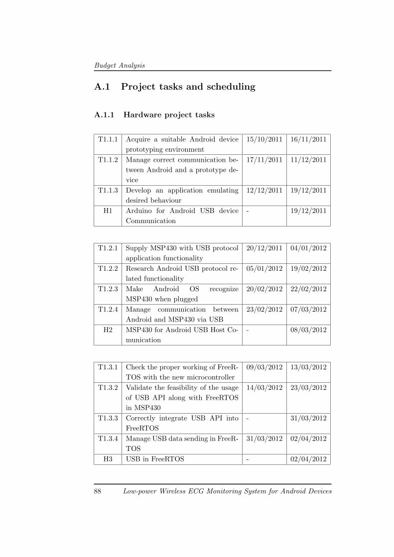
Budget Analysis
A.1 Project tasks and scheduling
A.1.1 Hardware project tasks
T1.1.1 Acquire a suitable Android device
prototyping environment
15/10/2011 16/11/2011
T1.1.2 Manage correct communication be-
tween Android and a prototype de-
vice
17/11/2011 11/12/2011
T1.1.3 Develop an application emulating
desired behaviour
12/12/2011 19/12/2011
H1 Arduino for Android USB device
Communication
- 19/12/2011
T1.2.1 Supply MSP430 with USB protocol
application functionality
20/12/2011 04/01/2012
T1.2.2 Research Android USB protocol re-
lated functionality
05/01/2012 19/02/2012
T1.2.3 Make Android OS recognize
MSP430 when plugged
20/02/2012 22/02/2012
T1.2.4 Manage communication between
Android and MSP430 via USB
23/02/2012 07/03/2012
H2 MSP430 for Android USB Host Co-
munication
- 08/03/2012
T1.3.1 Check the proper working of FreeR-
TOS with the new microcontroller
09/03/2012 13/03/2012
T1.3.2 Validate the feasibility of the usage
of USB API along with FreeRTOS
in MSP430
14/03/2012 23/03/2012
T1.3.3 Correctly integrate USB API into
FreeRTOS
- 31/03/2012
T1.3.4 Manage USB data sending in FreeR-
TOS
31/03/2012 02/04/2012
H3 USB in FreeRTOS - 02/04/2012
88 Low-power Wireless ECG Monitoring System for Android Devices
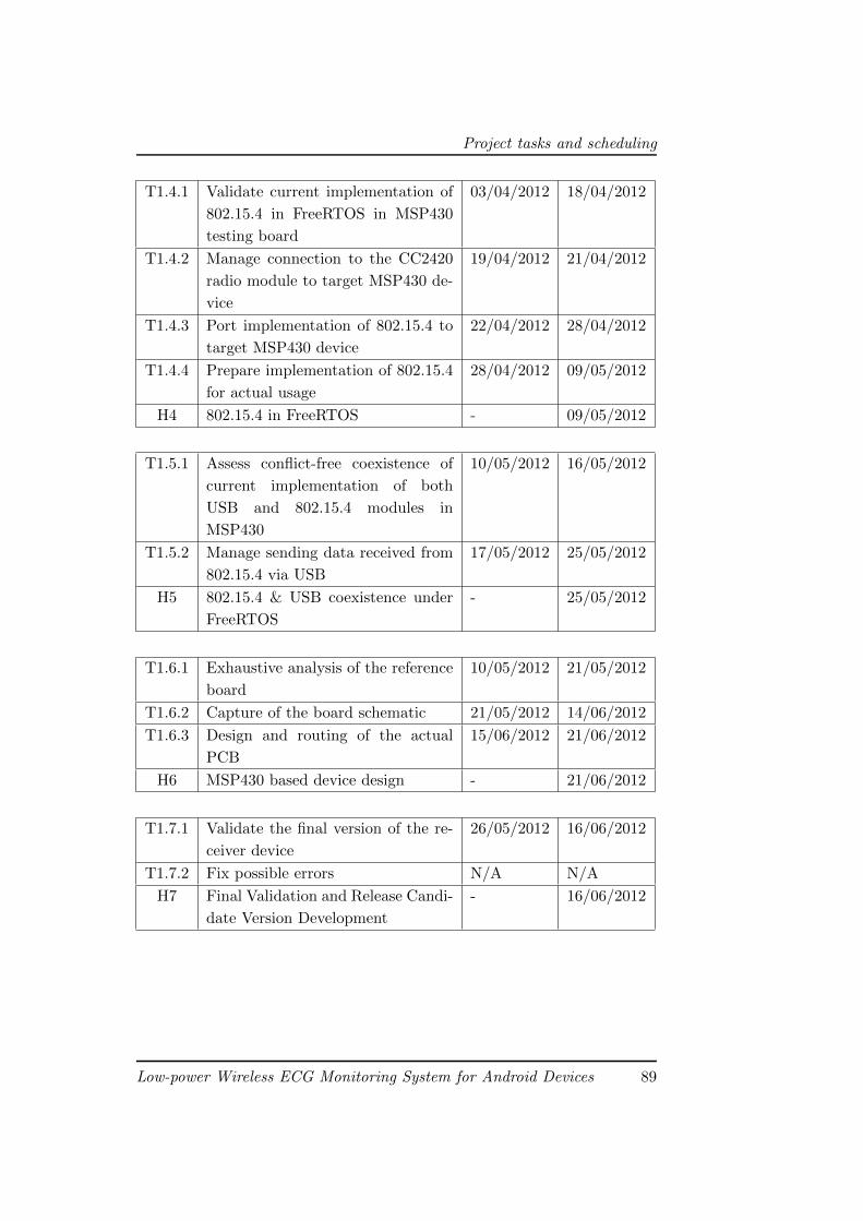
Project tasks and scheduling
T1.4.1 Validate current implementation of
802.15.4 in FreeRTOS in MSP430
testing board
03/04/2012 18/04/2012
T1.4.2 Manage connection to the CC2420
radio module to target MSP430 de-
vice
19/04/2012 21/04/2012
T1.4.3 Port implementation of 802.15.4 to
target MSP430 device
22/04/2012 28/04/2012
T1.4.4 Prepare implementation of 802.15.4
for actual usage
28/04/2012 09/05/2012
H4 802.15.4 in FreeRTOS - 09/05/2012
T1.5.1 Assess conflict-free coexistence of
current implementation of both
USB and 802.15.4 modules in
MSP430
10/05/2012 16/05/2012
T1.5.2 Manage sending data received from
802.15.4 via USB
17/05/2012 25/05/2012
H5 802.15.4 & USB coexistence under
FreeRTOS
- 25/05/2012
T1.6.1 Exhaustive analysis of the reference
board
10/05/2012 21/05/2012
T1.6.2 Capture of the board schematic 21/05/2012 14/06/2012
T1.6.3 Design and routing of the actual
PCB
15/06/2012 21/06/2012
H6 MSP430 based device design - 21/06/2012
T1.7.1 Validate the final version of the re-
ceiver device
26/05/2012 16/06/2012
T1.7.2 Fix possible errors N/A N/A
H7 Final Validation and Release Candi-
date Version Development
- 16/06/2012
Low-power Wireless ECG Monitoring System for Android Devices 89
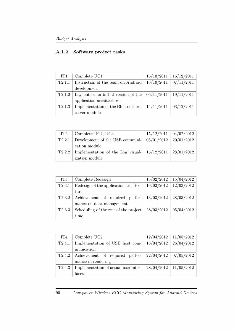
Budget Analysis
A.1.2 Software project tasks
IT1 Complete UC1 15/10/2011 15/12/2011
T2.1.1 Instruction of the team on Android
development
16/10/2011 07/11/2011
T2.1.2 Lay out of an initial version of the
application architecture
06/11/2011 19/11/2011
T2.1.3 Implementation of the Bluetooth re-
ceiver module
14/11/2011 03/12/2011
IT2 Complete UC4, UC3 15/12/2011 04/02/2012
T2.2.1 Development of the USB communi-
cation module
05/01/2012 20/01/2012
T2.2.2 Implementation of the Log visual-
ization module
15/12/2011 28/01/2012
IT3 Complete Redesign 15/02/2012 15/04/2012
T2.3.1 Redesign of the application architec-
ture
16/02/2012 12/03/2012
T2.3.2 Achievement of required perfor-
mance on data management
13/03/2012 28/03/2012
T2.3.3 Scheduling of the rest of the project
time
28/03/2012 05/04/2012
IT4 Complete UC2 12/04/2012 11/05/2012
T2.4.1 Implementation of USB host com-
munication
16/04/2012 26/04/2012
T2.4.2 Achievement of required perfor-
mance in rendering
22/04/2012 07/05/2012
T2.4.3 Implementation of actual user inter-
faces
28/04/2012 11/05/2012
90 Low-power Wireless ECG Monitoring System for Android Devices
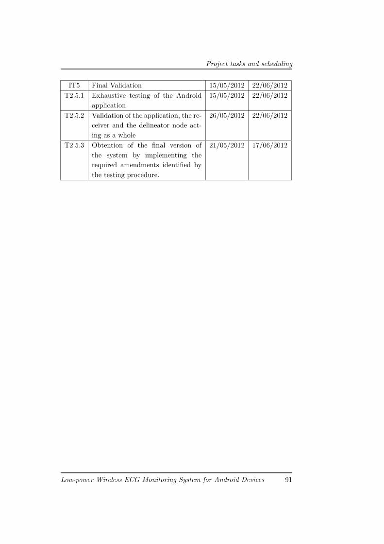
Project tasks and scheduling
IT5 Final Validation 15/05/2012 22/06/2012
T2.5.1 Exhaustive testing of the Android
application
15/05/2012 22/06/2012
T2.5.2 Validation of the application, the re-
ceiver and the delineator node act-
ing as a whole
26/05/2012 22/06/2012
T2.5.3 Obtention of the final version of
the system by implementing the
required amendments identified by
the testing procedure.
21/05/2012 17/06/2012
Low-power Wireless ECG Monitoring System for Android Devices 91
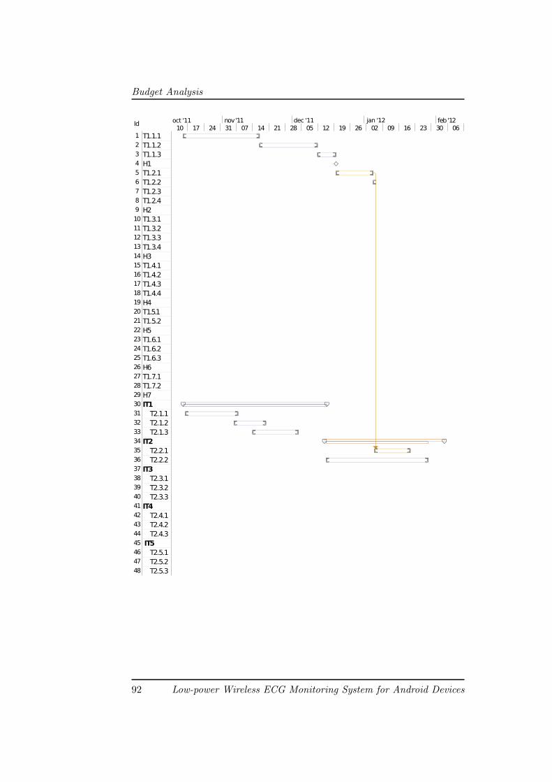
Budget Analysis
Id
1 T1.1.12 T1.1.23 T1.1.34 H15 T1.2.16 T1.2.27 T1.2.38 T1.2.49 H210 T1.3.111 T1.3.212 T1.3.313 T1.3.414 H315 T1.4.116 T1.4.217 T1.4.318 T1.4.419 H420 T1.5.121 T1.5.222 H523 T1.6.124 T1.6.225 T1.6.326 H627 T1.7.128 T1.7.229 H730 IT131 T2.1.132 T2.1.233 T2.1.334 IT235 T2.2.136 T2.2.237 IT338 T2.3.139 T2.3.240 T2.3.341 IT442 T2.4.143 T2.4.244 T2.4.345 IT546 T2.5.147 T2.5.248 T2.5.3
10 17 24 31 07 14 21 28 05 12 19 26 02 09 16 23 30 06nov '11 dec '11 feb '12jan '12oct '11
92 Low-power Wireless ECG Monitoring System for Android Devices
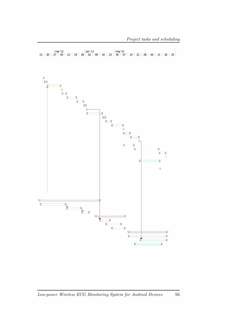
Project tasks and scheduling
13 20 27 05 12 19 26 02 09 16 23 30 07 14 21 28 04 11 18 25mar '12 apr '12 may '12
Low-power Wireless ECG Monitoring System for Android Devices 93
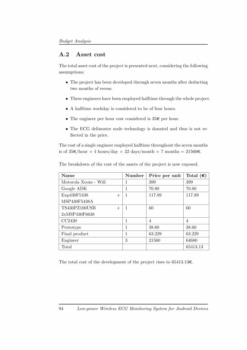
Budget Analysis
A.2 Asset cost
The total asset cost of the project is presented next, considering the following
assumptions:
• The project has been developed through seven months after deducting
two months of recess.
• Three engineers have been employed halftime through the whole project.
• A halftime workday is considered to be of four hours.
• The engineer per hour cost considered is 35€ per hour.
• The ECG delineator node technology is donated and thus is not re-
flected in the price.
The cost of a single engineer employed halftime throughout the seven months
is of 35€/hour × 4 hours/day × 22 days/month × 7 months = 21560€.
The breakdown of the cost of the assets of the project is now exposed.
Name Number Price per unit Total (€)
Motorola Xoom - Wifi 1 399 399
Google ADK 1 70.80 70.80
Exp430F5438 +
MSP430F5438A
1 117.89 117.89
TS430PZ100USB +
2xMSP430F6638
1 60 60
CC2420 1 4 4
Prototype 1 38.60 38.60
Final product 1 63.229 63.229
Engineer 3 21560 64680
Total 65413.13
The total cost of the development of the project rises to 65413.13€.
94 Low-power Wireless ECG Monitoring System for Android Devices
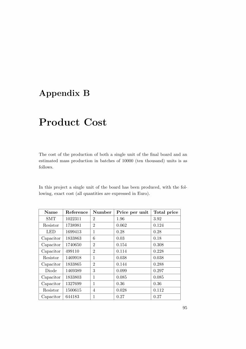
Appendix B
Product Cost
The cost of the production of both a single unit of the final board and an
estimated mass production in batches of 10000 (ten thousand) units is as
follows.
In this project a single unit of the board has been produced, with the fol-
lowing, exact cost (all quantities are expressed in Euro).
Name Reference Number Price per unit Total price
SMT 1022311 2 1.96 3.92
Resistor 1738981 2 0.062 0.124
LED 1699413 1 0.28 0.28
Capacitor 1833863 6 0.03 0.18
Capacitor 1740650 2 0.154 0.308
Capacitor 499110 2 0.114 0.228
Resistor 1469918 1 0.038 0.038
Capacitor 1833865 2 0.144 0.288
Diode 1469389 3 0.099 0.297
Capacitor 1833803 1 0.085 0.085
Capacitor 1327699 1 0.36 0.36
Resistor 1500615 4 0.028 0.112
Capacitor 644183 1 0.27 0.27
95
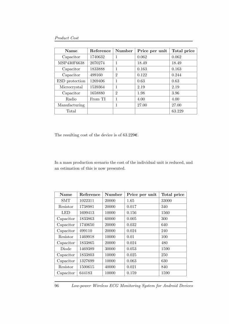
Product Cost
Name Reference Number Price per unit Total price
Capacitor 1740632 1 0.062 0.062
MSP430F6638 2070274 1 18.49 18.49
Capacitor 1833888 1 0.163 0.163
Capacitor 499160 2 0.122 0.244
ESD protection 1269406 1 0.63 0.63
Microcrystal 1539364 1 2.19 2.19
Capacitor 1658880 2 1.98 3.96
Radio From TI 1 4.00 4.00
Manufacturing 1 27.00 27.00
Total 63.229
The resulting cost of the device is of 63.229€.
In a mass production scenario the cost of the individual unit is reduced, and
an estimation of this is now presented.
Name Reference Number Price per unit Total price
SMT 1022311 20000 1.65 33000
Resistor 1738981 20000 0.017 340
LED 1699413 10000 0.156 1560
Capacitor 1833863 60000 0.005 300
Capacitor 1740650 20000 0.032 640
Capacitor 499110 20000 0.024 240
Resistor 1469918 10000 0.01 100
Capacitor 1833865 20000 0.024 480
Diode 1469389 30000 0.053 1590
Capacitor 1833803 10000 0.025 250
Capacitor 1327699 10000 0.063 630
Resistor 1500615 40000 0.021 840
Capacitor 644183 10000 0.159 1590
96 Low-power Wireless ECG Monitoring System for Android Devices
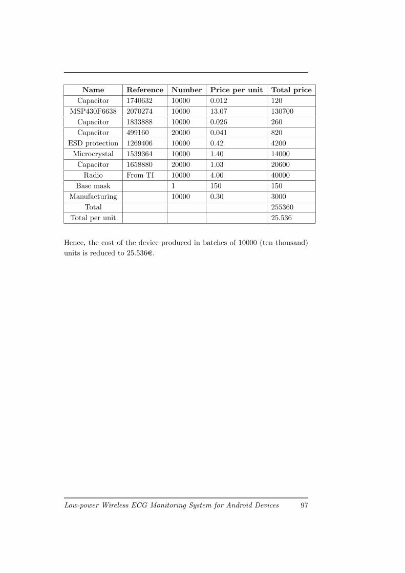
Name Reference Number Price per unit Total price
Capacitor 1740632 10000 0.012 120
MSP430F6638 2070274 10000 13.07 130700
Capacitor 1833888 10000 0.026 260
Capacitor 499160 20000 0.041 820
ESD protection 1269406 10000 0.42 4200
Microcrystal 1539364 10000 1.40 14000
Capacitor 1658880 20000 1.03 20600
Radio From TI 10000 4.00 40000
Base mask 1 150 150
Manufacturing 10000 0.30 3000
Total 255360
Total per unit 25.536
Hence, the cost of the device produced in batches of 10000 (ten thousand)
units is reduced to 25.536€.
Low-power Wireless ECG Monitoring System for Android Devices 97
Product Cost
98 Low-power Wireless ECG Monitoring System for Android Devices
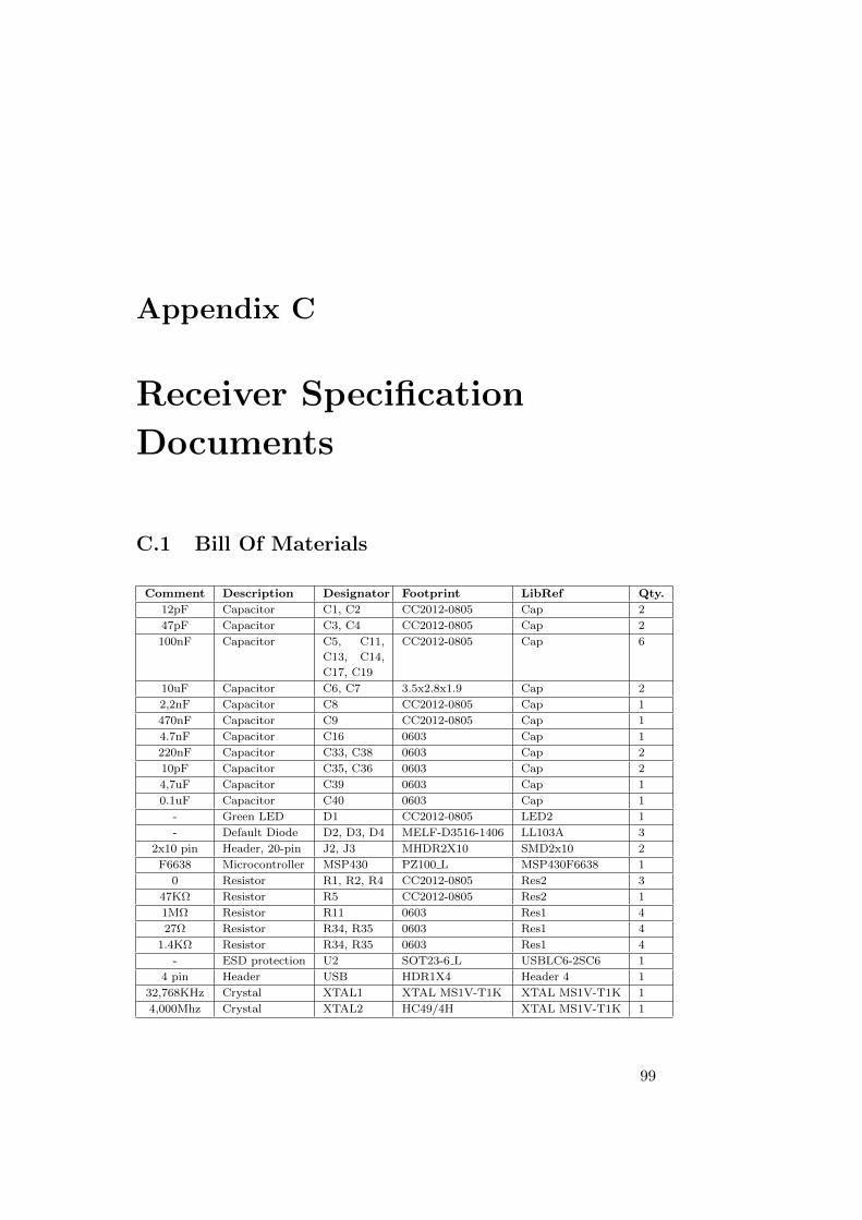
Appendix C
Receiver Specification
Documents
C.1 Bill Of Materials
Comment Description Designator Footprint LibRef Qty.
12pF Capacitor C1, C2 CC2012-0805 Cap 2
47pF Capacitor C3, C4 CC2012-0805 Cap 2
100nF Capacitor C5, C11,
C13, C14,
C17, C19
CC2012-0805 Cap 6
10uF Capacitor C6, C7 3.5x2.8x1.9 Cap 2
2,2nF Capacitor C8 CC2012-0805 Cap 1
470nF Capacitor C9 CC2012-0805 Cap 1
4.7nF Capacitor C16 0603 Cap 1
220nF Capacitor C33, C38 0603 Cap 2
10pF Capacitor C35, C36 0603 Cap 2
4,7uF Capacitor C39 0603 Cap 1
0.1uF Capacitor C40 0603 Cap 1
- Green LED D1 CC2012-0805 LED2 1
- Default Diode D2, D3, D4 MELF-D3516-1406 LL103A 3
2x10 pin Header, 20-pin J2, J3 MHDR2X10 SMD2x10 2
F6638 Microcontroller MSP430 PZ100 L MSP430F6638 1
0 Resistor R1, R2, R4 CC2012-0805 Res2 3
47KΩ Resistor R5 CC2012-0805 Res2 1
1MΩ Resistor R11 0603 Res1 4
27Ω Resistor R34, R35 0603 Res1 4
1.4KΩ Resistor R34, R35 0603 Res1 4
- ESD protection U2 SOT23-6 L USBLC6-2SC6 1
4 pin Header USB HDR1X4 Header 4 1
32,768KHz Crystal XTAL1 XTAL MS1V-T1K XTAL MS1V-T1K 1
4,000Mhz Crystal XTAL2 HC49/4H XTAL MS1V-T1K 1
99
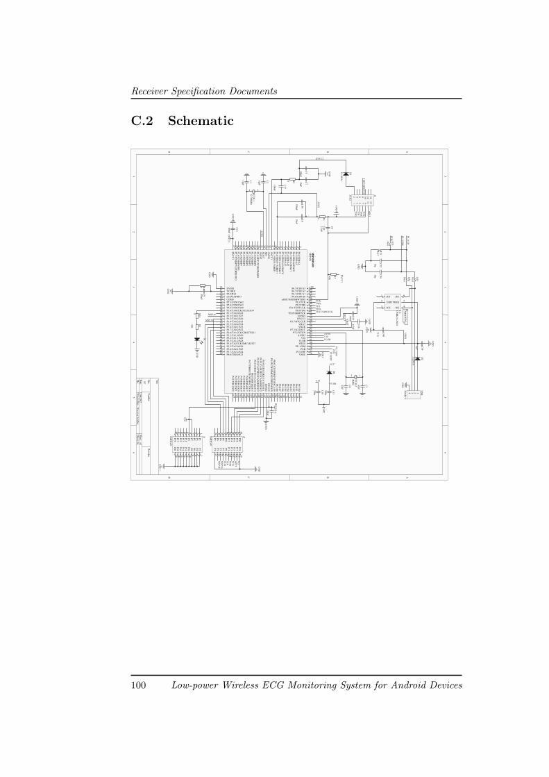
Receiver Specification Documents
C.2 Schematic
1 1
2 2
3 3
4 4
5 5
6 6
DD
CC
BB
AA
Title
Num
berR
evisionS
ize
A2
Date:
22/06/2012S
heet of
File:
Z:\E
lectrolites\..\Receiver.S
chDoc
Draw
n By:
P4
4P
66
P8
8P
1010
P12
12P
1414
P16
16P
1818
P20
20
P2
2P
11
P3
3P
55
P7
7P
99
P11
11P
1313
P15
15P
1717
P19
19J2S
MD
2x10
P4
4
P6
6
P8
8
P10
10
P12
12
P14
14
P16
16
P18
18
P20
20
P2
2P
11
P3
3
P5
5
P7
7
P9
9
P11
11
P13
13
P15
15
P17
17
P19
19
J3SM
D2x10
MS
P430F
6638
P6.4/C
B4/A
41
P6.5/C
B5/A
52
P6.6/C
B6/A
6/DA
C0
3
P6.7/C
B7/A
7/DA
C1
4
P7.4/C
B8/A
125
P7.5/C
B9/A
136
P7.6/C
B10/A
14/DA
C0
7
P7.7/C
B11/A
15/DA
C1
8
P5.0/V
RE
F+
/VeR
EF
+9
P5.1/V
RE
F-/V
eRE
F-
10
AV
CC
111
AV
SS
112
XIN
13
XO
UT
14
AV
SS
215
P5.6/A
DC
12CL
K/D
MA
E0
16
P2.0/P
2MA
P0
17
P2.1/P
2MA
P1
18
P2.2/P
2MA
P2
19
P2.3/P
2MA
P3
20
P2.4/P
2MA
P4
21
P2.5/P
2MA
P5
22
P2.6/P
2MA
P6/R
0323
P2.7/P
2MA
P7/L
CD
RE
F/R
1324
DV
CC
125
DVSS126
VCORE27
P5.2/R2328
LCDCAP/R3329
COM030
P5.3/COM1/S4231
P5.4/COM2/S4132
P5.5/COM3/S4033
P1.0/TA0CLK/ACLK/S3934
P1.1/TA0.0/S3835
P1.2/TA0.1/S3736
P1.3/TA0.2/S3637
P1.4/TA0.3/S3538
P1.5/TA0.4/S3439
P1.6/TA0.1/S3340
P1.7/TA0.2/S3241
P3.0/TA1CLK/CBOUT/S3142
P3.1/TA1.0/S3043
P3.2/TA1.1/S2944
P3.3/TA1.2/S2845
P3.4/TA2CLK/SMCLK/S2746
P3.5/TA2.0/S2647
P3.6/TA2.1/S2548
P3.7/TA2.2/S2449
P4.0/TB0.0/S2350
P4.1/T
B0.1/S
2251
P4.2/T
B0.2/S
2152
P4.3/T
B0.3/S
2053
P4.4/T
B0.4/S
1954
P4.5/T
B0.5/S
1855
P4.6/T
B0.6/S
1756
P4.7/T
B0O
UT
H/S
VM
OU
T/S
1657
P8.0/T
B0C
LK
/S15
58P
8.1/UC
B1S
TE
/UC
A1C
LK
/S14
59P
8.2/UC
A1T
XD
/UC
A1S
IMO
/S13
60P
8.3/UC
A1R
XD
/UC
A1S
OM
I/S12
61P
8.4/UC
B1C
LK
/UC
A1S
TE/S
1162
DV
SS
263
DV
CC
264
P8.5/U
CB
1SIM
O/U
CB
1SD
A/S
1065
P8.6/U
CB
1SO
MI/U
CB
1SC
L/S
966
P8.7/S
867
P9.0/S
768
P9.1/S
669
P9.2/S
570
P9.3/S
471
P9.4/S
372
P9.5/S
273
P9.6/S
174
P9.7/S
075
VSSU 76PU.0/DP 77
PUR78PU.1/DM79
VBUS 80VUSB 81
V1882AVSS383P7.2/XT2IN84
P7.3/XT2OUT 85VBAK
86VBAT87P5.7/RTCCLK88
DVCC3 89DVSS3
90TEST/SBWTCK91PJ.0/TDO92
PJ.1/TDI/TCLK 93PJ.2/TMS
94PJ.3/TCK95nRST/NMI/SBWTDIO96
P6.0/CB0/A0 97P6.1/CB1/A1
98P6.2/CB2/A299P6.3/CB3/A3100
MS
P430
MS
P430F
6638
GN
D
D1
330
R3
0 R01
GN
D
470nFC
90 R
4
100nF
C13
GN
D100nF
C11
GN
D
GN
D
1234
US
B
Header 4
DV
CC
1
12
4MH
zX
TA
L247pF
C4
47pF
C3
DV
CC
1
D2
LL
103A4u7
C39
1 2
32.768KH
zX
TA
L1
12pF
C2
12pF
C1
GN
D
GN
D
0.1u
C40
VB
US
R35
Res1
R34
Res1
10p
C36
10p
C35
GN
D
R33
Res1
R11
Res1
PU
.0/DP
PU
.0/DP
PU
.1/DM
PU
.1/DM
PU
R
PU
R
4.7nF
C16
GN
D
VB
AT
100nFC
19
GN
D
DV
CC
1
GN
D220n
C33
220n
C38
GN
D
V18
V18
VUSB
VUSB
D4
VCC
AV
SS
12
34
56
78
910
1112
1314
J4JTA
G
AVSS
TE
ST
/SB
WT
CK
TEST/SBWTCK
100nF
C17
0 R2 10uF
C7
100nF
C5 D
3
LL
103A
GN
D
DVCC1
100nF
C14
10uF
C6
AV
SS
0 R1
47K
R5
DV
CC
1
TDOTDITMSTCK
TD
OT
DI
TM
ST
CK
GN
D
GN
D
VC
C
MSP38
MSP36
MS
P38
MS
P36
GN
D
GN
D
2.2nF
C8
Cap
IO11
GND2
IO23 IO2 4
VBUS5
IO1 6
U2
US
BL
C6-2S
C6
TD
OT
DI
TM
ST
CK
nRS
T
nRS
TV
cc
Antes IO
3?
100 Low-power Wireless ECG Monitoring System for Android Devices
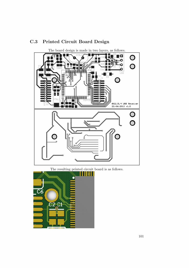
C.3 Printed Circuit Board Design
The board design is made in two layers, as follows.
The resulting printed circuit board is as follows.
101

102
Bibliography
[1] Real-Time Wavelet-Based Electrocardiogram Delineation
System with Automatic Arrhythmia Detection
Embedded Systems Laboratory, ESL
Ecole Polytechnique Federale de Lausanne, EPFL
http://esl.epfl.ch/cms/lang/en/pid/46016
[2] Google’s Android becomes the world’s leading smart phone
platform
Canalys
January 31, 2011
http://www.canalys.com/static/press_release/2011/
r2011013.pdf
[3] The all-conquering smartphone seems headed for ubiquity
Gizmag
September 5, 2011
http://www.gizmag.com/smartphone-sales/19723/
[4] What is Android
Android Developers
http://developer.android.com/guide/basics/
what-is-android.html
[5] Android SDK
Android Developers
http://developer.android.com/sdk/index.html
[6] Program Enrollment
iOS Developer Program
https://developer.apple.com/support/ios/
enrollment.html#systemrequirements
103
[7] Development and Evaluation of Multilead Wavelet-Based
ECG Delineation Algorithms for Embedded Wireless Sensor
Nodes
F. Rincon, J. Recas, N. Khaled, D. Atienza
IEEE Transactions On Information Technology In
Biomedicine, Vol. 15, No. 6, p. 854-863
November, 2011
[8] Android ZigBee Interface
Texas Instruments
http://processors.wiki.ti.com/index.php/Android_
ZigBee_Interface
[9] Cardiovascular diseases (CVDs)
World Health Organization
http://www.who.int/mediacentre/factsheets/fs317/
en/index.html
[10] Unauthorized modification of iOS as a major source of insta-
bility, disruption of services, and other issues
Apple Support
September 27, 2010
http://support.apple.com/kb/ht3743
[11] IEEE Std 802.15.4TM-2006
(Revision of IEEE Std 802.15.4-2003)
Institute of Electrical and Electronics Engineers
June 7, 2006
[12] Android Open Accessory Development Kit
Android Developers
http://developer.android.com/guide/topics/usb/adk.
html
[13] Android Open Accessory API and Development Kit (ADK)
Mike Lockwood, Erik Gilling & Jeff Brown
May 10, 2011
http://www.google.com/events/io/2011/sessions/
android-open-accessory-api-and-development-kit-adk.
html
104
[14] IEEE 802.15.4/ZigBeeTMUSB Dongle
Integration, Adaptive Modules
http://www.adaptivemodules.com/assets/File/
integration_802-15-4_usb%20dongle.pdf
[15] TI presents World’s first platform bringing ZigBee to Android
smartphones and tablets.
Texas Instruments
March 04, 2011
http://www.ti.com/ww/in/news_detail/2011/news_
detail_20110304.html
[16] mbed: Rapid Prototyping with Microcontrollers
ARM Holdings
http://mbed.org/
[17] TI MSP430. Getting started
Texas Instruments
http://www.ti.com/lsds/ti/microcontroller/16-bit_
msp430/getting_started.page
[18] MSP430 Family Instruction Set Summary
Texas Instruments
http://www.ti.com/sc/docs/products/micro/msp430/
userguid/as_5.pdf
[19] MSP430F543xA, MSP430F541xA Mixed Signal Microcon-
troller Datasheet
Texas Instruments
http://www.ti.com/lit/ds/symlink/msp430f5438a.pdf
[20] MSP430F663x Family Mixed Signal Microcontroller
Datasheet
Texas Instruments
http://www.ti.com/lit/ds/symlink/msp430f6638.pdf
[21] MSP - EXP430F5438
Texas Instruments
http://www.ti.com/tool/msp-exp430f5438
105
[22] MSP - TS430PZ100USB
Texas Instruments
http://www.ti.com/tool/msp-ts430pz100usb
[23] Shimmer Platform - Key Features
Shimmer Research
http://www.shimmer-research.com/r-d/
platform-features
[24] Shimmer Expansion Modules
Shimmer Research
http://www.shimmer-research.com/r-d/hardware/
extension-modules
[25] USB Host and Accessory
Android Developers
http://developer.android.com/guide/topics/usb/
index.html
[26] MSP430 USB Developers Package
Texas Instruments
http://www.ti.com/tool/msp430usbdevpack
[27] Motorola XOOMTM Fact Sheet
Motorola
http://mediacenter.motorola.com/Fact-Sheets/
Motorola-XOOM-Fact-Sheet-3537.aspx
[28] Activities
Android Developers
http://developer.android.com/guide/topics/
fundamentals/activities.html
[29] View
Android Developers
http://developer.android.com/reference/android/
view/View.html
[30] Solar Impulse
http://solarimpulse.com/
106