Embed Size (px)
Citation preview
DVCon 2012: 131-II287: Low Power SoC Verification: IP Reuse and Hierarchical Composition using UPF
1
Abstract—Power management is a critical feature of today’s
SoCs, almost as important as functionality. IEEE 1801™-2009
UPF enables specification of the intended power management
infrastructure for an SoC to enable early verification and to drive
implementation. Just as the complexity of an SoC demands a
well-structured hierarchical approach to design and verification
of its functional specification, the complexity of the power
management infrastructure for an SoC similarly requires a
hierarchical methodology that enables separation of concerns
and supports partitioning, parallel development, and reuse.
In this paper, we propose a hierarchical methodology for the
use of IEEE Std 1801™-2009 UPF (aka UPF 2.0) for the
specification of power intent for low power SoCs. This
methodology enables verification at the IP block level,
hierarchical composition of complex system-level power intent
specifications from IP block power intent specifications, and
automatic consistency checking to ensure that IP block
constraints are met by the system in which they are used. The
proposed methodology is illustrated in the context of a complex
SoC design architecture that was used to validate the concepts.
Index Terms — Functional Verification, Hierarchical
composition, IP Reuse, Low Power, Methodology, SoC
Integration, UPF.
I. INTRODUCTION
A. Power Aware Design
Power has become a critical aspect of electronic design.
For mobile systems, each new generation must offer new
features but at the same time must run longer on a single
battery charge. For non-mobile systems, minimizing heat and
therefore cooling costs dictates ever increasing control over
power consumption. The most recent process technologies
require aggressive power management strategies that include
not only clock gating but also power gating and use of
multiple voltages and clock frequencies. These strategies can
Amit Srivastava is a Lead Member Consulting Staff at Mentor Graphics; (e-mail: [email protected]).
Rudra Mukherjee is an Engineering Director at Mentor Graphics;
(e-mail: [email protected] ). Erich Marschner is a Product Manager at Mentor Graphics;
(e-mail: [email protected]).
Chuck Seeley is a Verification Technologist at Mentor Graphics; (e-mail: [email protected]).
Sorin Dobre is a Senior Staff Engineer at Qualcomm;
(e-mail: [email protected] ).
affect functionality if not executed correctly, which leads to an
increasing need for power aware verification.
Power aware design involves partitioning a design into
separate regions, or power domains, such that each domain
can have its power supplies managed independently. At any
given time, only a subset of the full system may be powered,
and a given portion may operate at different voltage and
consequent performance levels depending upon the operating
mode of the system. The ability to control power consumption
based on functional requirements of the system enables power
optimization for typical usage scenarios.
Power management is imposed on top of the normal
functionality of the design in a manner that is transparent to
the user. The power management infrastructure can be
thought of as a layer of logic integrated with the design logic
that controls power supplies for each separate power domain,
mediates the interfaces between power domains to ensure that
differences in power state do not interfere with functionality,
and orchestrates the transitions between power states to ensure
that system state information is preserved where required or
reinitialized as needed.
While power management logic historically has been added
to the design late in the flow, the increasing need for power
aware verification has led to methods for specifying power
intent, i.e., the intended power management infrastructure,
much earlier. A power intent specification is essentially a
virtual definition of the power management logic that will be
added in the implementation process, provided in a form that
can be implicitly integrated with an RTL description in order
to verify the RTL specification together with the planned
power management infrastructure.
B. Power Intent Specification
IEEE Standard 1801TM
-2009 Unified Power Format (UPF)
[2] enables specification of power intent. Based on Tcl, UPF
defines concepts and commands required to describe power
management requirements for IP blocks, the architecture of
the power management infrastructure for a complete system,
and even the implementation of power distribution networks.
It is used both for early verification of power intent and to
drive implementation of the power management infrastructure.
UPF defines the following concepts and terminology for
specification of power intent:
Low Power SoC Verification: IP Reuse and
Hierarchical Composition using UPF
Amit Srivastava, Rudra Mukherjee, Erich Marschner, Chuck Seeley, Mentor Graphics,
Sorin Dobre, Qualcomm
DVCon 2012: 131-II287: Low Power SoC Verification: IP Reuse and Hierarchical Composition using UPF
2
Power domain: a collection of library cells and/or
HDL module instances that typically share a common
primary supply and typically are all in the same power
state at a given time. This collection of instances is
referred to as extent of a power domain.
Power state: an abstract representation of the voltage
characteristics of a power supply, and also an abstract
representation of the operating mode of the elements of
a power domain or of a module instance (e.g., on, off,
sleep).
Isolation: logic that mediates the interaction between
logic elements that are in different power states, to
protect elements that are powered up from being
adversely affected by elements that are powered down.
Level shifting: logic that mediates the interaction
between logic elements that are powered up at different
voltage levels, to ensure that logic values generated by
one element at one voltage level are correctly
translated to the appropriate voltage level of the other
element.
Retentionlogic that enables the state of selected state
elements to be saved when a domain is powered down
and restored when the domain is powered up again.
Supply net: an abstraction of a power rail that provides
power to elements of a domain.
Supply set: an abstraction of a collection of supply
nets that, in aggregate, provide all the supply
connections required by a given logic element. The
individual nets are referred to as functions of a supply
set.
Simstate: the simulation behavior associated with a
state added on the supply set. This behavior is one of
the simstate values specified in UPF and semantics
associated with those simstate values are applied
during simulation, when the power state having that
simstate behavior is active. This behavior is applicable
to design instances which are connected to the supply
set.
Switch: a power management element that controls
whether a supply net is connected to a supply source.
Logic net: an abstraction of a control signal that
controls the operation of isolation, retention, or power
switching logic.
Driver supply: the supply set providing power to the
logic that is the ultimate source (driver) of a net.
Receiver supply: the supply set providing power to the
logic that is the ultimate sink (receiver) of a net.
A UPF specification defines the power domains, supply sets
and power states of a design and specifies strategies for
inserting isolation, level-shifting, and retention logic between
and within power domains to ensure that the design will
function correctly in all of its operating modes in the context
of the power management infrastructure.
C. The Importance of Methodology
The concepts, capabilities, and features provided by any
standard language for electronic design, whether it be Verilog,
VHDL, SystemVerilog, or UPF, are necessary but not
sufficient. The way in which those concepts, capabilities, and
features are used in practice is just as important, if not more.
In addition to the features of UPF, a well-defined
methodology for power intent specification using UPF is also
needed to ensure efficient development, interoperable tools,
and reliable results from a low power design and verification
flow.
A key consideration in the use of UPF is how to structure
the power intent specification to leverage the hierarchical
structure of the design. While it is possible to describe the
power intent for a complete system in a flat manner, all in one
file, a hierarchical approach allows for partitioning of a power
intent specification so that different portions can be
constructed at different times, or by different engineers or
teams. Hierarchical structuring also leads to reuse of
components of the power intent specification.
The IEEE 1801TM
-2009 UPF specification defines language
features that can be used to support a variety of
methodologies. However, the specification does not define
any one methodology in detail. Users have been left to work
out for themselves what methodology to adopt when using
UPF. In this paper, we propose a particular methodology that
supports hierarchical specification of power intent and reuse
of IP-level power intent specifications.
II. REQUIREMENTS
A. General Motivation
Chips today are highly complex and application specific.
Ever-increasing design complexity and shrinking process
nodes demand complex power management strategies. This
increased design effort coupled with strict time-to-market
requirements require a proper hierarchical approach, one
that supports separation of concerns, parallel development,
and reuse of previously designed, optimized and verified
design components.
There is a well-defined methodology prevalent in the design
industry which is widely used as SoC methodology. This
addresses the functional aspect of a system, but the
complexity, variety and impact of power management on the
functionality of a system demands a similar methodology for
specifying, verifying, and implementing Power Intent.
Formats for expressing power intent have been available for
some time now, but there seems to be a general lack of
methodology for the use of those formats.
The methodology for expressing power intent needs to
inherit the benefits of SoC methodology, which are –
reusability and hierarchical composition. Along with that
they need to be general enough to cater to a variety of power
management demands for different sub-components.
It is also important for the methodology for Power Intent
specification to empower tools to automate a lot of redundant
tasks, perform efficient integration and provide consistency
DVCon 2012: 131-II287: Low Power SoC Verification: IP Reuse and Hierarchical Composition using UPF
3
checks, hence reducing the chances of design bugs and
functional failures related to power management.
B. IP based development [1]
Intellectual Property (IP) is a critical component for SoC
based design methodology. In order to achieve lesser time to
market it becomes necessary to reuse an existing IP by
integrating it in their chip and hence improving the overall
productivity. An IP block is a predesigned component that can
be used in a larger design. There are two major kinds of IP.
Hard IP is a predesigned layout with all power
management functionality built into the IP itself. A large
number of memories are delivered as hard IPs. Another
example of hard IPs is analog and mixed signal components
which are directly integrated in SoCs, e.g. low-dropout
regulators (LDOs), DDR PHYs, USB PHYs, PLLs etc.
Soft IP comes as a synthesizable module in hardware
description languages (HDL) such as SystemVerilog or
VHDL. Soft IP is designed to be implemented using logic
synthesis and place-and-route tools. As such, it is more easily
targeted to a new manufacturing process, perhaps at some cost
in performance, power, and area. A surprising number of large
blocks, including CPUs, DSPs and specialized hardware
accelerators are delivered only as soft IP.
C. Verification Models for IP
In order to verify the functionality of IP blocks, vendors
provide verification models for their IPs. The verification
models allow simulation tools to simulate the IP in the SoC
environment. The verification models come in different
flavors.
Behavioral verification models describe functional
behavior in a way that is simulatable but not synthesizable.
They are typically expressed in a hardware description
language and may include the power intent behavior. In some
cases, the behavior can also be expressed in other languages
such as C/C++ or analog hardware description languages such
as Verilog-AMS, VHDL-AMS, and Spice. In such cases, they
also provide an HDL interface to allow integration of these
models into the SoC environment. These models are
associated with Hard IP blocks.
Synthesizable verification models describe the
functionality of IP in terms of synthesizable HDL. The power
intent is typically not present in the verification model but is
expressed in terms of a UPF specification. This allows
designers to use the same verification model at different
technology nodes with different power management. These
models are associated with Soft IP blocks.
D. Power Intent Specification
The power intent of a System on Chip (SoC is typically
expressed separately in terms of Unified Power Format (UPF),
an IEEE standard for the specification of power intent [2].
UPF provides a consistent, comprehensive way to express the
power intent without modifying the HDL description, thus
enabling independent verification of the design’s power
management architecture separate from verification of the
design’s functionality. Because SoCs are implemented at
various technology nodes and each node may have its own
unique power management requirements, it is important to
express power intent in a way that allows the power intent to
change without modifying the functional behavior of the SoC.
This is easily achieved by UPF.
In the absence of any well-defined methodology, the power
intent is expressed for the full SoC as a flattened view.
Considering the complexity of an SoC design with different
IPs, which can be hard or soft, the task of expressing power
intent can be very tedious and error prone. Also, in the case of
hard IPs, the designer has to make some assumptions of the
power intent of the IP and rely on the complete integrated
simulation for verifying the correctness of power intent.
E. Methodology for Power Intent Specification
Considering the benefits of SoC methodology and IP based
development, it becomes important to express power intent in
such a way that it is aligned with the overall methodology.
The methodology should cater to the following:
Reuse of power intent during the SoC development.
Hierarchical composition of power intent of IPs is easily
achieved with effective integration in the SoC environment.
Module based development of IPs is possible, without the
knowledge of how the IP will be integrated. This allows for a
potential reuse of power intent during development and across
all variants of the IP – hard or soft implementations.
Automatic checking of constraints during integration of IPs
should be possible.
The present UPF standard is powerful enough to pave the
way for such kinds of methodology to exist for power intent
specification. The standard provides various commands,
which when used properly, allow tremendous flexibility in
development of IPs and integration in SoCs. In this paper we
will describe and demonstrate a methodology for Power Intent
Specification and highlight the capabilities of UPF used in this
methodology.
III. THE METHODOLOGY
The power intent specification for an IP block is divided
into two components.
The Power Intent Interface contains information about the
power management interface of the IP. This includes supply
interface, control interface and the constraints related to IP
block power management that are checked during integration.
The power intent interface is the same for different models of
the same IP block (e.g., hard or soft IP).
The power intent interface packages the power intent for an
IP block in a way that makes it easily reusable in a larger
system. Integration of an IP block into a larger system
involves loading and connecting parts of its power intent
interface.
The Power intent body contains information about the
actual implementation of the IP block’s power management.
The power intent body may be different for different models
of the same IP block (e.g., hard or soft IP). The power intent
body content may also depend on whether a behavioral model
of the IP block or a synthesizable model is being used.
DVCon 2012: 131-II287: Low Power SoC Verification: IP Reuse and Hierarchical Composition using UPF
4
The clean and intuitive interface, well-defined integration
process, and variable power intent body result in an effective
methodology that is scalable and reusable in a complex SoC
environment.
IV. POWER INTENT INTERFACE
The Interface is a critical part of any IP. It provides linkage
of the IP with the external environment and hides the internal
workings of the IP. A proper interface definition is the key to
good integration of the IP in a larger System.
An important characteristic of an interface is that it is
constant for a particular IP throughout the design flow.
Traditional HDLs have a well-defined syntax and mechanism
to define the interface of an IP in terms of module ports.
Because the power intent of the IP is not modeled in HDLs, it
is necessary to define the power interface of an IP in UPF. For
consistency with the HDL definition, an IP’s power intent
interface must not depend on anything not in the HDL
interface definition.
The power intent interface of the IP is defined in terms of
the following information:
A. Top-level Power Domain
The first part of defining the interface is to define a top-
level power domain that represents the entire IP block. This
power domain becomes the starting point of the interface to
the larger system. All the other sub-components of the
interface are contained within this power domain.
B. Input Supplies
Defining the supply interface is the major and most
important part of defining the power interface of the IP. Every
IP requires power supply connections. In current designs, the
IPs exhibit complex power management and hence require
multiple kinds of supplies. Traditionally, this information is
provided at a very late stage just before the implementation in
the form of supply ports. However, the need for early
verification of power management requires this information to
be present at the RTL phase or even at the design phase. UPF
provides an ability to abstract out the supply interface in the
form of supply sets. This results in less burden on integration
and fewer chances of incorrect supply connections, especially
in cases where a lot of supply ports are connected to an IP.
Supply sets simplify the interface of the system in several
ways. First, it is easier to make connections explicitly using a
supply set rather than making connections for each individual
supply port. Also, using supply sets allows tools to make
connections automatically without a need to create explicit
supply ports/nets. Supply set definitions also enable
specification of supply constraints, which a tool can validate
while making connections. This allows tools to catch any
connectivity related errors early in the design cycle.
UPF also defines supply set handles, which are effectively
local parameters of an object (e.g. a power domain). These
supply set handles allow a designer to defer creation of actual
objects and work with just abstract objects without worrying
about the actual details of the implementation. The successive
refinement concept of UPF allows easy implementation of
supply connectivity. Tools can ensure that the implementation
step does not violate the power intent specified during the
design phase. In our methodology, we use these handles to
refer to input/output supply sets for interface power domain.
One of the benefits of using these handles is that they are
defined in the namespace of the power domain to which they
belong, hence avoiding any possible chance of name clashes.
C. Input Supply Constraints
An IP block will operate correctly only if each of its input
supplies provides power in a specific voltage range. It is a
good practice to capture these voltage requirements in the
form of constraints on the input supplies, so the constraints
can be checked by tools during integration. Specifying voltage
constraints also provides better documentation for the IP
interface and ensures that the designers can develop the IP
independently without worrying about the global picture.
Supply constraints are expressed in UPF by using supply
expressions to define power states of each input supply set.
D. Control Inputs for Power Management
Some of the power management cells in the IP require
inputs to control their operation. These include the control
signals for power switches, isolation control signals, and
retention control signals. Since the HDL description is
typically written without power management and therefore
does not contain these special cells, their control inputs often
need to be added via the UPF specification. It is appropriate
to define these control inputs as part of the power interface.
E. Internal Supply Constraints
Many IPs contain embedded power supply generators.
These generators modify an input supply to cater to the
specific power demands of the IP. One type of generator is a
logical switch that gates power to the IP. Another type is a
special cell called a low dropout regulator (LDO) that scales
the input voltage to various levels. This type is typically
required for Dynamic Voltage and Frequency Scaling (DVFS)
techniques. The operation of these internal supply generators
may have an effect on the state of the system containing this
IP. Also, there could be ports on HDL interfaces which are
powered by these supplies and hence the IP integrator may
require these supplies. As a result, the constraints and supply
set corresponding to these internal supplies are a part of the
Power Interface of the IP.
F. Output Supplies
If the internal supplies need to be output outside of the IP,
then they are connected to supply set handles on the top-level
power domain so that they are visible to the external
environment. Connecting these supplies to power domain
supply set handles provide a consistent mechanism for the IP
integrator to connect output supply sets in the same way as is
done for input supplies.
G. Output Power States
Power states of the IP block as a whole are an important
DVCon 2012: 131-II287: Low Power SoC Verification: IP Reuse and Hierarchical Composition using UPF
5
part of the power intent specification. They indicate how the
functionality of the IP is related to the power management and
how they are affected by it. In a SoC environment, IPs interact
with other IPs and play a role in determining the overall state
of the SoC. As a result, defining the power states of an IP as a
part of power interface is necessary for the composition of the
overall system states. It is also important to determine the
inter-dependencies between the power management of
different IPs and the supplies connected to them. Another
advantage of defining IP block power states as part of the
power interface is that it encapsulates and hides the internal
details of the IP’s power management yet presents sufficient
constraints at the interface to allow tools to perform checking
during the IP integration.
In the power intent interface, the output system states are
defined in terms of input and internal supply constraints
providing an abstract representation of the power management
of the IP. This is later updated in the body specification with
additional details.
H. Interface Logic Port Constraints
The ports on the HDL interface are connected to logic that
is powered by one of the supplies defined in the power intent
interface of the IP (including the internal supply generators).
IP designers need to ensure that a particular port on the
interface of the IP is powered by the specific supply. This can
be specified in the form of logic port constraints identifying
the related supplies. UPF has ways to express the driver and
receiver supply information for any port on the interface of the
IP. This constraint provides a consistency check when the
power management behavior of the IP is modeled. Moreover,
when a non-power aware behavioral verification model is used
in simulation then the tools can use this constraint information
to apply simstate behavior just at the interface to provide
approximate power aware behavior. UPF also provides ability
to specify clamping requirements when the interface port will
be isolated, which can also be put into the power intent
interface specification.
I. Interface Port power management cell requirements
In some cases, the IP requires isolation and/or level shifting
logic on its ports, to ensure that it will work correctly when
integrated with other IP blocks in a system. Hence, it is
important to have isolation/level shifter and retention
strategies specified in the power interface, so that the handles
are available to the external environment for additional
refinements. These strategies also relate logic control ports to
cells that are a result of these strategies.
V. IP INTEGRATION
The integration of power intent of an IP into a larger system
is similar to that involved for HDL instantiations and port
connections. The difference lies in the fact that here the
connections are made for power supplies and power
management control signals. Additionally, relationships are
defined between the power states at various levels, and
constraints are checked for consistency.
The typical steps are as follows:
A. Load Power Intent Interface of IP
The UPF language defines commands which allow another
UPF file to be loaded in the current context and results in all
the commands in the loaded UPF file to be executed in the
context where the command is called. This allows the designer
to partition the power intent so that it is manageable and
reusable. The interface of the IP is loaded by the UPF of the
larger system for an instance of the IP in that system. This
creates the necessary power domain handles and defines the
power constraints for that instance.
B. Update the Extent information for IP
Once the interface is loaded, then the scope information of
the IP needs to be updated with the power domain of the IP.
This is referred to as ‘updating the extent’. There are different
ways of creating interface level power domains; this will be
highlighted in later sections. Depending on the kind of
methodology used, this step is typically combined with the
first step and is performed in conjunction with “loading the
interface of IP”.
C. Connect Supplies
Thereafter, the connection is made between the supply sets
present in the parent IP and the supply set handles present in
the interface PD of the IP.
D. Update supply constraints
After making supply set connections, the power states of an
input supply set (which defines constraints) and the power
states of the supply set associated with that input supply set
are correlated. A tool can automatically correlate power states
with the same name. The user can explicitly specify
correlation between differently named power states.
This step enables consistency checks to ensure that supplies
provided to an IP block satisfy the constraints defined for
those supplies. Any potential error between the connections
can be caught at this stage. For example, if a supply set
operates at 1.2 Volts in a given power state, and that power
state is correlated with an IP supply set handle power state that
is constrained to 0.8V, this situation will be flagged as an
error.
E. Connect Control Inputs
Lastly, the control signals in the larger system are
connected to IP control ports or added to isolation/retention
strategies of the IP block.
VI. POWER INTENT BODY
The power intent body contains the specification of the
power aware behavior of the IP. The described behavior will
be used in verification and implementation of the IP. It can be
possible to have different power intent bodies for a single
power intent interface. One possible scenario could be a
different power intent body for hard and soft macro
implementations of the same IP. In this case, the power intent
interface remains the same and only the power intent body
DVCon 2012: 131-II287: Low Power SoC Verification: IP Reuse and Hierarchical Composition using UPF
6
changes depending on the kind of verification model provided.
In order to completely encapsulate the power intent body, it is
necessary to restrict the body specification to refer to objects
created in the power intent interface of the IP. This ensures
that the IP is self-contained.
A. Internal Power Domains
The first step in creating a power intent body is to define
each of the power domains that comprise the IP block.
B. Load and Integrate Sub-component IPs and internal
supplies
It could be possible that IP contains some instances which
are themselves IP components. Hence, these IPs are integrated
as described in the IP integration step. In this step, the power
interfaces for internal supplies that are local to the IP block
and not imported from the larger system are also loaded.
C. Load the Body of Sub-component IPs and internal
supplies
Load the power intent bodies of the sub-system IPs and
internal supplies to ensure that the power aware behaviors of
these IPs are specified.
D. Define simstate behavior of Internal Power Domains
After loading all the sub-component IPs’ UPF files, define
simstates for each power state of each supply set of each of the
internal and interface power domains of this IP. These
simstates define how simulation behavior should be affected
by the state of power supplies at any given time. This also
describes the operating capabilities of different states of the
supply sets and power domains.
E. Specify Isolation/Retention and Level Shifter
Requirements
Specify the different strategies for isolation, level shifting
and retention for the interface power domain of each sub-
component IP instance in this block and for each internal
power domain within this block.
F. Specify Automatic connection semantics
This step is specific to hard IP components with behavioral
verification models that are power aware. These models have
supply pins in the HDL interface itself and hence need to be
explicitly connected with the supplies defined in the power
intent interface. UPF’s automatic connection semantics is
based on pg_type attributes on model ports, resulting in a
fairly simple specification.
G. Update Output Power States with Sub-component IP’s
states
Lastly, update the output power states of the interface
power domain with the power states of sub-component IP
instances. This is a crucial step in composition of IP in the
sense that it links the power aware behavior of subordinate
instances to the power aware behavior of the containing block.
A number of consistency checks can be performed at this
stage and potential problems in power intent specification can
be flagged here.
VII. CASE STUDY
In order to validate this methodology, we applied it to a
complex SoC design with the following characteristics:
Multiple levels of hierarchy
Multiple levels of integration
o SoC level integration
o Sub-System Level integration
o Functional block ( hard/soft )
implementation
o Internal supplies
A. Example
1) Introduction
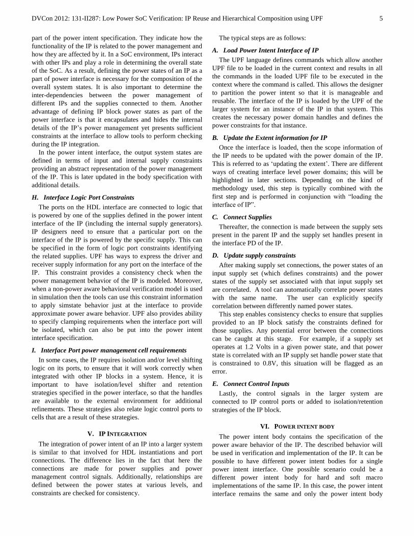
The SoC presented in Fig. 1 incorporates low power design
features and techniques that are used extensively in mobile
devices such as smart phones, tablets and notebooks. We have
chosen this example to exemplify the need and value
proposition of hierarchical UPF 2.0/2.1 methodology for
power intent definition and integration. This methodology
should follow the typical development verification and
integration flow of an SoC, in which complex designs are
defined by an architecture that integrates multiple functional
subsystems, advanced connectivity, and an array of custom
IPs and peripherals.
Figure 1. Example SoC
Defining a flat UPF power intent file to be used for
verification and implementation of an SoC is impractical,
extremely expensive, and error prone. It is desirable to have an
SoC system-level UPF that integrates subsystem UPF files,
which can be developed independently in parallel, following
the UPF system level power intent specification but defining
subsystem specific low power strategies and techniques that
can be abstracted from the SoC system-level UPF. This
provides flexibility to subsystem design teams to implement
independently the best low power strategies customized for
each specific subsystem, eliminating the complexity of
defining lower level low power strategies at the SoC UPF
system level.
The UPF hierarchical methodology addresses both soft IP
and hard IP power intent modeling and integration
DVCon 2012: 131-II287: Low Power SoC Verification: IP Reuse and Hierarchical Composition using UPF
7
requirements. For complex hard IPs such as PLLs, IO Pads,
LPDDR Phys, LDOs, SATA, and memories, it is desirable to
have complete UPF power intent models that describe all the
low power features implemented in the IP block. This goes
beyond the capabilities provided by Liberty files. Complete
definition of supply sets and power states, isolation and level
shifter strategies applied to the boundary ports, feed-throughs
and analog ports specification, internally generated supply
sets, and internal power gating can be described using hard IP
UPF models. It is required that the UPF model of a hard IP to
be a superset of the corresponding Liberty file with respect to
the power intent description.
The UPF model of a soft IP block is defined by the interface
and body UPF file. The system level UPF can use the UPF
interface definitions for each of the subsystems very early in
the design process before those subsystems are actually
implemented. This provides the flexibility to perform power
aware verification of the SoC very early in the design stage
with a simplified model and then later update the UPF body of
the subsystems when the subsystem development is
completed. In this way much more efficient divide and
conquer verification strategies can be employed.
Another major objective of the UPF hierarchical
methodology is to enable portability of UPF files across the
design process from RTL to GDS. We believe that the
proposed methodology creates the framework for a
hierarchical power aware design methodology that can be
further enhanced by future updates of the IEEE 1801 standard.
2) Structure of the design
The SoC architecture comprises of the following:
SoC top level
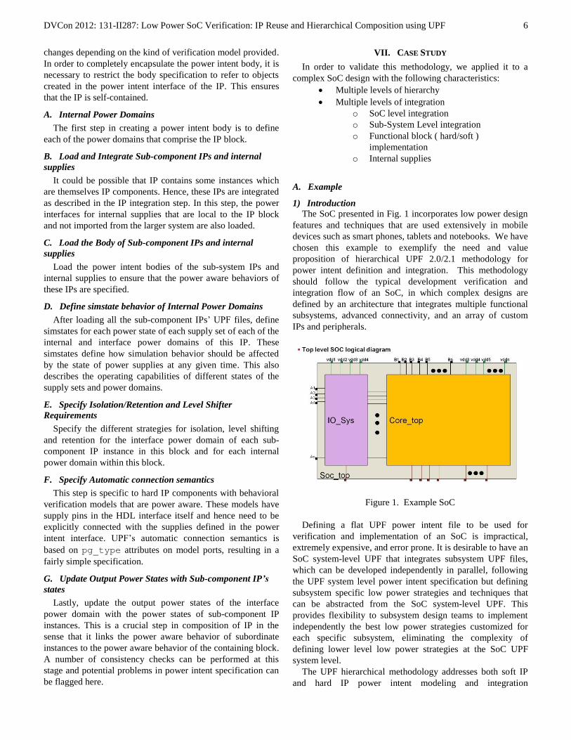
o Core_top (Figure 2)
o IO_Sys (Figure 3)
Sub-Systems
o Communication sub-system
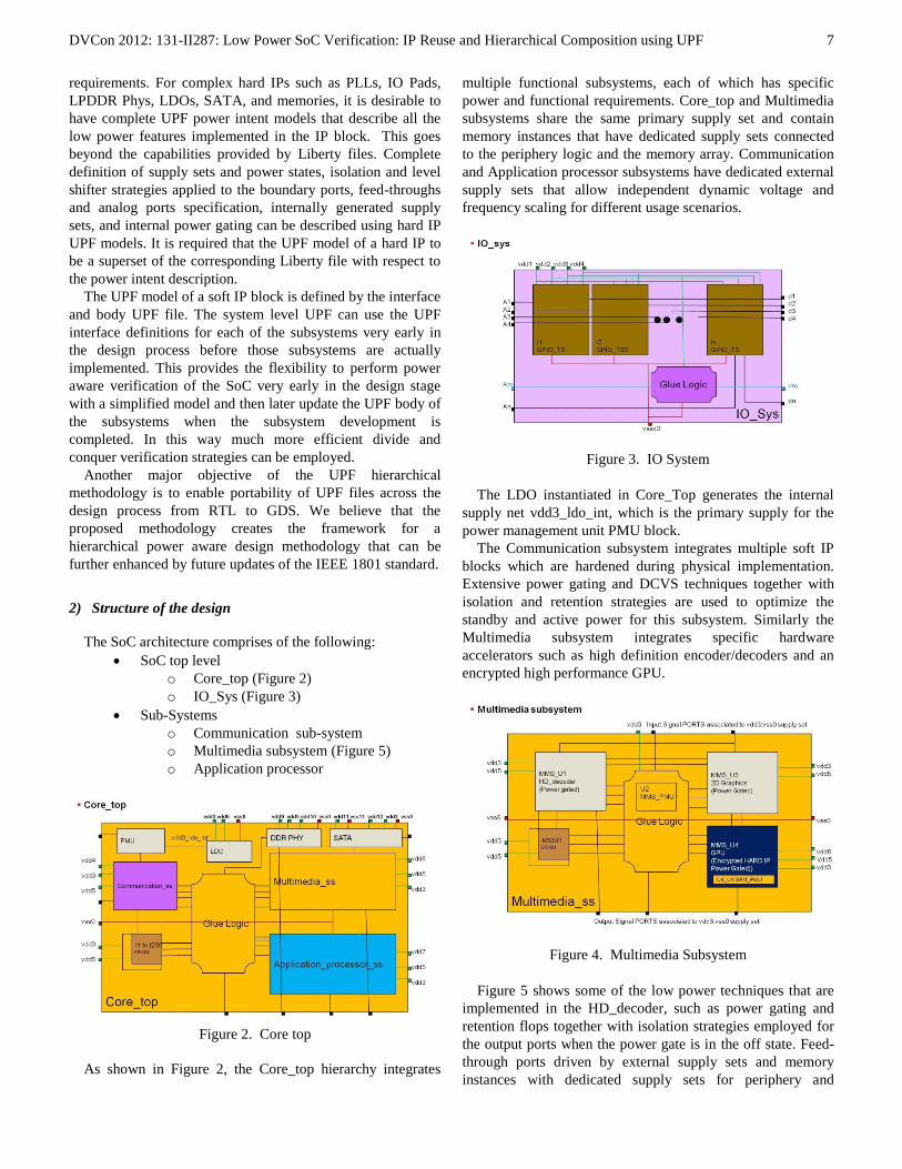
o Multimedia subsystem (Figure 5)
o Application processor
Figure 2. Core top
As shown in Figure 2, the Core_top hierarchy integrates
multiple functional subsystems, each of which has specific
power and functional requirements. Core_top and Multimedia
subsystems share the same primary supply set and contain
memory instances that have dedicated supply sets connected
to the periphery logic and the memory array. Communication
and Application processor subsystems have dedicated external
supply sets that allow independent dynamic voltage and
frequency scaling for different usage scenarios.
Figure 3. IO System
The LDO instantiated in Core_Top generates the internal
supply net vdd3_ldo_int, which is the primary supply for the
power management unit PMU block.
The Communication subsystem integrates multiple soft IP
blocks which are hardened during physical implementation.
Extensive power gating and DCVS techniques together with
isolation and retention strategies are used to optimize the
standby and active power for this subsystem. Similarly the
Multimedia subsystem integrates specific hardware
accelerators such as high definition encoder/decoders and an
encrypted high performance GPU.
Figure 4. Multimedia Subsystem
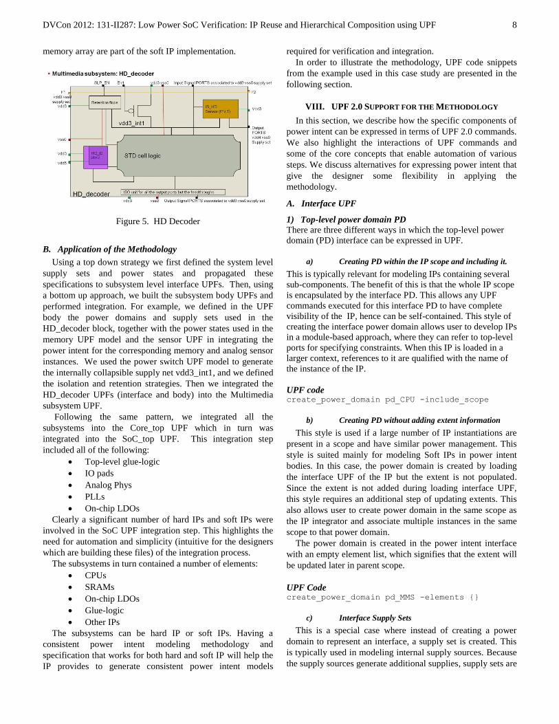
Figure 5 shows some of the low power techniques that are
implemented in the HD_decoder, such as power gating and
retention flops together with isolation strategies employed for
the output ports when the power gate is in the off state. Feed-
through ports driven by external supply sets and memory
instances with dedicated supply sets for periphery and
DVCon 2012: 131-II287: Low Power SoC Verification: IP Reuse and Hierarchical Composition using UPF
8
memory array are part of the soft IP implementation.
Figure 5. HD Decoder
B. Application of the Methodology
Using a top down strategy we first defined the system level
supply sets and power states and propagated these
specifications to subsystem level interface UPFs. Then, using
a bottom up approach, we built the subsystem body UPFs and
performed integration. For example, we defined in the UPF
body the power domains and supply sets used in the
HD_decoder block, together with the power states used in the
memory UPF model and the sensor UPF in integrating the
power intent for the corresponding memory and analog sensor
instances. We used the power switch UPF model to generate
the internally collapsible supply net vdd3_int1, and we defined
the isolation and retention strategies. Then we integrated the
HD_decoder UPFs (interface and body) into the Multimedia
subsystem UPF.
Following the same pattern, we integrated all the
subsystems into the Core_top UPF which in turn was
integrated into the SoC_top UPF. This integration step
included all of the following:
Top-level glue-logic
IO pads
Analog Phys
PLLs
On-chip LDOs
Clearly a significant number of hard IPs and soft IPs were
involved in the SoC UPF integration step. This highlights the
need for automation and simplicity (intuitive for the designers
which are building these files) of the integration process.
The subsystems in turn contained a number of elements:
CPUs
SRAMs
On-chip LDOs
Glue-logic
Other IPs
The subsystems can be hard IP or soft IPs. Having a
consistent power intent modeling methodology and
specification that works for both hard and soft IP will help the
IP provides to generate consistent power intent models
required for verification and integration.
In order to illustrate the methodology, UPF code snippets
from the example used in this case study are presented in the
following section.
VIII. UPF 2.0 SUPPORT FOR THE METHODOLOGY
In this section, we describe how the specific components of
power intent can be expressed in terms of UPF 2.0 commands.
We also highlight the interactions of UPF commands and
some of the core concepts that enable automation of various
steps. We discuss alternatives for expressing power intent that
give the designer some flexibility in applying the
methodology.
A. Interface UPF
1) Top-level power domain PD
There are three different ways in which the top-level power
domain (PD) interface can be expressed in UPF.
a) Creating PD within the IP scope and including it.
This is typically relevant for modeling IPs containing several
sub-components. The benefit of this is that the whole IP scope
is encapsulated by the interface PD. This allows any UPF
commands executed for this interface PD to have complete
visibility of the IP, hence can be self-contained. This style of
creating the interface power domain allows user to develop IPs
in a module-based approach, where they can refer to top-level
ports for specifying constraints. When this IP is loaded in a
larger context, references to it are qualified with the name of
the instance of the IP.
UPF code create_power_domain pd_CPU -include_scope
b) Creating PD without adding extent information
This style is used if a large number of IP instantiations are
present in a scope and have similar power management. This
style is suited mainly for modeling Soft IPs in power intent
bodies. In this case, the power domain is created by loading
the interface UPF of the IP but the extent is not populated.
Since the extent is not added during loading interface UPF,
this style requires an additional step of updating extents. This
also allows user to create power domain in the same scope as
the IP integrator and associate multiple instances in the same
scope to that power domain.
The power domain is created in the power intent interface
with an empty element list, which signifies that the extent will
be updated later in parent scope.
UPF Code create_power_domain pd_MMS -elements {}
c) Interface Supply Sets
This is a special case where instead of creating a power
domain to represent an interface, a supply set is created. This
is typically used in modeling internal supply sources. Because
the supply sources generate additional supplies, supply sets are
DVCon 2012: 131-II287: Low Power SoC Verification: IP Reuse and Hierarchical Composition using UPF
9
sufficient to model the power intent interface without a need
to create an explicit power domain.
UPF Code create_supply_set $ldo_op_sset
2) Input supplies
Input supplies are modeled as supply set handles of the top-
level power domain. This allows the designer to symbolically
refer to supply sets imported from higher levels of the design
hierarchy. It also restricts the inputs to the name space of the
interface PD to avoid any problem with name clashes.
UPF Code create_power_domain pd_MMS -update \
-supply { gpu_ssh } \
-supply { sram_ssh }
3) Input supply constraints
These are modeled as supply expressions for named power
states defined on input supply set handles. The specification is
done in terms of symbolic function handles, hence it doesn’t
require any supply nets to be associated with supply sets to
specify constraints. It is also possible to specify voltage ranges
in the constraints.
UPF Code add_power_state pd_MMS.primary \
-state ON_1d2V {
-supply_expr {
(pd_MMS.primary.power=={FULL_ON, 1.2}) &&
(pd_MMS.primary.ground==FULL_ON)
}
}
4) Input logic control ports
These are modeled using the create_logic_port
command in UPF.
UPF Code create_logic_port iso_ctrl
5) Internal supply constraints
These are defined by loading the interface UPF
corresponding to internal supplies. Refer to B.1 for more
details.
UPF Code # sw_op_sset is the parameter which refers to
# output supply set created in
# switch_interface.upf
# sw_ip_sset is the parameter corresponding to
# input supply set connected to switch.
# inp_ss_state_list is the list of power
# states on input supply set which will be
# added on output supply set with additional
# constraints
load_upf_protected upf/switch_interface.upf \
-params { \
{sw_op_sset ss_cd_MMS_pg_sw} \
{sw_ip_sset pd_MMS.primary} \
{inp_ss_state_list {ON_1d2V}} \
} \
-hide_globals
6) Output supplies
These are defined in the same way as for input supplies,
except that we must also associate the output supply set of an
internal supply with the appropriate supply set handle.
UPF Code create_power_domain pd_MMS -update \
-supply { sw_primary_ssh ss_cd_MMS_pg_sw }
7) Output system states
These are specified by adding power states on the interface
power domain or interface supply sets. The states are added
using the add_power_state command and the
relationship is expressed using a logic expression written in
terms of states of input supplies and internal supplies.
UPF Code add_power_state pd_MMS \
-state PD_MMS_ON {
-logic_expr {
(pd_MMS.sw_primary_ssh == ON_1d2V) &&
(pd_MMS.primary == ON_1d2V) &&
(pd_MMS.gpu_ssh == ON_1d2V) &&
(pd_MMS.sram_ssh == ON_1d2V)
}
}
8) Interface logic port constraints
These constraints are specified using the two options
–driver_supply_set and –receiver_supply_set
of the set_port_attributes command. These
constraints may be specified in different ways depending upon
the style of power domain creation used to define the
interface.
If style A.1.a is used then it is safe to directly refer to
interface ports present on the HDL interface. Since the whole
scope is included, all of the interface ports are visible.
If style A.1.b is used then it is not safe to refer to ports
directly by name when PD is not created in the same scope as
IP, as there is a possibility of multiple scopes being included
in the interface. In this case, designers can use filters and rules
to specify port constraints.
UPF Code set_port_attributes -ports { out_vdd5 } \
-driver_supply pd_MMS_GPU.vdd5_ssh
set_port_attributes -domains { pd_MMS } \
-applies_to inputs \
-receiver_supply pd_MMS.primary
DVCon 2012: 131-II287: Low Power SoC Verification: IP Reuse and Hierarchical Composition using UPF
10
9) Interface port power management cell requirements
In some cases, it is important to specify the isolation, level
shifting, and retention requirements for the top-level interface
power domain. This is typically done when there is no need to
create explicit control ports and thus we can avoid having to
explicitly connect them. A similar connection can be achieved
automatically by updating controls in the parent UPF where
control nets are visible. In such cases, the controls will be
automatically routed to the exact place they are used by
implicitly creating ports and nets and connecting them. If
strategies are specified in the interface UPF, their controls are
intentionally left unspecified so that they can be added later
while integrating the IP.
UPF Code set_isolation pd_iso_op \
-domain pd_cpu \
-clamp_value 0 \
-applies_to outputs \
-location self
set_isolation pd_iso_ip \
-domain pd_cpu \
-clamp_value 0 \
-applies_to inputs \
-location self
set_level_shifter pd_ls -domain pd_cpu
set_retention pd_ret -domain pd_cpu
B. IP Integration
1) Loading power intent interfaces
The interface UPF of each subcomponent is loaded by the
parent UPF using the load_upf_protected or
load_upf commands.
The load_upf_protected command provides
additional features such as passing the parameters and
restricting visibility of global names. This is useful when UPF
files are parameterized for reuse using Tcl variables. In such
cases, the –params option of load_upf_protected is
used to specify the value of the variables. It is generally
recommended to use the –hide_globals option when a
UPF file uses global variables and restrict the value
specification through the –params option. This avoids any
un-intended values being assigned to those variables.
For cases where a power domain is created in a subordinate
scope, the –scope option is used to automatically change the
scope to the scope in which the power domain is created.
UPF Code load_upf_protected upf/ldo_interface.upf \
-params { \
{ldo_op_sset ss_cpu0} \
{ldo_ip_sset pd_app_proc.cpu_ssh} \
} \
-hide_globals
load_upf_protected upf/cpu_interface.upf \
-params { \
pd_cpu \
} –scope cpu_i
load_upf upf/app_proc.upf \
-scope application_processor_i
2) Update the extent information for IP
This is done by invoking the create_power_domain
command with –update and –elements options. The
command must be executed in the scope in which the IP is
integrated as this scope has the visibility of the instance name
of the IP.
UPF Code create_power_domain pd_GL -update \
-elements { gl_i }
3) Connecting supplies
Supply connections are accomplished by using the UPF
associate_supply_set command. This command
associates the supply set imported from the parent context
with the IP’s supply set handle.
UPF Code associate_supply_set pd_app_proc.sw_pri_ssh \
-handle pd_GL.primary
4) Updating supply constraint
This is also done with the add_power_state command,
using the –update option to add constraints from the IP’s
input supply set.
UPF Code add_power_state pd_app_proc.sw_pri_ssh \
-update \
-state ON_1d2V { \
-logic_expr { \
( pd_GL.primary == GL_ON_1d2V ) \
} \
} \
-state OFF_STATE { \
-logic_expr { \
( pd_GL.primary == GL_OFF_STATE ) \
} \
}
5) Connecting control signals
There are two ways in which control signals can be
connected during integration of the IP.
Explicit Connection: This is done when the IP interface
contains explicit declarations of logic ports that need to be
connected. It is done using the UPF connect_logic_net
command.
Implicit Connections: This is done by updating the
controls in the strategies. This approach is used when the
strategies are defined in the power interface of the IP.
UPF Code
DVCon 2012: 131-II287: Low Power SoC Verification: IP Reuse and Hierarchical Composition using UPF
11
# Explicit Logic Connection
connect_logic_net iso_ctrl \
-ports { mms_i/iso_ctrl }
# Implicit Logic Connection
set_isolation pd_iso_op -update \
-domain pd_GL \
-isolation_signal iso_ctrl \
-isolation_sense high
C. Body UPF
1) Internal power domains
The internal power domains are created in the same way as
is done for an interface UPF. Power domains that follow
A.1.a/A.1.b are automatically created when their IPs are
loaded in the system.
UPF Code create_power_domain pd_cpu0 -elements {inst1}
2) Integration of sub-system IPs and supplies
The integration of a sub-system is performed in the same
ways as described in section B.
UPF Code # **---------------------
# ** INTEGRATE: GlueLogic
# **---------------------
# **---------------------
# ** INTEGRATE: LOAD CONSTRAINTS
# **---------------------
load_upf upf/glue_logic.upf –scope gl_i
# **---------------------
# ** INTEGRATE: UPDATE Extents
# **---------------------
# Not required already done in previous step
# **---------------------
# ** INTEGRATE: CONNECT Supplies
# **---------------------
associate_supply_set pd_app_proc.sw_pri_ssh \
-handle gl_i/pd_GL.primary
associate_supply_set pd_app_proc.primary \
-handle gl_i/pd_GL.default_isolation
associate_supply_set pd_app_proc.primary \
-handle gl_i/pd_GL.default_retention
# **---------------------
# ** INTEGRATE: UPDATE Supplies Constraints
# **---------------------
add_power_state pd_app_proc.sw_pri_ssh \
-update \
-state ON_1d2V { \
-logic_expr { \
(gl_i/pd_GL.primary == GL_ON_1d2V) \
} \
} \
-state OFF_STATE { \
-logic_expr { \
(gl_i/pd_GL.primary == GL_OFF_STATE) \
} \
}
add_power_state pd_app_proc.primary \
-update \
-state ON_1d2V { \
-logic_expr { \
(gl_i/pd_GL.default_isolation==GL_ON_1d2V)&&\
(gl_i/pd_GL.default_retention==GL_ON_1d2V) \
} \
}
# **---------------------
# ** INTEGRATE: CONNECT Logic Controls
# **---------------------
set_isolation pd_iso_op -update \
-domain gl_i/pd_GL \
-isolation_signal iso_ctrl \
-isolation_sense high
3) Load the body of sub-component IPs and supplies
The body of the power intent specification for each IP
instance and the body of the power intent specification for all
internal supplies are loaded in a similar way to their power
interface UPF. The difference here is that additional
parameters can be passed to provide the scope information to
the body UPF. Because the body UPF is intended to be loaded
only inside Power intent body of IP, the scopes within the IP
instance are visible to the parent context and can be passed to
the body UPF of the sub-component IP blocks and supplies.
UPF Code load_upf_protected upf/ldo_body.upf \
-params { \
{ldo_ip_sset pd_app_proc.cpu_ssh} \
ldo_scope \
ldo_op_sset \
} \
-hide_globals
load_upf_protected upf/cpu_body.upf \
-params { \
cpu_scope \
pd_cpu \
}
4) Defining simstate behavior of power domains
Simstates are added to the definitions of supply set power
states using the add_power_state –update command.
In this step the primary supplies of internal PDs and interface
PD are associated with input or internal supplies present in
Interface UPF before updating the simstate behavior.
UPF Code add_power_state pd_app_proc.primary \
-update \
-state ON_1d2V { \
-simstate NORMAL \
}
5) Specifying isolation/level shifter and retention
The strategies for isolation, level shifting and retention are
specified for the internal power. These strategies should refer
DVCon 2012: 131-II287: Low Power SoC Verification: IP Reuse and Hierarchical Composition using UPF
12
to controls defined in the interface or controls of any other
strategies.
UPF Code set_retention pd_ret \
-domain pd_MMS_pg \
-save_signal { ret_ctrl posedge } \
-restore_signal { ret_ctrl negedge }
set_isolation pd_iso_op \
-domain pd_MMS_pg \
-clamp_value 0 \
-applies_to outputs \
-location parent \
-isolation_signal iso_ctrl \
-isolation_sense high
set_level_shifter pd_ls \
-domain pd_MMS_pg
6) Specifying automatic connection semantics
The automatic connection semantics are specified by the
connect_supply_set command. If the domain contains
multiple supply sets, then multiple connect_supply_set
commands may be needed. Additionally, users can explicitly
associate pg_type attributes to hard macro pins if required.
UPF Code #Automatic connection semantics for
#Hard Macro Supply Connections
connect_supply_set pd_MMS_GPU.primary \
-connect { \
power {primary_power pg_gpu_vdd8} } \
-connect { \
ground {primary_ground} }
#Ground is common, so not connected again
connect_supply_set pd_MMS_GPU.vdd5_ssh \
-connect { power {pg_gpu_vdd5} }
connect_supply_set pd_MMS_GPU.vdd3_ssh \
-connect { power {pg_gpu_vdd3} }
7) Updating output power states
The system states specified in the interface UPF are now
updated to reflect the sub-component instance states. This
creates the necessary correlation between power states of the
IP block in and power states of its sub-components.
To achieve this, the add_power_state command is
used with the –update option; the power state relationships
are specified with –logic_expr.
Note that the same states are specified in the interface UPF
with logic_expr containing reference to supply sets. These
state definitions are now updated with information about
subcomponent states. This redundancy is necessary to ensure
that the whole system is working properly without violating
any constraints specified in the interface UPF. As UPF
provides an internal self-checking mechanism for the
add_power_state command any logical contradiction is
caught by tools and reported as an error. Hence, any tool
compliant with the UPF standard will catch any such issues in
a power intent specification.
UPF Code add_power_state pd_MMS -update \
-state PD_MMS_ON {
-logic_expr {
(cd_MMS_pg == PD_MMS_PG_ON)&& \
(mms_gpu_i/pd_MMS_GPU==PD_MMS_GPU_ON)&&\
(pd_SRAM == PD_SRAM_ON) \
} \
}
IX. SUMMARY
With the increasing complexity of today’s SoCs, power
management has become a critical aspect of the design
process, one that cannot be ignored due to its potential impact
on overall functionality. A typical SoC consists of various IPs
each performing some specific functionality along with its
own power management strategy. In some IPs the power
management can become quite complex involving multiple
power domains with different power requirements. Integrating
multiple IPs into a SoC, while maintaining correctness of the
power management structures, and ensuring that no functional
issues are introduced in the process, can be very challenging.
Reuse and hierarchical composition are an integral part of
any SoC design. It is very difficult to reason clearly about the
interaction of functionality and power management using a
flat model of the two. A methodology that supports
hierarchical composition and reuse of power intent along with
functionality is required. Automation of tedious tasks involved
in IP integration is also important to minimize human
interaction and chances of human error.
In this paper, we have shown how designers can express
their power intent using UPF 2.0 capabilities in the context of
a hierarchical methodology that helps ensure correctness at
both IP and system levels. The methodology addresses the
power management requirements of both soft IP and hard IP
blocks. The methods presented in the paper enable tools to
automate connection and routing of supplies to the appropriate
domains as well as verification of power constraints as each IP
block is integrated, to ensure coherency of the power intent at
various levels of the SoC development.
X. FUTURE WORK
Although the methodology described in this paper can be
used effectively with UPF 2.0, some improvements may
become possible as UPF continues to evolve.
One area of potential improvement is in the use of the
add_power_state command. In UPF 2.0, this command
can be used to define power states of supply sets or power
domains. However, there is no syntax to indicate which of the
two uses is involved in a given command. Furthermore, there
are two uses of power domains in this methodology: one to
model real power domains in the design, the other to model
the interface to an IP block, so that supply sets can be passed
into the UPF specification for the interface of that block. Here
again there is no syntactic differentiation between these two
cases. A possible enhancement to UPF would be to add a
DVCon 2012: 131-II287: Low Power SoC Verification: IP Reuse and Hierarchical Composition using UPF
13
qualifier to distinguish these three applications. With such a
qualifier, additional automation or constraint checking would
become possible, and supply expressions used to define some
power states could potentially be simplified.
Another area of potential improvement is in the handling of
control signals. Supply set parameters to a UPF interface
specification are defined as supply set handles associated with
the top-level power domain, but this approach does not work
for control signals, which instead must be defined as logic
ports on the top-level module of the IP block. Since the top-
level power domain is functioning as the power interface to
the IP block, it would be convenient to be able to associate
control inputs with that interface as well, and refer to them in
much the same way that supply set handles are referred to.
Unifying the power interface to include both supply sets and
control signals would help streamline the methodology and
make it more consistent.
These are only two areas in which enhancements to UPF
could help improve the hierarchical methodology presented in
this paper. As users gain experience with application of this
methodology to large complex SoC designs, additional areas
of potential improvement will likely be identified.
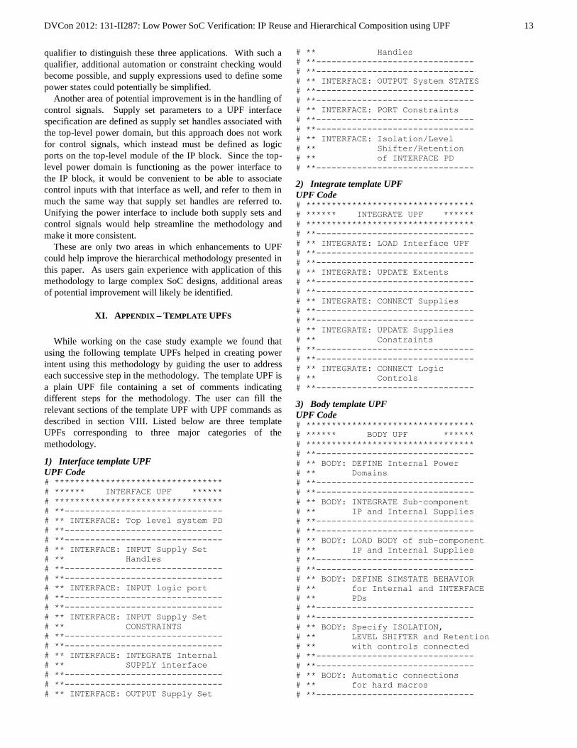
XI. APPENDIX – TEMPLATE UPFS
While working on the case study example we found that
using the following template UPFs helped in creating power
intent using this methodology by guiding the user to address
each successive step in the methodology. The template UPF is
a plain UPF file containing a set of comments indicating
different steps for the methodology. The user can fill the
relevant sections of the template UPF with UPF commands as
described in section VIII. Listed below are three template
UPFs corresponding to three major categories of the
methodology.
1) Interface template UPF
UPF Code # *********************************
# ****** INTERFACE UPF ******
# *********************************
# **-------------------------------
# ** INTERFACE: Top level system PD
# **-------------------------------
# **-------------------------------
# ** INTERFACE: INPUT Supply Set
# ** Handles
# **-------------------------------
# **-------------------------------
# ** INTERFACE: INPUT logic port
# **-------------------------------
# **-------------------------------
# ** INTERFACE: INPUT Supply Set
# ** CONSTRAINTS
# **-------------------------------
# **-------------------------------
# ** INTERFACE: INTEGRATE Internal
# ** SUPPLY interface
# **-------------------------------
# **-------------------------------
# ** INTERFACE: OUTPUT Supply Set
# ** Handles
# **-------------------------------
# **-------------------------------
# ** INTERFACE: OUTPUT System STATES
# **-------------------------------
# **-------------------------------
# ** INTERFACE: PORT Constraints
# **-------------------------------
# **-------------------------------
# ** INTERFACE: Isolation/Level
# ** Shifter/Retention
# ** of INTERFACE PD
# **-------------------------------
2) Integrate template UPF
UPF Code # *********************************
# ****** INTEGRATE UPF ******
# *********************************
# **-------------------------------
# ** INTEGRATE: LOAD Interface UPF
# **-------------------------------
# **-------------------------------
# ** INTEGRATE: UPDATE Extents
# **-------------------------------
# **-------------------------------
# ** INTEGRATE: CONNECT Supplies
# **-------------------------------
# **-------------------------------
# ** INTEGRATE: UPDATE Supplies
# ** Constraints
# **-------------------------------
# **-------------------------------
# ** INTEGRATE: CONNECT Logic
# ** Controls
# **-------------------------------
3) Body template UPF
UPF Code # *********************************
# ****** BODY UPF ******
# *********************************
# **-------------------------------
# ** BODY: DEFINE Internal Power
# ** Domains
# **-------------------------------
# **-------------------------------
# ** BODY: INTEGRATE Sub-component
# ** IP and Internal Supplies
# **-------------------------------
# **-------------------------------
# ** BODY: LOAD BODY of sub-component
# ** IP and Internal Supplies
# **-------------------------------
# **-------------------------------
# ** BODY: DEFINE SIMSTATE BEHAVIOR
# ** for Internal and INTERFACE
# ** PDs
# **-------------------------------
# **-------------------------------
# ** BODY: Specify ISOLATION,
# ** LEVEL SHIFTER and Retention
# ** with controls connected
# **-------------------------------
# **-------------------------------
# ** BODY: Automatic connections
# ** for hard macros
# **-------------------------------
DVCon 2012: 131-II287: Low Power SoC Verification: IP Reuse and Hierarchical Composition using UPF
14
# **-------------------------------
# ** BODY: Update SYSTEM STATES
# ** based on sub-component IP
# **-------------------------------
ACKNOWLEDGMENTS
The authors wish to acknowledge the valuable input from
many discussions with members of the IEEE P1801 (UPF)
working group regarding the requirements for hierarchical
UPF methodology and the potential methods for supporting
hierarchical power intent specifications. Those discussions
contributed significantly to our understanding of what is
possible in UPF 2.0 and helped lead to the methodology
described herein.
REFERENCES
[1] W. Wolf, Modern VLSI Design: IP-Based Design, Prentice Hall, New
York, NY, USA, 2008. [2] IEEE Std 1801™-2009 for Design and Verification of Low Power
Integrated Circuits. IEEE Computer Society, 27 March 2009.
[3] Keating, M., Flynn, D., et al. Low Power Methodology Manual for System on Chip Design. Chapter 2, Standard Low Power Methods.
Springer, 2007.
[4] Svendsen, K., Seeley, C., Marschner, E., Achieving First-Time Success with a UPF-based Low Power Verification Flow, DVCon 2011,
February 2011.
[5] Yeung, P., and Marschner, E., Power-Aware Verification of ARM-Based Designs, ARM TechCon 2011.
[6] Freddy Bembaron, Rudra Mukherjee, Amit Srivastava and Sachin
Kakkar : “Low Power Verification Methodology using UPF.”, DVCon 2009.
[7] Rudra Mukherjee, Amit Srivastava, Stephen Bailey: “Static and Formal Verification of Low Power Designs at RTL using UPF”, DVCon 2008.
[8] Stephen Bailey, Amit Srivastava, Mark Gorrie, Rudra Mukherjee: “To
Retain or Not to Retain: How do I verify the states of my low power
design”, DVCon 2008.