Embed Size (px)
Citation preview
Low-loss ultrabroadband 90° optical rotator withcollinear input and output beams
Roland K. Appel and Chris D. Dyer
An achromatic device to rotate optical polarization by 90° is described. This is based on a series ofreflecting surfaces that rotates incoming light about the optical axis and translates it such that the exitinglight is collinear. Polarization rotation is achieved by rotation of the optical beam, as opposed to themore common approach of phase retardation by use of birefringent elements. For broadband operationfrom the UV to the near infrared, the device was constructed by use of total internal reflection in threefused-silica glass components. Losses are minimized with interstitial surfaces designed to be angledclose to Brewster’s angle.
OCIS codes: 120.4570, 120.5410, 220.1000, 230.5440, 230.5480, 260.5430.
1. Introduction
There are many applications in which it is desirableto rotate the plane of polarization of light through90°. These include spectroscopy, where polarizationholds key information; interferometry, where the ref-erence beam may be required to be rotated by 90° tosee the cross-polarized components; and quantitativemetrology applications, where measurements are tobe made at 0° and 90°.
Optical polarization is commonly rotated by use ofa wave plate. This exploits the birefringence of anoptical material to impose the required phase shiftbetween the orthogonally polarized components ofthe light. Individual half-wave plates are effectiveonly over a narrow wavelength range, so that a largenumber of plates would be required to cover a widewavelength range. Moreover this approach does notenable simultaneous broadband coverage. Super-achromatic wave plates that facilitate extendedwavelength coverage can be designed. This type ofwave plate is akin to a lens doublet, exploiting thedifferential birefringence of two or more materials.Nevertheless, achromatic wave plates have a numberof drawbacks. The constituent optical elements maybe contacted with optical cement, limiting the opticalpower throughput. Moreover, because of the natu-rally large dispersion of most optical materials in the
R. K. Appel �[email protected]� is with QinetiQ, 1026�A5,Ively Road, Farnborough GU14 0LX, UK. C. D. Dyer is with Dstl,Porton Down, Salisbury SP4 0JQ, UK.
Received 27 August 2001; revised manuscript received 14 De-cember 2001.
1888 APPLIED OPTICS � Vol. 41, No. 10 � 1 April 2002
UV, chromatic correction is limited to some tens ofnanometers or less at wavelengths below �300 nm.
Optical polarization can also be rotated by Fresnelrhombs, which achieve retardation by exploiting thephase difference imposed on s- and p-polarized lightupon total internal reflection �TIR�. This phase shifthas a relatively slow variation with wavelength com-pared with the performance of a wave plate. Nev-ertheless, the performance is not achromatic; forexample, a pair of silica Fresnel rhombs designed forhalf-wave operation impose a phase retardation of180° � 8° over the wavelength range 200–400 nm.The deviation from exactly 180° of phase retardationresults in the light becoming elliptically polarized.
Full achromatic rotation of the optical polarizationcan be achieved with a succession of reflectors,1–7
such that the light incident at each is either pure s orp polarized. This prevents mixing between orthog-onal polarization components. The approach is fun-damentally different from the wave plate and Fresnelrhomb. The polarization rotation is achieved by ro-tating the optical beam about the optical axis. Thiscan be seen as a geometrical optics approach and isfully achromatic.
The method relies on a succession of reflectionsthat can be carried out by use of mirrors or prisms.Three reflections rotate the polarization, generatingan optical beam that lies parallel to the original beampath; four further reflections return the beam to becollinear with the input. The total number of nec-essary reflections is thus seven. Our applications8,9
require an optical rotator to operate from the UV �200nm� into the near IR �700 nm�. Broadband high-reflectance mirrors are not available over this range,
so that it is necessary to use the TIR of prism ele-ments. Reflection efficiencies are high, but the en-trance and exit faces of each prism introduceadditional losses. Previous published rotator devic-es7 minimize such losses by applying antireflectioncoatings to the input and output surfaces of a series ofright-angle prisms. Broadband coatings, however,are not available for operation over the full waveband of 200–700 nm, making this approach inappro-priate for our own application.
In this paper we describe a device in which lossesare significantly reduced without use of optical coat-ings. We achieved the reduction by constructing thedevice with only three constituent component ele-ments, thereby limiting interstices to two. Further-more, these are orientated at Brewster’s angle. InSection 2 we discuss the principal of operation; inSection 3 we describe the device that has been con-structed and report on the test results.
2. Principle of Operation
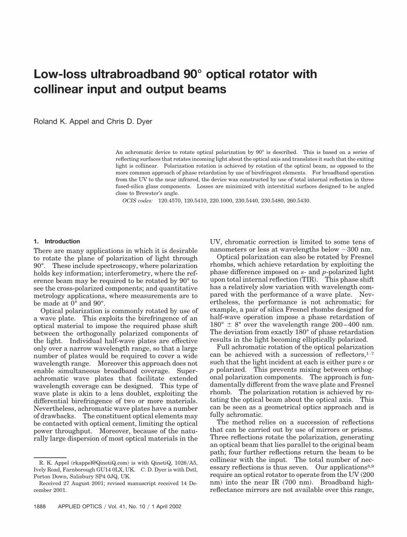
Figure 1�a� shows an optical arrangement by whichlight can be rotated by a succession of reflections.The incident beam propagates along the z axis; eachreflection is at exactly 90°, causing the beam to bedeflected into the x and y directions before finallyemerging from the device collinear with the input.The orientation of the beam is indicated on the sche-matic by a double-ended arrow and dumbbell, so thatafter seven reflections the beam can be seen to berotated by 90°. In this way, a polarized incomingbeam will likewise have its polarization rotatedthrough 90°. TIR imposes different phase shifts10
on p- and s-polarized light, the phase shift also beinga function of wavelength. To ensure that the trans-mitted light remains polarized, it is necessary thatthe incident light be linearly polarized along only oneof the axes x and y.
The first three reflections, designated 1–3 in Fig.1�a� are in orthogonal planes, thereby causing rota-tion of the beam and hence the polarization throughexactly 90°. The reflections 4–5 and 6–7 translatethe beam along the y and x axes, respectively, so thatthe light emerges from the device collinear with theincident beam. There are of course other arrange-ments for the successive reflections: Fig. 1�b� showsanother possible ordering. In this example, polar-ization rotation is accomplished by the three succes-sive reflections on surfaces 4, 5, and 6.
The rotator device can be constructed from individ-ual right-angle prisms. We are not aware of anysuitable low-absorption optical cements available foruse in the far UV, so the prisms are either opticallycontacted �which is difficult to achieve while main-taining the required alignment� or air coupled. Theoverall reflection losses for a device constructed ofseven individual air-coupled prisms is, however,�50% at 200 nm �with fused-silica prisms�.
Building the device with fewer component prismsreduces the reflection losses. The ideal solution isfor the device to be manufactured out of a single blockof material. However, this is not possible because
there is always at least one inner surface that isunable to be polished, for example, surface 5 in Fig.1�a�: this surface cannot be polished because of thepresence of surfaces 1, 2, and 3. The approach wetook was to manufacture the device out of three com-ponent parts. The component parts contained sur-faces 1–3, 4–5, and 6–7.
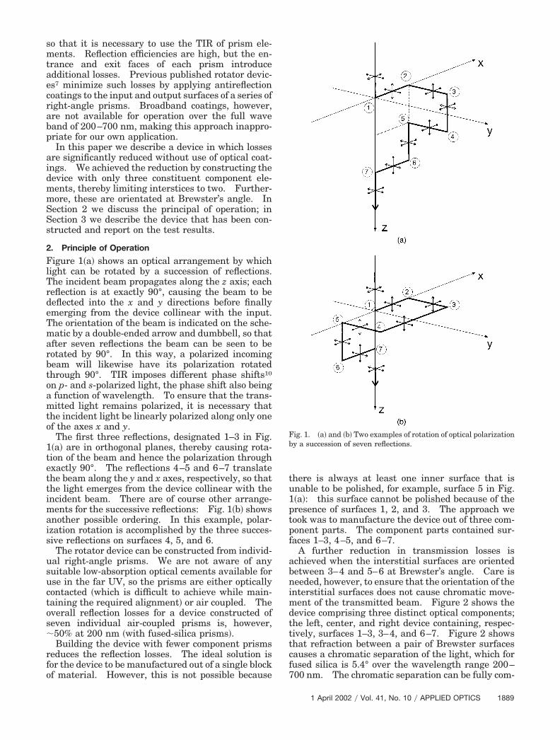
A further reduction in transmission losses isachieved when the interstitial surfaces are orientedbetween 3–4 and 5–6 at Brewster’s angle. Care isneeded, however, to ensure that the orientation of theinterstitial surfaces does not cause chromatic move-ment of the transmitted beam. Figure 2 shows thedevice comprising three distinct optical components;the left, center, and right device containing, respec-tively, surfaces 1–3, 3–4, and 6–7. Figure 2 showsthat refraction between a pair of Brewster surfacescauses a chromatic separation of the light, which forfused silica is 5.4° over the wavelength range 200–700 nm. The chromatic separation can be fully com-
Fig. 1. �a� and �b� Two examples of rotation of optical polarizationby a succession of seven reflections.
1 April 2002 � Vol. 41, No. 10 � APPLIED OPTICS 1889
pensated with a pair of equal-spaced interstitialBrewster surfaces. It is crucial that the surfaces areangled so as to cancel the chromatic separation: In-correct orientation of the surfaces may cause thechromatic separation to increase.
Brewster’s angle is wavelength dependent so thatthe interstitial surfaces cannot meet the exact Brew-ster condition for all wavelengths. Instead, it is nec-essary to choose an angle that most closely meets thecondition. For light propagating through an air–glass interface, the intensity reflection coefficient forp-polarized light is11
R �tan2(�1 � �0)tan2(�1 � �0)
, (1)
where �0 and �1 are the angles of refraction on, re-spectively, the air and glass side of the interface rel-ative to the surface normal. These are relatedthrough the refractive index �n1� of the glass11:
sin �0 � n1 sin �1 . (2)
The reflectivity per surface has been calculated byuse of the refractive index for fused-silica glass.12
Results are shown in Fig. 3 for the interstitial Brew-ster surfaces at three different angles, correspondingto �1 � 33° 15�, 33° 30�, and 33° 45�. We can see fromthe results that, for each value of �1, the reflectioncoefficient drops to zero at one particular wavelength:This coincides with the Brewster condition being fully
satisfied. S-polarized light does not exhibit this nullpoint.11
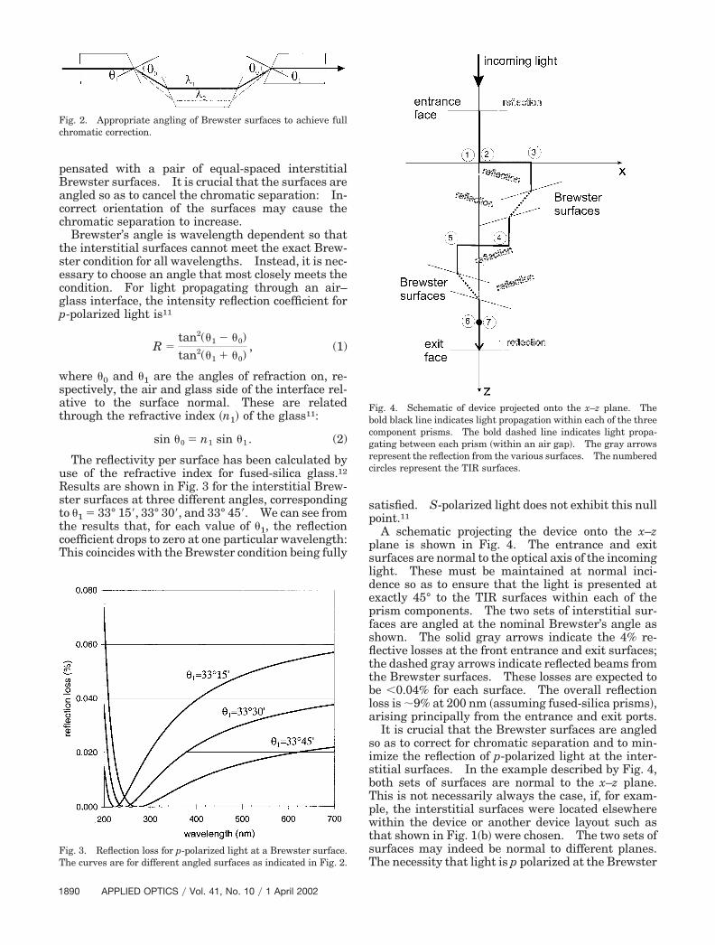
A schematic projecting the device onto the x–zplane is shown in Fig. 4. The entrance and exitsurfaces are normal to the optical axis of the incominglight. These must be maintained at normal inci-dence so as to ensure that the light is presented atexactly 45° to the TIR surfaces within each of theprism components. The two sets of interstitial sur-faces are angled at the nominal Brewster’s angle asshown. The solid gray arrows indicate the 4% re-flective losses at the front entrance and exit surfaces;the dashed gray arrows indicate reflected beams fromthe Brewster surfaces. These losses are expected tobe �0.04% for each surface. The overall reflectionloss is �9% at 200 nm �assuming fused-silica prisms�,arising principally from the entrance and exit ports.
It is crucial that the Brewster surfaces are angledso as to correct for chromatic separation and to min-imize the reflection of p-polarized light at the inter-stitial surfaces. In the example described by Fig. 4,both sets of surfaces are normal to the x–z plane.This is not necessarily always the case, if, for exam-ple, the interstitial surfaces were located elsewherewithin the device or another device layout such asthat shown in Fig. 1�b� were chosen. The two sets ofsurfaces may indeed be normal to different planes.The necessity that light is p polarized at the Brewster
Fig. 2. Appropriate angling of Brewster surfaces to achieve fullchromatic correction.
Fig. 3. Reflection loss for p-polarized light at a Brewster surface.The curves are for different angled surfaces as indicated in Fig. 2.
Fig. 4. Schematic of device projected onto the x–z plane. Thebold black line indicates light propagation within each of the threecomponent prisms. The bold dashed line indicates light propa-gating between each prism �within an air gap�. The gray arrowsrepresent the reflection from the various surfaces. The numberedcircles represent the TIR surfaces.
1890 APPLIED OPTICS � Vol. 41, No. 10 � 1 April 2002
surfaces has the consequence that the polarizer rota-tor device operates efficiently only for light of a singleinput polarization.
3. Construction and Testing of the Device
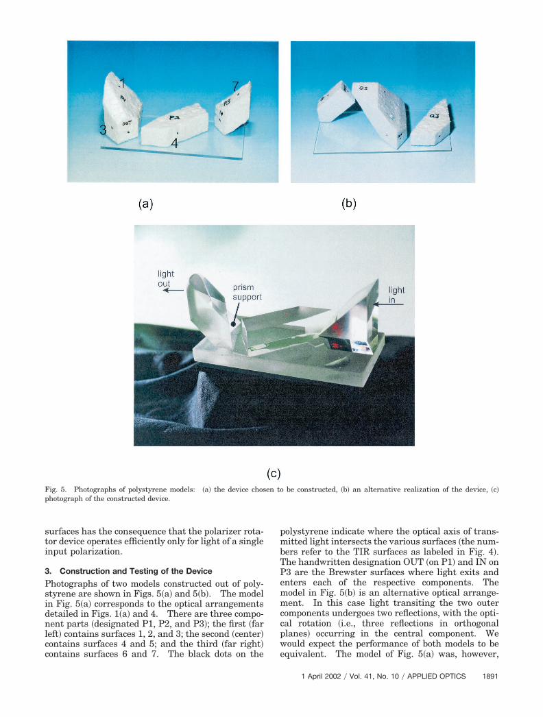
Photographs of two models constructed out of poly-styrene are shown in Figs. 5�a� and 5�b�. The modelin Fig. 5�a� corresponds to the optical arrangementsdetailed in Figs. 1�a� and 4. There are three compo-nent parts �designated P1, P2, and P3�; the first �farleft� contains surfaces 1, 2, and 3; the second �center�contains surfaces 4 and 5; and the third �far right�contains surfaces 6 and 7. The black dots on the
polystyrene indicate where the optical axis of trans-mitted light intersects the various surfaces �the num-bers refer to the TIR surfaces as labeled in Fig. 4�.The handwritten designation OUT �on P1� and IN onP3 are the Brewster surfaces where light exits andenters each of the respective components. Themodel in Fig. 5�b� is an alternative optical arrange-ment. In this case light transiting the two outercomponents undergoes two reflections, with the opti-cal rotation �i.e., three reflections in orthogonalplanes� occurring in the central component. Wewould expect the performance of both models to beequivalent. The model of Fig. 5�a� was, however,
Fig. 5. Photographs of polystyrene models: �a� the device chosen to be constructed, �b� an alternative realization of the device, �c�photograph of the constructed device.
1 April 2002 � Vol. 41, No. 10 � APPLIED OPTICS 1891
chosen for construction because the volume of glass isless for a given transmission aperture.
A photograph of the constructed device is shown inFig. 5�c�. The component prisms were manufac-tured by Optical Works Ltd., Newquay, UK, and thedevice assembled jointly with Optical Works person-nel. The view is from the reverse side of the devicecompared with that shown in Fig. 5�a�. The threeseparate fused-silica prism components were manu-factured and mounted on a fused-silica-based plate.A small right-angle prism is used to mechanicallysupport the third element P3 as indicated in Fig. 5�c�.During this photographic exposure, a He–Ne laserwas directed into the device, and faint red dots can beseen where the light is scattered from the various TIRsurfaces. There is a cluster of red on the far rightelement �P1� that is caused by laser light being scat-tered into the camera during a long time exposureand is thus an artifact of the photograph.
The entrance face is 20 mm 20 mm, and there isa 10-mm gap separating the Brewster surfaces, suf-ficient to facilitate the cleaning of these surfaces ifrequired; the overall dimension of the device is 120mm 60 mm 60 mm. We aligned the componentsusing an autocollimator, and they were fixed in placeusing a UV curing adhesive. The interstitial sur-faces were polished at an angle of �1 � 33° 30�, withthe design reflectance per surface expected to be�0.04% over the wavelength range 200–700 nm; theTIR surfaces are all at 45° to the optical axis. Thedesign tolerance for each of the optical surfaces is�30 arc sec.
Any polarization cross coupling within the device ismost likely to arise at the TIR surfaces rather thanthe Brewster surfaces �assuming that cross couplingis due to surface roughness�. The phase difference imposed on the p and s TIR components is given bythe expression10
tan���
2�
cos �1�sin2 �1 � 1�n1����2�1�2
sin2 �1. (3)
To assess the depolarization caused by reflectionfrom a misaligned surface, let us consider light that istotal internally reflected at a surface that has anangular error of ε. During the reflection process, theincident beam has fractional components, sin ε andcos ε, in orthogonal polarization states. This is theworst case that may arise from a manufacture errorof ε. The actual splitting ratio depends on the direc-tion in which the surface is misorientated.
There is a phase difference imposed on the twopolarized components according to Eq. �3�. The ef-fect of the phase delay is to cause the sin ε compo-nent to have its polarization vector rotated relative tothe cos ε component. If this phase difference werezero � � 0�, then there would be no overall change inthe polarization state of the reflected beam. A non-zero value for results in a small intensity of theorthogonal polarized state being introduced into thereflected beam. The net effect is that the reflectedbeam is no longer linearly polarized but rather ellip-
tically polarized. The worst case is for this fractionto be equal to sin of the sin ε component. Hencethe fractional intensity of light transformed into theorthogonal state is �sin ε sin �. After N reflections,the fractional intensity of light transformed into theorthogonal polarization is �N sin ε sin �. N is equalto 7 for the device discussed in this paper.
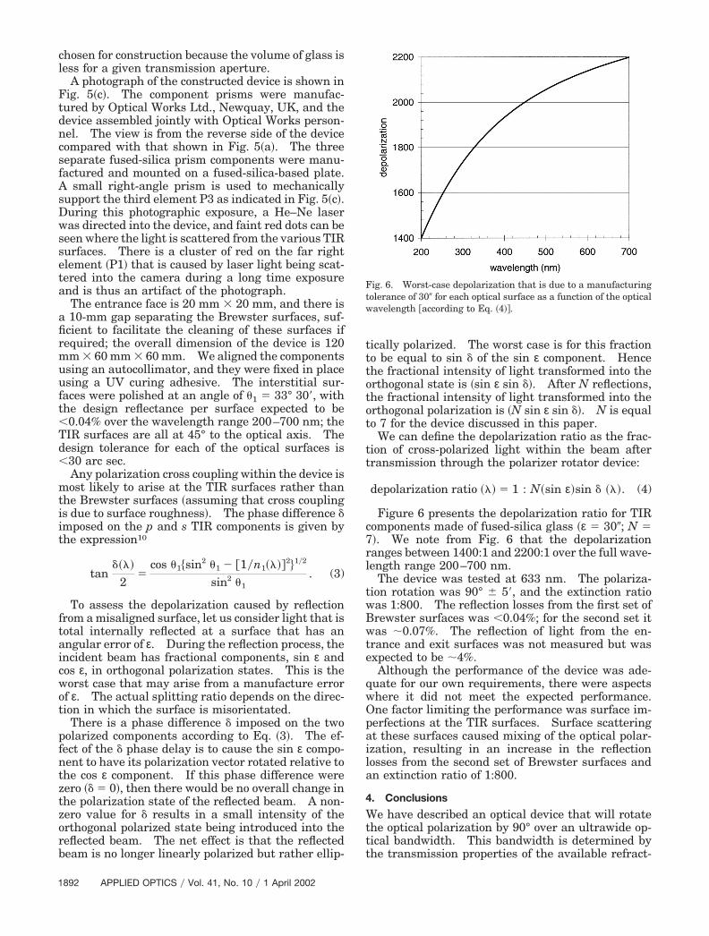
We can define the depolarization ratio as the frac-tion of cross-polarized light within the beam aftertransmission through the polarizer rotator device:
depolarization ratio ��� � 1 : N�sin ε�sin ���. (4)
Figure 6 presents the depolarization ratio for TIRcomponents made of fused-silica glass �ε � 30�; N �7�. We note from Fig. 6 that the depolarizationranges between 1400:1 and 2200:1 over the full wave-length range 200–700 nm.
The device was tested at 633 nm. The polariza-tion rotation was 90° � 5�, and the extinction ratiowas 1:800. The reflection losses from the first set ofBrewster surfaces was �0.04%; for the second set itwas �0.07%. The reflection of light from the en-trance and exit surfaces was not measured but wasexpected to be �4%.
Although the performance of the device was ade-quate for our own requirements, there were aspectswhere it did not meet the expected performance.One factor limiting the performance was surface im-perfections at the TIR surfaces. Surface scatteringat these surfaces caused mixing of the optical polar-ization, resulting in an increase in the reflectionlosses from the second set of Brewster surfaces andan extinction ratio of 1:800.
4. Conclusions
We have described an optical device that will rotatethe optical polarization by 90° over an ultrawide op-tical bandwidth. This bandwidth is determined bythe transmission properties of the available refract-
Fig. 6. Worst-case depolarization that is due to a manufacturingtolerance of 30� for each optical surface as a function of the opticalwavelength according to Eq. �4��.
1892 APPLIED OPTICS � Vol. 41, No. 10 � 1 April 2002
ing materials, which for fused silica is from the far UVto the IR. Low transmission losses are achievedwhen all interstitial surfaces are oriented at Brew-ster’s angle, so that the theoretical losses are �9%,compared with a value of �50% for a comparable de-vice constructed with standard right-angle prism com-ponents. The device has been constructed and tested.Polarization rotation was 90° � 5� and the polarizationextinction ratio was 1:800. Although this was suffi-cient for our own requirements, it is less than expected.We believe that performance is currently limited bypolarization mixing at the TIR surfaces, and we expectfurther improvements in performance by increasingthe surface quality of these surfaces.
This research was carried out within the Ministryof Defence Corporate Research Programme technol-ogy group 2, project number 02�03�02�801�1998.We acknowledge Eric Frisk of Optical Works Ltd. forinvaluable and detailed advice on the constructionand manufacture of the device. We also thank Du-leep Wickramasinghe for the technical guidancegiven to the program.
References1. I. Filinski and T. Skettrup, “Achromatic phase retarders con-
structed from right-angle prisms: design,” Appl. Opt. 23,2747–2751 �1984�.
2. T. F. Thonn and R. M. A. Azzam, “Three-reflection halfwaveand quarterwave retarders using dielectric-coated metallicmirrors,” Appl. Opt. 23, 2752–2759 �1984�.
3. N. N. Nagib and M. S. El-Bahrawy, “Phase retarders withvariable angles of total internal reflection,” Appl. Opt. 33,1218–1222 �1994�.
4. R. Bhandari, “Polarization of light and topological phases,”Phys. Rep. 281, 1–64 �1997�.
5. S.-M. F. Nee, C. Yoo, T. Cole, and D. Burge, “Characterizationfor imperfect polarizers under imperfect conditions,” Appl.Opt. 37, 54–64 �1998�.
6. N. N. Nagib, “Phase retarders highly insensitive to the inputangle,” Appl. Opt. 37, 1231–1235 �1998�.
7. F. J. Duarte, “Beam transmission characteristics of a collinearpolarization rotator,” Appl. Opt. 31, 3377–3378 �1992�.
8. R. K. Appel, C. D. Dyer, A. W. Jones, and J. N. Lockwood,“Enhanced Raman spectroscopy using collection optics de-signed for continuously tunable excitation,” Meas. Sci. Tech-nol. 13, 411–420 �2002�.
9. R. K. Appel, C. D. Dyer, J. N. Lockwood, and A. J. Bell, “Ultra-broadband collection and illumination optics for Raman andphotoluminescence spectroscopy in the 200–700 nm wave-band,” Rev. Sci. Instrum. 73 �to be published�.
10. M. Born and E. Wolf, Principles of Optics, 7th ed. �CambridgeU. Press, Cambridge, UK, 1999�.
11. E. Hecht and A. Zajac, Optics �Addison-Wesley, Reading,Mass., 1974�.
12. M. Bass, ed., Handbook of Optics �McGraw-Hill, New York,1995�, Vol. 2.
1 April 2002 � Vol. 41, No. 10 � APPLIED OPTICS 1893