Embed Size (px)
Citation preview

NIHONBASHI FRONT BLDG. 6-2 NIHONBASHI 3-CHOME CHUO-KU TOKYO 103-8306 JAPANTel.: + 81 3 6366 7731, Fax: +81 3 3270 1776
https://tokyorope-intl.co.jpE-mail: [email protected]
Innovative HTLS Transmission Conductor With Core®About Tokyo Rope Group
Tokyo Rope was established in 1887 and has been the leader in Japan's wire rope industry. Our global operations are expanding. Our main products are Steel Wire Rope, Fiber Rope, Steel Cord for tire, and CFCC.
Japan Head Office●Kitakami CFCC Plant●Tsuchiura Plant●Kitakami Plant●Kitakami Works●Sakai Plant●Tokyo Seiko Rope●Ako Rope
China●Shanghai office●Hong Kong office
Kazakhstan●Almaty Plant
Kyrgyzstan●Bishkek office
Thailand●Bangkok Office
Vietnam●Binh Duong Plant
Brazil●Sao Paulo Office
USA●Michigan CFCC Plant●Michigan Office (TOKYO ROPE USA INC.)
Russia●Moscow Office●St. Petersburg Plant●St. Petersburg Office
19-10-SA
Low Loss
High Capacity
Low Sag
8 1
TOKYO ROPE INTERNATIONAL
TOKYO ROPE INTERNATIONAL
ALUMINUM CONDUCTOR FIBER REINFORCED
®

Today's Overhead Conductor's market
Current Status
ACSR is a conventional type of conductor which has three drawbacks as follows:
●Heavy steel core●Large Thermal Expansion●Corrosion
ChallengeTransmission Owners are facing the following requirements:
●Huge Electric Demand●Environmental Concern(CO2)●Sag Violations●Right of Way Issue●Construction Cost & Period●Lower Life Cycle Cost
Annealed Aluminum Wire(or TAL / Hard Drawn Wire)
ACFR Structure
ACFR stands for Aluminum Conductor Fiber Reinforced
Core
Core
Light Weight and Small Thermal Expansion
Solution
Next generation conductor cable=
●Low Transmission Loss●High Transmission Capacity●Low Sag●Longevity●Easy Handling
Trapezoidal Shape
Trapezoidal Aluminum Wire Large Cross Sectional Area
2 3
ALUMINUM CONDUCTOR FIBER REINFORCED
®
®
The following is standard ACFR Design Example. Final design should be agreed with the conductor's manufacturer.
Standard ACFR Design Example
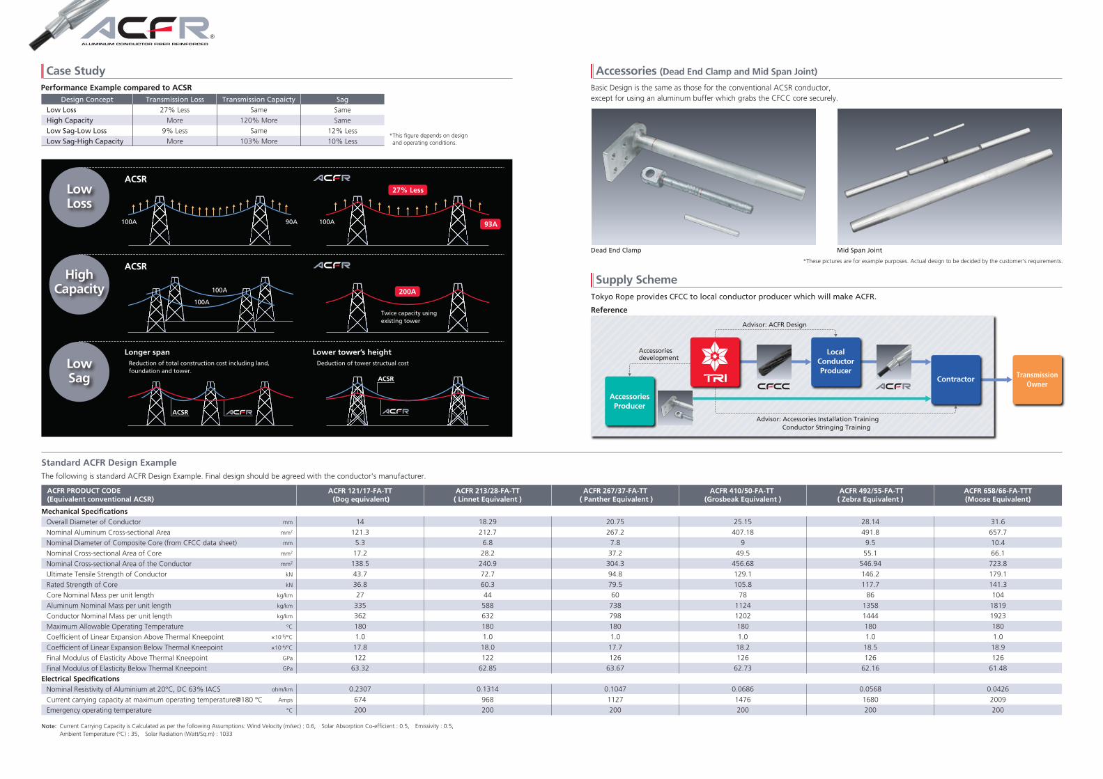
Performance Example compared to ACSR
Design Concept Transmission Loss Transmission Capaicty Sag
Low Loss
High Capacity
Low Sag-Low Loss
Low Sag-High Capacity
27% Less
More
9% Less
More
Same
120% More
Same
103% More
Same
Same
12% Less
10% Less
Case Study Accessories (Dead End Clamp and Mid Span Joint)
Supply SchemeHighCapacity
LowSag
*This figure depends on design and operating conditions.
Basic Design is the same as those for the conventional ACSR conductor, except for using an aluminum buffer which grabs the CFCC core securely.
Tokyo Rope provides CFCC to local conductor producer which will make ACFR.
ALUMINUM CONDUCTOR FIBER REINFORCED
Reference
LocalConductorProducer
Advisor: ACFR Design
Accessoriesdevelopment
Advisor: Accessories Installation TrainingConductor Stringing Training
TransmissionOwner
Contractor
AccessoriesProducer
*These pictures are for example purposes. Actual design to be decided by the customer's requirements.
Dead End Clamp Mid Span Joint
Reduction of total construction cost including land, foundation and tower.
LowLoss
ACSR
100A 90A 100A
27% Less
ACSR
ACSR
ACSR
Longer spanDeduction of tower structual cost
Lower tower’s height
100A
100A
200A
93A
Twice capacity usingexisting tower
4 5
®
Mechanical Specifications
Overall Diameter of Conductor
Nominal Aluminum Cross-sectional Area
Nominal Diameter of Composite Core (from CFCC data sheet)
Nominal Cross-sectional Area of Core
Nominal Cross-sectional Area of the Conductor
Ultimate Tensile Strength of Conductor
Rated Strength of Core
Core Nominal Mass per unit length
Aluminum Nominal Mass per unit length
Conductor Nominal Mass per unit length
Maximum Allowable Operating Temperature
Coefficient of Linear Expansion Above Thermal Kneepoint
Coefficient of Linear Expansion Below Thermal Kneepoint
Final Modulus of Elasticity Above Thermal Kneepoint
Final Modulus of Elasticity Below Thermal Kneepoint
Electrical Specifications
Nominal Resistivity of Aluminium at 20°C, DC 63% IACS
Current carrying capacity at maximum operating temperature@180 °C
Emergency operating temperature
mm
mm2
mm
mm2
mm2
kN
kN
kg/km
kg/km
kg/km
°C
×10-6/°C
×10-6/°C
GPa
GPa
ohm/km
Amps
°C
ACFR 121/17-FA-TT (Dog equivalent)
14
121.3
5.3
17.2
138.5
43.7
36.8
27
335
362
180
1.0
17.8
122
63.32
0.2307
674
200
ACFR 213/28-FA-TT( Linnet Equivalent )
18.29
212.7
6.8
28.2
240.9
72.7
60.3
44
588
632
180
1.0
18.0
122
62.85
0.1314
968
200
ACFR 267/37-FA-TT ( Panther Equivalent )
20.75
267.2
7.8
37.2
304.3
94.8
79.5
60
738
798
180
1.0
17.7
126
63.67
0.1047
1127
200
ACFR 410/50-FA-TT (Grosbeak Equivalent )
25.15
407.18
9
49.5
456.68
129.1
105.8
78
1124
1202
180
1.0
18.2
126
62.73
0.0686
1476
200
ACFR 492/55-FA-TT( Zebra Equivalent )
28.14
491.8
9.5
55.1
546.94
146.2
117.7
86
1358
1444
180
1.0
18.5
126
62.16
0.0568
1680
200
ACFR 658/66-FA-TTT(Moose Equivalent)
31.6
657.7
10.4
66.1
723.8
179.1
141.3
104
1819
1923
180
1.0
18.9
126
61.48
0.0426
2009
200
ACFR PRODUCT CODE(Equivalent conventional ACSR)
Current Carrying Capacity is Calculated as per the following Assumptions: Wind Velocity (m/sec) : 0.6, Solar Absorption Co-efficient : 0.5, Emissivity : 0.5, Ambient Temperature (°C) : 35, Solar Radiation (Watt/Sq.m) : 1033
Note:

CFCC core's development was started in the 1980s. Initially, CFCC was used for civil engineering applications. In 2002, Tokyo Rope supplied CFCC core to conductor partners which produce ACFR, and since then, more than 15 years have passed with satisfactory operations.
1980s
1986
2001
2002
2002
2011
2012
2015
2016
2018
2019
Started development of CFCC
Supplied for PC Bridge project in Japan
Supplied for PC Bridge project in Michigan/USA.
Supplied for ACFR project in Japan
ACFR presentation in CIGRE* session 2002
Established Gamagori CFCC Plant in Japan (First full-scale integrated CFCC factory.)
Supplied for ACFR project in China
Supplied for ACFR project in Indonesia
Established Michigan CFCC Plant in USA(First overseas CFCC production facility.)
Established TOKYO ROPE INTERNATIONAL INC.
Established Kitakami CFCC Plant in Japan
Supplied for ACFR project in India, USA
*CIGRE is international council on Large Electric System
Kitakami CFCC Plant
CARBON FIBER COMPOSITE CABLE
®
CFCC Development History CFCC Advantage
Standard Specification of CFCC
Standard Characteristics
Designation(Configuration diameter)
DiameterNominal crosssectional area
Breakingload Unit Weight* Tensile Modulus*
(GPa)(g/m)(kN)(mm2)(mm)
U 5.0φ 5.0
19.6 41.9 30 135
Properties Item 1×7 7.8φ HT Type
General mechanical properties
Static properties
Others
Tensile strength
Tensile elastic modulus
Elongation at break
Density
Relaxation
Creep strain
Coefficient of linear expansion
Specific resistance
Creep failure load ratio
Fatigue capacity(Stress range)
Bending stiffness
Heat resistance
Acid resistance
Alkaline resistance
*1: Calculated by nominal cross sectional area*2: 0.7pu, 1000hrs(20±2℃), according to JSCE-E534.*3: 0.6pu, 1000hrs(20±2℃)*4: 20℃~200℃, according to JSCE-E536.*5: Tests of CFCC 1×12.5φ according to JSCE-E533 “Test Method for Creep Failure of Continuous Fiber Reinforcing
Materials” gave a load ratio of 0.85 at 1 million hours.*6: Average load is 75% of breaking load. The number of cycles is 2×10⁶, according to JSCE-E535.pu: breaking load
2.137
126
1.70
1.60
1.3
0.07×10⁻³
Less than 1
3,000
0.85
780
56.9
Superior to steel
Almost the same as steel
*Reference value
1×7
1×7
1×7
1×7
1×7
1×7
1×7
1×7
1×7
1×7
5.3φ
6.8φ
7.8φ
8.5φ
9.5φ
9.9φ
10.8φ
12.5φ
15.2φ
21.2φ
5.3
6.8
7.8
8.5
9.5
9.9
10.8
12.5
15.2
21.2
17.2
28.2
37.2
44.1
55.1
59.9
71.3
95.4
141.1
274.5
36.8
60.3
79.5
94.2
117.7
128.0
152.4
203.9
301.5
586.6
27
44
60
69
86
95
112
147
224
432
122
126
(MPa)
(GPa)
(%)
(%)
(×10-6/℃)
(µΩcm)
(N/mm2)
(kN・cm2)
(℃)
*1
*1
*2
*3
*4
*5
*6
CFCC core is uniquely stranded CFRP and has eight advantages:
Non-magnetic
Lightweight
High Flexibility
High Corrosion resistance
High Tensile Fatigue
Small Thermal Expansion
High Modulus
Low Creep
No Iron Loss
1/5 of Steel
Can be wound to the small Drum
Against acid, alkali, water and UV
Able to withstand wind vibration
1/10 of Steel (CFCC: 1.0×10⁻⁶; Steel : 11.5×10⁻⁶)
Superior to other FRP
Similar to Steel
Michigan CFCC Plant in USA
180℃(Operating) 200℃(Emergency)
6 7
Installed ACFR (Twin Bundle) ACFR Installation