Embed Size (px)
Citation preview

www.ixysuk.com www.ixys.com
Product Selector Guide
Low Inductance Film Capacitors & Snubbers
June 2013 Issue 1
Applications
All in one – High RMS and surge currents with low self‐inductance In low inductance buffer circuits, the call for low inductance capacitors poses several problems. Traditional high voltage capacitors are oil filled, and the generous bushings required for creepage/clearance as well as internal safety mechanisms add substantially to the self‐inductance of the capacitor Using special metallizing patterns, the E51 range of high voltage capacitors is made in dry technology and without expensive bushings. For the sake of optimised self‐inductance, the E51 capacitors are made without safety mechanism; by clever internal design they can be laid out and rated in such a manner that partial dielectric discharges and consequential risk of failures in application are reduced to a minimum The IXYS UK E53 range of low inductance & snubber capacitors are designed using the same sophisticated metallizing patterns as the E51 range, a revolutionary slitting technology and clever winding geometry. They have a particularly low series resistance and high pulse strength. These capacitors are particularly suited for the damping of GTO thyristors and low inductance buffer circuits with high RMS currents. Their low self‐inductance makes them also suitable for use in high‐current applications with medium frequencies. Along with their very good ratio of capacitance to volume, the capacitors in the E53 range also have high pulse strength and very good self‐healing characteristics without loss or shift of capacitance. These capacitors are housed in flame retardant plastic cans (V0) and filled with sold resin. Special care has been taken both in terms of design and conservative electrical rating to ensure reliable operation even under tough environmental conditions. Connection is usually made through robust axial terminals with internal thread. The E53H range is based on the same construction and technology principles but allows for radial connection through robust studs with M8 thread; it has two brackets at the base of the can for convenient mounting.
Features and Benefits • Superior voltage and current
strength • Dramatic increase in operational
life • Drastic reduction of failures • Minimal power dissipation
losses • Reduced self‐inductance and
series resistance • More exact manufacturing
tolerances • Elimination of sharing resistors
• Low inductance buffer circuits • Snubber circuits and damping

www.ixysuk.com www.ixys.com
Product Selector Guide – Low Inductance Film Capacitors & Snubbers
Nomenclature All parts are numbered using the following system Example – E53.N51‐204H1W E53 – Capacitor type N – Diameter (See table below) 51 – length ÷ 10 204 – Capacitance to nearest 10µF H1 – mounting/termination arrangement W – Fixed code Diameter code table Code Diameter (mm) Code Diameter (mm) C 30 M 75 D 35 N 85 E 40 P 95 F 45 Q 100 G 50 R 116 H 55 S 136 K 60 T 142 L 65 U 172
The MKP‐type capacitors consist of a low‐loss dielectric formed by pure polypropylene film. A thin self‐healing mixture of zinc and aluminium is metallized directly on one side of the PP‐film under vacuum. In some cases, additional unmetallized layers are added between the metallized ones. The plastic film is wound into stable cylindrical windings on the most modern automated equipment. The ends of the capacitor windings are contacted by spraying with a metal contact layer facilitating a high current load and ensuring a low‐inductance connection between the terminals and windings. Our long‐term experience as well as on‐going research and improvements in this technology ensure the excellent self‐healing characteristics of the dielectric and a long operating life of all our capacitors. The link between PP‐film and zinc contact layer is highly stressed during high surge or rms current and therefore considered very critical for operating life and reliability of the capacitor. By cutting the film for selected types in a wave‐like manner, we increase the contact surface between film and zinc layer which substantially reduces this strain.
The use of filling materials in capacitors is necessary in order to insulate the capacitor electrodes from oxygen, humidity and other environmental interference. Without such insulation, the metal coating would corrode, an increasing number of partial discharges would occur, the capacitor would lose more and more of its capacitance and suffer increased dielectric losses, and a reduced operating life. Therefore, an elaborate vacuum drying procedure is initiated immediately after insertion of the capacitor elements into the aluminium case and biologically degradable plant oil or solidifying PUR resin is introduced. Both protect the winding from environmental influence and provide an extended life‐expectancy and stable capacitance.

www.ixysuk.com www.ixys.com
Product Selector Guide – Low Inductance Film Capacitors & Snubbers
Axial Low Inductance Film Capacitors E51 – DC 1300VDC – 50000VDC
Standards: IEC 61071, optional IEC61881
Can: Plastic (UL94:V0)
Mounting position: Optional
Filling material: Solid, based on vegetable oil, non‐PCB
Internal protection: None
Fire load: 40MJ/kg
Cn tolerance: ±10% (5% optional)
Insulation strength C×Ris: 5000s
tanδ0: 2×10‐4
Limit temperatures:
Θmin – Θmax: ‐25°C ‐ +70°C
Θmax (HOTSPOT) ø67‐85: ≤+70°C
Storage Temperature: ‐40°C ‐ +85°C
Failure rate: 50 FIT (100 FIT for AC/DC E51 capacitors) Reference interval – 100000hrs, Θ (HOTSPOT) ≤70°C
Part number Capacitance Cn VDC Le Imax Ipk RS Diameter Length
µF V nH A kA mΩ mm mm E51.S18‐704R2W 700 1300 30 80 9.30 0.39 140 175 E51.P35‐174R2W 170 2300 100 90 6.00 0.60 90 355 E51.P13‐253R2W 25 2500 30 70 3.10 0.96 90 130 E51.P17‐503R2W 50 2500 50 70 3.10 1.30 90 170 E51.S12‐403R2W 40 2700 20 40 5.00 0.85 140 125 E51.P25‐803R2W 80 3000 60 60 3.20 1.90 90 255 E51.S35‐354R2W 350 3000 100 75 8.40 1.50 140 355 E51.S46‐404R2W 400 3000 120 100 15.40 0.85 140 460 E51.P35‐863R2W 86 3100 100 65 4.50 1.50 90 355 E51.P20‐333R2W 33 3200 50 70 2.50 0.70 90 200 E51.S71‐504R2W 500 3500 200 100 13.90 1.20 140 710 E51.S30‐224R2W 220 3600 40 40 4.40 0.60 140 300 E51.R17‐802R2W 8 4000 100 25 2.10 1.40 116 170 E51.S17‐163R2W 16 4000 100 30 3.80 1.10 140 170 E51.S56‐224R2W 215 4000 60 100 11.90 0.70 140 565 E51.L14‐802R2W 8 4200 60 15 0.69 4.30 64 138 E51.P35‐453R2W 45 4200 80 50 4.20 1.60 90 355 E51.L18‐802R2W 8 4400 60 20 0.85 4.20 64 180 E51.P13‐802R2W 8 4400 50 20 1.70 1.40 90 130 E51.S71‐304R2W 300 4500 200 100 16.50 1.10 140 710 E51.S43‐194R2W 187.5 4700 40 50 4.25 3.20 140 430 E51.L15‐462R2W 4.55 5000 60 15 0.47 6.50 64 150 E51.L12‐102R2W 1 5600 20 20 0.70 4.60 64 120 E51.R20‐303R2W 30 6000 80 30 2.10 2.30 116 200 E51.P25‐153R2W 15 6200 50 35 1.50 4.60 90 255 E51.P35‐203R2W 20 6300 100 25 1.80 6.80 90 355 E51.S35‐513R2W 51.25 6300 80 40 4.30 2.70 140 355 E51.P13‐102R21W 1 7200 30 25 1.10 3.30 90 130
Axial Low Inductance Film Capacitors E51 – DC 1300VDC – 7200VDC

www.ixysuk.com www.ixys.com
Product Selector Guide – Low Inductance Film Capacitors & Snubbers
Part number Capacitance Cn VDC Le Imax Ipk RS Diameter Length
µF V nH A kA mΩ mm mm E51.S35‐403R2W 40 8000 100 40 2.70 3.50 140 355 E51.L16‐221R2W 0.22 8500 50 20 0.90 6.90 64 165 E51.L16‐501R2W 0.5 8500 50 20 0.70 7.90 64 165 E51.P16‐102R2W 1 8500 50 25 1.70 2.50 90 165 E51.P35‐902R2W 9 9300 100 20 1.00 8.00 90 355 E51.S35‐253R2W 25 9300 100 40 4.00 2.70 140 355 E51.L16‐251R2W 0.25 10000 80 10 1.10 15.20 64 165 E51.R32‐402R2W 4 10000 60 50 1.50 3.50 116 320 E51.S56‐243R2W 24 12000 60 25 4.20 4.20 140 565 E51.L20‐221R2W 0.22 12500 80 20 0.50 14.00 64 200 E51.L20‐251R2W 0.25 12500 80 20 0.50 14.00 64 200 E51.R20‐102R2W 1 12500 80 35 2.00 3.60 116 200 E51.R35‐502R2W 5 14000 100 30 2.50 3.60 116 355 E51.P28‐202R2W 2 15000 200 20 1.10 7.20 90 285 E51.S38‐103R2W 10 15000 120 40 3.80 2.70 140 385 E51.S46‐153R2W 15 15000 120 40 4.60 2.80 140 460 E51.S56‐203R2W 20 15000 120 40 3.80 3.70 140 565 E51.P35‐132R2W 1.25 20000 100 20 0.90 11.70 90 355 E51.P35‐152R2W 1.5 20000 100 34 1.80 10.40 90 355 E51.S71‐103R2W 10 25000 200 35 4.30 3.90 140 710 E51.P44‐102R2W 1 30000 80 20 1.00 11.00 90 435 E51.S71‐502R2W 5 30000 200 35 2.80 7.00 140 710 E51.P44‐201R2W 0.2 35000 80 20 1.00 13.40 90 435 E51.S78‐502R2W 5 35000 200 25 3.20 5.50 140 785 E51.S63‐222R2W 2.2 40000 180 35 2.80 5.30 140 630 E51.S71‐501R2W 2.0 50000 200 35 2.90 5.80 140 710
Axial Low Inductance Film Capacitors E51 – DC 8000VDC – 50000VDC
www.ixysuk.com www.ixys.com
Product Selector Guide – Low Inductance Film Capacitors & Snubbers
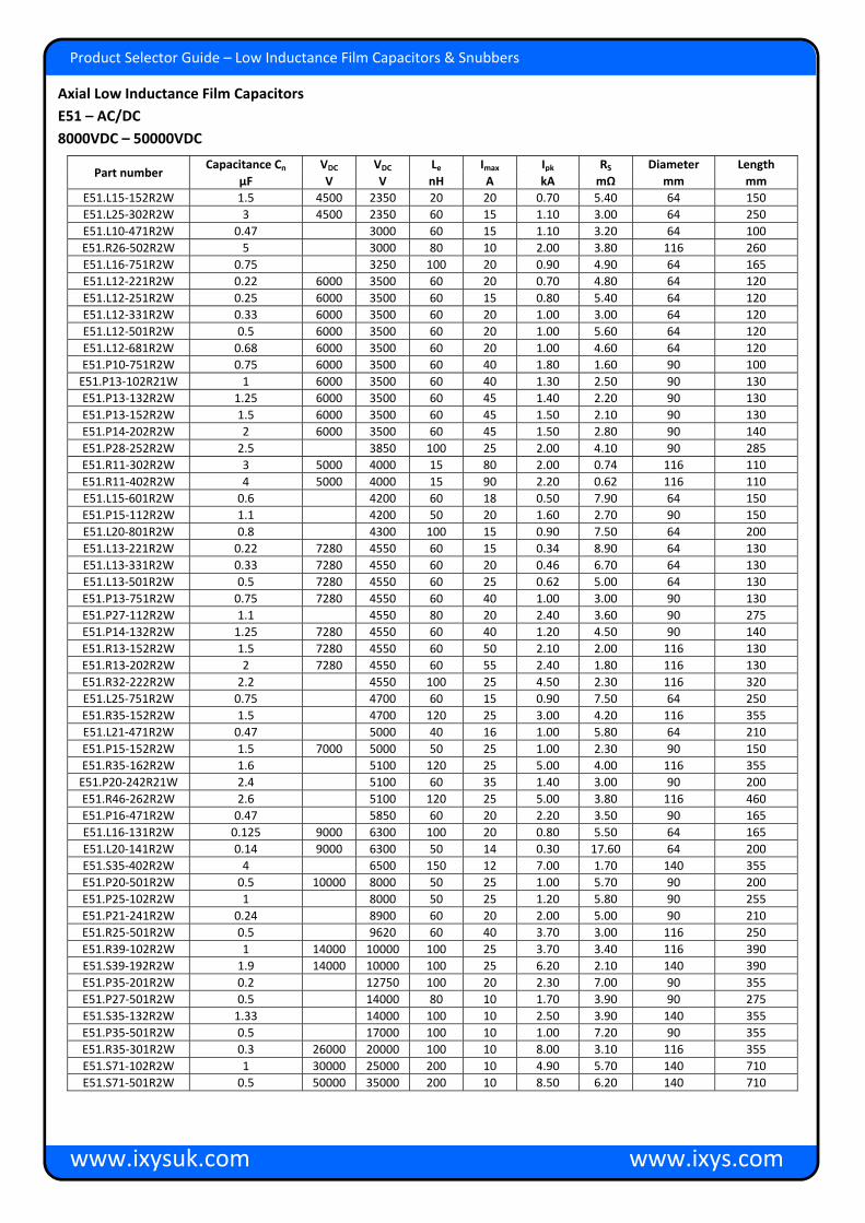
Axial Low Inductance Film Capacitors E51 – AC/DC 8000VDC – 50000VDC
Part number Capacitance Cn VDC VDC Le Imax Ipk RS Diameter Length
µF V V nH A kA mΩ mm mm E51.L15‐152R2W 1.5 4500 2350 20 20 0.70 5.40 64 150 E51.L25‐302R2W 3 4500 2350 60 15 1.10 3.00 64 250 E51.L10‐471R2W 0.47 3000 60 15 1.10 3.20 64 100 E51.R26‐502R2W 5 3000 80 10 2.00 3.80 116 260 E51.L16‐751R2W 0.75 3250 100 20 0.90 4.90 64 165 E51.L12‐221R2W 0.22 6000 3500 60 20 0.70 4.80 64 120 E51.L12‐251R2W 0.25 6000 3500 60 15 0.80 5.40 64 120 E51.L12‐331R2W 0.33 6000 3500 60 20 1.00 3.00 64 120 E51.L12‐501R2W 0.5 6000 3500 60 20 1.00 5.60 64 120 E51.L12‐681R2W 0.68 6000 3500 60 20 1.00 4.60 64 120 E51.P10‐751R2W 0.75 6000 3500 60 40 1.80 1.60 90 100 E51.P13‐102R21W 1 6000 3500 60 40 1.30 2.50 90 130 E51.P13‐132R2W 1.25 6000 3500 60 45 1.40 2.20 90 130 E51.P13‐152R2W 1.5 6000 3500 60 45 1.50 2.10 90 130 E51.P14‐202R2W 2 6000 3500 60 45 1.50 2.80 90 140 E51.P28‐252R2W 2.5 3850 100 25 2.00 4.10 90 285 E51.R11‐302R2W 3 5000 4000 15 80 2.00 0.74 116 110 E51.R11‐402R2W 4 5000 4000 15 90 2.20 0.62 116 110 E51.L15‐601R2W 0.6 4200 60 18 0.50 7.90 64 150 E51.P15‐112R2W 1.1 4200 50 20 1.60 2.70 90 150 E51.L20‐801R2W 0.8 4300 100 15 0.90 7.50 64 200 E51.L13‐221R2W 0.22 7280 4550 60 15 0.34 8.90 64 130 E51.L13‐331R2W 0.33 7280 4550 60 20 0.46 6.70 64 130 E51.L13‐501R2W 0.5 7280 4550 60 25 0.62 5.00 64 130 E51.P13‐751R2W 0.75 7280 4550 60 40 1.00 3.00 90 130 E51.P27‐112R2W 1.1 4550 80 20 2.40 3.60 90 275 E51.P14‐132R2W 1.25 7280 4550 60 40 1.20 4.50 90 140 E51.R13‐152R2W 1.5 7280 4550 60 50 2.10 2.00 116 130 E51.R13‐202R2W 2 7280 4550 60 55 2.40 1.80 116 130 E51.R32‐222R2W 2.2 4550 100 25 4.50 2.30 116 320 E51.L25‐751R2W 0.75 4700 60 15 0.90 7.50 64 250 E51.R35‐152R2W 1.5 4700 120 25 3.00 4.20 116 355 E51.L21‐471R2W 0.47 5000 40 16 1.00 5.80 64 210 E51.P15‐152R2W 1.5 7000 5000 50 25 1.00 2.30 90 150 E51.R35‐162R2W 1.6 5100 120 25 5.00 4.00 116 355 E51.P20‐242R21W 2.4 5100 60 35 1.40 3.00 90 200 E51.R46‐262R2W 2.6 5100 120 25 5.00 3.80 116 460 E51.P16‐471R2W 0.47 5850 60 20 2.20 3.50 90 165 E51.L16‐131R2W 0.125 9000 6300 100 20 0.80 5.50 64 165 E51.L20‐141R2W 0.14 9000 6300 50 14 0.30 17.60 64 200 E51.S35‐402R2W 4 6500 150 12 7.00 1.70 140 355 E51.P20‐501R2W 0.5 10000 8000 50 25 1.00 5.70 90 200 E51.P25‐102R2W 1 8000 50 25 1.20 5.80 90 255 E51.P21‐241R2W 0.24 8900 60 20 2.00 5.00 90 210 E51.R25‐501R2W 0.5 9620 60 40 3.70 3.00 116 250 E51.R39‐102R2W 1 14000 10000 100 25 3.70 3.40 116 390 E51.S39‐192R2W 1.9 14000 10000 100 25 6.20 2.10 140 390 E51.P35‐201R2W 0.2 12750 100 20 2.30 7.00 90 355 E51.P27‐501R2W 0.5 14000 80 10 1.70 3.90 90 275 E51.S35‐132R2W 1.33 14000 100 10 2.50 3.90 140 355 E51.P35‐501R2W 0.5 17000 100 10 1.00 7.20 90 355 E51.R35‐301R2W 0.3 26000 20000 100 10 8.00 3.10 116 355 E51.S71‐102R2W 1 30000 25000 200 10 4.90 5.70 140 710 E51.S71‐501R2W 0.5 50000 35000 200 10 8.50 6.20 140 710

www.ixysuk.com www.ixys.com
Product Selector Guide – Low Inductance Film Capacitors & Snubbers
Can and termination details
Capacitors with can diameter 90, 116 and 140mm
Can Material: Plastic can filled with solid PU resin
Terminals: Axial thread. M8×12mm
IMAX: @ terminals = 100A
Protection: IP00
Humidity class: F

www.ixysuk.com www.ixys.com
Product Selector Guide – Low Inductance Film Capacitors & Snubbers
Axial Low Inductance Film Capacitors E53 – AC/DC 280VAC – 2450VAC/550VDC – 7200VDC
Standards: IEC 61071, optional IEC61881
Can: Plastic (UL94:V0)
Mounting position: Optional
Filling material: Solid, based on vegetable oil, non‐PCB
Internal protection: None
Fire load: 40MJ/kg
Cn tolerance: ±10% (5% optional)
Self‐inductance: C. 15nH
Insulation strength C×Ris: 5000s
tanδ0: 2×10‐4
Limit temperatures:
Θmin – Θmax: ‐25°C ‐ +85°C
Θmax (HOTSPOT) ø67‐85: ≤+85°C
Storage Temperature: ‐40°C ‐ +85°C
Failure rate: 100 FIT Reference interval – 100000hrs, Θ (HOTSPOT) ≤70°C
Part number Capacitance Cn VDC VAC VRMS Imax Ipk RS Diameter Length
µF V V V A kA mΩ mm mm E53.H59‐503T1W 50 550 280 200 60 0.83 0.80 55 59 E53.M59‐104T2W 100 550 280 200 80 1.70 0.40 75 59 E53.P59‐204T2W 200 550 280 200 80 3.30 0.20 95 59 E53.Q59‐254T2W 250 550 280 200 80 3.30 0.15 105 59 E53.H59‐333T1W 33 700 350 250 55 0.68 0.95 55 59 E53.M59‐683T2W 68 700 350 250 80 1.40 0.50 75 59 E53.P59‐124T2W 120 700 350 250 80 2.50 0.30 95 59 E53.Q59‐154T2W 150 700 350 250 100 3.10 0.25 105 59 E53.R60‐204T2W 200 700 350 250 100 3.10 0.20 115 60 E53.R11‐314T2W 310 700 350 250 100 3.00 0.30 115 110 E53.H59‐303T1W 30 900 350 250 60 0.68 0.85 55 59 E53.M59‐603T2W 60 900 350 250 80 1.40 0.50 75 59 E53.P59‐104T2W 100 900 350 250 80 2.30 0.35 95 59 E53.Q59‐124T2W 120 900 350 250 100 2.80 0.20 105 59 E53.R60‐144T2W 140 900 350 250 100 3.10 0.20 115 60 E53.R11‐274T2W 265 900 350 250 100 3.00 0.35 115 110
Axial Low Inductance Film Capacitors E53 – AC/DC 280VAC – 350VAC/550VDC – 900VDC

www.ixysuk.com www.ixys.com
Product Selector Guide – Low Inductance Film Capacitors & Snubbers
Axial Low Inductance Film Capacitors E53 – AC/DC 350VAC – 700VAC/1100VDC – 1700VDC
Axial Low Inductance Film Capacitors E53 – AC/DC 700VAC/2000VDC – 2250VDC
Part number Capacitance Cn VDC VAC VRMS Imax Ipk RS Diameter Length
µF V V V A kA mΩ mm mm E53.H59‐123T1W 12 1100 350 250 40 0.40 1.70 55 59 E53.H59‐153T1W 15 1100 350 250 40 0.50 1.10 55 59 E53.M59‐253T2W 25 1100 350 250 70 0.83 0.71 75 59 E53.P59‐503T2W 50 1100 350 250 80 1.70 0.34 95 59 E53.Q59‐603T2W 60 1100 350 250 100 2.00 0.35 105 59 E53.R60‐803T2W 80 1100 350 250 100 3.00 0.21 115 60 E53.R11‐184T2W 175 1100 350 250 100 2.60 0.41 115 110 E53.H59‐802T1W 8 1400 350 250 38 0.33 2.00 55 59 E53.M59‐163T2W 16 1400 350 250 60 0.66 1.00 75 59 E53.P59‐303T2W 30 1400 350 250 80 1.20 0.55 95 59 E53.R60‐503T2W 50 1400 350 250 100 2.20 0.30 115 60 E53.R11‐114T2W 110 1400 350 250 100 2.00 0.52 115 110 E53.H59‐472T1W 4.7 1700 700 500 45 0.50 1.30 55 59 E53.M59‐103T2W 10 1700 700 500 80 1.10 0.60 75 59 E53.P59‐163T2W 16 1700 700 500 80 1.80 0.37 95 59 E53.Q59‐223T2W 22 1700 700 500 100 2.50 0.27 105 59 E53.R60‐333T2W 33 1700 700 500 100 3.50 0.20 115 60 E53.R11‐683T2W 68 1700 700 500 100 3.10 0.35 115 110
Part number Capacitance Cn VDC VAC VRMS Imax Ipk RS Diameter Length
µF V V V A kA mΩ mm mm E53.H59‐332T1W 3.3 2000 700 500 40 0.42 1.60 55 59 E53.M59‐802T2W 8 2000 700 500 80 1.00 0.65 75 59 E53.P59‐143T2W 14 2000 700 500 80 1.80 0.35 95 59 E53.Q59‐183T2W 18 2000 700 500 100 2.30 0.30 105 59 E53.R60‐243T2W 24 2000 700 500 100 3.00 0.20 115 60 E53.R11‐533T2W 52.2 2000 700 500 100 2.80 0.39 115 110 E53.H59‐252T1W 2.5 2250 700 500 40 0.37 1.80 55 59 E53.M59‐602T2W 6 2250 700 500 70 0.88 0.76 75 59 E53.P59‐103T2W 10 2250 700 500 80 1.50 0.46 95 59 E53.Q59‐123T2W 12 2250 700 500 100 2.50 0.37 105 59 E53.Q59‐143T2W 14 2250 700 500 100 2.00 0.33 105 59 E53.Q59‐153T2W 15 2250 700 500 100 2.10 0.27 105 59 E53.R60‐183T2W 18 2250 700 500 100 2.60 0.25 115 60 E53.R11‐403T2W 40 2250 700 500 100 2.40 0.45 115 110

www.ixysuk.com www.ixys.com
Product Selector Guide – Low Inductance Film Capacitors & Snubbers
Axial Low Inductance Film Capacitors E53 – AC/DC 700VAC – 1050VAC/2800VDC – 3200VDC
Axial Low Inductance Film Capacitors E53 – AC/DC 1400VAC –2450VAC/2450VDC – 7200VDC
Part number Capacitance Cn VDC VAC VRMS Imax Ipk RS Diameter Length
µF V V V A kA mΩ mm mm E53.H59‐152T1W 1.5 2800 700 500 32 0.27 2.40 55 59 E53.M59‐332T2W 3.3 2800 700 500 60 0.60 1.10 75 59 E53.P59‐502T2W 5 2800 700 500 80 2.00 0.42 95 59 E53.P59‐682T2W 6.8 2800 700 500 80 1.20 0.55 95 59 E53.P59‐752T2W 7.5 2800 700 500 80 1.50 0.50 95 59 E53.Q59‐802T2W 8 2800 700 500 100 1.50 0.45 105 59 E53.Q59‐103T2W 10 2800 700 500 100 1.50 0.40 105 59 E53.R60‐123T2W 12 2800 700 500 100 2.20 0.30 115 60 E53.R11‐253T2W 25 2800 700 500 100 1.90 0.57 115 110 E53.H59‐102T1W 1 3200 1050 750 40 0.35 1.60 55 59 E53.M59‐252T2W 2.5 3200 1050 750 75 0.90 0.65 75 59 E53.P59‐302T2W 3 3200 1050 750 80 1.20 0.54 95 59 E53.P59‐402T2W 4 3200 1050 750 80 1.50 0.40 95 59 E53.Q59‐452T2W 4.5 3200 1050 750 100 1.60 0.40 105 59 E53.Q59‐502T2W 5 3200 1050 750 100 1.80 0.32 105 59 E53.Q59‐602T2W 6 3200 1050 750 100 2.20 0.28 105 59 E53.R60‐702T2W 7 3200 1050 750 100 3.0 0.25 115 60
Part number Capacitance Cn VDC VAC VRMS Imax Ipk RS Diameter Length
µF V V V A kA mΩ mm mm E53.H59‐122T1W 1.16 2450 1400 1000 20 0.70 1.20 55 59 E53.M59‐242T2W 2.4 2450 1400 1000 60 1.50 0.56 75 59 E53.Q59‐522T2W 5.2 2450 1400 1000 100 3.00 0.26 105 59 E53.R60‐642T2W 6.4 2450 1400 1000 100 4.00 0.21 115 60 E53.R11‐802T2W 8 3600 1400 1000 100 2.30 0.52 115 110 E53.R11‐103T2W 10 3600 1400 1000 100 2.50 0.94 115 110 E53.H59‐471T1W 0.47 3750 2100 1500 20 0.70 2.90 55 59 E53.M59‐112T2W 1.1 3750 2100 1500 60 1.60 1.20 75 59 E53.P59‐172T2W 1.7 3750 2100 1500 80 2.50 0.80 95 59 E53.Q59‐222T2W 2.15 3750 2100 1500 100 3.00 0.64 105 59 E53.R60‐272T2W 2.7 3750 2100 1500 100 4.00 0.51 115 60 E53.R11‐302T21W 3 5000 2100 1500 125 2.10 1.20 115 110 E53.R11‐402T21W 4 5000 2100 1500 125 2.50 1.00 115 110 E53.H97‐221T1W 0.22 5600 2450 1750 25 0.20 13.70 55 97 E53.H97‐251T1W 0.25 5600 2450 1750 25 0.30 12.10 55 97 E53.H97‐501T1W 0.5 5600 2450 1750 25 0.40 8.00 55 97 E53.H97‐221T11W 0.22 7200 2450 1750 25 0.20 13.70 55 97 E53.H97‐251T1W 0.25 7200 2450 1750 25 0.30 12.10 55 97

www.ixysuk.com www.ixys.com
Product Brief – Title
Product Selector Guide – Low Inductance Film Capacitors & Snubbers
Axial Low Inductance Film Capacitors E53 – DC 500VDC – 5000VDC
Standards: IEC 61071, optional IEC61881
Can: Plastic (UL94:V0)
Mounting position: Optional
Filling material: Solid, based on vegetable oil, non‐PCB
Internal protection: None
Fire load: 40MJ/kg
Cn tolerance: ±10% (5% optional)
Insulation strength C×Ris: 5000s
tanδ0: 2×10‐4
Limit temperatures:
Θmin – Θmax: ‐25°C ‐ +85°C
Θmax (HOTSPOT) ø67‐85: ≤+85°C
Storage Temperature: ‐40°C ‐ +85°C
Failure rate: 50 FIT Reference interval – 100000hrs, Θ (HOTSPOT) ≤70°C
Part number Capacitance Cn VDC Le Imax Ipk RS Diameter Length
µF V nH A kA mΩ mm mm E53.N51‐204H1W 200 500 30 60 3.30 0.75 85 51 E53.N68‐284H1W 280 500 35 60 3.50 0.84 85 68 E53.N76‐404H1W 400 500 40 60 3.30 1.10 85 76 E53.N51‐154H1W 150 600 30 60 2.90 0.80 85 51 E53.N68‐204H1W 200 600 35 60 2.90 0.92 85 68 E53.N76‐304H1W 300 600 40 60 2.90 1.20 85 76 E53.N51‐124H1W 120 800 30 60 2.60 0.84 85 51 E53.N68‐154H1W 150 800 35 60 2.50 1.00 85 68 E53.N76‐244H1W 240 800 40 60 2.60 1.30 85 76 E55.Q59‐254T2W 250 800 15 100 8.30 0.35 105 59 E53.N51‐753H1W 75 1000 30 60 2.00 1.00 85 51 E53.N68‐104H1W 100 1000 35 60 2.00 1.20 85 68 E53.N76‐154H1W 150 1000 40 75 2.00 1.50 85 76 E53.N51‐503H1W 50 1200 30 70 1.60 1.10 85 51 E55.M59‐503T2W 50 1200 15 65 2.40 0.98 75 59 E53.M59‐503T2W 50 1200 35 70 1.70 1.30 75 59 E53.N68‐683H1W 68 1200 15 80 4.30 0.55 85 68 E55.P59‐903T2W 90 1200 40 60 1.60 1.80 95 59 E53.N51‐383H1W 37.5 1400 30 60 1.40 1.20 85 51 E53.N68‐503H1W 50 1400 35 60 1.40 1.50 85 68 E53.N76‐753H1W 75 1400 40 60 1.40 2.00 85 76 E53.N51‐303H1W 30 1600 30 60 1.30 1.30 85 51 E53.N68‐403H1W 40 1600 35 60 1.30 1.60 85 68 E53.N76‐603H1W 60 1600 40 50 1.30 2.10 85 76 E55.M59‐223T2W 22 1800 15 40 1.60 1.50 75 59 E53.N68‐223H1W 22 2000 35 55 0.95 1.60 85 68 E55.R60‐103T2W 10 3200 15 100 2.80 0.71 115 60 E55.R11‐103T2W 10 5000 15 100 1.90 1.30 115 110

Product Brief – Title
www.ixysuk.com www.ixys.com
Product Selector Guide – Low Inductance Film Capacitors & Snubbers
Can and termination details
T1 Capacitors with can diameter 55‐60mm
T2 Capacitors with can diameter 75‐115mm
Can Material: Plastic can filled with solid PU resin
Terminals: Axial thread.
T1 = M6×10mm
T2 = M8×10mm
IMAX: @ terminals
T1 = 60A
T2 = 100A
Protection: IP00
Humidity class: G
H1 Capacitors with can diameter 85mm
Can Material: Plastic can filled with solid PU resin
Fixing: Lateral mounting brackets
Terminals: Threaded studs M8×20mm
IMAX: @ terminals = 100A
Protection: IP00
Humidity class: F

IXYS UK Westcode Ltd’s BS EN ISO9001 quality system is registered by BSI
Langley Park Way Chippenham, SN15 1GE United Kingdom Tel: +44 (0)1249 444524 Fax: +44 (0)1249 659448 E‐mail: [email protected]
Edisonstr. 15 D‐68623 Lampertheim Germany Tel: +49 (0) 6206 503‐0 Fax: +44 (0) 6206 503627 E‐mail: [email protected]
We are supported by a global network of local offices, representatives and distributors. Please visit our website for more information
www.ixysuk.com www.ixys.com
Product Selector Guide – Low Inductance Film Capacitors & Snubbers
Important information
Safety IXYS UK will not be responsible for any kind of damages to persons or property due to improper application of any capacitors purchased from IXYS UK or its distributors. The capacitors should only be used for the application intended. Mind that electrical or mechanical misapplication of capacitors can become hazardous. Misapplied capacitors can catch fire or explode and cause bodily injury or property damage due to the expulsion of material or metal fragments. Please consult the detailed instructions for mounting and application in our brochure “application notes for power capacitors”. For more information please contact IXYS UK Mounting and cooling The useful life of a capacitor may be reduced dramatically if exposed to excessive heat. Typically, an increase in ambient temperature of 7°C will halve the expected life of the capacitor. Please ensure capacitors are used within the stated operating temperatures. To avoid overheating, the capacitors must be allowed to cool unhindered and should be shielded from external heat sources. IXYS UK recommends forced ventilation for all applications with detuning reactors. Give at least 20mm clearance between the capacitors for natural or forced ventilation and do not place them directly above or next to heat sources such as tuning or detuning reactors, bus bars etc. Protection against over‐voltages and short circuits – Self‐healing dielectric All dielectric structures used in IXYS UK power capacitors are ‘self‐healing’; in the event of a voltage breakdown the metal layers around the breakdown channel are evaporated by the temperature of the electric arc that forms between the electrodes. They are removed within a few microseconds and pushed apart by the pressure generated in the centre of the breakdown spot. An insulation area is formed which is reliably resistive and voltage proof for all operation requirements of the capacitor. The capacitor remains fully functional during and after the breakdown. For voltages within the permitted testing and operating limits of the capacitors are short circuit and overvoltage proof. They are also protected against external short circuits as far as the resulting surge discharges do not exceed the specified surge current limits.