Embed Size (px)
Citation preview
March 2015
MEIC Collaboration Meeting
30 – 31 March 2015
Low Energy RHIC electron Cooling
(LEReC)
Alexei Fedotov
LEReC overview: project goal and cooling approach
March 2015
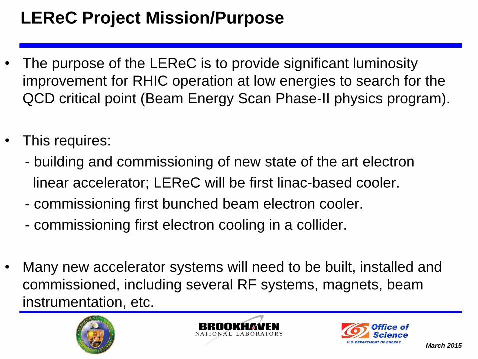
• The purpose of the LEReC is to provide significant luminosity
improvement for RHIC operation at low energies to search for the
QCD critical point (Beam Energy Scan Phase-II physics program).
• This requires:
- building and commissioning of new state of the art electron
linear accelerator; LEReC will be first linac-based cooler.
- commissioning first bunched beam electron cooler.
- commissioning first electron cooling in a collider.
• Many new accelerator systems will need to be built, installed and
commissioned, including several RF systems, magnets, beam
instrumentation, etc.
LEReC Project Mission/Purpose
March 2015 3
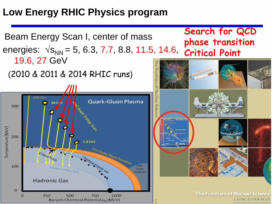
Search for QCD phase transition Critical Point
Beam Energy Scan I, center of mass
energies: sNN = 5, 6.3, 7.7, 8.8, 11.5, 14.6,
19.6, 27 GeV
(2010 & 2011 & 2014 RHIC runs)
Low Energy RHIC Physics program
March 2015
4
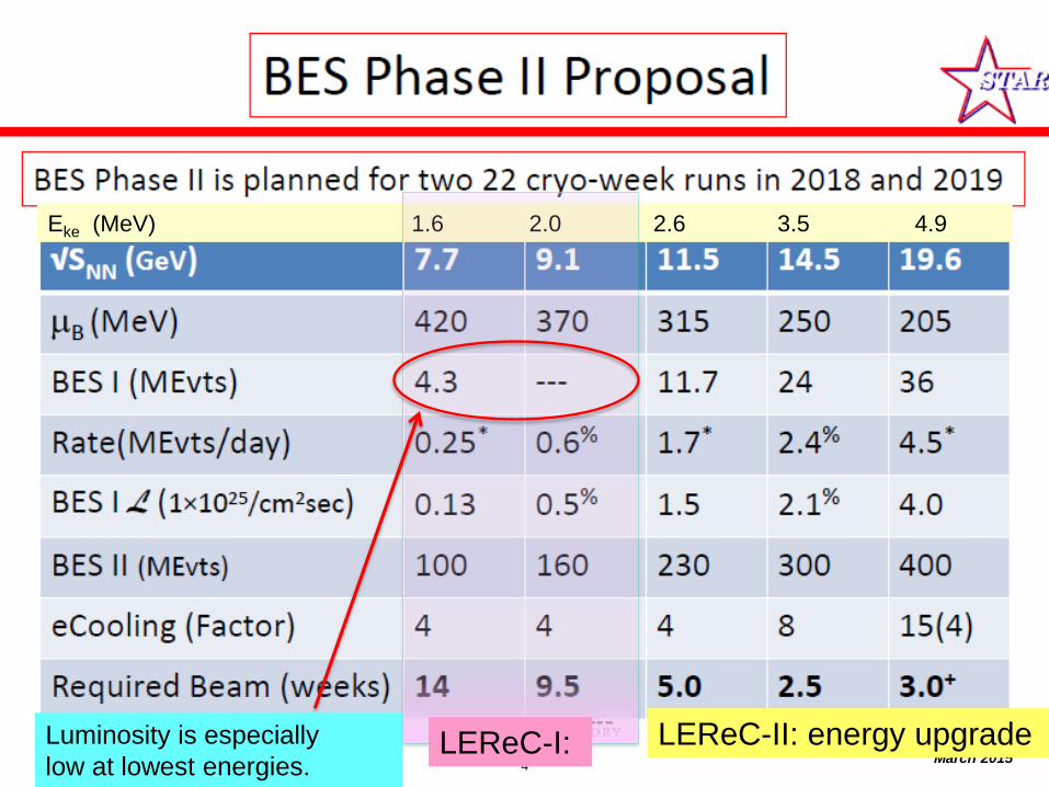
Eke (MeV) 1.6 2.0 2.6 3.5 4.9
Luminosity is especially
low at lowest energies. LEReC-I: LEReC-II: energy upgrade
March 2015 5
Low-energy RHIC operation
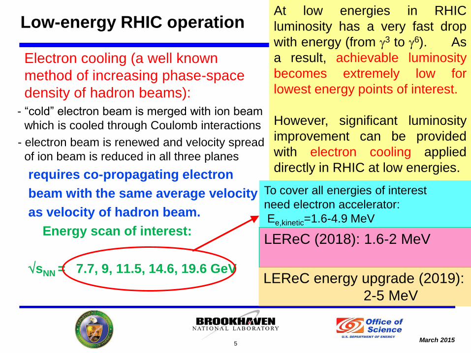
Electron cooling (a well known
method of increasing phase-space
density of hadron beams):
- “cold” electron beam is merged with ion beam
which is cooled through Coulomb interactions
- electron beam is renewed and velocity spread
of ion beam is reduced in all three planes
requires co-propagating electron
beam with the same average velocity
as velocity of hadron beam.
Energy scan of interest:
sNN = 7.7, 9, 11.5, 14.6, 19.6 GeV
To cover all energies of interest
need electron accelerator:
Ee,kinetic=1.6-4.9 MeV
At low energies in RHIC
luminosity has a very fast drop
with energy (from g3 to g6). As
a result, achievable luminosity
becomes extremely low for
lowest energy points of interest.
However, significant luminosity
improvement can be provided
with electron cooling applied
directly in RHIC at low energies.
LEReC (2018): 1.6-2 MeV
LEReC energy upgrade (2019):
2-5 MeV
March 2015 6
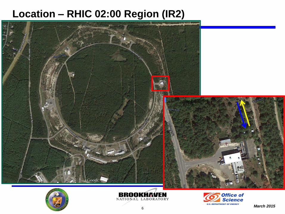
Location – RHIC 02:00 Region (IR2)
March 2015
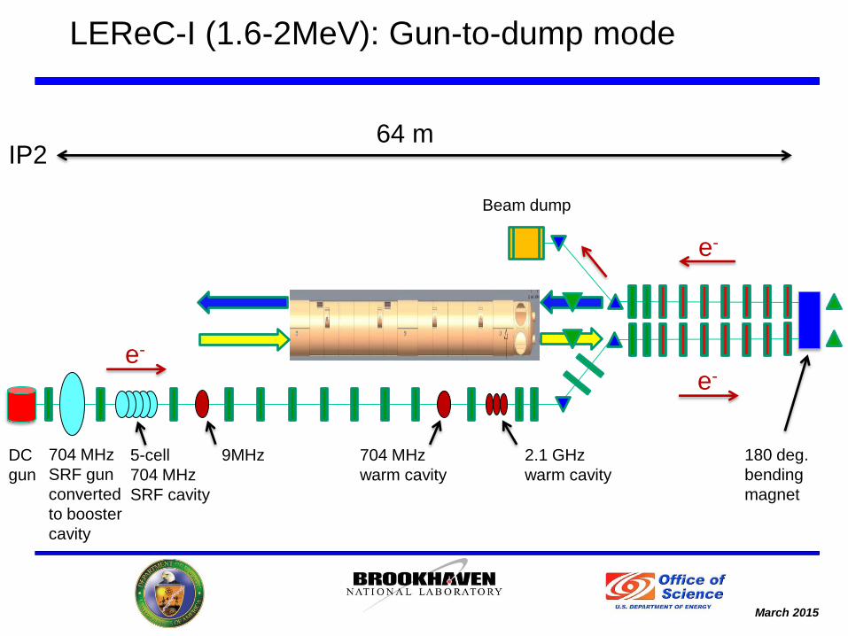
LEReC-I (1.6-2MeV): Gun-to-dump mode
704 MHz
SRF gun
converted
to booster
cavity
5-cell
704 MHz
SRF cavity
9MHz 704 MHz
warm cavity
2.1 GHz
warm cavity
Beam dump
180 deg.
bending
magnet
e-
e-
IP2 64 m
e-
DC
gun
March 2015
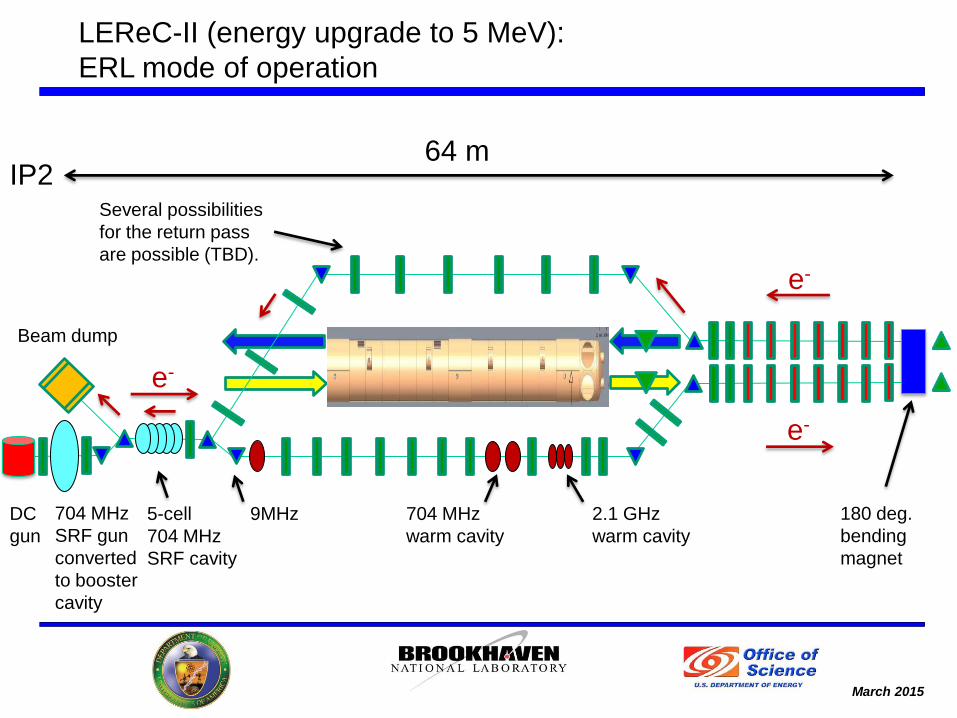
LEReC-II (energy upgrade to 5 MeV):
ERL mode of operation
5-cell
704 MHz
SRF cavity
9MHz 704 MHz
warm cavity
2.1 GHz
warm cavity
Beam dump
180 deg.
bending
magnet
e-
e-
IP2 64 m
e-
704 MHz
SRF gun
converted
to booster
cavity
DC
gun
Several possibilities
for the return pass
are possible (TBD).
March 2015 9
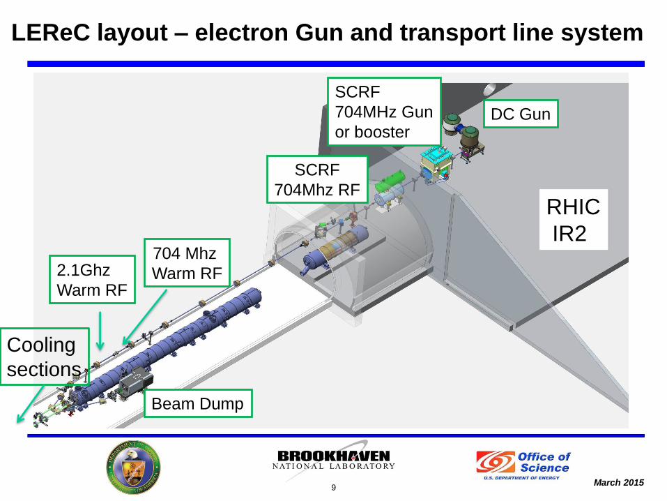
SCRF
704MHz Gun
or booster
2.1Ghz
Warm RF
Beam Dump
SCRF
704Mhz RF
LEReC layout – electron Gun and transport line system
704 Mhz
Warm RF
DC Gun
Cooling
sections
RHIC
IR2
March 2015
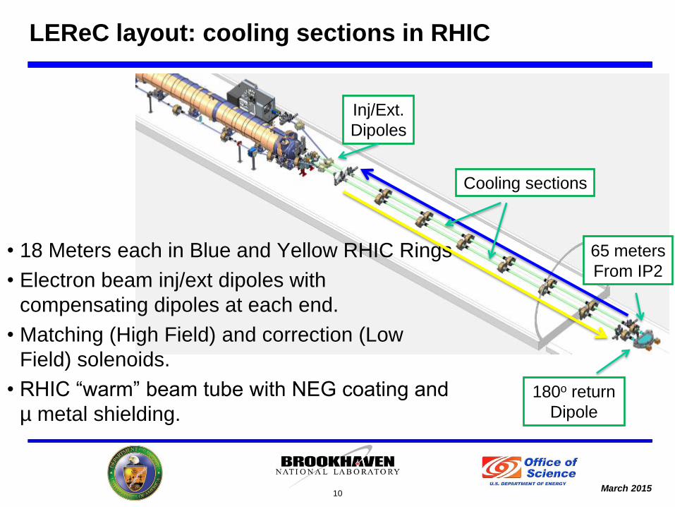
• 18 Meters each in Blue and Yellow RHIC Rings
• Electron beam inj/ext dipoles with
compensating dipoles at each end.
• Matching (High Field) and correction (Low
Field) solenoids.
• RHIC “warm” beam tube with NEG coating and
µ metal shielding.
10
LEReC layout: cooling sections in RHIC
180o return
Dipole
Inj/Ext.
Dipoles
Cooling sections
65 meters
From IP2
March 2015
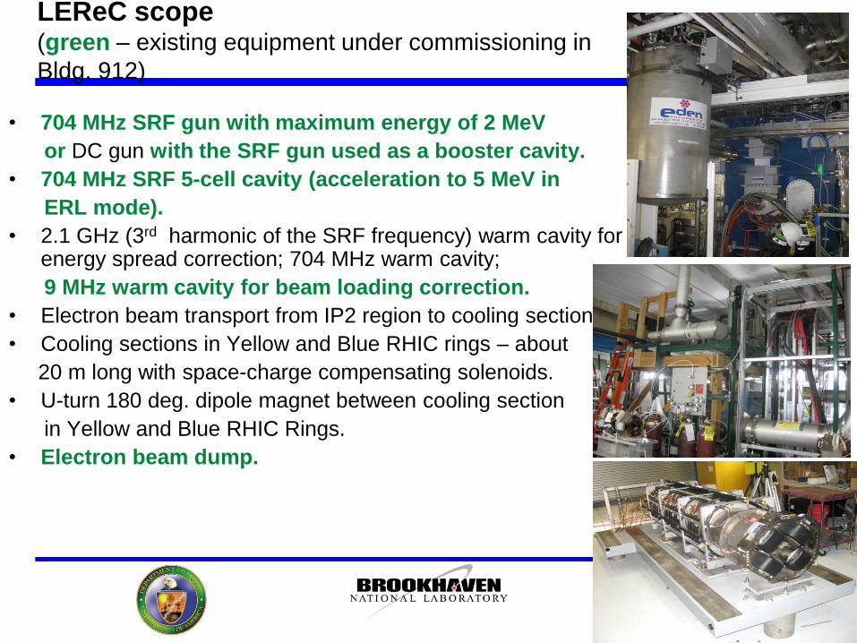
LEReC scope (green – existing equipment under commissioning in
Bldg. 912)
• 704 MHz SRF gun with maximum energy of 2 MeV
or DC gun with the SRF gun used as a booster cavity.
• 704 MHz SRF 5-cell cavity (acceleration to 5 MeV in
ERL mode).
• 2.1 GHz (3rd harmonic of the SRF frequency) warm cavity for energy spread correction; 704 MHz warm cavity;
9 MHz warm cavity for beam loading correction.
• Electron beam transport from IP2 region to cooling sections
• Cooling sections in Yellow and Blue RHIC rings – about
20 m long with space-charge compensating solenoids.
• U-turn 180 deg. dipole magnet between cooling section
in Yellow and Blue RHIC Rings.
• Electron beam dump.
11
March 2015
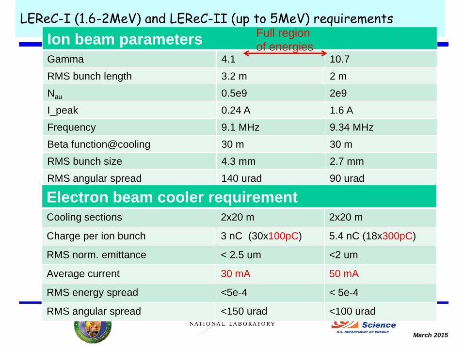
LEReC-I (1.6-2MeV) and LEReC-II (up to 5MeV) requirements
Ion beam parameters
Gamma 4.1 10.7
RMS bunch length 3.2 m 2 m
Nau 0.5e9 2e9
I_peak 0.24 A 1.6 A
Frequency 9.1 MHz 9.34 MHz
Beta function@cooling 30 m 30 m
RMS bunch size 4.3 mm 2.7 mm
RMS angular spread 140 urad 90 urad
Electron beam cooler requirement
Cooling sections 2x20 m 2x20 m
Charge per ion bunch 3 nC (30x100pC) 5.4 nC (18x300pC)
RMS norm. emittance < 2.5 um <2 um
Average current 30 mA 50 mA
RMS energy spread <5e-4 < 5e-4
RMS angular spread <150 urad <100 urad
Full region
of energies
March 2015
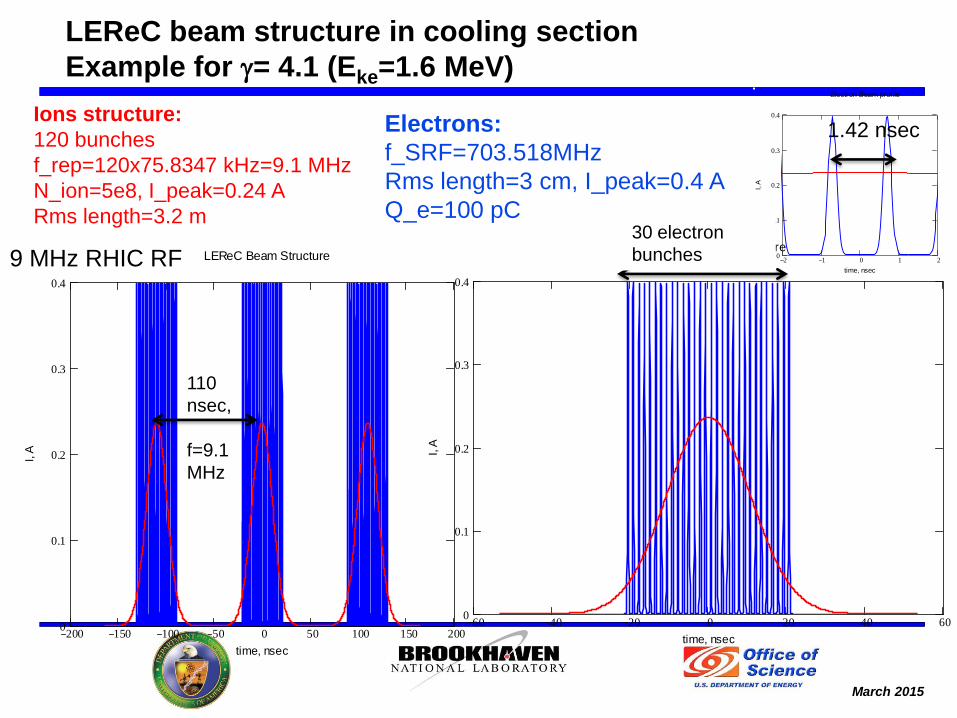
LEReC beam structure in cooling section
Example for g= 4.1 (Eke=1.6 MeV)
LEReC Beam Structure
200 150 100 50 0 50 100 150 2000
0.1
0.2
0.3
0.4
time, nsec
I, A
LEReC Beam Structure
60 40 20 0 20 40 600
0.1
0.2
0.3
0.4
time, nsec
I, A
Electron Beam profile
2 1 0 1 20
0.1
0.2
0.3
0.4
time, nsec
I, A
110
nsec,
f=9.1
MHz
Ions structure:
120 bunches
f_rep=120x75.8347 kHz=9.1 MHz
N_ion=5e8, I_peak=0.24 A
Rms length=3.2 m
1.42 nsec
30 electron
bunches
Electrons:
f_SRF=703.518MHz
Rms length=3 cm, I_peak=0.4 A
Q_e=100 pC
9 MHz RHIC RF
March 2015
• Although electron cooling has been applied in numerous machines, this
is by far the most ambitious application to date and must demonstrate
several innovations.
• The critical path for the overall facility commissioning is the availability of
a tested and functional electron source.
Some summary points from MAC review
(December 8-10, 2014) report on LEReC
March 2015
LEReC electron source status and plans
• 2015: Continue SRF gun beam tests in Bldg. 912 with new
cathode stalk, new 704 MHz LEReC laser system towards CW
operation with high-current is under development (goal is to
demonstrate 300 pC bunch charges and average currents up to
50 mA needed for LEReC by early 2016).
• November 2014: Collaboration and work on contract with
Cornell on DC gun started. Goal is to have operational DC gun
by mid 2016.
15
March 2015
704 MHz SRF gun progress
1. Aug. to Oct. 2013: Commissioned SRF gun cavity with copper cathode stalk
inserted.
Found operational parameters: 1.85 MV, 180 ms, 1 Hz - limited by
multipacting in the stalk.
Design a new multipacting-free cathode stalk with Ta tip for high QE => high
current electron beam.
2. May 28 to Jun. 18, 2014: Commissioning with Cs3Sb photocathode
Commissioned all subsystems and demonstrated system integration;
dark current was observed.
3. Nov. 17, 2014 to present: First photoemission beam commissioning
Observed photoemission beam: 8pC bunch charge/1 mA average current
4. March 2015:
new cathode stalk with Ta tip commissioned;
beam studies are coming.
16
March 2015
LEReC DC gun requirements
Operating voltage: 400-500 kV, Cornell University (CU)
Charge per bunch (LEReC Phase-1, 2017-18): 100 pC (CU)
Average current (LEReC Phase-1, 2017-18): 30 mA (CU)
Charge per bunch (LEReC Phase-II, 2018-19): 300 pC (CU)
Average current (LEReC Phase-II, 2018-19): 50mA
Needed beam quality:
Rms normalized emittance < 2 mm for charges up to 300pC (from the
gun) – demonstrated by CU
RMS energy spread <2e-4 ( from gun/ripple contribution)
- Stable 24/7 operation
-Cathodes exchanging mechanism for quick cathode replacement
without significant delay on operation.
17
March 2015
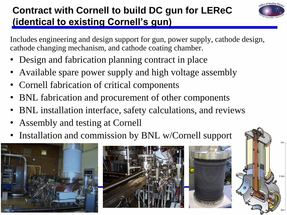
Includes engineering and design support for gun, power supply, cathode design, cathode changing mechanism, and cathode coating chamber.
• Design and fabrication planning contract in place
• Available spare power supply and high voltage assembly
• Cornell fabrication of critical components
• BNL fabrication and procurement of other components
• BNL installation interface, safety calculations, and reviews
• Assembly and testing at Cornell
• Installation and commission by BNL w/Cornell support
Contract with Cornell to build DC gun for LEReC
(identical to existing Cornell’s gun)
March 2015
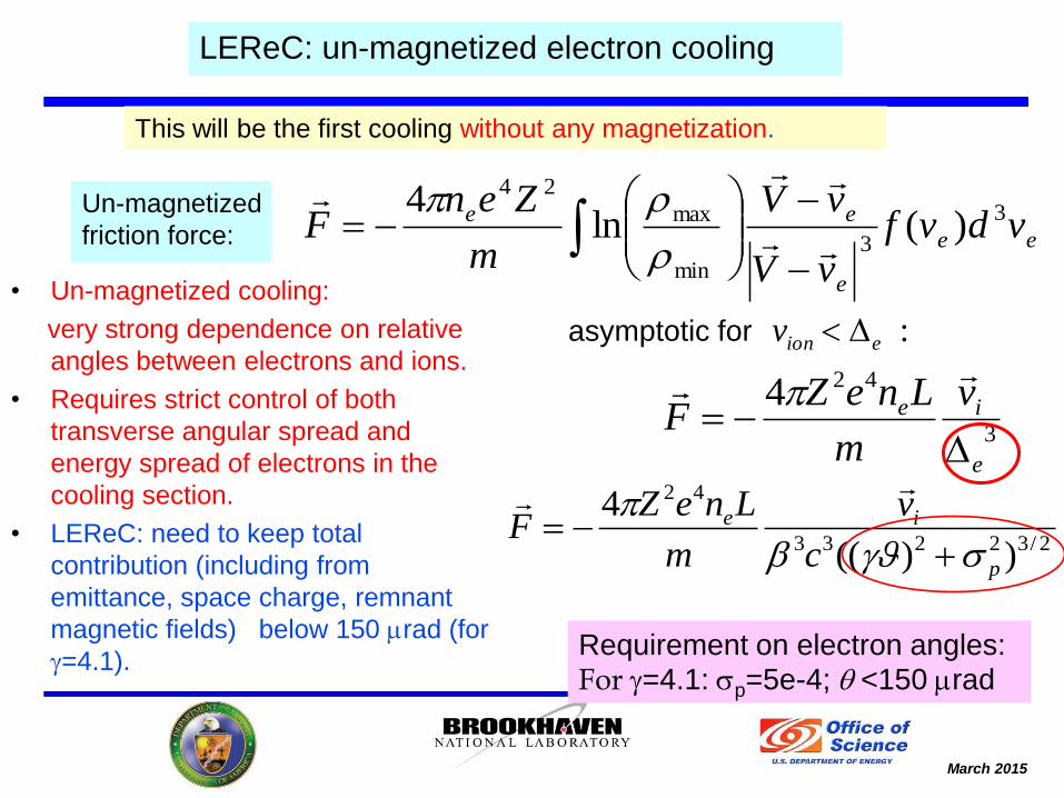
• Un-magnetized cooling:
very strong dependence on relative
angles between electrons and ions.
• Requires strict control of both
transverse angular spread and
energy spread of electrons in the
cooling section.
• LEReC: need to keep total
contribution (including from
emittance, space charge, remnant
magnetic fields) below 150 mrad (for
g=4.1).
LEReC: un-magnetized electron cooling
2/32233
42
))((
4
p
ie
c
v
m
LneZF
g
Requirement on electron angles: For g=4.1: p=5e-4; q <150 mrad
ee
e
ee vdvfvV
vV
m
ZenF 3
3
min
max
24
)(ln4
This will be the first cooling without any magnetization.
3
424
e
ie v
m
LneZF
:eionv asymptotic for
Un-magnetized
friction force:
March 2015
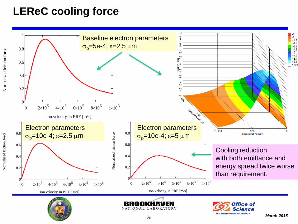
LEReC cooling force
20
0 2 105
4 105
6 105
8 105
1 106
0
0.2
0.4
0.6
0.8
1
ion velocity in PRF [m/s]
Norm
aliz
ed f
rict
ion
forc
e
0 2 105
4 105
6 105
8 105
1 106
0
0.2
0.4
0.6
0.8
1
ion velocity in PRF {m/s]
No
rmal
ized
fri
ctio
n f
orc
e
0 2 105
4 105
6 105
8 105
1 106
0
0.2
0.4
0.6
0.8
1
ion velocity in PRF [m/s]
No
rmal
ized
fri
ctio
n f
orc
e
Baseline electron parameters
p=5e-4; e=2.5 mm
Electron parameters
p=10e-4; e=2.5 mm
Electron parameters
p=10e-4; e=5 mm
Cooling reduction
with both emittance and
energy spread twice worse
than requirement.
March 2015 21
LEReC challenges
• Operation in a wide range of energies; control of electron angles in the
cooling section to a very low level for all energies.
• Electron cooling without any help from magnetization: requires very
strict control of both longitudinal and transverse electron velocity
spread.
• Repeatability of electron beam transport at low energies.
• Use the same electron beam to cool ions in two collider rings:
preserving beam quality from one cooling section to another.
• Bunched beam electron cooling
Cooling in a collider:
- Control of ion beam distribution, not to overcool beam core.
- Effects on hadron beam.
- Interplay of space-charge and beam-beam in hadrons.
- Cooling and beam lifetime (as a result of many effects).
March 2015
• Linac-based bunched beam electron cooling is a natural approach for
high energies.
• For low energies, like in LEReC, there are many challenges to use this approach
which have to be carefully addressed:
- Beam transport of electron bunches without significant degradation of beam
emittance and energy spread at low energies:
Requires stretching electron beam bunches to keep energy spread growth due to
the longitudinal space charge to an acceptable level.
- Keeping low transverse angular spread for the electron beam in the cooling
section with a proper engineering design:
Correction solenoids and mu-metal shielding.
- Electron beam with small emittance and energy spread should be provided for
several energies of interest.
- Quality of the beam should be preserved through the entire beam transport and
both cooling sections.
22
Electron beam transport
March 2015
Cooling section
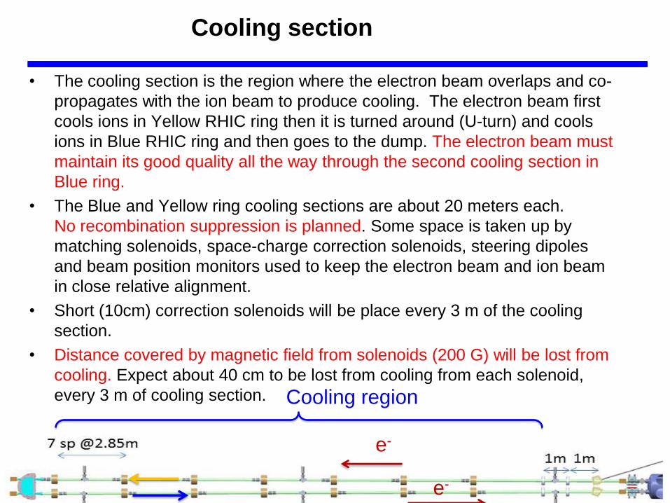
• The cooling section is the region where the electron beam overlaps and co-
propagates with the ion beam to produce cooling. The electron beam first
cools ions in Yellow RHIC ring then it is turned around (U-turn) and cools
ions in Blue RHIC ring and then goes to the dump. The electron beam must
maintain its good quality all the way through the second cooling section in
Blue ring.
• The Blue and Yellow ring cooling sections are about 20 meters each.
No recombination suppression is planned. Some space is taken up by
matching solenoids, space-charge correction solenoids, steering dipoles
and beam position monitors used to keep the electron beam and ion beam
in close relative alignment.
• Short (10cm) correction solenoids will be place every 3 m of the cooling
section.
• Distance covered by magnetic field from solenoids (200 G) will be lost from
cooling. Expect about 40 cm to be lost from cooling from each solenoid,
every 3 m of cooling section.
23
Cooling region
3 m Yellow
Blue
e-
e-
e-
e-
March 2015
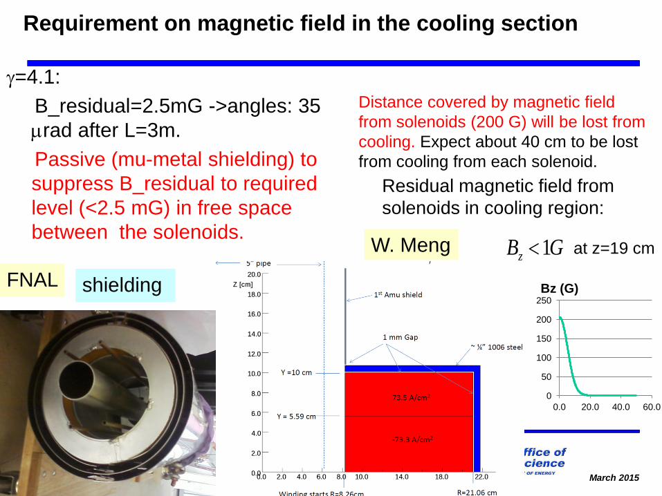
Requirement on magnetic field in the cooling section
g=4.1:
B_residual=2.5mG ->angles: 35
mrad after L=3m.
Passive (mu-metal shielding) to
suppress B_residual to required
level (<2.5 mG) in free space
between the solenoids.
FNAL
GBz 1 at z=19 cm
Residual magnetic field from
solenoids in cooling region:
W. Meng
Distance covered by magnetic field
from solenoids (200 G) will be lost from
cooling. Expect about 40 cm to be lost
from cooling from each solenoid.
shielding
0
50
100
150
200
250
0.0 20.0 40.0 60.0
Bz (G)
March 2015
Effects on hadron beams
• Effects of electron bunches on ion beam dynamics (tune modulation due to
electron beam space-charge) led to requirement to “lock” electron beam on
fixed location within ion bunch to avoid betatron resonances. Remaining
“random noise effect” sets requirements on jitter on electron bunch timing and
bunch current.
• Due to synchrotron motion of ions tune modulation may cause additional
emittance growth due to the synchro-betatron resonances and diffusion due to
the intra-beam scattering. For LEReC, such additional transverse heating has
to be counteracted by electron cooling.
• Hadron beam lifetime in the presence of cooling:
- need to avoid creation of dense core
- lifetime limitations due to the space charge
- interplay of space charge and beam-beam effects
25
March 2015
26
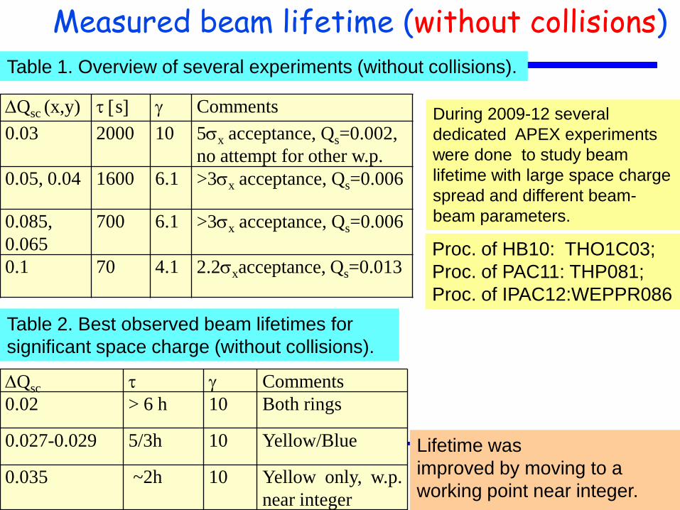
Measured beam lifetime (without collisions) Table 1. Overview of several experiments (without collisions).
Table 2. Best observed beam lifetimes for
significant space charge (without collisions).
Qsc t g Comments
0.02 > 6 h 10 Both rings
0.027-0.029 5/3h 10 Yellow/Blue
0.035 ~2h 10 Yellow only, w.p.
near integer
Qsc (x,y) t [s] g Comments
0.03 2000 10 5x acceptance, Qs=0.002,
no attempt for other w.p.
0.05, 0.04 1600 6.1 >3x acceptance, Qs=0.006
0.085,
0.065
700 6.1 >3x acceptance, Qs=0.006
0.1 70 4.1 2.2xacceptance, Qs=0.013
Lifetime was
improved by moving to a
working point near integer.
Proc. of HB10: THO1C03;
Proc. of PAC11: THP081;
Proc. of IPAC12:WEPPR086
During 2009-12 several
dedicated APEX experiments
were done to study beam
lifetime with large space charge
spread and different beam-
beam parameters.
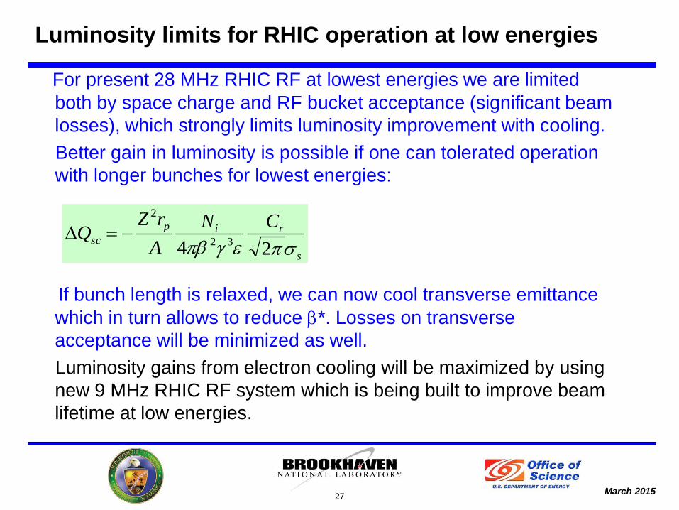
March 2015
For present 28 MHz RHIC RF at lowest energies we are limited
both by space charge and RF bucket acceptance (significant beam
losses), which strongly limits luminosity improvement with cooling.
Better gain in luminosity is possible if one can tolerated operation
with longer bunches for lowest energies:
If bunch length is relaxed, we can now cool transverse emittance
which in turn allows to reduce *. Losses on transverse
acceptance will be minimized as well.
Luminosity gains from electron cooling will be maximized by using
new 9 MHz RHIC RF system which is being built to improve beam
lifetime at low energies.
27
s
rip
sc
CN
A
rZQ
eg 24 32
2
Luminosity limits for RHIC operation at low energies
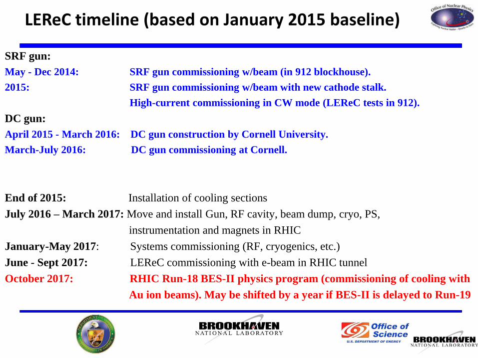
March 2015
SRF gun:
May - Dec 2014: SRF gun commissioning w/beam (in 912 blockhouse).
2015: SRF gun commissioning w/beam with new cathode stalk.
High-current commissioning in CW mode (LEReC tests in 912).
DC gun:
April 2015 - March 2016: DC gun construction by Cornell University.
March-July 2016: DC gun commissioning at Cornell.
End of 2015: Installation of cooling sections
July 2016 – March 2017: Move and install Gun, RF cavity, beam dump, cryo, PS,
instrumentation and magnets in RHIC
January-May 2017: Systems commissioning (RF, cryogenics, etc.)
June - Sept 2017: LEReC commissioning with e-beam in RHIC tunnel
October 2017: RHIC Run-18 BES-II physics program (commissioning of cooling with
Au ion beams). May be shifted by a year if BES-II is delayed to Run-19
LEReC timeline (based on January 2015 baseline)
March 2015
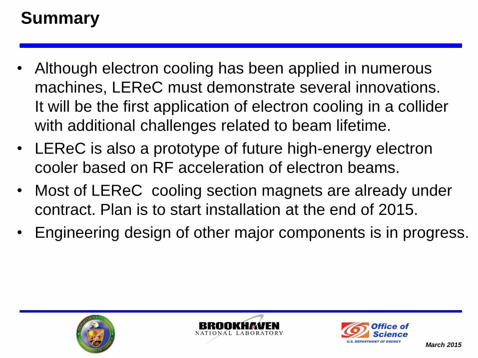
Summary
• Although electron cooling has been applied in numerous
machines, LEReC must demonstrate several innovations.
It will be the first application of electron cooling in a collider
with additional challenges related to beam lifetime.
• LEReC is also a prototype of future high-energy electron
cooler based on RF acceleration of electron beams.
• Most of LEReC cooling section magnets are already under
contract. Plan is to start installation at the end of 2015.
• Engineering design of other major components is in progress.