Embed Size (px)
Citation preview
Page 351
Low Cost Translucent Concrete
B R Harika, M.Tech, AMIE
Assistant Professor,
Department of Civil Engineering,
Gates Institute of Technology,
Gooty, Ananthapurum, A.P.
Ajay Kumar Reddy
B.Tech IV Year Student
Department of Civil Engineering,
Gates Institute of Technology,
Gooty, Ananthapurum, A.P.
ABSTRACT
Translucent concrete aims at providing on energy
concrete based light emitting concrete blocks. This
project is forwarded with an idea of inducting of
optical fibers in the concrete blocks or walls. So that
light on pass from one side to another without
hindering the privacy of occupants.
They after to taking few steps into the project, we
have introduced GGBS(Ground Granulated Blast
Furnence Slag) with partially replacement of cement,
so that we can achieve higher strength parameters at
low cost. Different percentage variations of GGBS
are studied in the project, so that we can get the
optimum percentage at reasonable strength
parameters.
This project mainly enlightens the scope of low cost
building blocks which could transmit light efficiently.
Keywords: Fibers, Translucent, GGBS
INTRODUCTION
Concrete, that traditionally solid, substantial building
material, is getting a makeover. Engineers have now
developed concrete mixtures that are capable of
transmitting light. By switching the ingredients of
traditional concrete with transparent ones, or
embedding fiber optics, translucent concrete has
become a reality. “Light Transmitting concrete also
knows as translucent concrete”. It is the brightest
building material development in recent years. It is one
of the newest, most functional and revolutionary
element in green construction material. In this paper
the manufacturing uses and future scope of transparent
concrete is widely given. However, this innovative
new material, while still partially in the development
stages, is beginning to be used in a variety of
applications in architecture, and promises vast
opportunities in the future.
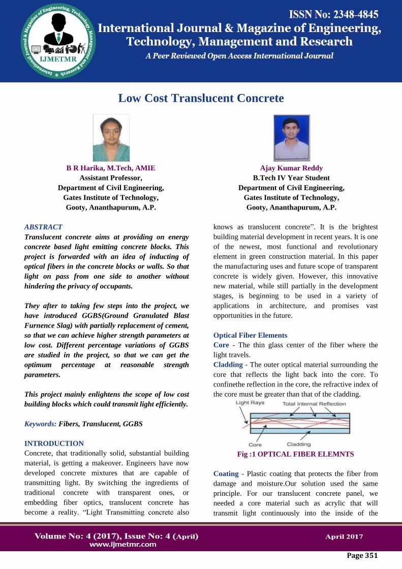
Optical Fiber Elements
Core - The thin glass center of the fiber where the
light travels.
Cladding - The outer optical material surrounding the
core that reflects the light back into the core. To
confinethe reflection in the core, the refractive index of
the core must be greater than that of the cladding.
Fig :1 OPTICAL FIBER ELEMNTS
Coating - Plastic coating that protects the fiber from
damage and moisture.Our solution used the same
principle. For our translucent concrete panel, we
needed a core material such as acrylic that will
transmit light continuously into the inside of the
Page 352
building, a white cladding layer that reflects the light
back into the core and concrete as the protective
coating.
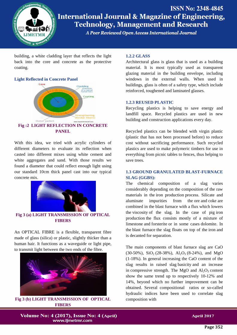
Light Reflected in Concrete Panel
Fig :2 LIGHT REFLECTION IN CONCRETE
PANEL
With this idea, we tried with acrylic cylinders of
different diameters to evaluate its reflection when
casted into different mixes using white cement and
white aggregates and sand. With those results we
found a diameter that could reflect enough light using
our standard 10cm thick panel cast into our typical
concrete mix.
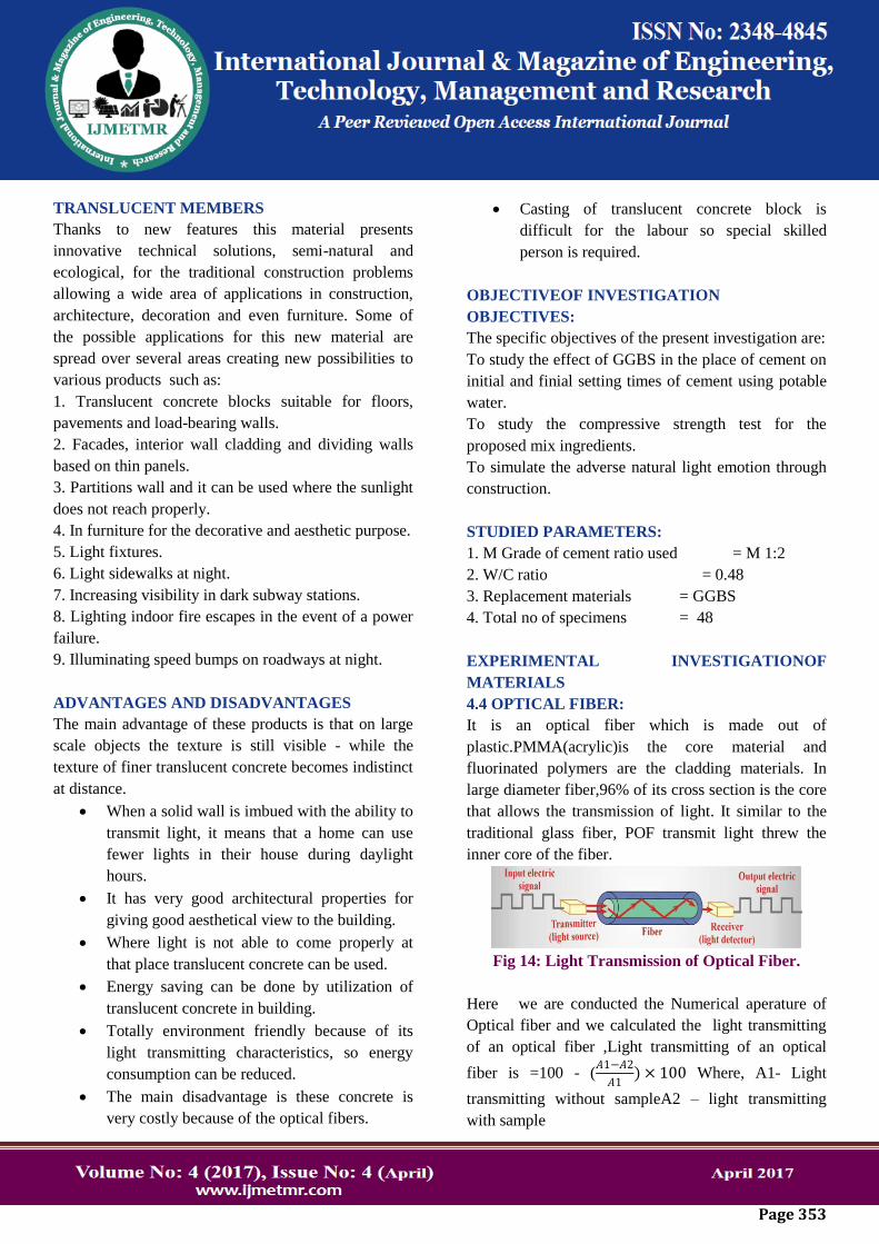
Fig 3 (a) LIGHT TRANSMISSION OF OPTICAL
FIBERS
An OPTICAL FIBRE is a flexible, transparent fibre
made of glass (silica) or plastic, slightly thicker than a
human hair. It functions as a waveguide or light pipe,
to transmit light between the two ends of the fibre.
Fig 3 (b) LIGHT TRANSMISSION OF OPTICAL
FIBERS
1.2.2 GLASS
Architectural glass is glass that is used as a building
material. It is most typically used as transparent
glazing material in the building envelope, including
windows in the external walls. When used in
buildings, glass is often of a safety type, which include
reinforced, toughened and laminated glasses.
1.2.3 REUSED PLASTIC
Recycling plastics is helping to save energy and
landfill space. Recycled plastics are used in new
building and construction applications every day.
Recycled plastics can be blended with virgin plastic
(plastic that has not been processed before) to reduce
cost without sacrificing performance. Such recycled
plastics are used to make polymeric timbers for use in
everything from picnic tables to fences, thus helping to
save trees.
1.3 GROUND GRANULATED BLAST-FURNACE
SLAG (GGBS):
The chemical composition of a slag varies
considerably depending on the composition of the raw
materials in the iron production process. Silicate and
aluminate impurities from the ore and coke are
combined in the blast furnace with a flux which lowers
the viscosity of the slag. In the case of pig iron
production the flux consists mostly of a mixture of
limestone and forsterite or in some cases dolomite. In
the blast furnace the slag floats on top of the iron and
is decanted for separation.
The main components of blast furnace slag are CaO
(30-50%), SiO2 (28-38%), Al2O3 (8-24%), and MgO
(1-18%). In general increasing the CaO content of the
slag results in raised slag basicity and an increase
in compressive strength. The MgO and Al2O3 content
show the same trend up to respectively 10-12% and
14%, beyond which no further improvement can be
obtained. Several compositional ratios or so-called
hydraulic indices have been used to correlate slag
composition with
Page 353
TRANSLUCENT MEMBERS
Thanks to new features this material presents
innovative technical solutions, semi-natural and
ecological, for the traditional construction problems
allowing a wide area of applications in construction,
architecture, decoration and even furniture. Some of
the possible applications for this new material are
spread over several areas creating new possibilities to
various products such as:
1. Translucent concrete blocks suitable for floors,
pavements and load-bearing walls.
2. Facades, interior wall cladding and dividing walls
based on thin panels.
3. Partitions wall and it can be used where the sunlight
does not reach properly.
4. In furniture for the decorative and aesthetic purpose.
5. Light fixtures.
6. Light sidewalks at night.
7. Increasing visibility in dark subway stations.
8. Lighting indoor fire escapes in the event of a power
failure.
9. Illuminating speed bumps on roadways at night.
ADVANTAGES AND DISADVANTAGES
The main advantage of these products is that on large
scale objects the texture is still visible - while the
texture of finer translucent concrete becomes indistinct
at distance.
When a solid wall is imbued with the ability to
transmit light, it means that a home can use
fewer lights in their house during daylight
hours.
It has very good architectural properties for
giving good aesthetical view to the building.
Where light is not able to come properly at
that place translucent concrete can be used.
Energy saving can be done by utilization of
translucent concrete in building.
Totally environment friendly because of its
light transmitting characteristics, so energy
consumption can be reduced.
The main disadvantage is these concrete is
very costly because of the optical fibers.
Casting of translucent concrete block is
difficult for the labour so special skilled
person is required.
OBJECTIVEOF INVESTIGATION
OBJECTIVES:
The specific objectives of the present investigation are:
To study the effect of GGBS in the place of cement on
initial and finial setting times of cement using potable
water.
To study the compressive strength test for the
proposed mix ingredients.
To simulate the adverse natural light emotion through
construction.
STUDIED PARAMETERS:
1. M Grade of cement ratio used = M 1:2
2. W/C ratio = 0.48
3. Replacement materials = GGBS
4. Total no of specimens = 48
EXPERIMENTAL INVESTIGATIONOF
MATERIALS
4.4 OPTICAL FIBER:
It is an optical fiber which is made out of
plastic.PMMA(acrylic)is the core material and
fluorinated polymers are the cladding materials. In
large diameter fiber,96% of its cross section is the core
that allows the transmission of light. It similar to the
traditional glass fiber, POF transmit light threw the
inner core of the fiber.
Fig 14: Light Transmission of Optical Fiber.
Here we are conducted the Numerical aperature of
Optical fiber and we calculated the light transmitting
of an optical fiber ,Light transmitting of an optical
fiber is =100 - (𝐴1−𝐴2
𝐴1) × 100 Where, A1- Light
transmitting without sampleA2 – light transmitting
with sample
Page 354
4.5 GGBS:
The ggbs will be adding the partially replacement of
cement. And the some tests will be conducted on the
ggbs.
The specific gravity of ggbs is determined by
correlating the rise of cement and kerosene levels in
specific gravity bottle. Since, the cement on mixing
with the water hardens so it is mixed with kerosene
and the corresponding rise in bottle for specific gravity
determination is found.
Specific gravity of cement =3.44 and
Fineness modulus =3.66
EXPERIMENTAL METHODOLOGY
5.1 MIX DESIGN:
The Cement mortar has been designed for M Grade
concrete using ISI method. The design procedure is
presented in Appendix – I. The mix obtained is 1:2
with water-cement ratio of 0.48 and total mixed
proportions.
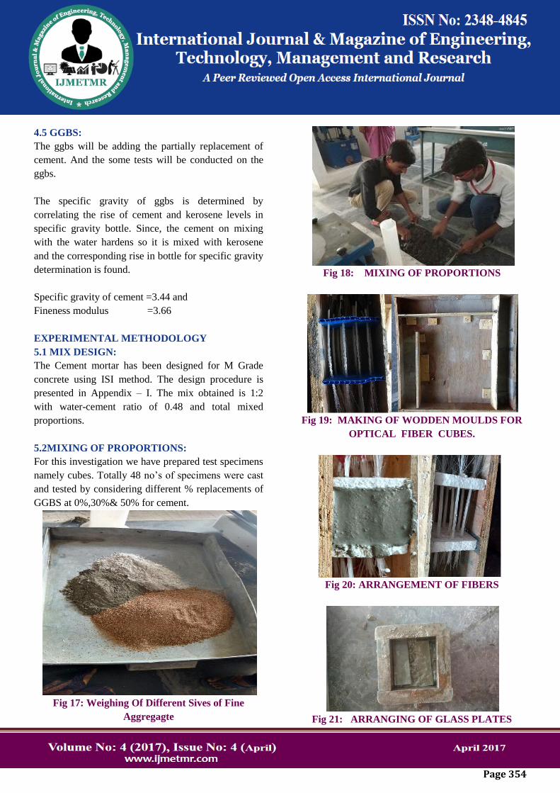
5.2MIXING OF PROPORTIONS:
For this investigation we have prepared test specimens
namely cubes. Totally 48 no’s of specimens were cast
and tested by considering different % replacements of
GGBS at 0%,30%& 50% for cement.
Fig 17: Weighing Of Different Sives of Fine
Aggregagte
Fig 18: MIXING OF PROPORTIONS
Fig 19: MAKING OF WODDEN MOULDS FOR
OPTICAL FIBER CUBES.
Fig 20: ARRANGEMENT OF FIBERS
Fig 21: ARRANGING OF GLASS PLATES
Page 355
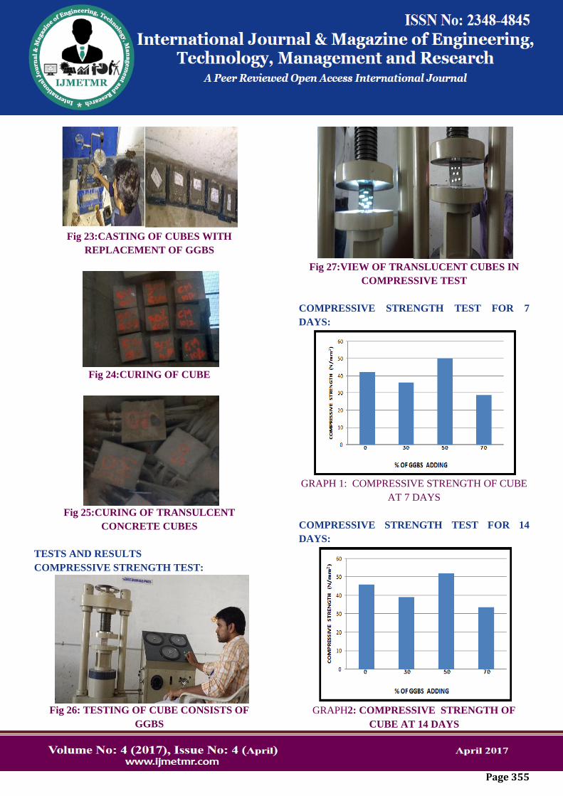
Fig 23:CASTING OF CUBES WITH
REPLACEMENT OF GGBS
Fig 24:CURING OF CUBE
Fig 25:CURING OF TRANSULCENT
CONCRETE CUBES
TESTS AND RESULTS
COMPRESSIVE STRENGTH TEST:
Fig 26: TESTING OF CUBE CONSISTS OF
GGBS
Fig 27:VIEW OF TRANSLUCENT CUBES IN
COMPRESSIVE TEST
COMPRESSIVE STRENGTH TEST FOR 7
DAYS:
GRAPH 1: COMPRESSIVE STRENGTH OF CUBE
AT 7 DAYS
COMPRESSIVE STRENGTH TEST FOR 14
DAYS:
GRAPH2: COMPRESSIVE STRENGTH OF
CUBE AT 14 DAYS
Page 356
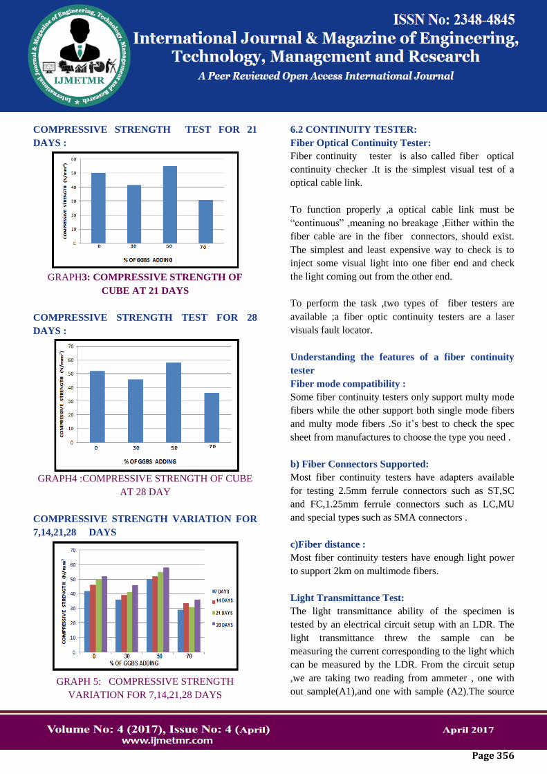
COMPRESSIVE STRENGTH TEST FOR 21
DAYS :
GRAPH3: COMPRESSIVE STRENGTH OF
CUBE AT 21 DAYS
COMPRESSIVE STRENGTH TEST FOR 28
DAYS :
GRAPH4 :COMPRESSIVE STRENGTH OF CUBE
AT 28 DAY
COMPRESSIVE STRENGTH VARIATION FOR
7,14,21,28 DAYS
GRAPH 5: COMPRESSIVE STRENGTH
VARIATION FOR 7,14,21,28 DAYS
6.2 CONTINUITY TESTER:
Fiber Optical Continuity Tester:
Fiber continuity tester is also called fiber optical
continuity checker .It is the simplest visual test of a
optical cable link.
To function properly ,a optical cable link must be
“continuous” ,meaning no breakage ,Either within the
fiber cable are in the fiber connectors, should exist.
The simplest and least expensive way to check is to
inject some visual light into one fiber end and check
the light coming out from the other end.
To perform the task ,two types of fiber testers are
available ;a fiber optic continuity testers are a laser
visuals fault locator.
Understanding the features of a fiber continuity
tester
Fiber mode compatibility :
Some fiber continuity testers only support multy mode
fibers while the other support both single mode fibers
and multy mode fibers .So it’s best to check the spec
sheet from manufactures to choose the type you need .
b) Fiber Connectors Supported:
Most fiber continuity testers have adapters available
for testing 2.5mm ferrule connectors such as ST,SC
and FC,1.25mm ferrule connectors such as LC,MU
and special types such as SMA connectors .
c)Fiber distance :
Most fiber continuity testers have enough light power
to support 2km on multimode fibers.
Light Transmittance Test:
The light transmittance ability of the specimen is
tested by an electrical circuit setup with an LDR. The
light transmittance threw the sample can be
measuring the current corresponding to the light which
can be measured by the LDR. From the circuit setup
,we are taking two reading from ammeter , one with
out sample(A1),and one with sample (A2).The source
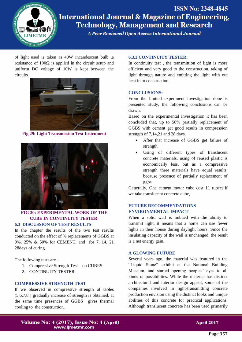
Page 357
of light used is taken as 40W incandescent bulb ,a
resistance of 100Ω is applied in the circuit setup and
uniform DC voltage of 10W is kept between the
circuits.
Fig 29: Light Transmission Test Instrument
FIG 30: EXPERIMENTAL WORK OF THE
CUBE IN CONTINUITY TESTER:
6.3 DISCUSSION OF TEST RESULTS
In the chapter the results of the two test results
conducted on the effect of % replacements of GGBS at
0%, 25% & 50% for CEMENT, and for 7, 14, 21
28days of curing
The following tests are –
1. Compressive Strength Test – on CUBES
2. CONTINUITY TESTER:
COMPRESSIVE STRENGTH TEST
If we observed in compressive strength of tables
(5,6,7,8 ) gradually increase of strength is obtained, at
the same time presences of GGBS gives thermal
cooling to the construction.
6.3.2 CONTINUITY TESTER:
In continuity test , the transmittion of light is more
efficient and very good to the construction, taking of
light through nature and emitting the light with out
heat in to construction.
CONCLUSIONS:
From the limited experiment investigation done is
presented study, the following conclusions can be
drawn.
Based on the experimental investigation it has been
concluded that, up to 50% partially replacement of
GGBS with cement get good results in compression
strength of 7,14,21 and 28 days.
After that increase of GGBS get failure of
strength
Using of different types of translucent
concrete materials, using of reused plastic is
economically less, but as a compressive
strength three materials have equal results,
because presence of partially replacement of
ggbs.
Generally, One cement motar cube cost 11 rupees.If
we take translucent concrete cube,
FUTURE RECOMMENDATIONS
ENVIRONMENTAL IMPACT
When a solid wall is imbued with the ability to
transmit light, it means that a home can use fewer
lights in their house during daylight hours. Since the
insulating capacity of the wall is unchanged, the result
is a net energy gain.
A GLOWING FUTURE
Several years ago, the material was featured in the
“Liquid Stone” exhibit at the National Building
Museum, and started opening peoples’ eyes to all
kinds of possibilities. While the material has distinct
architectural and interior design appeal, some of the
companies involved in light-transmitting concrete
production envision using the distinct looks and unique
abilities of this concrete for practical applications.
Although translucent concrete has been used primarily
Page 358
as an interior decoration, its creators have “visions of
cities that glow from within, and buildings whose
windows need not be flat, rectangular panes, but can
be arbitrary regions of transparency within flowing,
curving walls”. It can at the same time be building
material and light source, can separate and connect,
can be wall or floor, ambient lighting or eye-catcher.
Translucent concrete isalso a great insulating material
that protectsagainst outdoor extreme temperatures
while also letting in daylight. This makes it an
excellent compromise for buildings in harsh climates,
where it can shut out heat or cold without shutting the
building off from daylight. It can be used to illuminate
underground buildings and structures, such as subway
stations & arranging of translucent concrete in zero
energy buildings.
REFERENCES
[1]. Basma F. Bashbash. (2013). “Basics of light
Transmitting Concrete”, pp 079-083, (2013)
[2]. Jianping He. (2011). “Study on Smart Transparent
Concrete Product and its performances”, 6 th
international workshop on advanced smart materials
and smart structures technology, (2011)
[3]. IS: 10262-1982 Recommended Guidelines for
Concrete Mix Design.
[4]. SANTHAKUMAR.A.R, “Concrete Technology”,
Oxford Publishing & Co., New Delhi, 2007, First
Edition.
[5]. Varsharaina. (2013). “A Study on Transparent
Concrete: A Novel Architectural Material to Explore
Construction Sector”, International Journal of
Engineering and Innovative Technology, volume 2,
issue 8, pp83-87, (2013)
[6]. Zhizhou. (2006). “Research and Development of
Plastic Optical Fibre Based Smart Transparent
Concrete”, Proceedings of SPIE, vol. F -1, pp. 7293
72930, (2006)
[7] NEHA R. NAGDIVE & SHEKAR D. BHOLE
“To evaluate properties of translucent concrete /
mortar & their panels”
[8] Allen E and Iano J (2009), “Concrete
Construction”, Fundamentals of Building
Construction: Materials and Methods, Fifth Edition,
Hoboken, New Jersey, John Wiley & Sons Inc. , Ch.
13, pp. 515-551.
[9] How to see through walls: Transparent
concrete is encouraging architects to rethink how they
design buildings. The Economist. Sept. 20, 2001.
Available:
[10] http://www.economist.com/node/779421.
[11] Jeff Hecht, Understanding Fiber Optics, 4th
ed., Prentice-Hall, Upper Saddle River, NJ, USA 2002
[12] (ISBN 0-13-027828-9). National Instruments´
Developer Zone, Light collection and propagation.
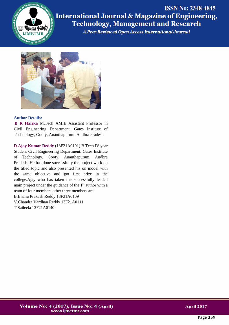
MODEL
FIG 33 : PREPARING OF MODEL
Page 359
Author Details: B R Harika M.Tech AMIE Assistant Professor in
Civil Engineering Department, Gates Institute of
Technology, Gooty, Ananthapurum. Andhra Pradesh
D Ajay Kumar Reddy (13F21A0101) B Tech IV year
Student Civil Engineering Department, Gates Institute
of Technology, Gooty, Ananthapurum. Andhra
Pradesh. He has done successfully the project work on
the titled topic and also presented his on model with
the same objective and got first prize in the
college.Ajay who has taken the successfully leaded
main project under the guidance of the 1st author with a
team of four members other three members are:
B.Bhanu Prakash Reddy 13F21A0109
V.Chandra Vardhan Reddy 13F21A0111
T.Saileela 13F21A0140


![Design and Structural Optimization of Oil Pan - IJMETMR · ric optimization [2]. ... fects of prestress forces on modal parameters of concrete ... oil pan and ANSYS software is used](https://img.pdfslide.us/doc/110x75/5ae1a6127f8b9a5d648bb31f/design-and-structural-optimization-of-oil-pan-optimization-2-fects-of-prestress.jpg)