Embed Size (px)
Citation preview
American Journal of Engineering Research (AJER) 2017
American Journal of Engineering Research (AJER)
e-ISSN: 2320-0847 p-ISSN : 2320-0936
Volume-6, Issue-7, pp-146-151 www.ajer.org
Research Paper Open Access
w w w . a j e r . o r g
Page 146
Low Cost Removable (Plug-In) Electronic Password - Based Door
Lock
Agbo David Odu1, Madukwe Chinaza Alice
2, Otengye Jotham Odinya
3
123Department of Electrical/Electronic Engineering, Federal University of Agriculture, Makurdi, Nigeria
Corresponding Author: Agbo David Odu
Abstract: Security has always been an important factor in life. We need our home and offices to be secure. In
this paper the plug-in electronic door lock is designed to have two levels of security and it comprises two
sections. The first section is mobile section which serves as the key. It contains a matrix keypad, LED, and a
microcontroller; it can be carried around in the pocket while the second section, which is stationary, is installed
at the door. When the mobile section is plugged into the static section, the two sections have a handshake;
without the internal handshake between the two microcontrollers the static section will not accept the mobile
section. If the correct password is entered the door lock will open the door for 15 seconds after which it will
automatically close the door back. If the wrong password is entered three times, the system will keep the door
locked, activate alarm and an SMS will be sent to the authorized personnel to stop the alarm and reset the
system so that password can be entered again. This work can be used for access control in homes and offices
Keywords: Electronic Access Control, Keypad-based, microcontroller – based, Security Door
----------------------------------------------------------------------------------------------------------------------------- ----------
Date of Submission: 14-03-2017 Date of acceptance: 15-07-2017
----------------------------------------------------------------------------------------------------------------------------- ----------
I. INTRODUCTION Doors serve as entrances to our homes, offices and many other kinds of enclosure; they may also
provide access for strangers, criminals and offenders. Doors are meant to be secured and to prevent intrusions
from unwanted persons. Individuals and cooperate bodies are becoming more aware of the dangers associated
with relying on keys and padlocks to provide security to exclusive areas of their apartments and organization,
because criminals and fraudsters can forge keys or make master keys that can be used to break into such rooms
or offices. To eliminate this insecure and old fashioned method, the use of password in doors/gates mechanism
evolved.
Security and Access Management is a very important topic therefore a lot of research has been
conducted on it, especially in the area of door lock. Video technology was incorporated into the access
management system designed by [3]. The camera was used by the appropriate personnel to view the front door
to the home. This camera feeds directly to the mobile phone of the home owner using the cellular network. This
allowed the owner some form of access control to his/her home. The home owner can then interact with a visitor
via alarm systems, chatting with the visitor via video streaming, sending and receiving of messages amongst
others. In [4], the researcher connected the digital lock system with the Internet of Things (IoT) technology. The
use of IoT strengthened thesecurity as the system transfers recorded images to the user’s mobile device when an
unauthorized user attempts to access the area being guarded. This system not only sends information to the
owner when the lock is being physically damaged, it enables the user to remotely operate the door lock.
Access control using face recognition is the main attribute of the system designed in [5]. The system
consists of 3 subsystems: face detection, face recognition and automatic door access control. For a face to be
recognized, it must have been stored in the memory of the system. The door automatically opens for a
recognized face and activates an alarm for an unrecognized face. Bluetooth technology was used in [6], [7], and
[8] to establish connection between the users smart phone and the controller board, while the use of Wi-Fi to
connect devices that are used in electronic door look was proposed by [9] and [10]; the users can lock and
unlock any door in which their system is embedded in, using an android based app on their smart phone and a
Wi-Fi system for communication.

American Journal of Engineering Research (AJER) 2017
w w w . a j e r . o r g
Page 147
This system designed in [11] is composed of a microcontroller based electronic door lock system which
makes use of a matrix keypad & GSM/CDMA network. The password is stored in programmable read only
memory (PROM) so it can be changed at any time. When a person enters the code in the matrix keypad, the
microcontroller verifies the code. If that code is correct the device will open the door. But if someone enters a
wrong code, a red LED will be activated. GSM/CDMA module can be used to operate the device; when anyone
makes a call from his mobile to the receiving device which is set in main circuitry, the system checks and
confirms that the call was from a desired number then the door will be unlocked. An IPS circuit can be used for
giving backup in the case of emergencies resulting from power failure. Palmtop recognition system is the main
user recognition system prescribed in [12]. This works by using extensive image processing thereby reducing
the error probability encountered in fingerprint recognition system
From the above literature reviews, it was noted that the development of a single secret authentication
such as only password entering, is an effective security control, but dual authentication, which has been
developed in this work, is a more effective security control. In this paper, the plug-in electronic password door
lock is divided into two sections: the first section comprises a matrix keypad and LED connected to a
microcontroller [1] which forms the mobile or movable key. The second section comprises of a microcontroller,
GSM module, LCD, relay and a motor which are installed on the door (static). The mobile section can be
plugged into to the static section before the password entering can grant access. The mobile section makes use
of the power from the static section. The keypad is used to enter a password to the system and if the password
entered is correct the door will be opened by motor which is used to rotate the handle of the door lock. Three
attempts are allowed for password to be entered incorrectly before the system locks up and sends an SMS to
authorized personnel to stop the beeping sound of the buzzer and the resetting of the lock. Some features like
adding new users and changing old password are configured by the keypad. An LCD module is used to display
messages to the user.
II. MATERIALS AND METHODS This system is designed to prevent the opening of the door by unauthorized persons. The structure of
home security system contains a matrix keypad, the door latch opener and a GSM modem for the security dial
up interfaced to the microcontroller. The microcontroller receives the input signals from keypads. The keypad
interfaced to the controller is used as the password entry system to open/close the door. The block diagram of
the system is depicted in Figure 1.
Figure 1: Block diagram of the Electronic Plug-In Password Based Security System.
The schematic diagram of the Electronic Plug-In Password Based Security System is shown in Figure
2. The Electronic Plug-In Password Based Security System consists of two sections; the mobile (keypad)
section, and the static section which is installed on the door. The mobile section makes use of the power of the
static section when the mobile section is plugged into the static section. The mobile section comes on and the
microcontroller in the mobile section synchronizes with the microcontroller at the static section. If there is a
handshake between the two microcontrollers, the static section activates the mobile section and displays
welcome message, but if there is no handshake between the two microcontrollers, this indicates that the first
level of security has not been cleared and the mobile section will not be activated. After activation of the mobile
section, static section shows a display for password entering. If the right password is entered from the mobile
section the static section will open the door for 15 seconds and the user can unplug the mobile section then the
door will close automatic. If a wrong password is entered three times from the mobile section, the static section
will activate an alarm continuously and send an SMS to the phone of the authorized personnel. The static section
will permanently shut the door and the alarm will continue to beep until the authorized person sends an SMS to
trigger the alarm off and another SMS to reset the static section so that password can be entered again.
Microcontroller Keypad Unit
LCD
Microcontroller Motor
Relay Unit
Buzzer GSM

American Journal of Engineering Research (AJER) 2017
w w w . a j e r . o r g
Page 148
Figure 2: Electronic Plug-In Password Based Security System arrangement unit.
Figure 3 shows the flowchart of the program executed by the microcontroller. As indicated in the
flowchart the microcontroller polls the input switches (keypad) after the synchronization of the two
microcontrollers. If the password entered is correct the appropriate decision is taken and the system goes back to
monitoring the synchronization of the two microcontrollers in a continuous loop. But if the wrong password is
entered more than the required time (three times), the system initiates a sound alarm, keeping the door locked
and sending SMS to an authorized personal phone. The door will remain closed and the beeping from the buzzer
will continue until a SMS is sent from the authorized personnel to stop the beeping and reset the system.
Figure 3: Flowchart of Electronic Plug – In Door Lock.
C2
C1
D7
14
D6
13
D5
12
D4
11D
31
0D
29
D1
8D
07
E6
RW
5R
S4
VS
S1
VD
D2
VE
E3
LCD1
LM016L
1 2 3
4 5 6
7 8 9
0 #
1 2 3
A
B
C
D
IN12
OUT13
OUT26
OUT311
OUT414
IN27
IN310
IN415
EN11
EN29
VS
8
VSS
16
GND GND
U3
L293D
C3
C4
12
X2
RA0/AN02
RA1/AN13
RA2/AN2/VREF-/CVREF4
RA4/T0CKI/C1OUT6
RA5/AN4/SS/C2OUT7
RE0/AN5/RD8
RE1/AN6/WR9
RE2/AN7/CS10
OSC1/CLKIN13
OSC2/CLKOUT14
RC1/T1OSI/CCP216
RC2/CCP117
RC3/SCK/SCL18
RD0/PSP019
RD1/PSP120
RB7/PGD40
RB6/PGC39
RB538
RB437
RB3/PGM36
RB235
RB134
RB0/INT33
RD7/PSP730
RD6/PSP629
RD5/PSP528
RD4/PSP427
RD3/PSP322
RD2/PSP221
RC7/RX/DT26
RC6/TX/CK25
RC5/SDO24
RC4/SDI/SDA23
RA3/AN3/VREF+5
RC0/T1OSO/T1CKI15
MCLR/Vpp/THV1
U1
PIC16F877A
RA0/AN02
RA1/AN13
RA2/AN2/VREF-/CVREF4
RA4/T0CKI/C1OUT6
RA5/AN4/SS/C2OUT7
RE0/AN5/RD8
RE1/AN6/WR9
RE2/AN7/CS10
OSC1/CLKIN13
OSC2/CLKOUT14
RC1/T1OSI/CCP216
RC2/CCP117
RC3/SCK/SCL18
RD0/PSP019
RD1/PSP120
RB7/PGD40
RB6/PGC39
RB538
RB437
RB3/PGM36
RB235
RB134
RB0/INT33
RD7/PSP730
RD6/PSP629
RD5/PSP528
RD4/PSP427
RD3/PSP322
RD2/PSP221
RC7/RX/DT26
RC6/TX/CK25
RC5/SDO24
RC4/SDI/SDA23
RA3/AN3/VREF+5
RC0/T1OSO/T1CKI15
MCLR/Vpp/THV1
U2
PIC16F877A
12
X1
RV1
1k
LS1
SOUNDER
+8
8.8
SIM Card
SIM900D
S2-1041Y-Z097C
CE0980
Power BTN
ON
NEXT
STATUS
TXD
RXD
www.TheEngineeringProjects.com
GSM1
SIM900D-RED
TXD
RXD
ERROR
TXD3
RXD2
CTS8
RTS7
DSR6
DTR4
DCD1
RI9
P1
COMPIM
C21
C20 C17
C18
TXD
RXD
T1IN11
R1OUT12
T2IN10
R2OUT9
T1OUT14
R1IN13
T2OUT7
R2IN8
C2+
4
C2-
5
C1+
1
C1-
3
VS+2
VS-6
U4
MAX232
TXD
RXD
RXD
TXD
D6
R37
D6
RB0 RB1 RB2
RB4
RB5
RB6
RB7
D6
RB4
RB5
RB6
RB7
RB0
RB1
RB2
+12V+5V
American Journal of Engineering Research (AJER) 2017
w w w . a j e r . o r g
Page 149
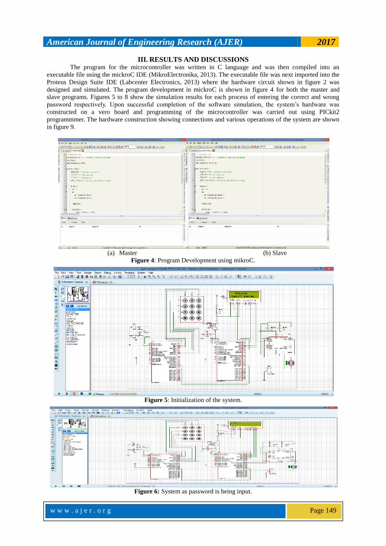
III. RESULTS AND DISCUSSIONS The program for the microcontroller was written in C language and was then compiled into an
executable file using the mickroC IDE (MikroElectronika, 2013). The executable file was next imported into the
Proteus Design Suite IDE (Labcenter Electronics, 2013) where the hardware circuit shown in figure 2 was
designed and simulated. The program development in mickroC is shown in figure 4 for both the master and
slave programs. Figures 5 to 8 show the simulation results for each process of entering the correct and wrong
password respectively. Upon successful completion of the software simulation, the system’s hardware was
constructed on a vero board and programming of the microcontroller was carried out using PICkit2
programmmer. The hardware construction showing connections and various operations of the system are shown
in figure 9.
(a) Master (b) Slave
Figure 4: Program Development using mikroC.
Figure 5: Initialization of the system.
Figure 6: System as password is being input.

American Journal of Engineering Research (AJER) 2017
w w w . a j e r . o r g
Page 150
Figure 7: LCD showing system status with correct password input.
Figure 8: LCD showing system status with wrong password input.
(a) (b)
(c) (d)
Figure 9: Prototype of the System showing various operations.

American Journal of Engineering Research (AJER) 2017
w w w . a j e r . o r g
Page 151
IV. CONCLUSION
The plug - in electronic door lock system was design, simulated and implemented using two pic16f877, a 4x4
matrix keypad, LED, LCD, relay and motor. The two microcontrollers are used to increase the level of security.
The system can be installed at doors in our houses and offices.
REFERENCES [1] PIC16F877 datasheet, 2006. Microchip Technology Inc, 2355 West Chandler Blvd., Chandler, Arizona.11-26pp.
[2] Pickit2 Microchip Technology Inc, 2355 West Chandler Blvd., Chandler, Arizona [3] BurakSarp, TolgaKaralar, HuseyinKusetogullari, “Real Time Smart Door System for Home Security”International Journal of
Scientific Research in Information Systems and Engineering, vol. 1, no. 2, 2015
[4] I. Ha, "Security and Usability Improvement on a Digital Door Lock System based on Internet of
Things", International Journal of Security and Its Applications, vol. 9, no. 8, pp. 45-54, 2015.
[5] H. Lwin, A. Khaing and H. Tun, "Automatic Door Access System Using Face Recognition", International Journal of Scientific & Technology Research, vol. 4, no. 6, 2015.
[6] N. Ismail, Z. Tukiran, N. Shamsuddin and E. Saadon, "Android-based Home Door Locks ApplicationviaBluetooth for Disabled
People", in IEEE International Conference on Control System, Computing andEngineering, Penang, Malaysia, 2014. [7] A. Mishra, S. Sharma, S. Dubey and S.K. Dubey, "PASSWORD BASED SECURITY LOCK SYSTEM", International Journal of
Advanced Technology in Engineering and Science, vol. 2, no. 5, 2014.
[8] N. Majgaonkar, R. Hodekar and P. Bandagale, "Automatic Door Locking System", International Journal of Engineering
Development and Research, vol. 4, no. 1, 2016.
[9] P. Patel and S. Ajani, "The Digital Locking and Unlocking System Based on Android for Smart Phone", International Journal of
Advanced Research in Computer Science and Software Engineering Research, vol. 6, no. 2, 2016. [10] S. Basu, M. Feeroz, D. PR, N. Raun and F. Alam, "Spark Core Based Wireless Remote Door Lock and Multiple Access
Synchronization", International Journal of Advanced Research in Computer Science and Software Engineering Research Paper, vol.
5, no. 4, 2015. [11] M. Mohammad Amanullah, "Microcontroller Based Reprogrammable Digital Door Lock Security System by Using Keypad &
GSM/CDMA Technology", IOSR Journal of Electrical and Electronics Engineering, vol. 4, no. 6, pp. 38-42, 2013.
[12] K. WazedNafi, T. ShekhaKar and S. AnisulHoque, "An Advanced Door Lock Security System using Palmtop Recognition System", International Journal of Computer Applications, vol. 56, no. 17, pp. 18-26, 2012.
[13] MikroElektronika, MikroC, 2013. http://mikroe.com/
[14] Labcenter Electronics, Proteus VSM, 2013. http://www.labcenter.com/
Agbo David Odu. "Low Cost Removable (Plug-In) Electronic Password - Based Door Lock."
American Journal of Engineering Research (AJER) 6.7 (2017): 146-51.