Embed Size (px)
Citation preview
1
LOW COST OPTIONS FOR THE USE
OF HYDROCARBONS IN THE
MANUFACTURE OF
POLYURETHANE FOAMS
AN ASSESSMENT FOR APPLICATION IN MLF
PROJECTS
M A R C H 2 0 1 2
2
Table of Contents
EXECUTIVE SUMMARY 3
1. INTRODUCTION 5
2. DESIGN, EXECUTION 7
3. OUTCOMES 9
3.1 GENERAL INFORMATION 9 3.2 EQUIPMENT DEVELOPMENT AND EVALUATION 11 3.3 SYSTEM DEVELOPMENT AND EVALUATION 12
4. CONCLUSIONS 15
4.1 PRE-BLENDED CYCLO-PENTANE 15 4.2 PRE-BLENDED NORMAL-PENTANE 15 4.3 DIRECTLY INJECTED HYDROCARBONS 15
ATTACHMENTS 16
I. PROCESS SAFETY REQUIREMENTS II. HCFC PHASEOUT TECHNOLOGIES IN PU FOAM APPLICATIONS III. PROJECT DOCUMENT (APPROVED VERSION) IV. NEW APPROACHES FOR HYDROCARBON POLYURETHANE TECHNOLOGY V. REPORT OF DATA GENERATED IN DOW POLYURETHANE SYSTEM HOUSE
LABORATORY WITH DOW SYSTEMS AND SAIP EQUIPMENT FOR PREBLENDED PENTANE AND THIRD STREAM PENTANE INJECTION
VI. FINAL UPDATE ON ABOVE REPORT
3
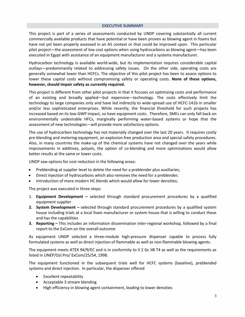
EXECUTIVE SUMMARY
This project is part of a series of assessments conducted by UNDP covering substantially all current commercially available products that have potential or have been proven as blowing agent in foams but have not yet been properly assessed in an A5 context or that could be improved upon. This particular pilot project—the assessment of low cost options when using hydrocarbons as blowing agent—has been executed in Egypt with assistance of an equipment manufacturer and a systems manufacturer.
Hydrocarbon technology is available world-wide, but its implementation requires considerable capital outlays—predominantly related to addressing safety issues. On the other side, operating costs are generally somewhat lower than HCFCs. The objective of this pilot project has been to assess options to lower these capital costs without compromising safety or operating costs. None of these options, however, should impair safety as currently required.
This project is different from other pilot projects in that it focuses on optimizing costs and performance of an existing and broadly applied—but expensive—technology. The costs effectively limit the technology to large companies only and have led indirectly to wide-spread use of HCFC-141b in smaller and/or less sophisticated enterprises. While recently, the financial threshold for such projects has increased based on its low-GWP impact, so have equipment costs. Therefore, SMEs can only fall back on environmentally undesirable HFCs, marginally performing water-based systems or hope that the assessment of new technologies—will provide more satisfactory options.
The use of hydrocarbon technology has not materially changed over the last 20 years. It requires costly pre-blending and metering equipment, an explosion-free production area and special safety procedures. Also, in many countries the make-up of the chemical systems have not changed over the years while improvements in additives, polyols, the option of co-blending and more optimizations would allow better results at the same or lower costs.
UNDP saw options for cost reduction in the following areas:
Preblending at supplier level to delete the need for a preblender plus auxiliaries;
Direct injection of hydrocarbons which also removes the need for a preblender;
Introduction of more modern HC blends which would allow for lower densities;
The project was executed in three steps:
1. Equipment Development – selected through standard procurement procedures by a qualified equipment supplier
2. System Development – selected through standard procurement procedures by a qualified system house including trials at a local foam manufacturer or system house that is willing to conduct these and has the capabilities
3. Reporting – This includes an information dissemination inter-regional workshop, followed by a final report to the ExCom on the overall outcome
As equipment UNDP selected a three-module high-pressure dispenser capable to process fully formulated systems as well as direct injection of flammable as well as non-flammable blowing agents.
The equipment meets ATEX 94/9/EC and is in conformity to II 2 Gc IIB T4 as well as the requirements as listed in UNEP/Ozl.Pro/ ExCom/25/54, 1998.
The equipment functioned in the subsequent trials well for HCFC systems (baseline), preblended systems and direct injection. In particular, the dispenser offered
Excellent repeatability
Acceptable 3 stream blending
High efficiency in blowing agent containment, leading to lower densities
4
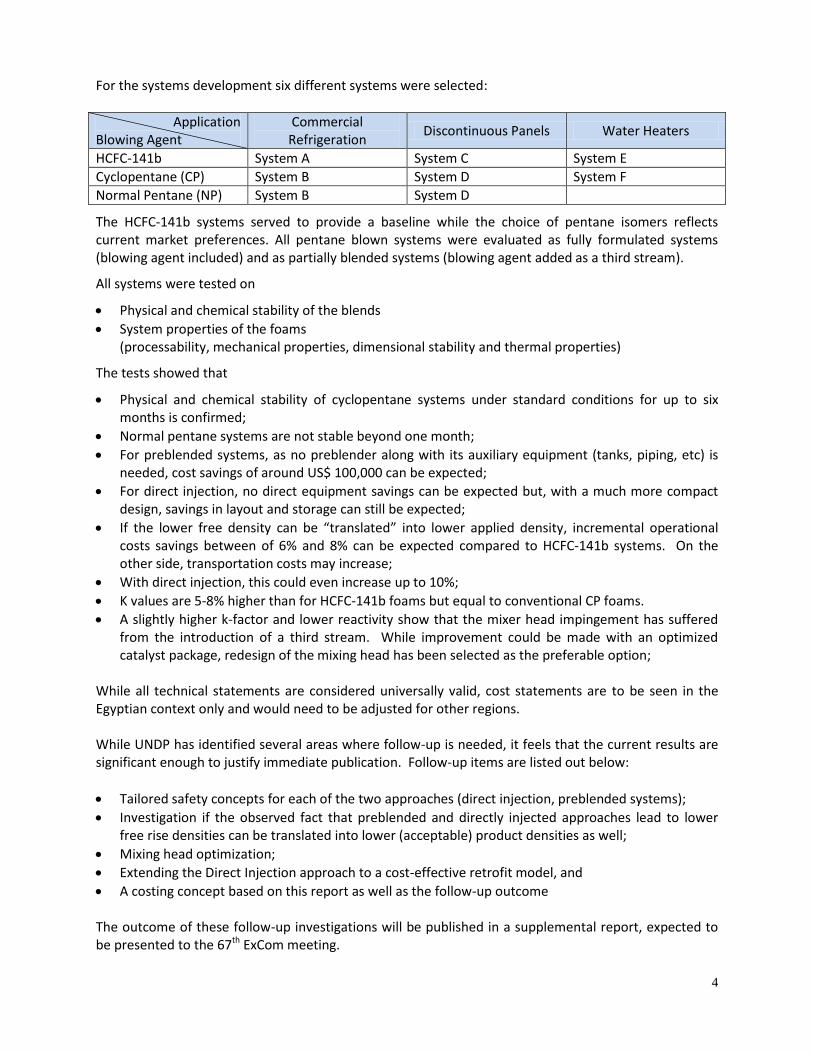
For the systems development six different systems were selected:
Application Blowing Agent
Commercial Refrigeration
Discontinuous Panels Water Heaters
HCFC-141b System A System C System E
Cyclopentane (CP) System B System D System F
Normal Pentane (NP) System B System D
The HCFC-141b systems served to provide a baseline while the choice of pentane isomers reflects current market preferences. All pentane blown systems were evaluated as fully formulated systems (blowing agent included) and as partially blended systems (blowing agent added as a third stream).
All systems were tested on
Physical and chemical stability of the blends
System properties of the foams (processability, mechanical properties, dimensional stability and thermal properties)
The tests showed that
Physical and chemical stability of cyclopentane systems under standard conditions for up to six months is confirmed;
Normal pentane systems are not stable beyond one month;
For preblended systems, as no preblender along with its auxiliary equipment (tanks, piping, etc) is needed, cost savings of around US$ 100,000 can be expected;
For direct injection, no direct equipment savings can be expected but, with a much more compact design, savings in layout and storage can still be expected;
If the lower free density can be “translated” into lower applied density, incremental operational costs savings between of 6% and 8% can be expected compared to HCFC-141b systems. On the other side, transportation costs may increase;
With direct injection, this could even increase up to 10%;
K values are 5-8% higher than for HCFC-141b foams but equal to conventional CP foams.
A slightly higher k-factor and lower reactivity show that the mixer head impingement has suffered from the introduction of a third stream. While improvement could be made with an optimized catalyst package, redesign of the mixing head has been selected as the preferable option;
While all technical statements are considered universally valid, cost statements are to be seen in the Egyptian context only and would need to be adjusted for other regions. While UNDP has identified several areas where follow-up is needed, it feels that the current results are significant enough to justify immediate publication. Follow-up items are listed out below:
Tailored safety concepts for each of the two approaches (direct injection, preblended systems);
Investigation if the observed fact that preblended and directly injected approaches lead to lower free rise densities can be translated into lower (acceptable) product densities as well;
Mixing head optimization;
Extending the Direct Injection approach to a cost-effective retrofit model, and
A costing concept based on this report as well as the follow-up outcome The outcome of these follow-up investigations will be published in a supplemental report, expected to be presented to the 67th ExCom meeting.
5
1. Introduction HCFCs are currently still in use in developing (“A5”) countries as blowing agents in polyurethane (PU) foams. To replace these HCFCs, following criteria would ideally apply:
Chemically /physically stable,
Soluble in the formulation,
A suitable boiling point with 250C being the target,
Low thermal conductivity in the vapor phase,
Non flammable,
Low toxicity,
Zero ODP,
Low GWP,
Low diffusion rate,
Based on validated technology,
Commercially available,
Acceptable in processing, and
Economically viable. CFC phaseout in rigid and integral skin foams has been mostly achieved by replacement through
Hydrochlorofluorocarbons (HCFCs)
Hydrocarbons (HCs)
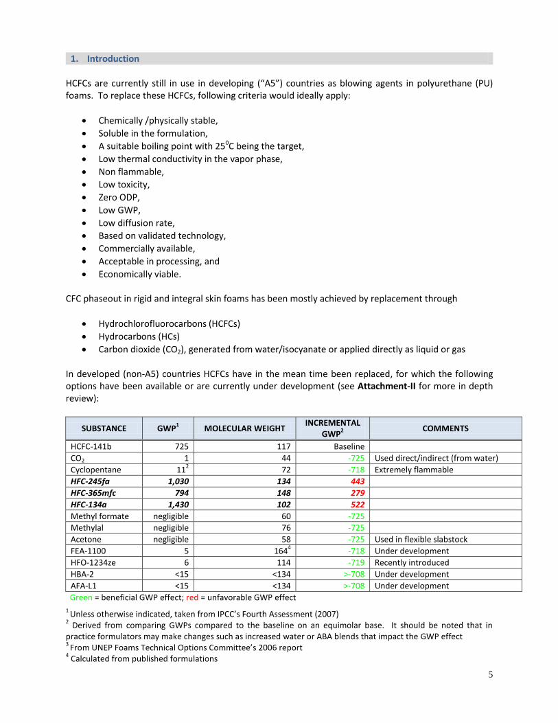
Carbon dioxide (CO2), generated from water/isocyanate or applied directly as liquid or gas In developed (non-A5) countries HCFCs have in the mean time been replaced, for which the following options have been available or are currently under development (see Attachment-II for more in depth review):
SUBSTANCE GWP1 MOLECULAR WEIGHT
INCREMENTAL GWP
2 COMMENTS
HCFC-141b 725 117 Baseline
CO2 1 44 -725 Used direct/indirect (from water)
Cyclopentane 112 72 -718 Extremely flammable
HFC-245fa 1,030 134 443
HFC-365mfc 794 148 279
HFC-134a 1,430 102 522
Methyl formate negligible
60 -725
Methylal negligible 76 -725
Acetone negligible 58 -725 Used in flexible slabstock
FEA-1100
5 1644 -718 Under development
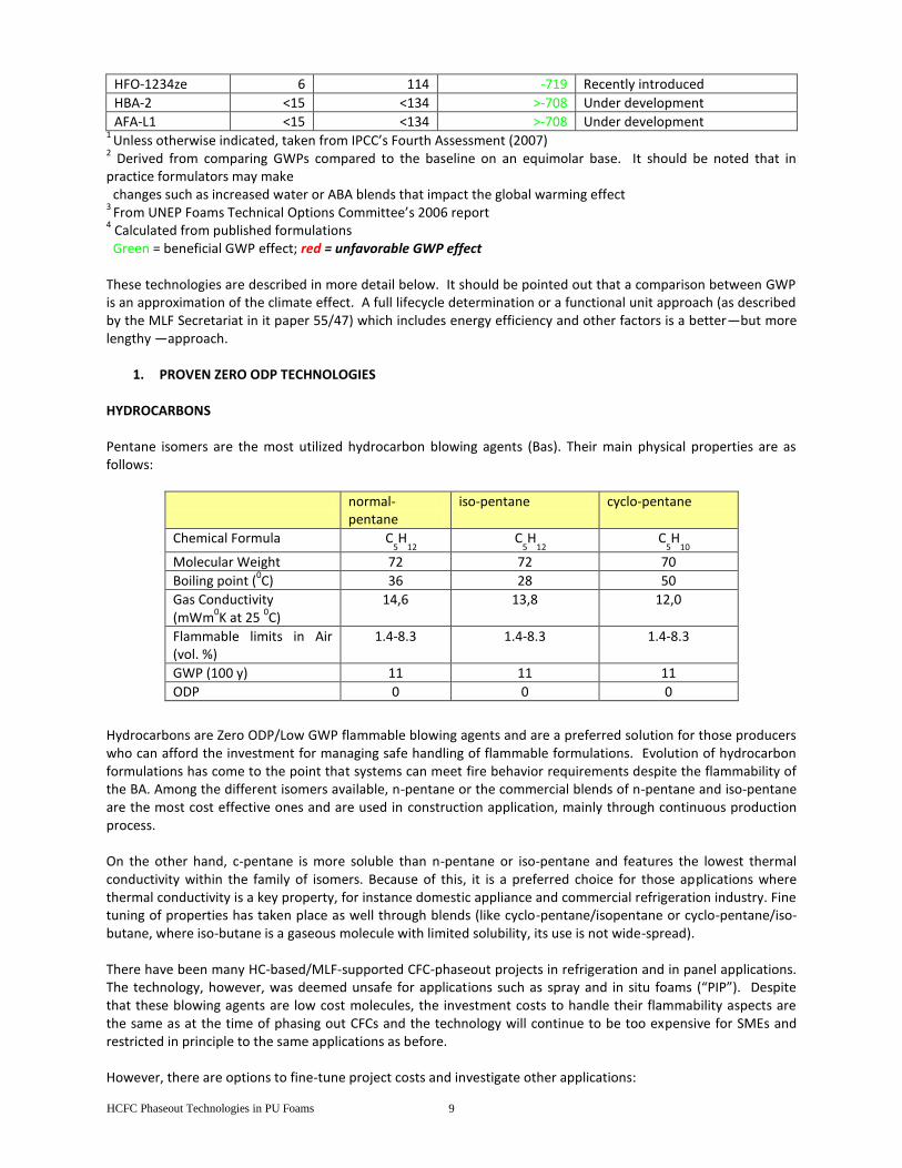
HFO-1234ze 6 114 -719 Recently introduced
HBA-2 <15 <134 >-708 Under development
AFA-L1 <15 <134 >-708 Under development
Green = beneficial GWP effect; red = unfavorable GWP effect
1 Unless otherwise indicated, taken from IPCC’s Fourth Assessment (2007)
2 Derived from comparing GWPs compared to the baseline on an equimolar base. It should be noted that in
practice formulators may make changes such as increased water or ABA blends that impact the GWP effect 3
From UNEP Foams Technical Options Committee’s 2006 report 4 Calculated from published formulations
6
With water not satisfactory performing in thermal insulation applications, HFCs high in GWP, hydrocarbons high in investment costs, and HFOs not yet completely developed and/or not yet commercially available in developing countries, there is a need to assess other potential alternatives and, therefore, to investigate newly emerged technologies on their technical, cost, availability and environmental performance. Decision 55/43 of the Executive Committee of the Multilateral Fund for the Implementation of the Montreal Protocol (“MLF”) reflects this by promoting pilot projects aimed at validating technologies in a developing country (“A5”) context. UNDP has prepared a series of pilot projects which, it believes, cover substantially all current commercially available products that have potential or have been proven as blowing agent in foams but have not yet been assessed in an A5 context or that could be improved upon. From the mentioned pilot projects, the assessment of the use of methyl formate (MF) and methylal in non-continuous PU applications have been technically completed while the assessment of cost-effective HC technologies has been substantially completed and the use of HFO-1234ze in extruded polystyrene plank is in the final stage with all experimental work done. This particular pilot project—the assessment of low cost options when using hydrocarbons as blowing agent—has been executed along with SAIP, an Italian manufacturer of PU foam equipment and Dow Chemical, through its System Development Center in Italy and its system house in Egypt. Hydrocarbon technology is available world-wide, but its implementation requires considerable capital outlays—predominantly related to addressing safety issues. On the other side, operating costs are generally somewhat lower than HCFCs. The objective of this pilot project is to assess options to lower these capital costs without compromising safety or operating costs. This assessment addresses in sequence
Design and Execution
Health, Safety, Environment
Processability
Physical properties
Conversion costs
Conclusions
UNDP acknowledges with appreciation the cooperation extended by its project partners: SAIP (Italy) and Dow Chemical (Italy and Egypt).
While UNDP has identified several areas where follow-up is needed, it feels that the current results are significant enough to justify immediate publication. Follow-up items are listed out below:
Tailored safety concepts for each of the two approaches (direct injection, preblended systems);
Investigation if the observed fact that preblended and directly injected approaches lead to lower free rise densities can be translated into lower (acceptable) product densities as well;
Mixing head optimization;
Extending the Direct Injection approach to a cost-effective retrofit model, and
A costing concept based on this report as well as the follow-up outcome
The outcome of these follow-up investigations will be published in a supplemental report, expected to be presented to the 67th ExCom meeting.
7
2. Design, Execution
The objectives of this project have been to:
1. Develop, optimize and validate low cost options for hydrocarbons as auxiliary blowing agent in polyurethane foam applications;
2. To demonstrate the technology in downstream applications, and 3. To transfer information collected to interested system houses and downstream users
It should be stated upfront that none of these options should impair safety as currently required. It is referred in this context to international standard IEC 79-10,
second edition (1986) and to MLF paper UNEP/Ozl.Pro/ ExCom/25/54, 1998
These safety requirements are summarized in Attachment-I.
Technology assessment is a global task. However, it has to be executed in a particular country. UNDP choose Egypt—and the Government of Egypt accepted—for the following reasons:
HC technology is well established in Egypt
The center of HC development—Europe—is close
UNDP has a long tradition in working with the Egyptian foam industry
This project is different from other pilot projects that focus on HCFC replacement technologies in polyurethane foams. In these other projects, the technology to be assessed is a new one, which requires development of formulations for all applications. In the HC case, the base technology exists for quite a while—since around 1992—and has been broadly applied in non-A5 as well as A5 contexts in companies that would meet critical size and technical proficiency. In praxis this meant that a company should use at least 50t/y HCFCs and have adequate in-house engineering capabilities. This would translate in eligibility for a grant of (7.83 x 50,000 =) US$ 391,000 which approximated the costs of such a project. For domestic refrigeration plants, which cost more because of the need of (expensive) retrofit of jigs, a higher threshold was set. This effectively limited the technology to large companies only and led indirectly to wide-spread use of HCFC-141b in smaller and/or less sophisticated enterprises. Recently, the financial threshold has increased by 25% in case a project is based on a low-GWP technology—which is the case with hydrocarbons--but so have equipment costs. Therefore, even with a new threshold, if the cost of hydrocarbon technology is not lowered, SMEs can only fall back on environmentally undesirable HFCs, marginally performing water-based systems or hope that the assessment of new technologies—will provide more satisfactory options.
The use of hydrocarbon technology has not materially changed over the last 20 years. It requires costly pre-blending and metering equipment, an explosion-free production area and elaborate safety procedures. Also, in many countries the make-up of the chemical systems is unchanged while elsewhere significant system optimization has taken place (additives, special polyols, co-blending, ….).
UNDP saw options for cost reduction in the following areas:
Preblending at supplier level would delete the need for a preblender plus auxiliaries—but cause increase in the system price;
Direct injection of hydrocarbons would also remove the need for a preblender—but increase the equipment cost;
Introduction of modern HC blends would allow for lower densities—and lower in this way operating costs.
To test the feasibility of these concepts, the development and commercialization both of stable pre-blends that can be safely transported and the development of a multi-purpose, three-component foam dispenser are required.
8
The project was designed in four steps: 1. development, optimization and validation/demonstration of premixed, stabilized, modern
hydrocarbons systems that can be used directly by foam manufacturers (which means that the blowing agent is incorporated) or used together with direct injection of the blowing agent
2. development of a three component foam dispenser, capable to direct inject hydrocarbons (pentane of cyclopentane blends)
3. placing the three-component dispenser at a suitable facility followed by trials with a. direct injection of the blowing agent b. using a fully preblended polyol system1
4. demonstration of the technology followed by dissemination through an inter-regional workshop Other PU pilot projects carry a second phase to demonstrate commercial application. In this case, there is no need. The system development part will be an optimization based on knowledge that is already available and incremental success is virtually assured. Building a three component foaming unit has been before applied in an MLF project through retrofit (Turkey, in an ICF project) and will be rather a design optimization than application of a new concept. Also, there is no need to demonstrate the two technology versions in all foam applications. The variations in required formulations are well known to the chemical suppliers that cater to HC systems. As mentioned before, hydrocarbons are highly flammable. UNDP considers the process at the system house (blending) and at user level (processing) hazardous and requiring adequate safeguards. UNDP requires a safety audit to be conducted prior to commercial operation of a converted plant. The actual implementation allowed for some consolidation of the four mentioned steps: 1. Equipment Development – selected through standard procurement procedures by a qualified
equipment supplier selected through standard procurement 2. System Development – selected through standard procurement procedures by a qualified system
house including trials at a local foam manufacturer or system house that is willing to conduct these and has the capabilities
3. Reporting – This includes an information dissemination inter-regional workshop, followed by a final report to the ExCom on the overall outcome
The bidding process led to the selection of SAIP/Pozzi-Ariozo for both system and equipment development. SAIP/Pozzi suggested—and UNDP accepted—to team up for its system development with Dow Systems, Italy and for trials with Dow Systems, Egypt. This arrangement has worked out very well as will be shown in this report and UNDP wants to express its appreciation to the project collaborators. For more details on design, related budget, etc., it is referred to the project document in its approved version (ATTACHMENT-III).
1 (in addition, HCFC formulations have to be run to establish a baseline for comparison)
9
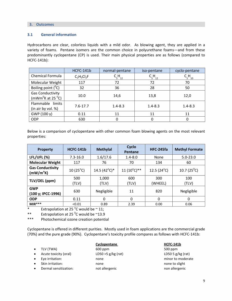
3. Outcomes 3.1 General information Hydrocarbons are clear, colorless liquids with a mild odor. As blowing agent, they are applied in a variety of foams. Pentane isomers are the common choice in polyurethane foams—and from these predominantly cyclopentane (CP) is used. Their main physical properties are as follows (compared to HCFC-141b):
HCFC-141b normal-pentane iso-pentane cyclo-pentane
Chemical Formula C2H3Cl2F C5H
12 C
5H
12 C
5H
10
Molecular Weight 117 72 72 70
Boiling point (0C) 32 36 28 50
Gas Conductivity (mWm0K at 25 0C)
10.0 14,6 13,8 12,0
Flammable limits (in air by vol. %)
7.6-17.7 1.4-8.3 1.4-8.3 1.4-8.3
GWP (100 y) 0.11 11 11 11
ODP 630 0 0 0
Below is a comparison of cyclopentane with other common foam blowing agents on the most relevant properties:
Property HCFC-141b Methylal Cyclo
Pentane HFC-245fa Methyl Formate
LFL/UFL (%) 7.3-16.0 1.6/17.6 1.4-8.0 None 5.0-23.0
Molecular Weight 117 76 70 134 60
Gas Conductivity (mW/moK)
10 (25oC) 14.5 (42oC)* 11 (10oC)** 12.5 (24oC) 10.7 (250C)
TLV/OEL (ppm) 500
(TLV) 1,000 (TLV)
600 (TLV)
300 (WHEEL)
100 (TLV)
GWP (100 y; IPCC-1996)
630 Negligible 11 820 Negligible
ODP 0.11 0 0 0 0 MIR*** <0.01 0.89 2.39 0.00 0.06
* Extrapolation at 25 oC would be ~ 11; ** Extrapolation at 25 0C would be ~13.9 *** Photochemical ozone creation potential
Cyclopentane is offered in different purities. Mostly used in foam applications are the commercial grade (70%) and the pure grade (90%). Cyclopentane’s toxicity profile compares as follows with HCFC-141b: Cyclopentane HCFC-141b
TLV (TWA) 600 ppm 500 ppm
Acute toxicity (oral) LD50 >5 g/kg (rat) LD50 5 g/kg (rat)
Eye irritation: none minor to moderate
Skin irritation: none none to slight
Dermal sensitization: not allergenic non allergenic
10
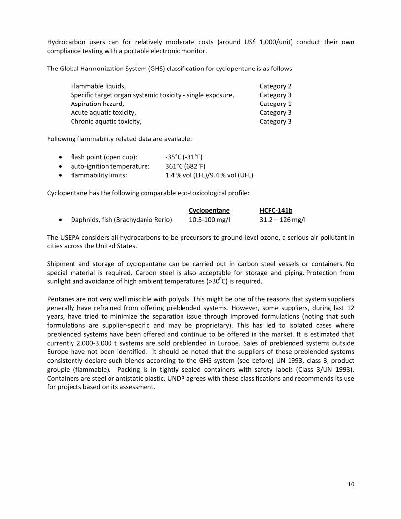
Hydrocarbon users can for relatively moderate costs (around US$ 1,000/unit) conduct their own compliance testing with a portable electronic monitor. The Global Harmonization System (GHS) classification for cyclopentane is as follows
Flammable liquids, Category 2 Specific target organ systemic toxicity - single exposure, Category 3 Aspiration hazard, Category 1 Acute aquatic toxicity, Category 3 Chronic aquatic toxicity, Category 3
Following flammability related data are available:
flash point (open cup): -35°C (-31°F)
auto-ignition temperature: 361°C (682°F)
flammability limits: 1.4 % vol (LFL)/9.4 % vol (UFL) Cyclopentane has the following comparable eco-toxicological profile:
Cyclopentane HCFC-141b
Daphnids, fish (Brachydanio Rerio) 10.5-100 mg/l 31.2 – 126 mg/l The USEPA considers all hydrocarbons to be precursors to ground-level ozone, a serious air pollutant in cities across the United States. Shipment and storage of cyclopentane can be carried out in carbon steel vessels or containers. No special material is required. Carbon steel is also acceptable for storage and piping. Protection from sunlight and avoidance of high ambient temperatures (>300C) is required. Pentanes are not very well miscible with polyols. This might be one of the reasons that system suppliers generally have refrained from offering preblended systems. However, some suppliers, during last 12 years, have tried to minimize the separation issue through improved formulations (noting that such formulations are supplier-specific and may be proprietary). This has led to isolated cases where preblended systems have been offered and continue to be offered in the market. It is estimated that currently 2,000-3,000 t systems are sold preblended in Europe. Sales of preblended systems outside Europe have not been identified. It should be noted that the suppliers of these preblended systems consistently declare such blends according to the GHS system (see before) UN 1993, class 3, product groupie (flammable). Packing is in tightly sealed containers with safety labels (Class 3/UN 1993). Containers are steel or antistatic plastic. UNDP agrees with these classifications and recommends its use for projects based on its assessment.
11
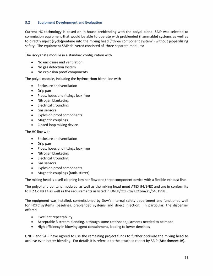
3.2 Equipment Development and Evaluation Current HC technology is based on in-house preblending with the polyol blend. SAIP was selected to commission equipment that would be able to operate with preblended (flammable) systems as well as to directly inject (cyclo)pentane into the mixing head (“three component system”) without jeopardizing safety. The equipment SAIP delivered consisted of three separate modules: The isocyanate module in a standard configuration with
No enclosure and ventilation
No gas detection system
No explosion proof components
The polyol module, including the hydrocarbon blend line with
Enclosure and ventilation
Drip pan
Pipes, hoses and fittings leak-free
Nitrogen blanketing
Electrical grounding
Gas sensors
Explosion proof components
Magnetic couplings
Closed loop mixing device
The HC line with
Enclosure and ventilation
Drip pan
Pipes, hoses and fittings leak-free
Nitrogen blanketing
Electrical grounding
Gas sensors
Explosion proof components
Magnetic couplings (tank, stirrer)
The mixing head is a self-cleaning laminar flow one three component device with a flexible exhaust line.
The polyol and pentane modules as well as the mixing head meet ATEX 94/9/EC and are in conformity to II 2 Gc IIB T4 as well as the requirements as listed in UNEP/Ozl.Pro/ ExCom/25/54, 1998. The equipment was installed, commissioned by Dow’s internal safety department and functioned well for HCFC systems (baseline), preblended systems and direct injection. In particular, the dispenser offered
Excellent repeatability
Acceptable 3 stream blending, although some catalyst adjustments needed to be made
High efficiency in blowing agent containment, leading to lower densities UNDP and SAIP have agreed to use the remaining project funds to further optimize the mixing head to achieve even better blending. For details it is referred to the attached report by SAIP (Attachment-IV).
12
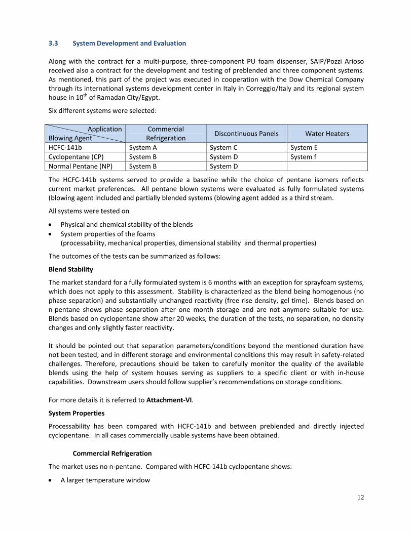
3.3 System Development and Evaluation Along with the contract for a multi-purpose, three-component PU foam dispenser, SAIP/Pozzi Arioso received also a contract for the development and testing of preblended and three component systems. As mentioned, this part of the project was executed in cooperation with the Dow Chemical Company through its international systems development center in Italy in Correggio/Italy and its regional system house in 10th of Ramadan City/Egypt.
Six different systems were selected:
Application Blowing Agent
Commercial Refrigeration
Discontinuous Panels Water Heaters
HCFC-141b System A System C System E
Cyclopentane (CP) System B System D System f
Normal Pentane (NP) System B System D
The HCFC-141b systems served to provide a baseline while the choice of pentane isomers reflects current market preferences. All pentane blown systems were evaluated as fully formulated systems (blowing agent included and partially blended systems (blowing agent added as a third stream.
All systems were tested on
Physical and chemical stability of the blends
System properties of the foams (processability, mechanical properties, dimensional stability and thermal properties)
The outcomes of the tests can be summarized as follows:
Blend Stability
The market standard for a fully formulated system is 6 months with an exception for sprayfoam systems, which does not apply to this assessment. Stability is characterized as the blend being homogenous (no phase separation) and substantially unchanged reactivity (free rise density, gel time). Blends based on n-pentane shows phase separation after one month storage and are not anymore suitable for use. Blends based on cyclopentane show after 20 weeks, the duration of the tests, no separation, no density changes and only slightly faster reactivity. It should be pointed out that separation parameters/conditions beyond the mentioned duration have not been tested, and in different storage and environmental conditions this may result in safety-related challenges. Therefore, precautions should be taken to carefully monitor the quality of the available blends using the help of system houses serving as suppliers to a specific client or with in-house capabilities. Downstream users should follow supplier’s recommendations on storage conditions. For more details it is referred to Attachment-VI.
System Properties
Processability has been compared with HCFC-141b and between preblended and directly injected cyclopentane. In all cases commercially usable systems have been obtained.
Commercial Refrigeration
The market uses no n-pentane. Compared with HCFC-141b cyclopentane shows:
A larger temperature window
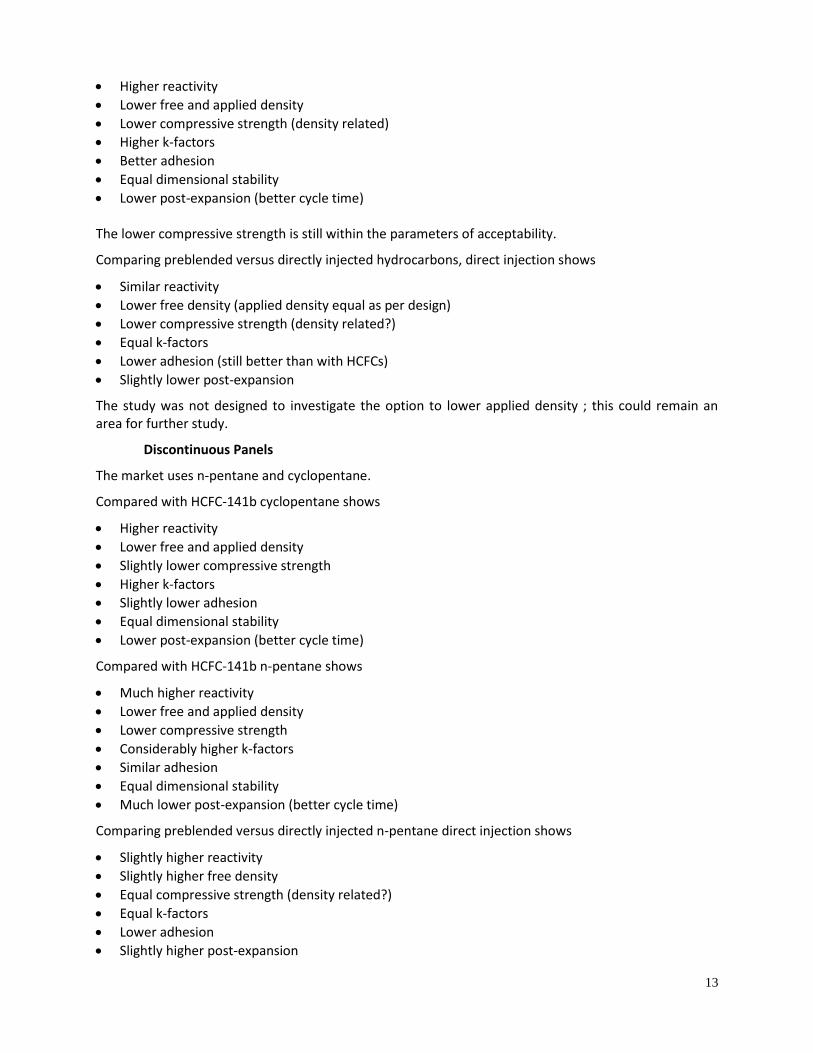
13
Higher reactivity
Lower free and applied density
Lower compressive strength (density related)
Higher k-factors
Better adhesion
Equal dimensional stability
Lower post-expansion (better cycle time) The lower compressive strength is still within the parameters of acceptability.
Comparing preblended versus directly injected hydrocarbons, direct injection shows
Similar reactivity
Lower free density (applied density equal as per design)
Lower compressive strength (density related?)
Equal k-factors
Lower adhesion (still better than with HCFCs)
Slightly lower post-expansion
The study was not designed to investigate the option to lower applied density ; this could remain an area for further study.
Discontinuous Panels
The market uses n-pentane and cyclopentane.
Compared with HCFC-141b cyclopentane shows
Higher reactivity
Lower free and applied density
Slightly lower compressive strength
Higher k-factors
Slightly lower adhesion
Equal dimensional stability
Lower post-expansion (better cycle time)
Compared with HCFC-141b n-pentane shows
Much higher reactivity
Lower free and applied density
Lower compressive strength
Considerably higher k-factors
Similar adhesion
Equal dimensional stability
Much lower post-expansion (better cycle time)
Comparing preblended versus directly injected n-pentane direct injection shows
Slightly higher reactivity
Slightly higher free density
Equal compressive strength (density related?)
Equal k-factors
Lower adhesion
Slightly higher post-expansion
14
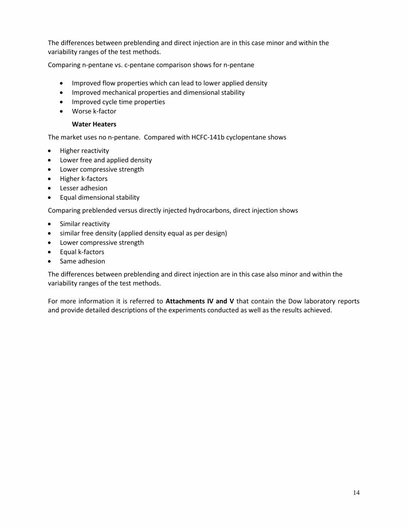
The differences between preblending and direct injection are in this case minor and within the variability ranges of the test methods.
Comparing n-pentane vs. c-pentane comparison shows for n-pentane
Improved flow properties which can lead to lower applied density
Improved mechanical properties and dimensional stability
Improved cycle time properties
Worse k-factor
Water Heaters
The market uses no n-pentane. Compared with HCFC-141b cyclopentane shows
Higher reactivity
Lower free and applied density
Lower compressive strength
Higher k-factors
Lesser adhesion
Equal dimensional stability
Comparing preblended versus directly injected hydrocarbons, direct injection shows
Similar reactivity
similar free density (applied density equal as per design)
Lower compressive strength
Equal k-factors
Same adhesion
The differences between preblending and direct injection are in this case also minor and within the variability ranges of the test methods. For more information it is referred to Attachments IV and V that contain the Dow laboratory reports and provide detailed descriptions of the experiments conducted as well as the results achieved.
15
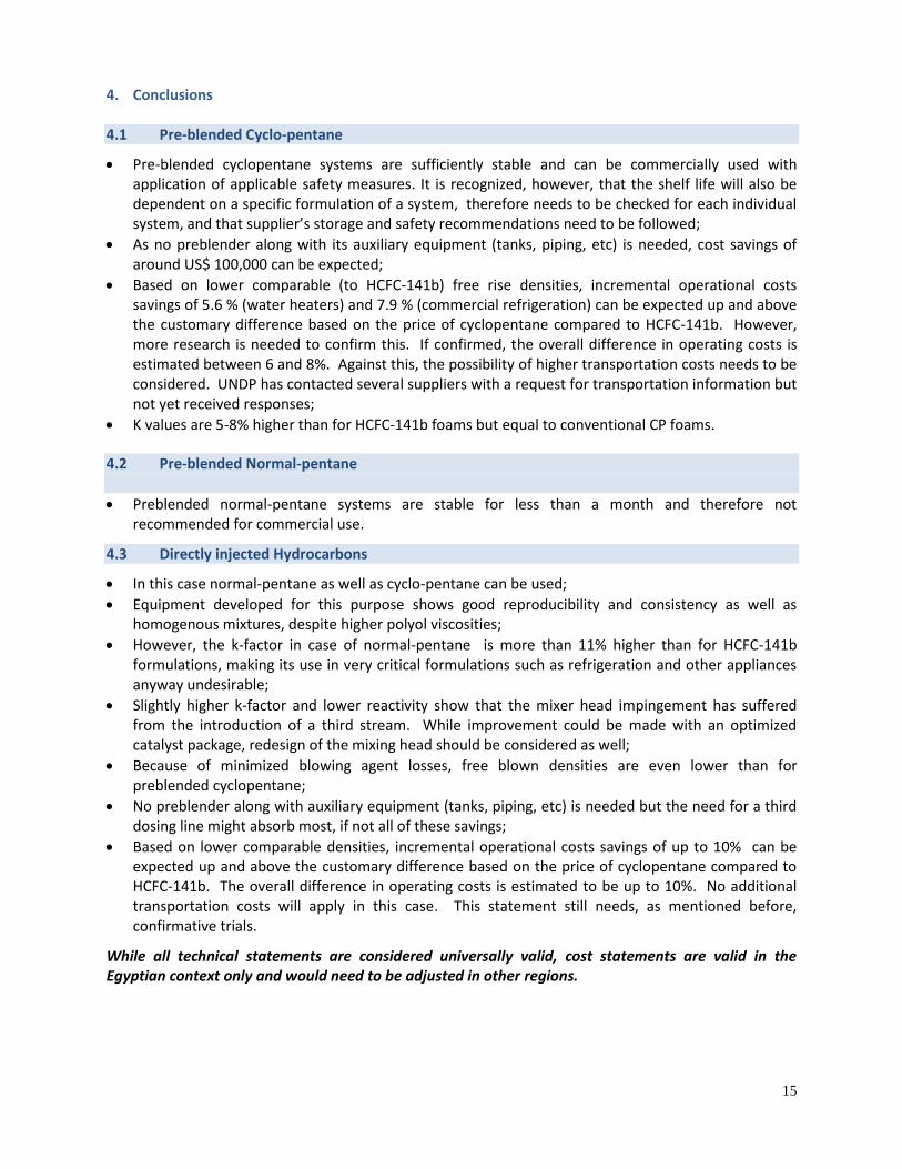
4. Conclusions 4.1 Pre-blended Cyclo-pentane
Pre-blended cyclopentane systems are sufficiently stable and can be commercially used with application of applicable safety measures. It is recognized, however, that the shelf life will also be dependent on a specific formulation of a system, therefore needs to be checked for each individual system, and that supplier’s storage and safety recommendations need to be followed;
As no preblender along with its auxiliary equipment (tanks, piping, etc) is needed, cost savings of around US$ 100,000 can be expected;
Based on lower comparable (to HCFC-141b) free rise densities, incremental operational costs savings of 5.6 % (water heaters) and 7.9 % (commercial refrigeration) can be expected up and above the customary difference based on the price of cyclopentane compared to HCFC-141b. However, more research is needed to confirm this. If confirmed, the overall difference in operating costs is estimated between 6 and 8%. Against this, the possibility of higher transportation costs needs to be considered. UNDP has contacted several suppliers with a request for transportation information but not yet received responses;
K values are 5-8% higher than for HCFC-141b foams but equal to conventional CP foams.
4.2 Pre-blended Normal-pentane
Preblended normal-pentane systems are stable for less than a month and therefore not recommended for commercial use.
4.3 Directly injected Hydrocarbons
In this case normal-pentane as well as cyclo-pentane can be used;
Equipment developed for this purpose shows good reproducibility and consistency as well as homogenous mixtures, despite higher polyol viscosities;
However, the k-factor in case of normal-pentane is more than 11% higher than for HCFC-141b formulations, making its use in very critical formulations such as refrigeration and other appliances anyway undesirable;
Slightly higher k-factor and lower reactivity show that the mixer head impingement has suffered from the introduction of a third stream. While improvement could be made with an optimized catalyst package, redesign of the mixing head should be considered as well;
Because of minimized blowing agent losses, free blown densities are even lower than for preblended cyclopentane;
No preblender along with auxiliary equipment (tanks, piping, etc) is needed but the need for a third dosing line might absorb most, if not all of these savings;
Based on lower comparable densities, incremental operational costs savings of up to 10% can be expected up and above the customary difference based on the price of cyclopentane compared to HCFC-141b. The overall difference in operating costs is estimated to be up to 10%. No additional transportation costs will apply in this case. This statement still needs, as mentioned before, confirmative trials.
While all technical statements are considered universally valid, cost statements are valid in the Egyptian context only and would need to be adjusted in other regions.

16
ATTACHMENTS
1
ATTACHMENT I:
PROCESS SAFETY GUIDELINES
IN THE MANUFACTURE OF PU INSULATION FOAMS WHEN USING FLAMMABLE SUBSTANCES AS BLOWING AGENT
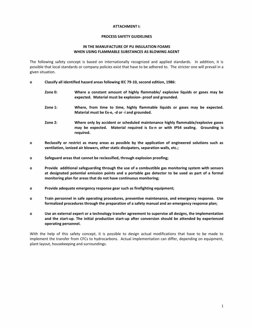
The following safety concept is based on internationally recognized and applied standards. In addition, it is possible that local standards or company policies exist that have to be adhered to. The stricter one will prevail in a given situation. o Classify all identified hazard areas following IEC 79-10, second edition, 1986:
Zone 0: Where a constant amount of highly flammable/ explosive liquids or gases may be expected. Material must be explosion- proof and grounded.
Zone 1: Where, from time to time, highly flammable liquids or gases may be expected.
Material must be Ex-e, -d or -i and grounded.
Zone 2: Where only by accident or scheduled maintenance highly flammable/explosive gases may be expected. Material required is Ex-n or with IP54 sealing. Grounding is required.
o Reclassify or restrict as many areas as possible by the application of engineered solutions such as
ventilation, ionized air blowers, other static dissipaters, separation walls, etc.; o Safeguard areas that cannot be reclassified, through explosion proofing; o Provide additional safeguarding through the use of a combustible gas monitoring system with sensors
at designated potential emission points and a portable gas detector to be used as part of a formal monitoring plan for areas that do not have continuous monitoring;
o Provide adequate emergency response gear such as firefighting equipment; o Train personnel in safe operating procedures, preventive maintenance, and emergency response. Use
formalized procedures through the preparation of a safety manual and an emergency response plan; o Use an external expert or a technology transfer agreement to supervise all designs, the implementation
and the start-up. The initial production start-up after conversion should be attended by experienced operating personnel.
With the help of this safety concept, it is possible to design actual modifications that have to be made to implement the transfer from CFCs to hydrocarbons. Actual implementation can differ, depending on equipment, plant layout, housekeeping and surroundings.
2
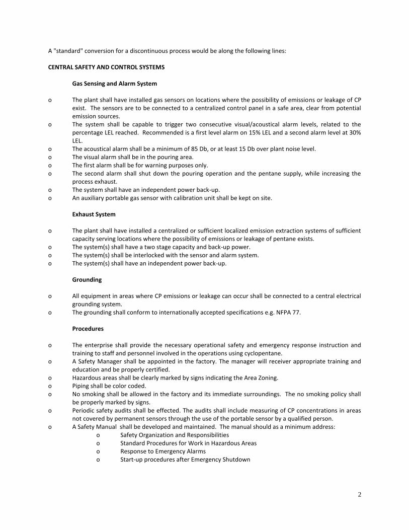
A "standard" conversion for a discontinuous process would be along the following lines: CENTRAL SAFETY AND CONTROL SYSTEMS
Gas Sensing and Alarm System
o The plant shall have installed gas sensors on locations where the possibility of emissions or leakage of CP
exist. The sensors are to be connected to a centralized control panel in a safe area, clear from potential emission sources.
o The system shall be capable to trigger two consecutive visual/acoustical alarm levels, related to the percentage LEL reached. Recommended is a first level alarm on 15% LEL and a second alarm level at 30% LEL.
o The acoustical alarm shall be a minimum of 85 Db, or at least 15 Db over plant noise level. o The visual alarm shall be in the pouring area. o The first alarm shall be for warning purposes only. o The second alarm shall shut down the pouring operation and the pentane supply, while increasing the
process exhaust. o The system shall have an independent power back-up. o An auxiliary portable gas sensor with calibration unit shall be kept on site.
Exhaust System
o The plant shall have installed a centralized or sufficient localized emission extraction systems of sufficient
capacity serving locations where the possibility of emissions or leakage of pentane exists. o The system(s) shall have a two stage capacity and back-up power. o The system(s) shall be interlocked with the sensor and alarm system. o The system(s) shall have an independent power back-up.
Grounding
o All equipment in areas where CP emissions or leakage can occur shall be connected to a central electrical
grounding system. o The grounding shall conform to internationally accepted specifications e.g. NFPA 77.
Procedures o The enterprise shall provide the necessary operational safety and emergency response instruction and
training to staff and personnel involved in the operations using cyclopentane. o A Safety Manager shall be appointed in the factory. The manager will receiver appropriate training and
education and be properly certified. o Hazardous areas shall be clearly marked by signs indicating the Area Zoning. o Piping shall be color coded. o No smoking shall be allowed in the factory and its immediate surroundings. The no smoking policy shall
be properly marked by signs. o Periodic safety audits shall be effected. The audits shall include measuring of CP concentrations in areas
not covered by permanent sensors through the use of the portable sensor by a qualified person. o A Safety Manual shall be developed and maintained. The manual should as a minimum address:
o Safety Organization and Responsibilities o Standard Procedures for Work in Hazardous Areas o Response to Emergency Alarms o Start-up procedures after Emergency Shutdown
3
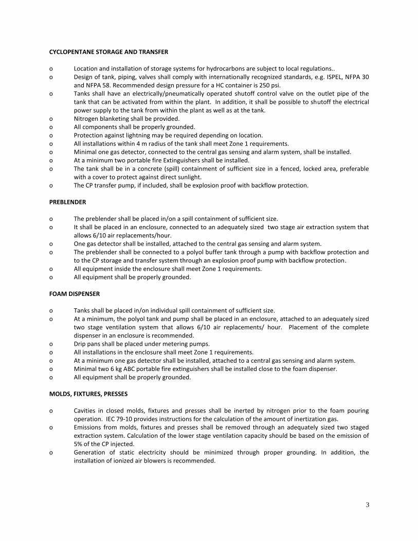
CYCLOPENTANE STORAGE AND TRANSFER o Location and installation of storage systems for hydrocarbons are subject to local regulations.. o Design of tank, piping, valves shall comply with internationally recognized standards, e.g. ISPEL, NFPA 30
and NFPA 58. Recommended design pressure for a HC container is 250 psi. o Tanks shall have an electrically/pneumatically operated shutoff control valve on the outlet pipe of the
tank that can be activated from within the plant. In addition, it shall be possible to shutoff the electrical power supply to the tank from within the plant as well as at the tank.
o Nitrogen blanketing shall be provided. o All components shall be properly grounded. o Protection against lightning may be required depending on location. o All installations within 4 m radius of the tank shall meet Zone 1 requirements. o Minimal one gas detector, connected to the central gas sensing and alarm system, shall be installed. o At a minimum two portable fire Extinguishers shall be installed. o The tank shall be in a concrete (spill) containment of sufficient size in a fenced, locked area, preferable
with a cover to protect against direct sunlight. o The CP transfer pump, if included, shall be explosion proof with backflow protection. PREBLENDER o The preblender shall be placed in/on a spill containment of sufficient size. o It shall be placed in an enclosure, connected to an adequately sized two stage air extraction system that
allows 6/10 air replacements/hour. o One gas detector shall be installed, attached to the central gas sensing and alarm system. o The preblender shall be connected to a polyol buffer tank through a pump with backflow protection and
to the CP storage and transfer system through an explosion proof pump with backflow protection. o All equipment inside the enclosure shall meet Zone 1 requirements. o All equipment shall be properly grounded. FOAM DISPENSER o Tanks shall be placed in/on individual spill containment of sufficient size. o At a minimum, the polyol tank and pump shall be placed in an enclosure, attached to an adequately sized
two stage ventilation system that allows 6/10 air replacements/ hour. Placement of the complete dispenser in an enclosure is recommended.
o Drip pans shall be placed under metering pumps. o All installations in the enclosure shall meet Zone 1 requirements. o At a minimum one gas detector shall be installed, attached to a central gas sensing and alarm system. o Minimal two 6 kg ABC portable fire extinguishers shall be installed close to the foam dispenser. o All equipment shall be properly grounded. MOLDS, FIXTURES, PRESSES o Cavities in closed molds, fixtures and presses shall be inerted by nitrogen prior to the foam pouring
operation. IEC 79-10 provides instructions for the calculation of the amount of inertization gas. o Emissions from molds, fixtures and presses shall be removed through an adequately sized two staged
extraction system. Calculation of the lower stage ventilation capacity should be based on the emission of 5% of the CP injected.
o Generation of static electricity should be minimized through proper grounding. In addition, the installation of ionized air blowers is recommended.
4
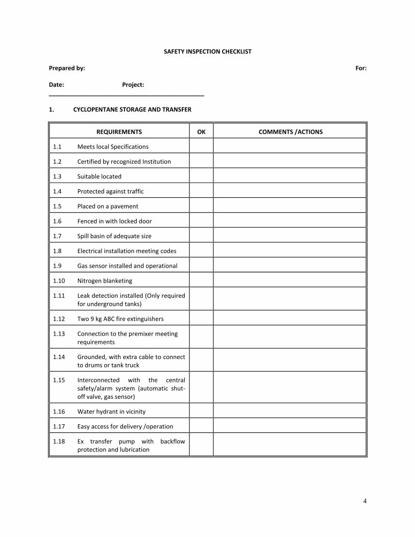
SAFETY INSPECTION CHECKLIST Prepared by: For: Date: Project: ______________________________________________ 1. CYCLOPENTANE STORAGE AND TRANSFER
REQUIREMENTS
OK
COMMENTS /ACTIONS
1.1 Meets local Specifications
1.2 Certified by recognized Institution
1.3 Suitable located
1.4 Protected against traffic
1.5 Placed on a pavement
1.6 Fenced in with locked door
1.7 Spill basin of adequate size
1.8 Electrical installation meeting codes
1.9 Gas sensor installed and operational
1.10 Nitrogen blanketing
1.11 Leak detection installed (Only required
for underground tanks)
1.12 Two 9 kg ABC fire extinguishers
1.13 Connection to the premixer meeting
requirements
1.14 Grounded, with extra cable to connect
to drums or tank truck
1.15 Interconnected with the central
safety/alarm system (automatic shut-off valve, gas sensor)
1.16 Water hydrant in vicinity
1.17 Easy access for delivery /operation
1.18 Ex transfer pump with backflow
protection and lubrication
5
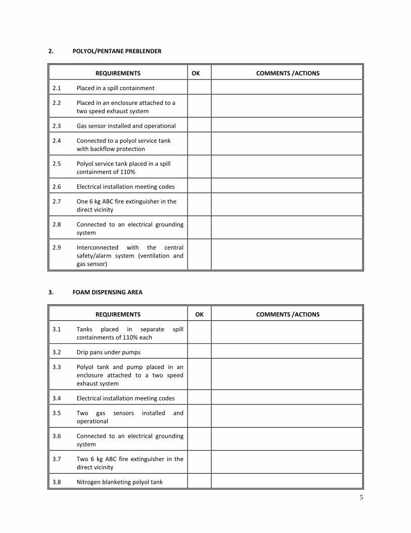
2. POLYOL/PENTANE PREBLENDER
REQUIREMENTS
OK
COMMENTS /ACTIONS
2.1 Placed in a spill containment
2.2 Placed in an enclosure attached to a
two speed exhaust system
2.3 Gas sensor installed and operational
2.4 Connected to a polyol service tank
with backflow protection
2.5 Polyol service tank placed in a spill
containment of 110%
2.6 Electrical installation meeting codes
2.7 One 6 kg ABC fire extinguisher in the
direct vicinity
2.8 Connected to an electrical grounding
system
2.9 Interconnected with the central
safety/alarm system (ventilation and gas sensor)
3. FOAM DISPENSING AREA
REQUIREMENTS
OK
COMMENTS /ACTIONS
3.1 Tanks placed in separate spill
containments of 110% each
3.2 Drip pans under pumps
3.3 Polyol tank and pump placed in an
enclosure attached to a two speed exhaust system
3.4 Electrical installation meeting codes
3.5 Two gas sensors installed and
operational
3.6 Connected to an electrical grounding
system
3.7 Two 6 kg ABC fire extinguisher in the
direct vicinity
3.8 Nitrogen blanketing polyol tank
6
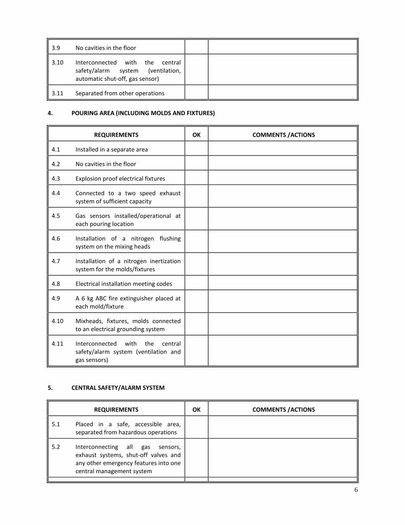
3.9 No cavities in the floor
3.10 Interconnected with the central
safety/alarm system (ventilation, automatic shut-off, gas sensor)
3.11 Separated from other operations
4. POURING AREA (INCLUDING MOLDS AND FIXTURES)
REQUIREMENTS
OK
COMMENTS /ACTIONS
4.1 Installed in a separate area
4.2 No cavities in the floor
4.3 Explosion proof electrical fixtures
4.4 Connected to a two speed exhaust
system of sufficient capacity
4.5 Gas sensors installed/operational at
each pouring location
4.6 Installation of a nitrogen flushing
system on the mixing heads
4.7 Installation of a nitrogen inertization
system for the molds/fixtures
4.8 Electrical installation meeting codes
4.9 A 6 kg ABC fire extinguisher placed at
each mold/fixture
4.10 Mixheads, fixtures, molds connected
to an electrical grounding system
4.11 Interconnected with the central
safety/alarm system (ventilation and gas sensors)
5. CENTRAL SAFETY/ALARM SYSTEM
REQUIREMENTS
OK
COMMENTS /ACTIONS
5.1 Placed in a safe, accessible area,
separated from hazardous operations
5.2 Interconnecting all gas sensors,
exhaust systems, shut-off valves and any other emergency features into one central management system
7
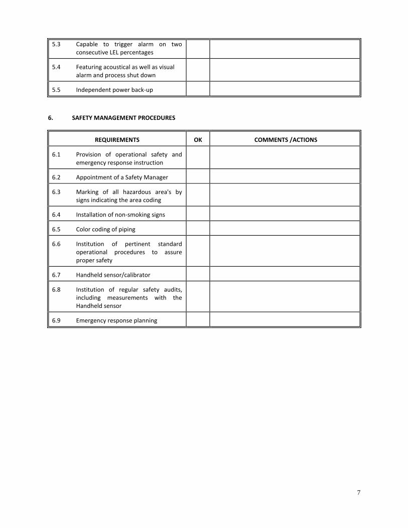
5.3 Capable to trigger alarm on two consecutive LEL percentages
5.4 Featuring acoustical as well as visual
alarm and process shut down
5.5 Independent power back-up
6. SAFETY MANAGEMENT PROCEDURES
REQUIREMENTS
OK
COMMENTS /ACTIONS
6.1 Provision of operational safety and
emergency response instruction
6.2 Appointment of a Safety Manager
6.3 Marking of all hazardous area's by
signs indicating the area coding
6.4 Installation of non-smoking signs
6.5 Color coding of piping
6.6 Institution of pertinent standard
operational procedures to assure proper safety
6.7 Handheld sensor/calibrator
6.8 Institution of regular safety audits,
including measurements with the Handheld sensor
6.9 Emergency response planning
HCFC Phaseout Technologies in PU Foams 8
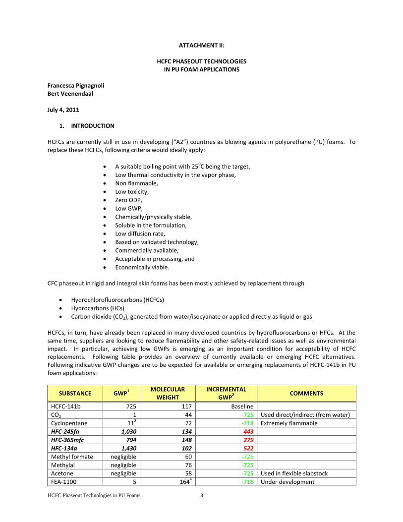
ATTACHMENT II:
HCFC PHASEOUT TECHNOLOGIES
IN PU FOAM APPLICATIONS Francesca Pignagnoli Bert Veenendaal July 4, 2011
1. INTRODUCTION
HCFCs are currently still in use in developing (“A2”) countries as blowing agents in polyurethane (PU) foams. To replace these HCFCs, following criteria would ideally apply:
A suitable boiling point with 250C being the target,
Low thermal conductivity in the vapor phase,
Non flammable,
Low toxicity,
Zero ODP,
Low GWP,
Chemically/physically stable,
Soluble in the formulation,
Low diffusion rate,
Based on validated technology,
Commercially available,
Acceptable in processing, and
Economically viable.
CFC phaseout in rigid and integral skin foams has been mostly achieved by replacement through
Hydrochlorofluorocarbons (HCFCs)
Hydrocarbons (HCs)
Carbon dioxide (CO2), generated from water/isocyanate or applied directly as liquid or gas HCFCs, in turn, have already been replaced in many developed countries by hydrofluorocarbons or HFCs. At the same time, suppliers are looking to reduce flammability and other safety-related issues as well as environmental impact. In particular, achieving low GWPs is emerging as an important condition for acceptability of HCFC replacements. Following table provides an overview of currently available or emerging HCFC alternatives. Following indicative GWP changes are to be expected for available or emerging replacements of HCFC-141b in PU foam applications:
SUBSTANCE GWP1
MOLECULAR WEIGHT
INCREMENTAL GWP
2 COMMENTS
HCFC-141b 725 117 Baseline
CO2 1 44 -725 Used direct/indirect (from water)
Cyclopentane 112 72 -718 Extremely flammable
HFC-245fa 1,030 134 443
HFC-365mfc 794 148 279
HFC-134a 1,430 102 522
Methyl formate negligible
60 -725
Methylal negligible 76 -725
Acetone negligible 58 -725 Used in flexible slabstock
FEA-1100
5 1644 -718 Under development
HCFC Phaseout Technologies in PU Foams 9
HFO-1234ze 6 114 -719 Recently introduced
HBA-2 <15 <134 >-708 Under development
AFA-L1 <15 <134 >-708 Under development 1
Unless otherwise indicated, taken from IPCC’s Fourth Assessment (2007) 2 Derived from comparing GWPs compared to the baseline on an equimolar base. It should be noted that in
practice formulators may make changes such as increased water or ABA blends that impact the global warming effect 3
From UNEP Foams Technical Options Committee’s 2006 report 4 Calculated from published formulations
Green = beneficial GWP effect; red = unfavorable GWP effect
These technologies are described in more detail below. It should be pointed out that a comparison between GWP is an approximation of the climate effect. A full lifecycle determination or a functional unit approach (as described by the MLF Secretariat in it paper 55/47) which includes energy efficiency and other factors is a better—but more lengthy —approach.
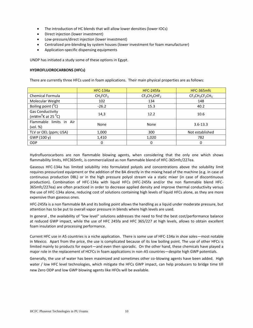
1. PROVEN ZERO ODP TECHNOLOGIES HYDROCARBONS Pentane isomers are the most utilized hydrocarbon blowing agents (Bas). Their main physical properties are as follows:
normal-pentane
iso-pentane cyclo-pentane
Chemical Formula C5H
12 C
5H
12 C
5H
10
Molecular Weight 72 72 70
Boiling point (0C) 36 28 50
Gas Conductivity (mWm
0K at 25
0C)
14,6 13,8 12,0
Flammable limits in Air (vol. %)
1.4-8.3 1.4-8.3 1.4-8.3
GWP (100 y) 11 11 11
ODP 0 0 0
Hydrocarbons are Zero ODP/Low GWP flammable blowing agents and are a preferred solution for those producers who can afford the investment for managing safe handling of flammable formulations. Evolution of hydrocarbon formulations has come to the point that systems can meet fire behavior requirements despite the flammability of the BA. Among the different isomers available, n-pentane or the commercial blends of n-pentane and iso-pentane are the most cost effective ones and are used in construction application, mainly through continuous production process. On the other hand, c-pentane is more soluble than n-pentane or iso-pentane and features the lowest thermal conductivity within the family of isomers. Because of this, it is a preferred choice for those applications where thermal conductivity is a key property, for instance domestic appliance and commercial refrigeration industry. Fine tuning of properties has taken place as well through blends (like cyclo-pentane/isopentane or cyclo-pentane/iso-butane, where iso-butane is a gaseous molecule with limited solubility, its use is not wide-spread). There have been many HC-based/MLF-supported CFC-phaseout projects in refrigeration and in panel applications. The technology, however, was deemed unsafe for applications such as spray and in situ foams (“PIP”). Despite that these blowing agents are low cost molecules, the investment costs to handle their flammability aspects are the same as at the time of phasing out CFCs and the technology will continue to be too expensive for SMEs and restricted in principle to the same applications as before. However, there are options to fine-tune project costs and investigate other applications:
HCFC Phaseout Technologies in PU Foams 10
The introduction of HC blends that will allow lower densities (lower IOCs)
Direct injection (lower investment)
Low-pressure/direct injection (lower investment)
Centralized pre-blending by system houses (lower investment for foam manufacturer)
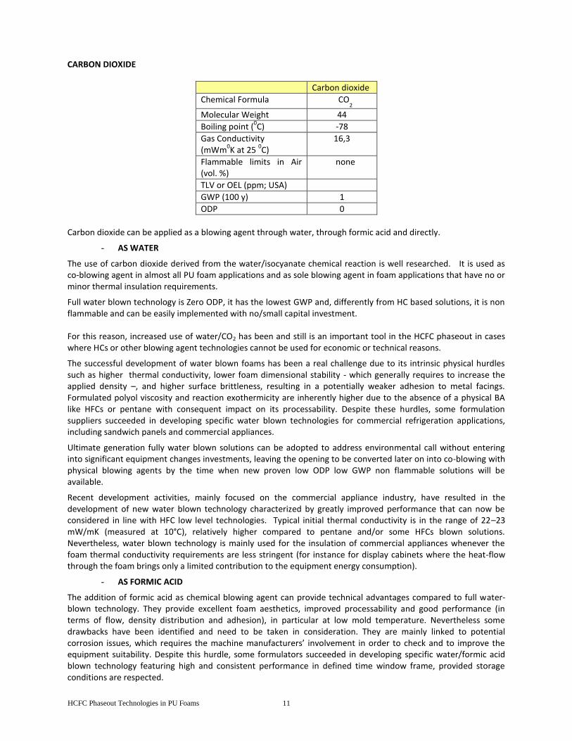
Application-specific dispensing equipments UNDP has initiated a study some of these options in Egypt. HYDROFLUOROCARBONS (HFCs) There are currently three HFCs used in foam applications. Their main physical properties are as follows:
HFC-134a HFC-245fa HFC-365mfc
Chemical Formula CH2FCF3 CF3CH2CHF2 CF3CH2CF2CH3
Molecular Weight 102 134 148
Boiling point (0C) -26.2 15.3 40.2
Gas Conductivity (mWm
0K at 25
0C)
14,3 12.2 10.6
Flammable limits in Air (vol. %)
None None 3.6-13.3
TLV or OEL (ppm; USA) 1,000 300 Not established
GWP (100 y) 1,410 1,020 782
ODP 0 0 0
Hydrofluorocarbons are non flammable blowing agents, when considering that the only one which shows flammability limits, HFC365mfc, is commercialized as non flammable blend of HFC-365mfc/227ea.
Gaseous HFC-134a has limited solubility into formulated polyols and concentrations above the solubility limit requires pressurized equipment or the addition of the BA directly in the mixing head of the machine (e.g. in case of continuous production DBL) or in the high pressure polyol stream via a static mixer (in case of discontinuous production). Combination of HFC-134a with liquid HFCs (HFC-245fa and/or the non flammable blend HFC-365mfc/227ea) are often practiced in order to decrease applied density and improve thermal conductivity versus the use of HFC-134a alone, reducing cost of solutions containing high levels of liquid HFCs alone, as they are more expensive than gaseous ones.
HFC-245fa is a non flammable BA and its boiling point allows the handling as a liquid under moderate pressure, but attention has to be put to overall vapor pressure in blends where high levels are used.
In general , the availability of "low level" solutions addresses the need to find the best cost/performance balance at reduced GWP impact, while the use of HFC 245fa and HFC 365/227 at high levels, allows to obtain excellent foam insulation and processing performance. Current HFC use in A5 countries is a niche application. There is some use of HFC-134a in shoe soles—most notable in Mexico. Apart from the price, the use is complicated because of its low boiling point. The use of other HFCs is limited mainly to products for export—and even then sporadic. On the other hand, these chemicals have played a major role in the replacement of HCFCs in foam applications in non-A5 countries—despite high GWP potentials.
Generally, the use of water has been maximized and sometimes other co-blowing agents have been added. High
water / low HFC level technologies, which mitigate the HFCs GWP impact, can help producers to bridge time till
new Zero ODP and low GWP blowing agents like HFOs will be available.
HCFC Phaseout Technologies in PU Foams 11
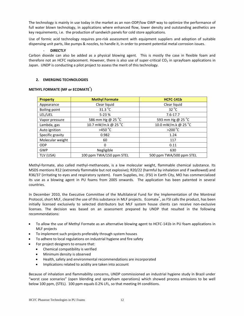
CARBON DIOXIDE
Carbon dioxide
Chemical Formula CO2
Molecular Weight 44
Boiling point (0C) -78
Gas Conductivity (mWm
0K at 25
0C)
16,3
Flammable limits in Air (vol. %)
none
TLV or OEL (ppm; USA)
GWP (100 y) 1
ODP 0
Carbon dioxide can be applied as a blowing agent through water, through formic acid and directly.
- AS WATER
The use of carbon dioxide derived from the water/isocyanate chemical reaction is well researched. It is used as co-blowing agent in almost all PU foam applications and as sole blowing agent in foam applications that have no or minor thermal insulation requirements.
Full water blown technology is Zero ODP, it has the lowest GWP and, differently from HC based solutions, it is non flammable and can be easily implemented with no/small capital investment. For this reason, increased use of water/CO2 has been and still is an important tool in the HCFC phaseout in cases where HCs or other blowing agent technologies cannot be used for economic or technical reasons.
The successful development of water blown foams has been a real challenge due to its intrinsic physical hurdles such as higher thermal conductivity, lower foam dimensional stability - which generally requires to increase the applied density –, and higher surface brittleness, resulting in a potentially weaker adhesion to metal facings. Formulated polyol viscosity and reaction exothermicity are inherently higher due to the absence of a physical BA like HFCs or pentane with consequent impact on its processability. Despite these hurdles, some formulation suppliers succeeded in developing specific water blown technologies for commercial refrigeration applications, including sandwich panels and commercial appliances.
Ultimate generation fully water blown solutions can be adopted to address environmental call without entering into significant equipment changes investments, leaving the opening to be converted later on into co-blowing with physical blowing agents by the time when new proven low ODP low GWP non flammable solutions will be available.
Recent development activities, mainly focused on the commercial appliance industry, have resulted in the development of new water blown technology characterized by greatly improved performance that can now be considered in line with HFC low level technologies. Typical initial thermal conductivity is in the range of 22–23 mW/mK (measured at 10°C), relatively higher compared to pentane and/or some HFCs blown solutions. Nevertheless, water blown technology is mainly used for the insulation of commercial appliances whenever the foam thermal conductivity requirements are less stringent (for instance for display cabinets where the heat-flow through the foam brings only a limited contribution to the equipment energy consumption).
- AS FORMIC ACID
The addition of formic acid as chemical blowing agent can provide technical advantages compared to full water-blown technology. They provide excellent foam aesthetics, improved processability and good performance (in terms of flow, density distribution and adhesion), in particular at low mold temperature. Nevertheless some drawbacks have been identified and need to be taken in consideration. They are mainly linked to potential corrosion issues, which requires the machine manufacturers’ involvement in order to check and to improve the equipment suitability. Despite this hurdle, some formulators succeeded in developing specific water/formic acid blown technology featuring high and consistent performance in defined time window frame, provided storage conditions are respected.
HCFC Phaseout Technologies in PU Foams 12
The technology is mainly in use today in the market as an non-ODP/low GWP way to optimize the performance of full water blown technology, in applications where enhanced flow, lower density and outstanding aesthetics are key requirements, i.e. the production of sandwich panels for cold store applications.
Use of formic acid technology requires pre-risk assessment with equipment suppliers and adoption of suitable dispensing unit parts, like pumps & nozzles, to handle it, in order to prevent potential metal corrosion issues.
- DIRECTLY Carbon dioxide can also be added as a physical blowing agent. This is mostly the case in flexible foam and therefore not an HCFC replacement. However, there is also use of super-critical CO2 in sprayfoam applications in Japan. UNDP is conducting a pilot project to assess the merit of this technology.
2. EMERGING TECHNOLOGIES METHYL FORMATE (MF or ECOMATE
®)
Property Methyl Formate HCFC-141b
Appearance Clear liquid Clear liquid
Boiling point 31.3 oC 32
oC
LEL/UEL 5-23 % 7.6-17.7
Vapor pressure 586 mm Hg @ 25 oC 593 mm Hg @ 25
oC
Lambda, gas 10.7 mW/m.k @ 25 oC 10.0 mW/m.k @ 25
oC
Auto ignition >450 oC >200
oC
Specific gravity 0.982 1.24
Molecular weight 60 117
ODP 0 0.11
GWP Negligible 630
TLV (USA) 100 ppm TWA/150 ppm STEL 500 ppm TWA/500 ppm STEL
Methyl-formate, also called methyl-methanoate, is a low molecular weight, flammable chemical substance. Its MSDS mentions R12 (extremely flammable but not explosive); R20/22 (harmful by inhalation and if swallowed) and R36/37 (irritating to eyes and respiratory system). Foam Supplies, Inc. (FSI) in Earth City, MO has commercialized its use as a blowing agent in PU foams from 2005 onwards. The application has been patented in several countries. In December 2010, the Executive Committee of the Multilateral Fund for the Implementation of the Montreal Protocol, short MLF, cleared the use of this substance in MLF projects. Ecomate
®, as FSI calls the product, has been
initially licensed exclusively to selected distributors but MLF system house clients can receive non-exclusive licenses. The decision was based on an assessment prepared by UNDP that resulted in the following recommendations:
To allow the use of Methyl Formate as an alternative blowing agent to HCFC-141b in PU foam applications in MLF projects
To implement such projects preferably through system houses
To adhere to local regulations on industrial hygiene and fire safety
For project designers to ensure that:
Chemical compatibility is verified
Minimum density is observed
Health, safety and environmental recommendations are incorporated
Implications related to acidity are taken into account Because of inhalation and flammability concerns, UNDP commissioned an industrial hygiene study in Brazil under “worst case scenarios” (open blending and sprayfoam operations) which showed process emissions to be well below 100 ppm, (STEL). 100 ppm equals 0.2% LFL, so that meeting IH conditions.
HCFC Phaseout Technologies in PU Foams 13
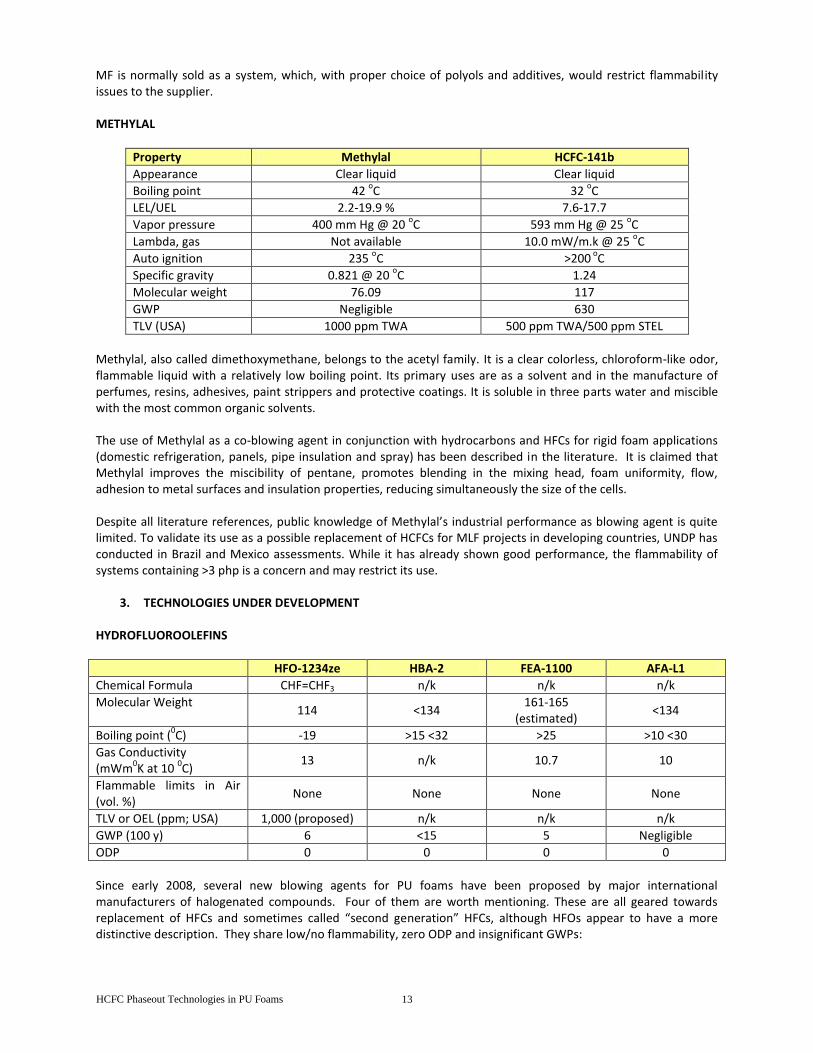
MF is normally sold as a system, which, with proper choice of polyols and additives, would restrict flammability issues to the supplier. METHYLAL
Property Methylal HCFC-141b
Appearance Clear liquid Clear liquid
Boiling point 42 oC 32
oC
LEL/UEL 2.2-19.9 % 7.6-17.7
Vapor pressure 400 mm Hg @ 20 oC 593 mm Hg @ 25
oC
Lambda, gas Not available 10.0 mW/m.k @ 25 oC
Auto ignition 235 oC >200
oC
Specific gravity 0.821 @ 20 oC 1.24
Molecular weight 76.09 117
GWP Negligible 630
TLV (USA) 1000 ppm TWA 500 ppm TWA/500 ppm STEL
Methylal, also called dimethoxymethane, belongs to the acetyl family. It is a clear colorless, chloroform-like odor, flammable liquid with a relatively low boiling point. Its primary uses are as a solvent and in the manufacture of perfumes, resins, adhesives, paint strippers and protective coatings. It is soluble in three parts water and miscible with the most common organic solvents. The use of Methylal as a co-blowing agent in conjunction with hydrocarbons and HFCs for rigid foam applications (domestic refrigeration, panels, pipe insulation and spray) has been described in the literature. It is claimed that Methylal improves the miscibility of pentane, promotes blending in the mixing head, foam uniformity, flow, adhesion to metal surfaces and insulation properties, reducing simultaneously the size of the cells. Despite all literature references, public knowledge of Methylal’s industrial performance as blowing agent is quite limited. To validate its use as a possible replacement of HCFCs for MLF projects in developing countries, UNDP has conducted in Brazil and Mexico assessments. While it has already shown good performance, the flammability of systems containing >3 php is a concern and may restrict its use.
3. TECHNOLOGIES UNDER DEVELOPMENT
HYDROFLUOROOLEFINS
HFO-1234ze HBA-2 FEA-1100 AFA-L1
Chemical Formula CHF=CHF3 n/k n/k n/k
Molecular Weight 114 <134
161-165 (estimated)
<134
Boiling point (0C) -19 >15 <32 >25 >10 <30
Gas Conductivity (mWm
0K at 10
0C)
13 n/k 10.7 10
Flammable limits in Air (vol. %)
None None None None
TLV or OEL (ppm; USA) 1,000 (proposed) n/k n/k n/k
GWP (100 y) 6 <15 5 Negligible
ODP 0 0 0 0
Since early 2008, several new blowing agents for PU foams have been proposed by major international manufacturers of halogenated compounds. Four of them are worth mentioning. These are all geared towards replacement of HFCs and sometimes called “second generation” HFCs, although HFOs appear to have a more distinctive description. They share low/no flammability, zero ODP and insignificant GWPs:
HCFC Phaseout Technologies in PU Foams 14
Except HFO-1234ze, all other chemicals listed out in the table above will not be commercialized in the next few years and, most likely, will then first be geared towards developed countries where legal limitations on HFCs are considered. It may appear somewhat late in an A5 context where foam conversion is prioritized. As to HFO-1234ze, this is already in use as a replacement of HFC-134a in one component foams (OCF). There are only few OCF manufacturers in developing countries.
HC Pilot project Egypt Submitted May 11, 2009
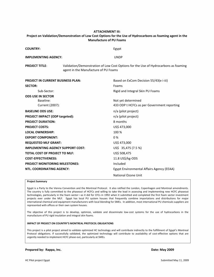
ATTACHEMENT III:
Project on Validation/Demonstration of Low Cost Options for the Use of Hydrocarbons as foaming agent in the Manufacture of PU Foams
COUNTRY: Egypt IMPLEMENTING AGENCY: UNDP PROJECT TITLE: Validation/Demonstration of Low Cost Options for the Use of Hydrocarbons as foaming
agent in the Manufacture of PU Foams
PROJECT IN CURRENT BUSINESS PLAN: Based on ExCom Decision 55/43(e i-iii)
SECTOR: Foams
Sub-Sector: Rigid and Integral Skin PU Foams
ODS USE IN SECTOR Baseline: Not yet determined
Current (2007): 433 ODP t HCFCs as per Government reporting
BASELINE ODS USE: n/a (pilot project)
PROJECT IMPACT (ODP targeted): n/a (pilot project)
PROJECT DURATION: 8 months
PROJECT COSTS: US$ 473,000
LOCAL OWNERSHIP: 100 %
EXPORT COMPONENT: 0 %
REQUESTED MLF GRANT: US$ 473,000
IMPLEMENTING AGENCY SUPPORT COST: US$ 35,475 (7.5 %)
TOTAL COST OF PROJECT TO MLF: US$ 508,475
COST-EFFECTIVENESS: 11.8 US$/kg-ODS
PROJECT MONITORING MILESTONES: Included
NTL. COORDINATING AGENCY: Egypt Environmental Affairs Agency (EEAA)
National Ozone Unit
Project Summary Egypt is a Party to the Vienna Convention and the Montreal Protocol. It also ratified the London, Copenhagen and Montreal amendments. The country is fully committed to the phaseout of HCFCs and willing to take the lead in assessing and implementing new HCFC phaseout technologies, particularly in the foam sector—as it did for CFCs in 1992 when it submitted and completed the first foam sector investment projects ever under the MLF. Egypt has local PU system houses that frequently combine importations and distributions for major international chemical and equipment manufacturers with local blending for SMEs. In addition, most international PU chemicals suppliers are represented with offices or their own system houses. The objective of this project is to develop, optimize, validate and disseminate low-cost systems for the use of hydrocarbons in the manufacture of PU rigid insulation and integral skin foams.
IMPACT OF PROJECT ON COUNTRY’S MONTREAL PROTOCOL OBLIGATIONS This project is a pilot project aimed to validate optimized HC technology and will contribute indirectly to the fulfillment of Egypt’s Montreal Protocol obligations. If successfully validated, the optimized technology will contribute to availability of cost-effective options that are urgently needed to implement HCFC phase-out, particularly at SMEs.
Prepared by: Rappa, Inc. Date: May 2009
HC Pilot project Egypt Submitted May 11, 2009
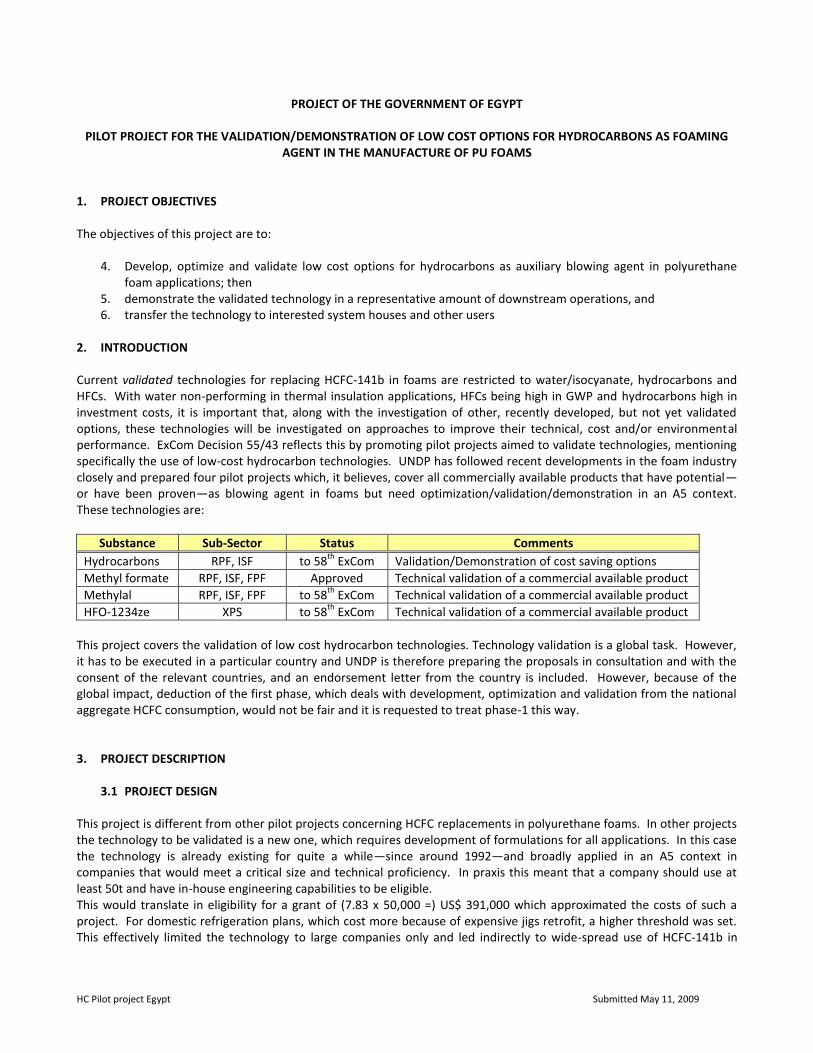
PROJECT OF THE GOVERNMENT OF EGYPT
PILOT PROJECT FOR THE VALIDATION/DEMONSTRATION OF LOW COST OPTIONS FOR HYDROCARBONS AS FOAMING AGENT IN THE MANUFACTURE OF PU FOAMS
1. PROJECT OBJECTIVES The objectives of this project are to:
4. Develop, optimize and validate low cost options for hydrocarbons as auxiliary blowing agent in polyurethane foam applications; then
5. demonstrate the validated technology in a representative amount of downstream operations, and 6. transfer the technology to interested system houses and other users
2. INTRODUCTION Current validated technologies for replacing HCFC-141b in foams are restricted to water/isocyanate, hydrocarbons and HFCs. With water non-performing in thermal insulation applications, HFCs being high in GWP and hydrocarbons high in investment costs, it is important that, along with the investigation of other, recently developed, but not yet validated options, these technologies will be investigated on approaches to improve their technical, cost and/or environmental performance. ExCom Decision 55/43 reflects this by promoting pilot projects aimed to validate technologies, mentioning specifically the use of low-cost hydrocarbon technologies. UNDP has followed recent developments in the foam industry closely and prepared four pilot projects which, it believes, cover all commercially available products that have potential—or have been proven—as blowing agent in foams but need optimization/validation/demonstration in an A5 context. These technologies are:
Substance Sub-Sector Status Comments
Hydrocarbons RPF, ISF to 58th
ExCom Validation/Demonstration of cost saving options
Methyl formate RPF, ISF, FPF Approved Technical validation of a commercial available product
Methylal RPF, ISF, FPF to 58th
ExCom Technical validation of a commercial available product
HFO-1234ze XPS to 58th
ExCom Technical validation of a commercial available product
This project covers the validation of low cost hydrocarbon technologies. Technology validation is a global task. However, it has to be executed in a particular country and UNDP is therefore preparing the proposals in consultation and with the consent of the relevant countries, and an endorsement letter from the country is included. However, because of the global impact, deduction of the first phase, which deals with development, optimization and validation from the national aggregate HCFC consumption, would not be fair and it is requested to treat phase-1 this way. 3. PROJECT DESCRIPTION 3.1 PROJECT DESIGN This project is different from other pilot projects concerning HCFC replacements in polyurethane foams. In other projects the technology to be validated is a new one, which requires development of formulations for all applications. In this case the technology is already existing for quite a while—since around 1992—and broadly applied in an A5 context in companies that would meet a critical size and technical proficiency. In praxis this meant that a company should use at least 50t and have in-house engineering capabilities to be eligible. This would translate in eligibility for a grant of (7.83 x 50,000 =) US$ 391,000 which approximated the costs of such a project. For domestic refrigeration plans, which cost more because of expensive jigs retrofit, a higher threshold was set. This effectively limited the technology to large companies only and led indirectly to wide-spread use of HCFC-141b in
SMEs. Therefore, if the cost of hydrocarbon technology is not lowered, SMEs can only hope to fall back on environmentally undesirable HFCs, low performing and expensive water-based systems or hope that the Validation/Demonstration of new technologies—will provide more satisfactory options. The use of hydrocarbon technology has not materially changed over the last 17 years. It requires costly pre-blending equipment, an explosion-free area and special safety procedures. Also, in many countries the systems are unchanged while in Europe significant system optimization has taken place (additives, special polyols, co-blending). UNDP sees options for cost reductions in three areas:
preblending at supplier level would delete the need for a preblender plus auxiliaries—but cause some increase in the system price;
direct injection of hydrocarbons would also remove the need for a preblender but increase the equipment cost somewhat;
the introduction of modern HC blends would allow for lower densities—along with the above-mentioned options and also lower in this way the current operating costs.
To test the feasibility of these concepts, the development and commercialization of stable pre-blends that can be safely transported and three-component production equipment is required, in addition to the introduction of modern HC blends.
This project is designed in four steps:
4. development, optimization and Validation/Demonstration of premixed, stabilized, modern hydrocarbons systems that can be used directly by foam manufacturers (which means that the blowing agent is incorporated) or used together with direct injection of the blowing agent
5. development of a three component foam dispenser, capable to direct inject hydrocarbons (pentane of cyclopentane blends)
6. placement of the three-component dispenser at a foam manufacturer followed by trials with a. direct injection of the blowing agent b. using a fully preblended polyol system
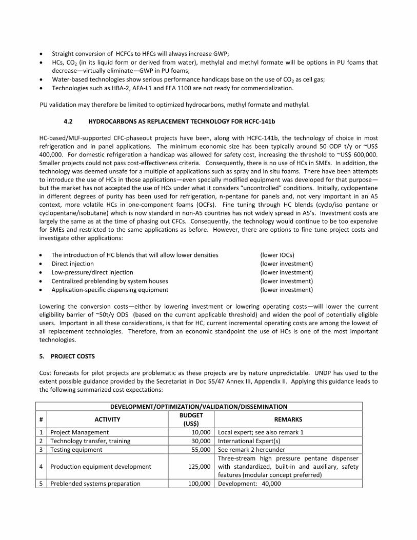
4. demonstration of the technology followed by dissemination through an inter-regional workshop Other PU pilot projects carry a second phase to demonstrate commercial application and include the use of a supplier to develop the necessary systems. There is no need for this in this project. The system part will be an optimization based on knowledge that is already available in Europe and incremental success is virtually assured. Building a three component foaming unit has been before applied in an MLF project through a retrofit so, in this case it will be more of a design optimization than application of a new concept. Also, there is no need to demonstrate the two technology versions in all foam applications. The variations in required formulations are well known to the chemical suppliers that cater HC systems. Companies do not conduct regular testing on properties of their foams, nor do they set standards. The determination of baseline data on critical properties is a precondition for a successful Validation/Demonstration program. In this case, the supplier of the system will conduct the product testing. As hydrocarbons are “highly flammable”, UNDP considers the process at the system house (blending) AND at user level (processing) hazardous and requiring adequate safeguards. Current safety requirements are described in UNEP/OzL.Pro/ExCom/25/54 (Annex 2). UNDP requires an independent safety audit to be conducted prior to commercial operation of a converted plant (Annex 3). Emission monitoring will have to be conducted and, based the outcome modifications/simplifications of the safety requirements can be proposed. PROJECT IMPLEMENTATION The project will be implemented through four steps. Following concrete actions are planned:
7. System Development: UNDP will contract this out following standard procurement procedures to a qualified chemical supplier (competitive bidding).
8. Equipment Development: as before, UNDP will contract this out to a qualified equipment supplier, following
standard procurement procedures.
9. Trials at a Foam Plant: A company that is willing to conduct an early phaseout project based on the use of hydrocarbons will be selected as a part of the foam industry survey. The company should have an ODS consumption of around 40 t and have reasonable in-house technical capabilities. 4-5 candidates fit the requirements in Egypt, but here again the Government requested UNDP to select the company through bidding.
10. Validation: This will include emission/worker exposure monitoring, design of a safety system and safety
procedures, validation of the outcome of the project and holding of an information dissemination inter-regional workshop. These tasks are assigned as follows:
a. Monitoring - EEAA b. Safety design - EEAA/UNDP c. Validation - UNEP Foams Technical Options Committee (FTOC) d. Workshop - EEAA/UNDP
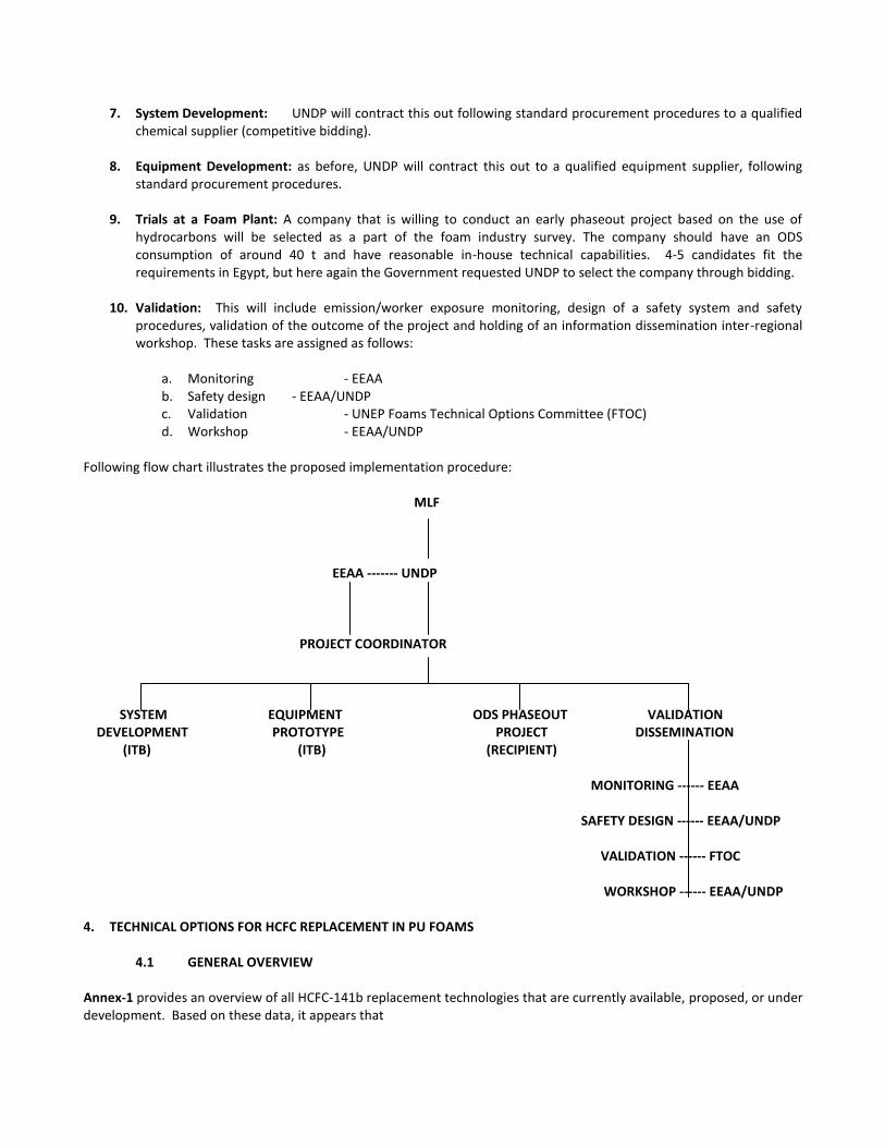
Following flow chart illustrates the proposed implementation procedure: MLF
EEAA ------- UNDP PROJECT COORDINATOR
SYSTEM EQUIPMENT ODS PHASEOUT VALIDATION DEVELOPMENT PROTOTYPE PROJECT DISSEMINATION (ITB) (ITB) (RECIPIENT) MONITORING ------ EEAA SAFETY DESIGN ------ EEAA/UNDP VALIDATION ------ FTOC WORKSHOP ------ EEAA/UNDP 4. TECHNICAL OPTIONS FOR HCFC REPLACEMENT IN PU FOAMS
4.1 GENERAL OVERVIEW
Annex-1 provides an overview of all HCFC-141b replacement technologies that are currently available, proposed, or under development. Based on these data, it appears that
Straight conversion of HCFCs to HFCs will always increase GWP;
HCs, CO2 (in its liquid form or derived from water), methylal and methyl formate will be options in PU foams that decrease—virtually eliminate—GWP in PU foams;
Water-based technologies show serious performance handicaps base on the use of CO2 as cell gas;
Technologies such as HBA-2, AFA-L1 and FEA 1100 are not ready for commercialization. PU validation may therefore be limited to optimized hydrocarbons, methyl formate and methylal. 4.2 HYDROCARBONS AS REPLACEMENT TECHNOLOGY FOR HCFC-141b
HC-based/MLF-supported CFC-phaseout projects have been, along with HCFC-141b, the technology of choice in most refrigeration and in panel applications. The minimum economic size has been typically around 50 ODP t/y or ~US$ 400,000. For domestic refrigeration a handicap was allowed for safety cost, increasing the threshold to ~US$ 600,000. Smaller projects could not pass cost-effectiveness criteria. Consequently, there is no use of HCs in SMEs. In addition, the technology was deemed unsafe for a multiple of applications such as spray and in situ foams. There have been attempts to introduce the use of HCs in those applications—even specially modified equipment was developed for that purpose—but the market has not accepted the use of HCs under what it considers “uncontrolled” conditions. Initially, cyclopentane in different degrees of purity has been used for refrigeration, n-pentane for panels and, not very important in an A5 context, more volatile HCs in one-component foams (OCFs). Fine tuning through HC blends (cyclo/iso pentane or cyclopentane/isobutane) which is now standard in non-A5 countries has not widely spread in A5’s. Investment costs are largely the same as at the time of phasing out CFCs. Consequently, the technology would continue to be too expensive for SMEs and restricted to the same applications as before. However, there are options to fine-tune project costs and investigate other applications:
The introduction of HC blends that will allow lower densities (lower IOCs)
Direct injection (lower investment)
Low-pressure/direct injection (lower investment)
Centralized preblending by system houses (lower investment)
Application-specific dispensing equipment (lower investment) Lowering the conversion costs—either by lowering investment or lowering operating costs—will lower the current eligibility barrier of ~50t/y ODS (based on the current applicable threshold) and widen the pool of potentially eligible users. Important in all these considerations, is that for HC, current incremental operating costs are among the lowest of all replacement technologies. Therefore, from an economic standpoint the use of HCs is one of the most important technologies. 5. PROJECT COSTS Cost forecasts for pilot projects are problematic as these projects are by nature unpredictable. UNDP has used to the extent possible guidance provided by the Secretariat in Doc 55/47 Annex III, Appendix II. Applying this guidance leads to the following summarized cost expectations:
DEVELOPMENT/OPTIMIZATION/VALIDATION/DISSEMINATION
# ACTIVITY BUDGET
(US$) REMARKS
1 Project Management 10,000 Local expert; see also remark 1
2 Technology transfer, training 30,000 International Expert(s)
3 Testing equipment 55,000 See remark 2 hereunder
4 Production equipment development 125,000 Three-stream high pressure pentane dispenser with standardized, built-in and auxiliary, safety features (modular concept preferred)
5 Preblended systems preparation 100,000 Development: 40,000
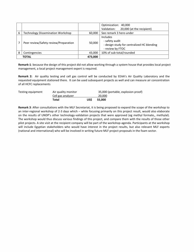
Optimization: 40,000 Validation: 20,000 (at the recipient)
6 Technology Dissemination Workshop 60,000 See remark 3 here-under
7 Peer review/Safety review/Preparation 50,000
Includes - safety audit - design study for centralized HC blending - review by FTOC
8 Contingencies 43,000 10% of sub-total/rounded
TOTAL 473,000
Remark-1: because the design of this project did not allow working through a system house that provides local project management, a local project management expert is required. Remark 2: Air quality testing and cell gas control will be conducted by EEAA’s Air Quality Laboratory and the requested equipment stationed there. It can be used subsequent projects as well and can measure air concentration of all HCFC replacements Testing equipment Air quality monitor 35,000 (portable, explosion proof) Cell gas analyzer 20,000 Total US$ 55,000 Remark 3: After consultations with the MLF Secretariat, it is being proposed to expand the scope of the workshop to an inter-regional workshop of 2-3 days which – while focusing primarily on this project result, would also elaborate on the results of UNDP’s other technology-validation projects that were approved (eg methyl formate,, methylal). The workshop would thus discuss various findings of this project, and compare them with the results of those other pilot projects. A site visit at the recipient company will be part of the workshop-agenda. Participants at the workshop will include Egyptian stakeholders who would have interest in the project results, but also relevant MLF experts (national and international) who will be involved in writing future MLF project proposals in the foam sector.
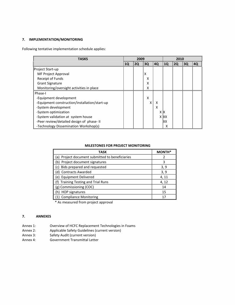
7. IMPLEMENTATION/MONITORING Following tentative implementation schedule applies:
TASKS 2009 2010
1Q 2Q 3Q 4Q 1Q 2Q 3Q 4Q
Project Start-up MF Project Approval Receipt of Funds Grant Signature Monitoring/oversight activities in place
X X X X
Phase-I -Equipment development -Equipment construction/installation/start-up -System development -System optimization -System validation at system house -Peer review/detailed design of phase- II -Technology Dissemination Workshop(s)
X X
X X X X
X XX XX X
MILESTONES FOR PROJECT MONITORING
TASK MONTH*
(a) Project document submitted to beneficiaries 2
(b) Project document signatures 3
(c) Bids prepared and requested 3, 9
(d) Contracts Awarded 3, 9
(e) Equipment Delivered 4, 11
(f) Training Testing and Trial Runs 4, 12
(g) Commissioning (COC) 14
(h) HOP signatures 15
(1) Compliance Monitoring 17
* As measured from project approval 7. ANNEXES Annex 1: Overview of HCFC Replacement Technologies in Foams Annex 2: Applicable Safety Guidelines (current version) Annex 3: Safety Audit (current version) Annex 4: Government Transmittal Letter

HC Pilot project Egypt Submitted May 11, 2009
ATTACHMENT IV:
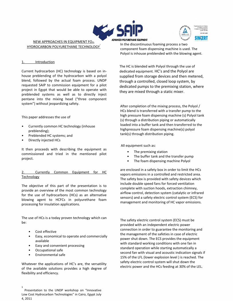
NEW APPROACHES IN EQUIPMENT FOR
HYDROCARBON POLYURETHANE TECHNOLOGY1
In the discontinuous foaming process a two component foam dispensing machine is used. The Polyol is inhouse preblended with the blowing agent.
1. Introduction
Current hydrocarbon (HC) technology is based on in-house preblending of the hydrocarbon with a polyol blend, followed by the actual foam process. UNDP requested SAIP to commission equipment for a pilot project in Egypt that would be able to operate with preblended systems as well as to directly inject pentane into the mixing head (“three component system”) without jeopardizing safety.
This paper addresses the use of
• Currently common HC technology (inhouse preblending);
• Preblended HC systems; and • Directly injected HCs
It then proceeds with describing the equipment as commissioned and tried in the mentioned pilot project.
2. Currently Common Equipment for HC Technology
The objective of this part of the presentation is to provide an overview of the most common technology for the use of hydrocarbons (HCs) as an alternative blowing agent to HCFCs in polyurethane foam processing for insulation applications.
The use of HCs is a today proven technology which can be:
• Cost effective • Easy, economical to operate and commercially
available • Easy and convenient processing • Occupational safe • Environmental safe
Whatever the applications of HC’s are, the versatility of the available solutions provides a high degree of flexibility and efficiency.
1
Presentation to the UNDP workshop on “Innovative Low Cost Hydrocarbon Technologies” in Cairo, Egypt July 4, 2011
The HC is blended with Polyol through the use of
dedicated equipment. HC’s and the Polyol are supplied from storage devices and then metered, through a controlled, closed loop system, by dedicated pumps to the premixing station, where they are mixed through a static mixer.
After completion of the mixing process, the Polyol / HCs blend is transferred with a transfer pump to the high pressure foam dispensing machine (s) Polyol tank (s) through a distribution piping or automatically loaded into a buffer tank and then transferred to the highpressure foam dispensing machine(s) polyol tank(s) through distribution piping.
All equipment such as:
• The premixing station • The buffer tank and the transfer pump • The foam dispensing machine Polyol
are enclosed in a safety box in order to limit the HCs vapors emissions in a controlled and restricted area. The safety box is provided with safety devices which include double speed fans for forced ventilation complete with suction hoods, extraction chimney, airflow control, detection system (catalytic or infrared sensors) and a safety electric control system (ECS) for management and monitoring of HC vapor emissions.
The safety electric control system (ECS) must be provided with an independent electric power connection in order to guarantee the monitoring and the management of the safeties in case of electric power shut down. The ECS provides the equipment with standard working conditions with one fan in standard operation while starting automatically a second fan with visual and acoustic indication signals if 15% of the LFL (lower explosion level ) is reached. The safety electric control system will shut down the electric power and the HCs feeding at 30% of the LEL.
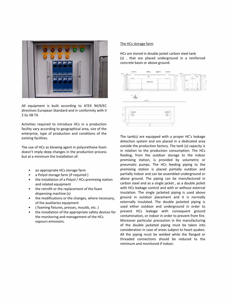
All equipment is built according to ATEX 94/9/EC directives European Standard and in conformity with II 2 Gc IIB T4.
Activities required to introduce HCs in a production facility vary according to geographical area, size of the enterprise, type of production and conditions of the existing facilities.
The use of HCs as blowing agent in polyurethane foam doesn’t imply deep changes in the production process but at a minimum the installation of:
• an appropriate HCs storage farm • a Polyol storage farm (if required ) • the installation of a Polyol / HCs premixing station
and related equipment • the retrofit or the replacement of the foam
dispensing machine (s) • the modifications or the changes, where necessary,
of the auxiliaries equipment • ( foaming fixtures, presses, moulds, etc. ) • the installation of the appropriate safety devices for
the monitoring and management of the HCs vapours emissions.
The HCs storage farm
HCs are stored in double jacket carbon steel tank (s) , that are placed underground in a reinforced concrete basin or above ground.
The tank(s) are equipped with a proper HC’s leakage detection system and are placed in a dedicated area outside the production factory. The tank (s) capacity is in relation to the production consumption. The HCs feeding, from the outdoor storage to the indoor premixing station, is provided by volumetric or pneumatic pumps. The HCs feeding piping to the premixing station is placed partially outdoor and partially indoor and can be assembled underground or above ground. The piping can be manufactured in carbon steel and as a single jacket , as a double jacket with HCs leakage control and with or without external insulation. The single jacketed piping is used above ground in outdoor placement and it is normally externally insulated. The double jacketed piping is used either outdoor and underground in order to prevent HCs leakage with consequent ground contamination, or indoor in order to prevent from fire. Moreover particular precaution in the manufacturing of the double jacketed piping must be taken into consideration in case of areas subject to heart quakes. All the piping must be welded while the flanged or threaded connections should be reduced to the minimum and monitored if indoor.
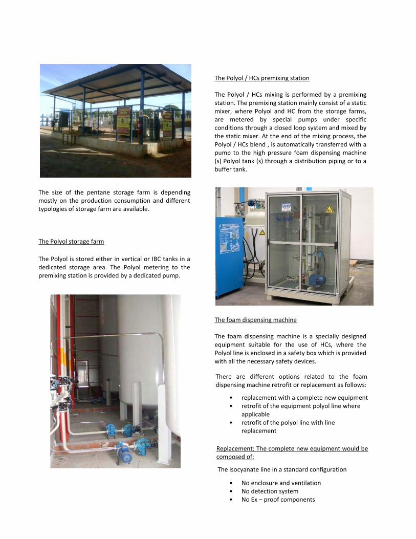
The Polyol / HCs premixing station
The Polyol / HCs mixing is performed by a premixing station. The premixing station mainly consist of a static mixer, where Polyol and HC from the storage farms, are metered by special pumps under specific conditions through a closed loop system and mixed by the static mixer. At the end of the mixing process, the Polyol / HCs blend , is automatically transferred with a pump to the high pressure foam dispensing machine (s) Polyol tank (s) through a distribution piping or to a buffer tank.
The size of the pentane storage farm is depending mostly on the production consumption and different typologies of storage farm are available.
The Polyol storage farm
The Polyol is stored either in vertical or IBC tanks in a dedicated storage area. The Polyol metering to the premixing station is provided by a dedicated pump.
The foam dispensing machine
The foam dispensing machine is a specially designed equipment suitable for the use of HCs, where the Polyol line is enclosed in a safety box which is provided with all the necessary safety devices.
There are different options related to the foam dispensing machine retrofit or replacement as follows:
• replacement with a complete new equipment • retrofit of the equipment polyol line where
applicable • retrofit of the polyol line with line
replacement
Replacement: The complete new equipment would be composed of:
The isocyanate line in a standard configuration
• No enclosure and ventilation • No detection system • No Ex – proof components
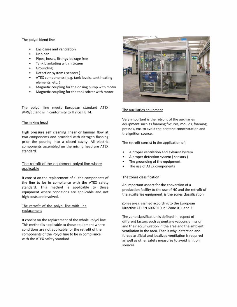
The polyol blend line
• Enclosure and ventilation • Drip pan • Pipes, hoses, fittings leakage free • Tank blanketing with nitrogen • Grounding • Detection system ( sensors ) • ATEX components ( e.g. tank levels, tank heating
elements, etc. ) • Magnetic coupling for the dosing pump with motor • Magnetic coupling for the tank stirrer with motor
The polyol line meets European standard ATEX 94/9/EC and is in conformity to II 2 Gc IIB T4.
The mixing head
High pressure self cleaning linear or laminar flow at two components and provided with nitrogen flushing prior the pouring into a closed cavity. All electric components assembled on the mixing head are ATEX standard.
The retrofit of the equipment polyol line where
applicable
It consist on the replacement of all the components of the line to be in compliance with the ATEX safety standard. This method is applicable to those equipment where conditions are applicable and not high costs are involved.
The retrofit of the polyol line with line replacement
It consist on the replacement of the whole Polyol line. This method is applicable to those equipment where conditions are not applicable for the retrofit of the components of the Polyol line to be in compliance with the ATEX safety standard.
The auxiliaries equipment
Very important is the retrofit of the auxiliaries equipment such as foaming fixtures, moulds, foaming presses, etc. to avoid the pentane concentration and the ignition source.
The retrofit consist in the application of:
• A proper ventilation and exhaust system • A proper detection system ( sensors ) • The grounding of the equipment • The use of ATEX components
The zones classification
An important aspect for the conversion of a production facility to the use of HC and the retrofit of the auxiliaries equipment, is the zones classification.
Zones are classified according to the European Directive CEI EN 6007910 in : Zone 0, 1 and 2.
The zone classification is defined in respect of different factors such as pentane vapours emission and their accumulation in the area and the ambient ventilation in the area. That is why, detection and forced artificial and localized ventilation is required as well as other safety measures to avoid ignition sources.
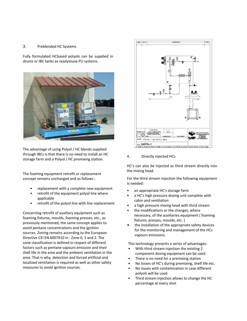
3. Preblended HC Systems
Fully formulated HCbased polyols can be supplied in drums or IBC tanks as readytouse PU systems.
The advantage of using Polyol / HC blends supplied through IBCs is that there is no need to install an HC storage farm and a Polyol / HC premixing station.
The foaming equipment retrofit or replacement concept remains unchanged and as follows :
• replacement with a complete new equipment • retrofit of the equipment polyol line where
applicable • retrofit of the polyol line with line replacement
Concerning retrofit of auxiliary equipment such as foaming fixtures, moulds, foaming presses, etc., as previously mentioned, the same concept applies to avoid pentane concentrations and the ignition sources. Zoning remains according to the European Directive CEI EN 6007910 in : Zone 0, 1 and 2. The zone classification is defined in respect of different factors such as pentane vapours emission and their shell life in the area and the ambient ventilation in the area. That is why, detection and forced artificial and localized ventilation is required as well as other safety measures to avoid ignition sources.
4. Directly injected HCs
HC’s can also be injected as third stream directly into the mixing head.
For the third stream injection the following equipment is needed:
• an appropriate HC’s storage farm • a HC’s high pressure dosing unit complete with
cabin and ventilation • a high pressure mixing head with third stream • the modifications or the changes, where
necessary, of the auxiliaries equipment ( foaming fixtures, presses, moulds, etc. )
• • the installation of the appropriate safety devices for the monitoring and management of the HCs vapours emissions.
This technology presents a series of advantages: • With third stream injection the existing 2
component dosing equipment can be used • There is no need for a premixing station • No losses of HC’s during premixing, shelf life etc. • No issues with contamination in case different
polyols will be used • Third stream injection allows to change the HC
percentage at every shot
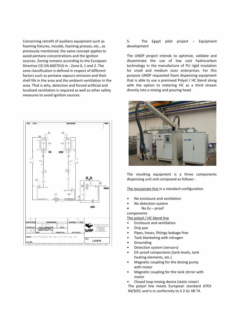
Concerning retrofit of auxiliary equipment such as foaming fixtures, moulds, foaming presses, etc., as previously mentioned, the same concept applies to avoid pentane concentrations and the ignition sources. Zoning remains according to the European Directive CEI EN 6007910 in : Zone 0, 1 and 2. The zone classification is defined in respect of different factors such as pentane vapours emission and their shell life in the area and the ambient ventilation in the area. That is why, detection and forced artificial and localized ventilation is required as well as other safety measures to avoid ignition sources.
5. The Egypt pilot project – Equipment development
The UNDP project intends to optimize, validate and disseminate the use of low cost hydrocarbon technology in the manufacture of PU rigid insulation for small and medium sizes enterprises. For this purpose UNDP requested foam dispensing equipment that is able to use a premixed Polyol / HC blend along with the option to metering HC as a third stream directly into a mixing and pouring head.
The resulting equipment is a three components dispensing unit and composed as follows :
The isocyanate line in a standard configuration
• No enclosure and ventilation • No detection system • • No Ex – proof components The polyol / HC blend line • Enclosure and ventilation • Drip pan • Pipes, hoses, fittings leakage free • Tank blanketing with nitrogen • Grounding • Detection system (sensors) • EX–proof components (tank levels, tank
heating elements, etc.) • Magnetic coupling for the dosing pump
with motor • Magnetic coupling for the tank stirrer with
motor • Closed loop mixing device (static mixer) The polyol line meets European standard ATEX 94/9/EC and is in conformity to II 2 Gc IIB T4.
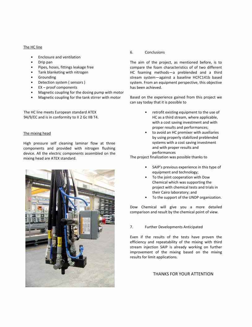
The HC line
• Enclosure and ventilation • Drip pan • Pipes, hoses, fittings leakage free • Tank blanketing with nitrogen • Grounding • Detection system ( sensors ) • EX – proof components • Magnetic coupling for the dosing pump with motor • Magnetic coupling for the tank stirrer with motor
The mixing head
High pressure self cleaning laminar flow at three components and provided with nitrogen flushing device. All the electric components assembled on the mixing head are ATEX standard.
6. Conclusions
The aim of the project, as mentioned before, is to compare the foam characteristics of of two different HC foaming methods—a preblended and a third stream system—against a baseline HCFC141b based system. From an equipment perspective, this objective has been achieved.
Based on the experience gained from this project we can say today that it is possible to
• retrofit existing equipment to the use of HC as a third stream, where applicable, with a cost saving investment and with proper results and performances;
• to avoid an HC premixer with auxiliaries by using properly stabilized preblended systems with a cost saving investment and with proper results and performances
The project finalization was possible thanks to
• SAIP’s previous experience in this type of equipment and technology;
• To the joint cooperation with Dow Chemical which was supporting the project with chemical tests and trials in their Cairo laboratory; and
• To the support of the UNDP organization.
The HC line meets European standard ATEX 94/9/EC and is in conformity to II 2 Gc IIB T4.
Dow Chemical will give you a more detailed comparison and result by the chemical point of view.
7. Further Developments Anticipated
Even if the results of the tests have proven the efficiency and repeatability of the mixing with third stream injection SAIP is already working on further improvement of the mixing based on the mixing results for limit applications.
THANKS FOR YOUR ATTENTION
HC Pilot project Egypt Submitted May 11, 2009
ATTACHMENT V
UNDP Egypt project workshop, Cairo 2011 The Dow Chemical Company Report of data generated in DOW Cairo Polyurethane System House laboratory with DOW systems and SAIP novel high pressure dispensing machine for discontinuous production processes, convertible from traditional pre-blended pentane injection to third stream pentane addition directly in the mix head. Sustainability is a key challenge for many industries around the world. DOW Formulated Systems, as the polyurethane industry is strongly committed to this theme by continuously developing formulations and solutions that help preserving the environment. In particular Rigid Foams, with their insulation performance, significantly contribute to meet energy-saving requirements. The development of sustainable polyurethanes formulations includes the transition from blowing agents (BAs) showing an Ozone Depletion Potential (ODP) to Zero ODP technologies. The selection of the right alternative blowing agent technology and machine to dispense it should be guided by the critical foam performance and production process requirement, that differ application by application and even producer by producer. In general DOW Formulated Systems works on a broad spectrum of solutions and blowing agents, and has a broad portfolio of Rigid Foam systems for all the different applications in consideration of the fact that each customer type has its own needs and need tailored solutions. On top of collaborating directly with its customers, Dow is also active in collaborate in external initiatives related to sustainable and effective technologies, aiming at their dissemination, or to test new options that could make them more affordable to the industry. For this reason DOW has made its products and laboratory available for the specific of this UNDP project, to host SAIP equipment and generate data. Among proven Zero ODP blowing agent options, which include hydrocarbons, hydro-fluorocarbons and water, hydrocarbons are the most utilized, thanks to the good mix of performance features (final foam properties, processing window, cycle time) and low cost, in particular in the domestic appliance industry and continuous laminated sandwich panels industry, but not only. Still, part of the smaller producers in applications like for example commercial appliances, water heaters and discontinuous panels, face the limitation of the investment required to handle the flammability aspects. Worth to remind that other technologies are available that do not require particular investment, like water blown, that despite it cannot compete with hydrocarbons in terms of applied density and thermal conductivity, represents a good bridge technology for some of the producers, and also high water / low HFC level technologies, which mitigate the HFCs GWP impact, and can help producers to bridge time till new Zero ODP and low GWP blowing agents like HFOs will be available. Product design with pentane for discontinuous applications along the years addressed various potential initial issues like higher flammability of foams blown with pentane, that needed to be properly addressed by polymer modification, and the different properties of the various pentane isomers, which differ in polyol solubility, thermal insulation performance and boiling temperature, with impact on processing and final foam properties. Typical discontinuous foam production process involves the addition of pentane to the polyol component via a premix unit before metering and the recycling of the blend through the mixing head, therefore a homogeneous blend of the polyol with pentane is needed. Table 1 below reports properties of the different pentane isomers, in a comparative with HCFC141b and other Zero ODP molecules.
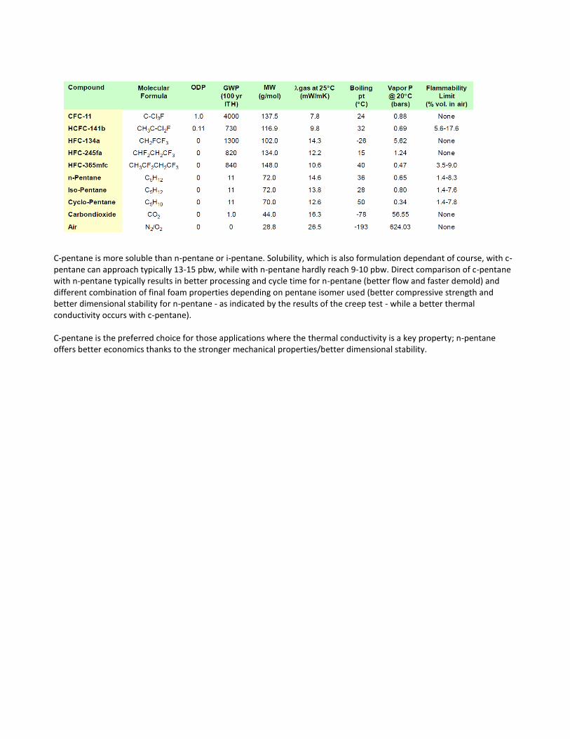
C-pentane is more soluble than n-pentane or i-pentane. Solubility, which is also formulation dependant of course, with c-pentane can approach typically 13-15 pbw, while with n-pentane hardly reach 9-10 pbw. Direct comparison of c-pentane with n-pentane typically results in better processing and cycle time for n-pentane (better flow and faster demold) and different combination of final foam properties depending on pentane isomer used (better compressive strength and better dimensional stability for n-pentane - as indicated by the results of the creep test - while a better thermal conductivity occurs with c-pentane). C-pentane is the preferred choice for those applications where the thermal conductivity is a key property; n-pentane offers better economics thanks to the stronger mechanical properties/better dimensional stability.
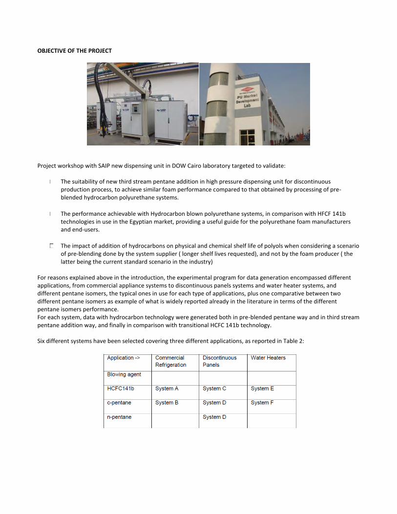
OBJECTIVE OF THE PROJECT
Project workshop with SAIP new dispensing unit in DOW Cairo laboratory targeted to validate:
The suitability of new third stream pentane addition in high pressure dispensing unit for discontinuous production process, to achieve similar foam performance compared to that obtained by processing of pre-blended hydrocarbon polyurethane systems.
The performance achievable with Hydrocarbon blown polyurethane systems, in comparison with HFCF 141b technologies in use in the Egyptian market, providing a useful guide for the polyurethane foam manufacturers and end-users.
The impact of addition of hydrocarbons on physical and chemical shelf life of polyols when considering a scenario of pre-blending done by the system supplier ( longer shelf lives requested), and not by the foam producer ( the latter being the current standard scenario in the industry)
For reasons explained above in the introduction, the experimental program for data generation encompassed different applications, from commercial appliance systems to discontinuous panels systems and water heater systems, and different pentane isomers, the typical ones in use for each type of applications, plus one comparative between two different pentane isomers as example of what is widely reported already in the literature in terms of the different pentane isomers performance. For each system, data with hydrocarbon technology were generated both in pre-blended pentane way and in third stream pentane addition way, and finally in comparison with transitional HCFC 141b technology. Six different systems have been selected covering three different applications, as reported in Table 2:
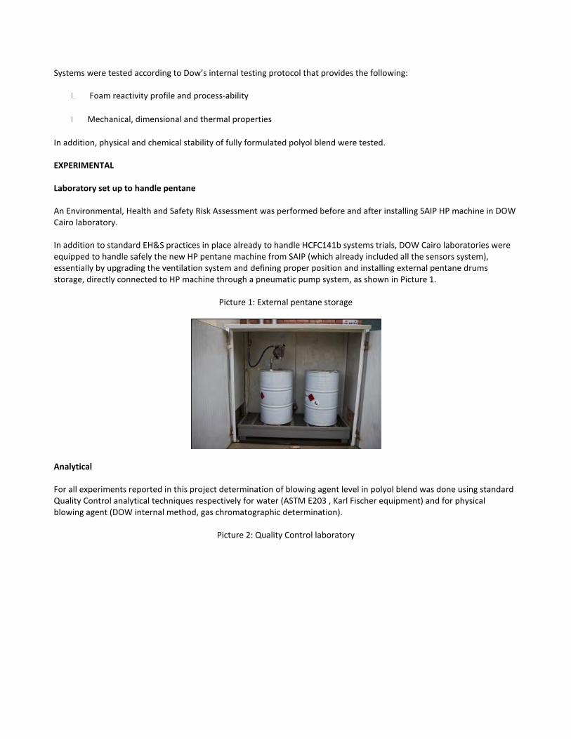
Systems were tested according to Dow’s internal testing protocol that provides the following:
Foam reactivity profile and process-ability
Mechanical, dimensional and thermal properties
In addition, physical and chemical stability of fully formulated polyol blend were tested. EXPERIMENTAL Laboratory set up to handle pentane An Environmental, Health and Safety Risk Assessment was performed before and after installing SAIP HP machine in DOW Cairo laboratory. In addition to standard EH&S practices in place already to handle HCFC141b systems trials, DOW Cairo laboratories were equipped to handle safely the new HP pentane machine from SAIP (which already included all the sensors system), essentially by upgrading the ventilation system and defining proper position and installing external pentane drums storage, directly connected to HP machine through a pneumatic pump system, as shown in Picture 1.
Picture 1: External pentane storage
Analytical For all experiments reported in this project determination of blowing agent level in polyol blend was done using standard Quality Control analytical techniques respectively for water (ASTM E203 , Karl Fischer equipment) and for physical blowing agent (DOW internal method, gas chromatographic determination).
Picture 2: Quality Control laboratory
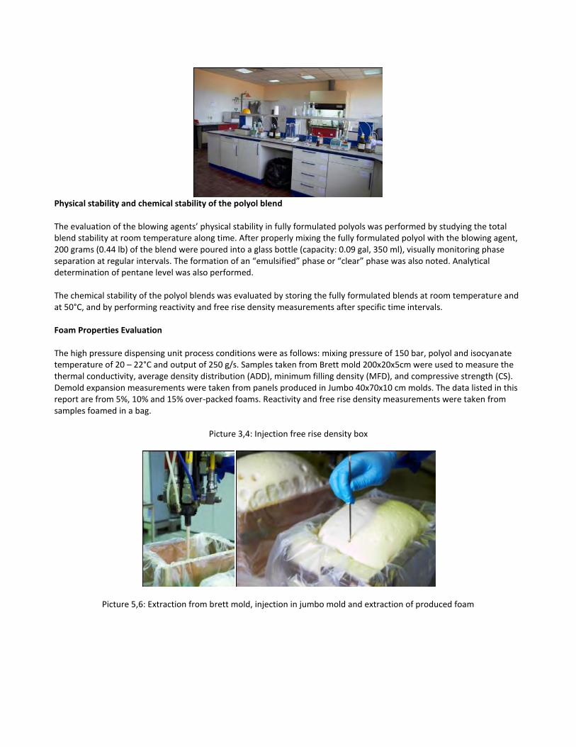
Physical stability and chemical stability of the polyol blend The evaluation of the blowing agents’ physical stability in fully formulated polyols was performed by studying the total blend stability at room temperature along time. After properly mixing the fully formulated polyol with the blowing agent, 200 grams (0.44 lb) of the blend were poured into a glass bottle (capacity: 0.09 gal, 350 ml), visually monitoring phase separation at regular intervals. The formation of an “emulsified” phase or “clear” phase was also noted. Analytical determination of pentane level was also performed. The chemical stability of the polyol blends was evaluated by storing the fully formulated blends at room temperature and at 50°C, and by performing reactivity and free rise density measurements after specific time intervals.
Foam Properties Evaluation The high pressure dispensing unit process conditions were as follows: mixing pressure of 150 bar, polyol and isocyanate temperature of 20 – 22°C and output of 250 g/s. Samples taken from Brett mold 200x20x5cm were used to measure the thermal conductivity, average density distribution (ADD), minimum filling density (MFD), and compressive strength (CS). Demold expansion measurements were taken from panels produced in Jumbo 40x70x10 cm molds. The data listed in this report are from 5%, 10% and 15% over-packed foams. Reactivity and free rise density measurements were taken from samples foamed in a bag.
Picture 3,4: Injection free rise density box
Picture 5,6: Extraction from brett mold, injection in jumbo mold and extraction of produced foam
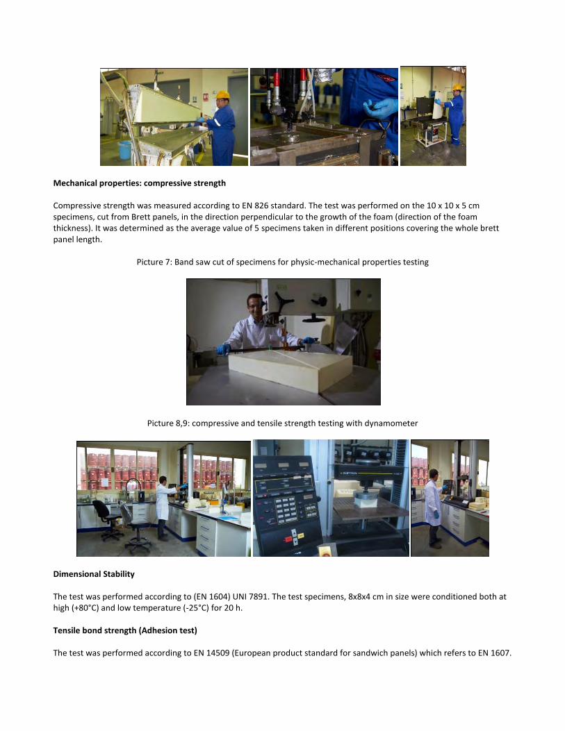
Mechanical properties: compressive strength Compressive strength was measured according to EN 826 standard. The test was performed on the 10 x 10 x 5 cm specimens, cut from Brett panels, in the direction perpendicular to the growth of the foam (direction of the foam thickness). It was determined as the average value of 5 specimens taken in different positions covering the whole brett panel length.
Picture 7: Band saw cut of specimens for physic-mechanical properties testing
Picture 8,9: compressive and tensile strength testing with dynamometer
Dimensional Stability The test was performed according to (EN 1604) UNI 7891. The test specimens, 8x8x4 cm in size were conditioned both at high (+80°C) and low temperature (-25°C) for 20 h. Tensile bond strength (Adhesion test) The test was performed according to EN 14509 (European product standard for sandwich panels) which refers to EN 1607.
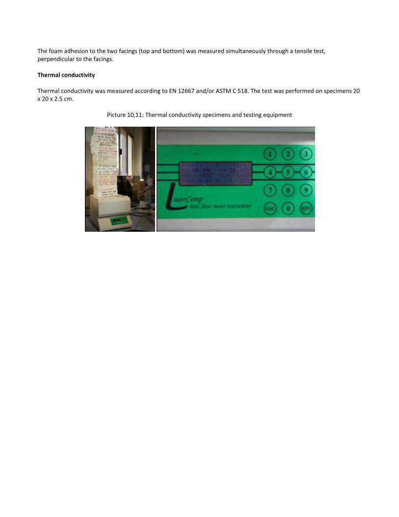
The foam adhesion to the two facings (top and bottom) was measured simultaneously through a tensile test, perpendicular to the facings. Thermal conductivity Thermal conductivity was measured according to EN 12667 and/or ASTM C 518. The test was performed on specimens 20 x 20 x 2.5 cm.
Picture 10,11: Thermal conductivity specimens and testing equipment
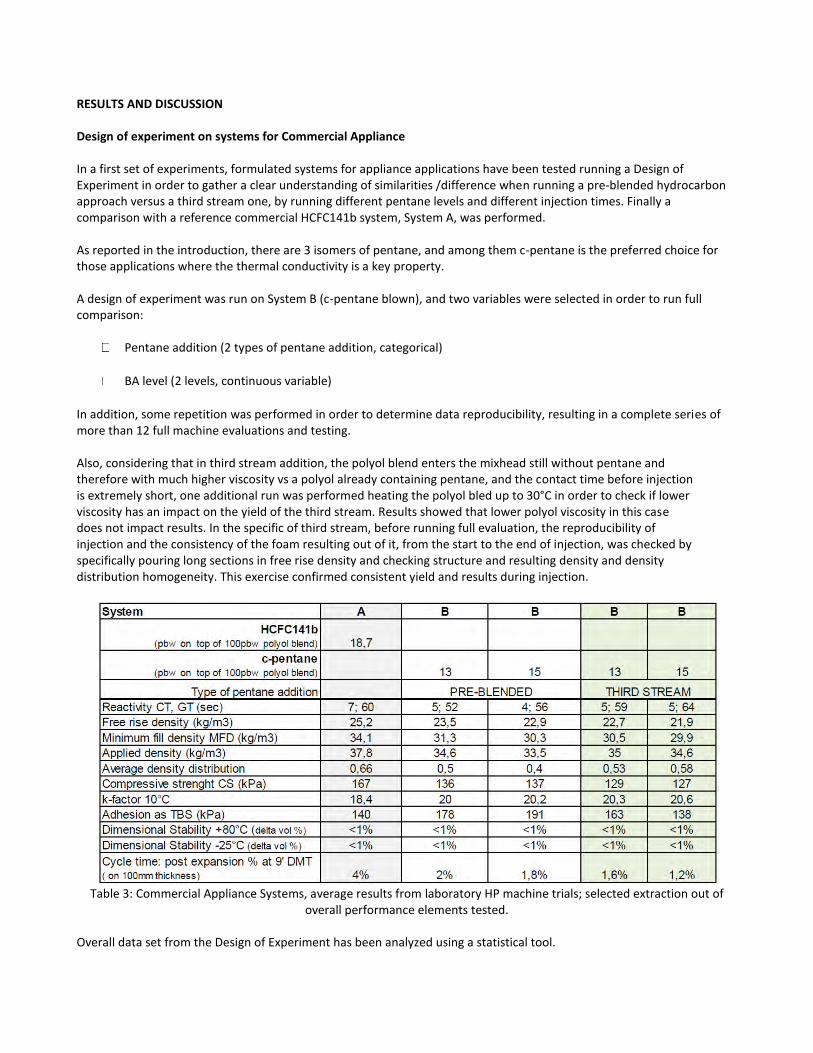
RESULTS AND DISCUSSION Design of experiment on systems for Commercial Appliance In a first set of experiments, formulated systems for appliance applications have been tested running a Design of Experiment in order to gather a clear understanding of similarities /difference when running a pre-blended hydrocarbon approach versus a third stream one, by running different pentane levels and different injection times. Finally a comparison with a reference commercial HCFC141b system, System A, was performed. As reported in the introduction, there are 3 isomers of pentane, and among them c-pentane is the preferred choice for those applications where the thermal conductivity is a key property. A design of experiment was run on System B (c-pentane blown), and two variables were selected in order to run full comparison:
Pentane addition (2 types of pentane addition, categorical)
BA level (2 levels, continuous variable)
In addition, some repetition was performed in order to determine data reproducibility, resulting in a complete series of more than 12 full machine evaluations and testing. Also, considering that in third stream addition, the polyol blend enters the mixhead still without pentane and therefore with much higher viscosity vs a polyol already containing pentane, and the contact time before injection is extremely short, one additional run was performed heating the polyol bled up to 30°C in order to check if lower viscosity has an impact on the yield of the third stream. Results showed that lower polyol viscosity in this case does not impact results. In the specific of third stream, before running full evaluation, the reproducibility of injection and the consistency of the foam resulting out of it, from the start to the end of injection, was checked by specifically pouring long sections in free rise density and checking structure and resulting density and density distribution homogeneity. This exercise confirmed consistent yield and results during injection.
Table 3: Commercial Appliance Systems, average results from laboratory HP machine trials; selected extraction out of
overall performance elements tested.
Overall data set from the Design of Experiment has been analyzed using a statistical tool.
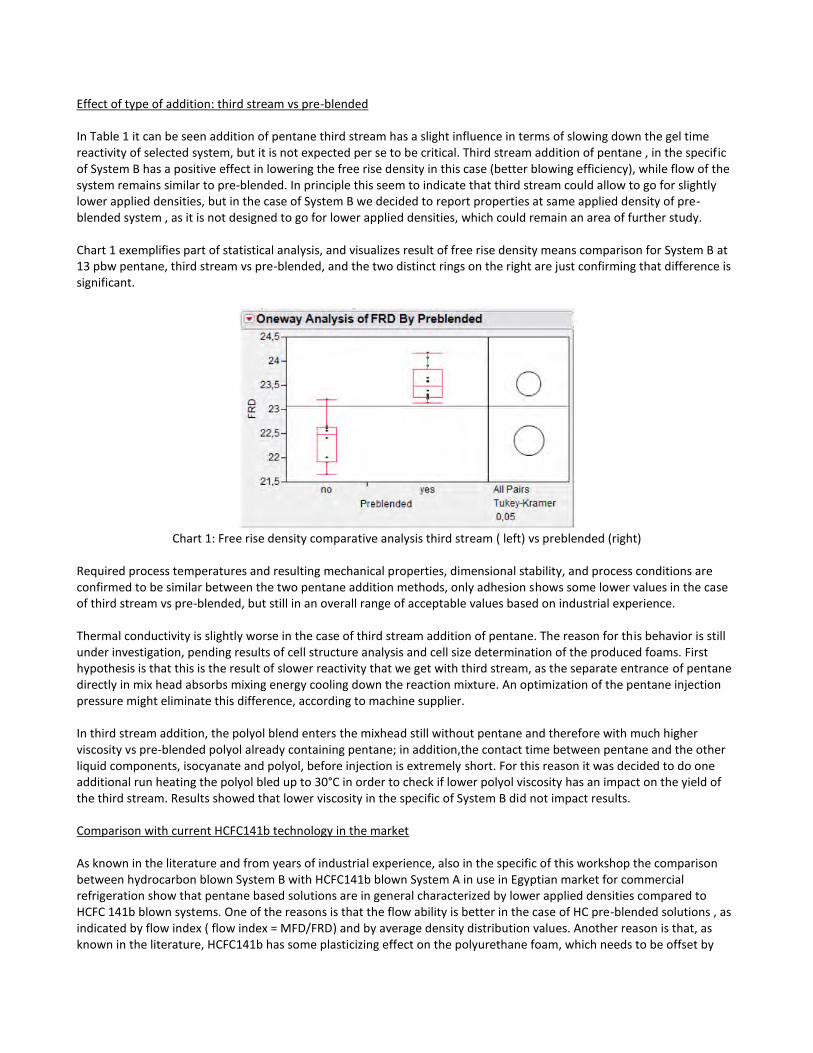
Effect of type of addition: third stream vs pre-blended In Table 1 it can be seen addition of pentane third stream has a slight influence in terms of slowing down the gel time reactivity of selected system, but it is not expected per se to be critical. Third stream addition of pentane , in the specific of System B has a positive effect in lowering the free rise density in this case (better blowing efficiency), while flow of the system remains similar to pre-blended. In principle this seem to indicate that third stream could allow to go for slightly lower applied densities, but in the case of System B we decided to report properties at same applied density of pre-blended system , as it is not designed to go for lower applied densities, which could remain an area of further study. Chart 1 exemplifies part of statistical analysis, and visualizes result of free rise density means comparison for System B at 13 pbw pentane, third stream vs pre-blended, and the two distinct rings on the right are just confirming that difference is significant.
Chart 1: Free rise density comparative analysis third stream ( left) vs preblended (right)
Required process temperatures and resulting mechanical properties, dimensional stability, and process conditions are confirmed to be similar between the two pentane addition methods, only adhesion shows some lower values in the case of third stream vs pre-blended, but still in an overall range of acceptable values based on industrial experience. Thermal conductivity is slightly worse in the case of third stream addition of pentane. The reason for this behavior is still under investigation, pending results of cell structure analysis and cell size determination of the produced foams. First hypothesis is that this is the result of slower reactivity that we get with third stream, as the separate entrance of pentane directly in mix head absorbs mixing energy cooling down the reaction mixture. An optimization of the pentane injection pressure might eliminate this difference, according to machine supplier. In third stream addition, the polyol blend enters the mixhead still without pentane and therefore with much higher viscosity vs pre-blended polyol already containing pentane; in addition,the contact time between pentane and the other liquid components, isocyanate and polyol, before injection is extremely short. For this reason it was decided to do one additional run heating the polyol bled up to 30°C in order to check if lower polyol viscosity has an impact on the yield of the third stream. Results showed that lower viscosity in the specific of System B did not impact results. Comparison with current HCFC141b technology in the market As known in the literature and from years of industrial experience, also in the specific of this workshop the comparison between hydrocarbon blown System B with HCFC141b blown System A in use in Egyptian market for commercial refrigeration show that pentane based solutions are in general characterized by lower applied densities compared to HCFC 141b blown systems. One of the reasons is that the flow ability is better in the case of HC pre-blended solutions , as indicated by flow index ( flow index = MFD/FRD) and by average density distribution values. Another reason is that, as known in the literature, HCFC141b has some plasticizing effect on the polyurethane foam, which needs to be offset by
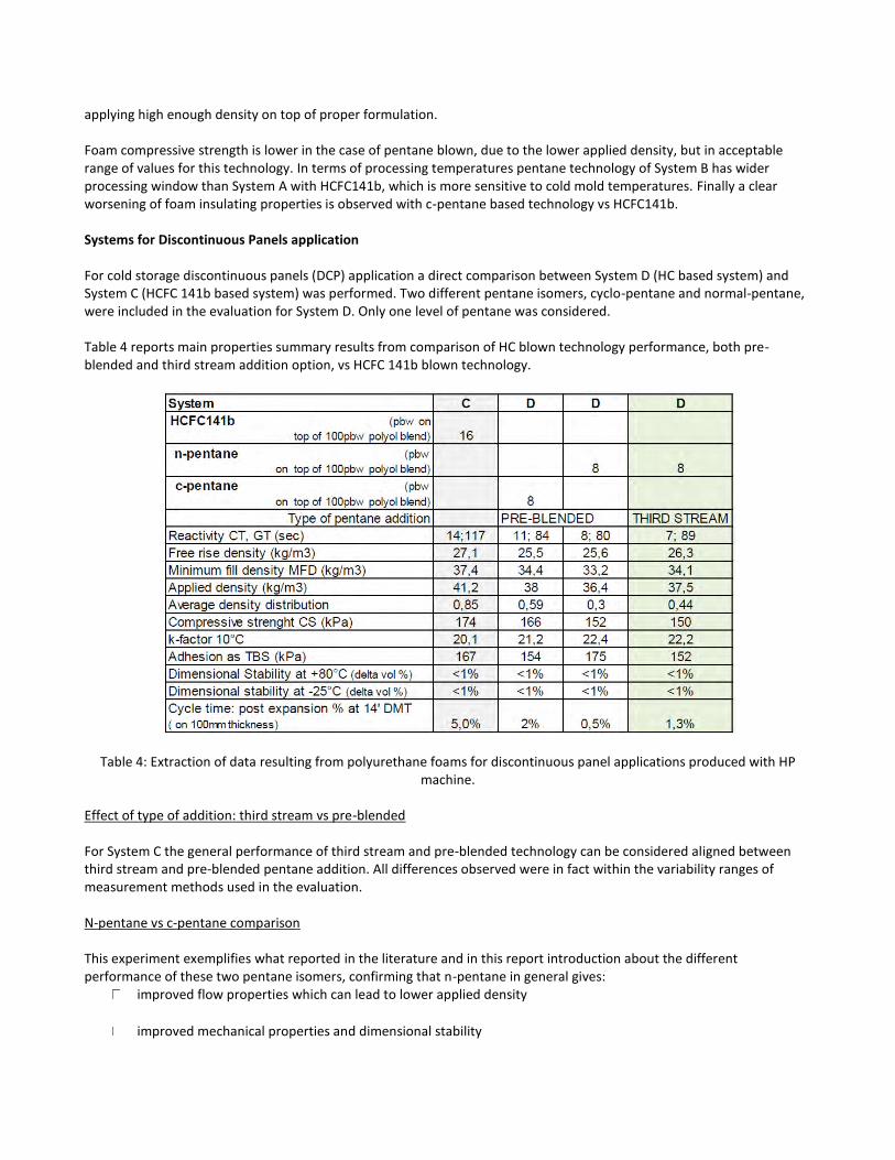
applying high enough density on top of proper formulation. Foam compressive strength is lower in the case of pentane blown, due to the lower applied density, but in acceptable range of values for this technology. In terms of processing temperatures pentane technology of System B has wider processing window than System A with HCFC141b, which is more sensitive to cold mold temperatures. Finally a clear worsening of foam insulating properties is observed with c-pentane based technology vs HCFC141b. Systems for Discontinuous Panels application For cold storage discontinuous panels (DCP) application a direct comparison between System D (HC based system) and System C (HCFC 141b based system) was performed. Two different pentane isomers, cyclo-pentane and normal-pentane, were included in the evaluation for System D. Only one level of pentane was considered. Table 4 reports main properties summary results from comparison of HC blown technology performance, both pre-blended and third stream addition option, vs HCFC 141b blown technology.
Table 4: Extraction of data resulting from polyurethane foams for discontinuous panel applications produced with HP machine.
Effect of type of addition: third stream vs pre-blended For System C the general performance of third stream and pre-blended technology can be considered aligned between third stream and pre-blended pentane addition. All differences observed were in fact within the variability ranges of measurement methods used in the evaluation. N-pentane vs c-pentane comparison This experiment exemplifies what reported in the literature and in this report introduction about the different performance of these two pentane isomers, confirming that n-pentane in general gives:
improved flow properties which can lead to lower applied density
improved mechanical properties and dimensional stability
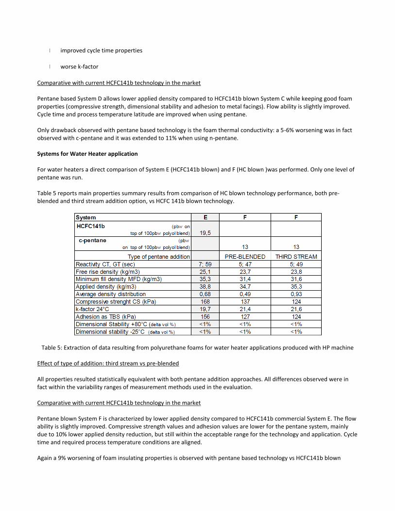
improved cycle time properties
worse k-factor
Comparative with current HCFC141b technology in the market Pentane based System D allows lower applied density compared to HCFC141b blown System C while keeping good foam properties (compressive strength, dimensional stability and adhesion to metal facings). Flow ability is slightly improved. Cycle time and process temperature latitude are improved when using pentane. Only drawback observed with pentane based technology is the foam thermal conductivity: a 5-6% worsening was in fact observed with c-pentane and it was extended to 11% when using n-pentane. Systems for Water Heater application For water heaters a direct comparison of System E (HCFC141b blown) and F (HC blown )was performed. Only one level of pentane was run. Table 5 reports main properties summary results from comparison of HC blown technology performance, both pre-blended and third stream addition option, vs HCFC 141b blown technology.
Table 5: Extraction of data resulting from polyurethane foams for water heater applications produced with HP machine
Effect of type of addition: third stream vs pre-blended All properties resulted statistically equivalent with both pentane addition approaches. All differences observed were in fact within the variability ranges of measurement methods used in the evaluation. Comparative with current HCFC141b technology in the market Pentane blown System F is characterized by lower applied density compared to HCFC141b commercial System E. The flow ability is slightly improved. Compressive strength values and adhesion values are lower for the pentane system, mainly due to 10% lower applied density reduction, but still within the acceptable range for the technology and application. Cycle time and required process temperature conditions are aligned. Again a 9% worsening of foam insulating properties is observed with pentane based technology vs HCFC141b blown
system. Shelf life study on pentane pre-blended systems. Most standard practice today in the industry is to have polyol blend supplied without pentane to the foam manufacturers by system supplier, and then foam manufacturers directly pre-blendes at his site the pentane to the polyol blend through a premix unit. This type of operation typically does not require pentane to be stable in polyol blend for long time, and shelf life of polyol blends without pentane is not critical. A different situation would be represented by a practice where the system supplier already pre-blends pentane in its polyol blend, and supplies it fully formulated to the foam manufacturer. In this case pentane would need to be stable in the polyol blend for some months, typically 6 months, which in principle is a quite critical situation especially for the less soluble pentane isomers like n-pentane, and extremely critical situation in case the suggested storage temperature conditions both during handling, shipping and storage are not fully respected. Of course the shelf life behavior would be formulation dependant as well. Worth to mention that is this second scenario, the topic of investing to handle flammability aspects and risks of pentane would be extended to a larger number of players, as supplier would have to invest to handle pentane in its operation, and as polyol blends containing pentane have flash point and are flammable materials, with additional costs upstream in the value chain to be sustained by suppliers, and that would reflect into system price. Nevertheless, in order to understand the criticality of such scenario, shelf life of pre-blended polyol with pentane was studied for a prolonged time period to understand criticality. System B (c-pentane blown) for commercial appliance was tested, and also System D (n-pentane blown) for cold room discontinuous panels was tested. The evaluation of pentane physical stability in fully formulated polyol stored in 1 liter bottles was performed by studying the blend stability at two temperatures, room temperature and 50°C, during time, preparing pre-blends as discussed in the experimental section. Visual inspection was run at regular intervals. The formation of an “emulsified” phase or “clear” phase was also noted. The evaluation of fully formulated blends chemical stability was performed only in case physical stability was still ok, and it was done by performing reactivity and free rise density measurements after specific intervals. For this study the same systems utilized in the rest of the project were studied, and not reformulation work has been done, in particular System B (c-pentane blown) and System D (n-pentane blown). Aging of blends is still ongoing, at this stage we have reached 3.5 months for the c-pentane system tested, and we have stopped the aging of the n-pentane system for reasons reported below. c-pentane preblended polyols physical and chemical stability 3 months aging of fully formulated polyol of system B containing c-pentane gave good physical stability at room temperature, with no c-pentane separation observed, as reported in Table 6 below. On the other side it is clear from analytical that sample with higher initial level of pentane lost more pentane during aging ( data are not representative exactly of what would happen in bigger containers like drums or IBCs, but should be taken as indications). Temperature of 50°C is more critical and resulted in a color change of the blend. Chemical stability is almost ok at room temperature, with some acceleration of reactivity partially due to loss of pentane, while at high temperature more variation is appreciated along time, with high loss of pentane from liquid phase (despite bottles sealing) during storage and operations.
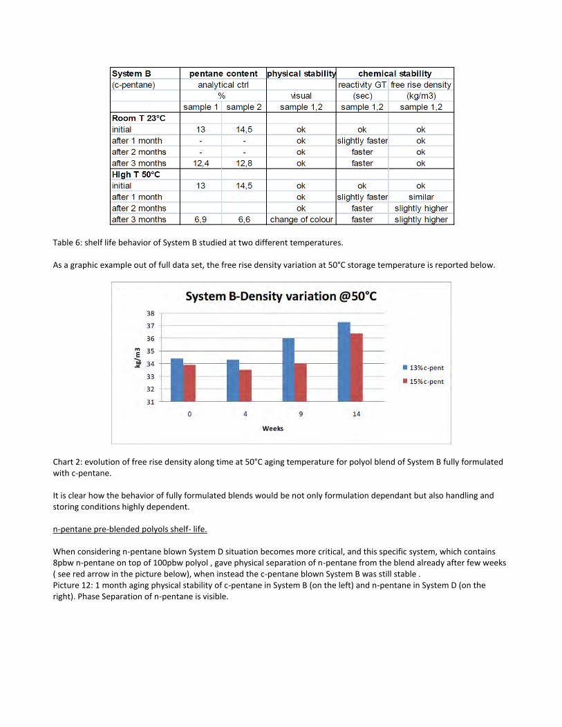
Table 6: shelf life behavior of System B studied at two different temperatures. As a graphic example out of full data set, the free rise density variation at 50°C storage temperature is reported below.
Chart 2: evolution of free rise density along time at 50°C aging temperature for polyol blend of System B fully formulated with c-pentane. It is clear how the behavior of fully formulated blends would be not only formulation dependant but also handling and storing conditions highly dependent. n-pentane pre-blended polyols shelf- life. When considering n-pentane blown System D situation becomes more critical, and this specific system, which contains 8pbw n-pentane on top of 100pbw polyol , gave physical separation of n-pentane from the blend already after few weeks ( see red arrow in the picture below), when instead the c-pentane blown System B was still stable . Picture 12: 1 month aging physical stability of c-pentane in System B (on the left) and n-pentane in System D (on the right). Phase Separation of n-pentane is visible.
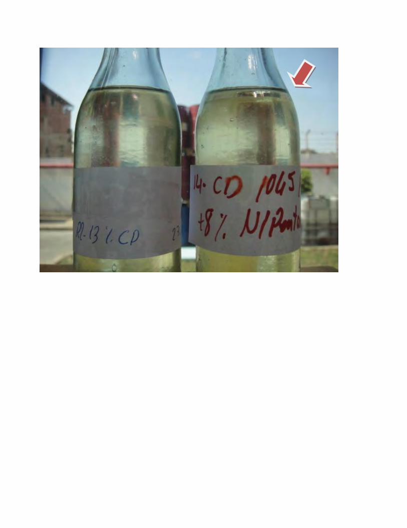
CONCLUSIONS Outcome of this project according to initial objectives can be summarized as follows:
o new high pressure dispensing unit, convertible from 2 component isocyanate/pre-blended hydrocarbon polyols use into 3 components isocyanate/polyol without pentane/third stream pentane addition directly in the mixing head , is validated to be working properly across the two type of injection process
-BLENDED HYDROCARBONS
o Pre-blended hydrocarbons technology, as known in the literature and from industrial experience of various years , are confirmed to give a good pattern of foam properties.
o Most standard practice today in the industry is foam manufacturer doing the pre-blend directly at its production site, which requires very limited shelf life of fully formulated polyol , with no particular criticality given proper formulation .
o In a different scenario of pre-blending, where addition of hydrocarbons would take place already by system supplier, longer time pentane stability in the polyol blend would be required, typically 6 months shelf life, increasing criticality, especially in case of the less soluble pentane isomers.
o Physical and chemical stability tests on fully formulated polyol blends containing pentane to predict a 6 months shelf life (still ongoing) indicate already that n-pentane System D is not suitable for extended pre-blend shelf life, while the c-pentane System B behave reasonably so far for a period of 3 months with 13 pbw pentane on top of 100 pbw polyol was used. It is recognized that shelf life is also dependant on formulation of specific system.
o Future work: aging of fully formulated polyol with c-pentane will continue upon reaching 6 months and shelf life results will be reported. A tailored formulation with n-pentane will also be checked to complete assessment about criticality of n-pentane for a 6 months shelf life. Expectation is that in any case n-pentane blends would remain very critical, with impact on the level of physical blowing agent that can be kept stable in the polyol blend.
o Third stream addition of pentane directly in the mixing head is confirmed to be working with good reproducibility and consistency across different injections duration, giving homogeneous results.
o Future work: Optimization of pentane impingement pressure and reactivity will be done to close the delta in gel time and thermal conductivity that were observed vs pre-blended process
o The performance achievable with Hydrocarbon blown polyurethane systems, in comparison with HFCF 141b technologies in use in the Egyptian market, confirms “generation 1” hydrocarbon systems are effective alternative for polyurethane foam producers to move into Zero ODP (also low GWP) more sustainable solutions.
o This comparison has to be considered valid for other countries as well
o Hydrocarbon blown systems utilized in the workshop are already in use in developed countries, with successful track records.
o The experiments within the scope of this project were performed in accordance with the recommendations from an Environmental, Health and Safety Risk Assessment.
o Replication of these experiments should only be performed after completing Environmental, Health and Safety Risk Assessment by a qualified professional.
o Reference to the Material Safety Data Sheets for Environmental, Health and Safety information on the substances used in this project and to dispensing unit documentation from equipment suppliers must be made.
o In particular, for Environmental, Health and Safety aspects relative to third stream pentane addition handling and storage connection, reference must be made to documentation from the equipment supplier.
Authors Cecilia Girotti is Sr. Chemist R&D for Polyurethane Rigid Foams of Dow Formulated Systems and is located in Correggio, Italy. She joined Dow in 2002 and before her current position she was responsible for managing the physic-mechanical foam testing laboratory in Correggio. Cecilia has a MS in Chemistry from the University of Modena (Italy, 1999). Francesca Pignagnoli is Global Business Development Leader for DOW Energy Efficiency Formulated Systems and is located in Correggio, Italy. She joined DOW in 1997 and before her current position she was Global Development leader managing R&D group for Rigid Polyurethane Systems. Francesca has a MS in Organic Chemistry from the University of Parma (Italy, 1995). Mohammed El Fikky is Technical and Sales Representative for DOW Energy Efficiency Formulated Systems ad is located in Cairo, Egypt. He joined DOW in 1998 and before his current position he was responsible for the TS&D laboratory Supervisor, Mohamed has a B.Sc in Chemical Engineering from the Higher Technological Institute, 10th of Ramadan City (Egypt, 1996) Acknowledgments A particular thank to Amr Badawi, DOW Cairo System House TS&D Laboratory Supervisor, and all the technical staff with him in Cairo that supported the project. As well, a particular thank to SAIP technical team and Cairo agent, who collaborated actively along various steps of the experimental program to allow DOW team to use the new SAIP machine in the best conditions, and to UNDP for allowing DOW team the use of the new SAIP dispenser under optimal conditions.
HC Pilot project Egypt Submitted May 11, 2009
ATTACHMENT VI
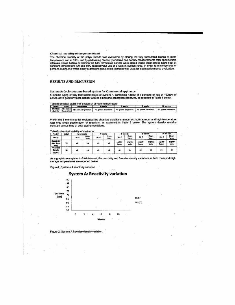
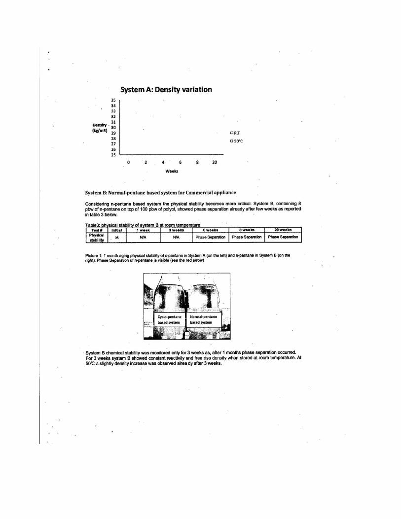
![Nitrogen-doped carbon nanosheets from polyurethane foams ...carbonlett.org/Upload/files/CARBONLETT/[060-069]-07.pdf · Nitrogen-doped carbon nanosheets from polyurethane foams and](https://img.pdfslide.us/doc/110x75/5b6d7e8f7f8b9a3b388cf74e/nitrogen-doped-carbon-nanosheets-from-polyurethane-foams-060-069-07pdf.jpg)