Embed Size (px)
Citation preview
2015 Microchip Technology Inc. DS40001818A
Low-Cost mTouch®
Evaluation KitUser’s Guide
DS40001818A-page 2 2015 Microchip Technology Inc.
Information contained in this publication regarding deviceapplications and the like is provided only for your convenienceand may be superseded by updates. It is your responsibility toensure that your application meets with your specifications.MICROCHIP MAKES NO REPRESENTATIONS ORWARRANTIES OF ANY KIND WHETHER EXPRESS ORIMPLIED, WRITTEN OR ORAL, STATUTORY OROTHERWISE, RELATED TO THE INFORMATION,INCLUDING BUT NOT LIMITED TO ITS CONDITION,QUALITY, PERFORMANCE, MERCHANTABILITY ORFITNESS FOR PURPOSE. Microchip disclaims all liabilityarising from this information and its use. Use of Microchipdevices in life support and/or safety applications is entirely atthe buyer’s risk, and the buyer agrees to defend, indemnify andhold harmless Microchip from any and all damages, claims,suits, or expenses resulting from such use. No licenses areconveyed, implicitly or otherwise, under any Microchipintellectual property rights unless otherwise stated.
Note the following details of the code protection feature on Microchip devices:
• Microchip products meet the specification contained in their particular Microchip Data Sheet.
• Microchip believes that its family of products is one of the most secure families of its kind on the market today, when used in the intended manner and under normal conditions.
• There are dishonest and possibly illegal methods used to breach the code protection feature. All of these methods, to our knowledge, require using the Microchip products in a manner outside the operating specifications contained in Microchip’s Data Sheets. Most likely, the person doing so is engaged in theft of intellectual property.
• Microchip is willing to work with the customer who is concerned about the integrity of their code.
• Neither Microchip nor any other semiconductor manufacturer can guarantee the security of their code. Code protection does not mean that we are guaranteeing the product as “unbreakable.”
Code protection is constantly evolving. We at Microchip are committed to continuously improving the code protection features of ourproducts. Attempts to break Microchip’s code protection feature may be a violation of the Digital Millennium Copyright Act. If such actsallow unauthorized access to your software or other copyrighted work, you may have a right to sue for relief under that Act.
Microchip received ISO/TS-16949:2009 certification for its worldwide headquarters, design and wafer fabrication facilities in Chandler and Tempe, Arizona; Gresham, Oregon and design centers in California and India. The Company’s quality system processes and procedures are for its PIC® MCUs and dsPIC® DSCs, KEELOQ® code hopping devices, Serial EEPROMs, microperipherals, nonvolatile memory and analog products. In addition, Microchip’s quality system for the design and manufacture of development systems is ISO 9001:2000 certified.
QUALITY MANAGEMENT SYSTEM CERTIFIED BY DNV
== ISO/TS 16949 ==
Trademarks
The Microchip name and logo, the Microchip logo, dsPIC, FlashFlex, flexPWR, JukeBlox, KEELOQ, KEELOQ logo, Kleer, LANCheck, MediaLB, MOST, MOST logo, MPLAB, OptoLyzer, PIC, PICSTART, PIC32 logo, RightTouch, SpyNIC, SST, SST Logo, SuperFlash and UNI/O are registered trademarks of Microchip Technology Incorporated in the U.S.A. and other countries.
The Embedded Control Solutions Company and mTouch are registered trademarks of Microchip Technology Incorporated in the U.S.A.
Analog-for-the-Digital Age, BodyCom, chipKIT, chipKIT logo, CodeGuard, dsPICDEM, dsPICDEM.net, ECAN, In-Circuit Serial Programming, ICSP, Inter-Chip Connectivity, KleerNet, KleerNet logo, MiWi, motorBench, MPASM, MPF, MPLAB Certified logo, MPLIB, MPLINK, MultiTRAK, NetDetach, Omniscient Code Generation, PICDEM, PICDEM.net, PICkit, PICtail, RightTouch logo, REAL ICE, SQI, Serial Quad I/O, Total Endurance, TSHARC, USBCheck, VariSense, ViewSpan, WiperLock, Wireless DNA, and ZENA are trademarks of Microchip Technology Incorporated in the U.S.A. and other countries.
SQTP is a service mark of Microchip Technology Incorporated in the U.S.A.
Silicon Storage Technology is a registered trademark of Microchip Technology Inc. in other countries.
GestIC is a registered trademark of Microchip Technology Germany II GmbH & Co. KG, a subsidiary of Microchip Technology Inc., in other countries.
All other trademarks mentioned herein are property of their respective companies.
© 2015, Microchip Technology Incorporated, Printed in the U.S.A., All Rights Reserved.
ISBN: 978-1-63277-997-7
Object of Declaration: Low-Cost mTouch® Evaluation Kit User’s Guide
2015 Microchip Technology Inc. DS40001818A-page 3
PIC16LF1559 mTouch® Evaluation Kit User’s Guide
NOTES:
DS40001818A-page 4 2015 Microchip Technology Inc.
LOW-COST mTouch® EVALUATION KIT
USER’S GUIDETable of Contents
Preface ........................................................................................................................... 6
Chapter 1. Low-Cost mTouch Evaluation Kit Overview1.1 Introduction ................................................................................................... 11
1.1.1 Kit Contents ............................................................................................... 11
1.2 Board Overview ............................................................................................ 111.2.1 Low-Cost Evaluation Board ....................................................................... 111.2.2 MCP2221 Breakout Module ...................................................................... 12
1.3 Board Setup ................................................................................................. 13
Chapter 2. Communication and System Register2.1 Introduction ................................................................................................... 15
2.1.1 mTouch I2C communication protocols ....................................................... 152.1.1.1 Write Byte .................................................................................. 152.1.1.2 Read Byte .................................................................................. 152.1.1.3 Write Block ................................................................................ 152.1.1.4 Read Block ................................................................................ 16
2.1.2 System Register Description ..................................................................... 16
Chapter 3. Work with mTouch Dawn GUI3.1 Dawn GUI Installation ................................................................................... 203.2 GUI Overview ............................................................................................... 21
Appendix A. Low-Cost mTouch Evaluation Board
Worldwide Sales and Service .................................................................................... 26
2015 Microchip Technology Inc. DS40001818A-page 5
LOW-COST mTouch® EVALUATION KITUSER’S GUIDE
Preface
INTRODUCTION
This chapter contains general information that will be useful to know before using the Low-Cost mTouch® Evaluation Kit. Items discussed in this chapter include:
• Document Layout
• Conventions Used in this Guide
• Warranty Registration
• Recommended Reading
• The Microchip Website
• Development Systems Customer Change Notification Service
• Customer Support
• Revision History
DOCUMENT LAYOUT
This document describes how to use the Low-Cost mTouch Evaluation Kit as a development tool to evaluate mTouch 1D solution, as well as how to develop a capacitive sensing application based on this kit. The document is organized as follows:
• Chapter 1. “Low-Cost mTouch Evaluation Kit Overview” – Offers information on the hardware of the evaluation kit.
• Chapter 2. “Communication and System Register” – Introduces the I2C communication protocol and registers for the mTouch system.
• Chapter 3. “Work with mTouch Dawn GUI” – Explains how to use Dawn GUI for this evaluation kit.
• Appendix A. “Low-Cost mTouch Evaluation Board” – Provides the schematic and layout for this evaluation kit.
NOTICE TO CUSTOMERS
All documentation becomes dated, and this manual is no exception. Microchip tools and documentation are constantly evolving to meet customer needs, so some actual dialogs and/or tool descriptions may differ from those in this document. Please refer to our website (www.microchip.com) to obtain the latest documentation available.
Documents are identified with a “DS” number. This number is located on the bottom of each page, in front of the page number. The numbering convention for the DS number is “DSXXXXXA”, where “XXXXX” is the document number and “A” is the revision level of the document.
For the most up-to-date information on development tools, see the MPLAB® IDE online help. Select the Help menu, and then Topics to open a list of available online help files.
DS40001818A-page 6 2015 Microchip Technology Inc.
Preface
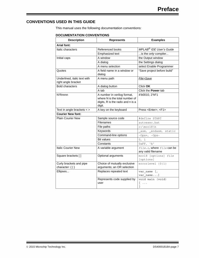
CONVENTIONS USED IN THIS GUIDE
This manual uses the following documentation conventions:
DOCUMENTATION CONVENTIONS
Description Represents Examples
Arial font:
Italic characters Referenced books MPLAB® IDE User’s Guide
Emphasized text ...is the only compiler...
Initial caps A window the Output window
A dialog the Settings dialog
A menu selection select Enable Programmer
Quotes A field name in a window or dialog
“Save project before build”
Underlined, italic text with right angle bracket
A menu path File>Save
Bold characters A dialog button Click OK
A tab Click the Power tab
N‘Rnnnn A number in verilog format, where N is the total number of digits, R is the radix and n is a digit.
4‘b0010, 2‘hF1
Text in angle brackets < > A key on the keyboard Press <Enter>, <F1>
Courier New font:
Plain Courier New Sample source code #define START
Filenames autoexec.bat
File paths c:\mcc18\h
Keywords _asm, _endasm, static
Command-line options -Opa+, -Opa-
Bit values 0, 1
Constants 0xFF, ‘A’
Italic Courier New A variable argument file.o, where file can be any valid filename
Square brackets [ ] Optional arguments mcc18 [options] file [options]
Curly brackets and pipe character: { | }
Choice of mutually exclusive arguments; an OR selection
errorlevel {0|1}
Ellipses... Replaces repeated text var_name [, var_name...]
Represents code supplied by user
void main (void){ ...}
2015 Microchip Technology Inc. DS40001818A-page 7
Low-Cost mTouch® Evaluation Kit User’s Guide
WARRANTY REGISTRATION
Please complete the enclosed Warranty Registration Card and mail it promptly. Sending in the Warranty Registration Card entitles users to receive new product updates. Interim software releases are available at the Microchip website.
RECOMMENDED READING
This user’s guide describes how to use the Low-Cost mTouch® Evaluation Kit. Other useful documents are listed below. The following Microchip documents are available and recommended as supplemental reference resources.
http://www.microchip.com
PIC16LF1554/1559 20-Pin Flash, 8-Bit Microcontroller Data Sheet (DS40001761)
This data sheet provides detailed information regarding the PIC16LF1559.
DS40001818A-page 8 2015 Microchip Technology Inc.
Preface
THE MICROCHIP WEBSITE
Microchip provides online support via our website at www.microchip.com. This website is used as a means to make files and information easily available to customers. Acces-sible by using your favorite Internet browser, the website contains the following infor-mation:
• Product Support – Data sheets and errata, application notes and sample programs, design resources, user’s guides and hardware support documents, latest software releases and archived software
• General Technical Support – Frequently Asked Questions (FAQs), technical support requests, online discussion groups, Microchip consultant program member listing
• Business of Microchip – Product selector and ordering guides, latest Microchip press releases, listing of seminars and events, listings of Microchip sales offices, distributors and factory representatives
DEVELOPMENT SYSTEMS CUSTOMER CHANGE NOTIFICATION SERVICE
Microchip’s customer notification service helps keep customers current on Microchip products. Subscribers will receive e-mail notification whenever there are changes, updates, revisions or errata related to a specified product family or development tool of interest.
To register, access the Microchip website at www.microchip.com, click on Customer Change Notification and follow the registration instructions.
The Development Systems product group categories are:
• Compilers – The latest information on Microchip C compilers, assemblers, linkers and other language tools. These include all MPLAB C compilers; all MPLAB assemblers (including MPASM™ assembler); all MPLAB linkers (including MPLINK™ object linker); and all MPLAB librarians (including MPLIB™ object librarian).
• Emulators – The latest information on Microchip in-circuit emulators.This includes the MPLAB REAL ICE™ and MPLAB ICE 2000 in-circuit emulators.
• In-Circuit Debuggers – The latest information on the Microchip in-circuit debuggers. This includes MPLAB ICD 3 in-circuit debuggers and PICkit™ 3 debug express.
• MPLAB® IDE – The latest information on Microchip MPLAB IDE, the Windows® Integrated Development Environment for development systems tools. This list is focused on the MPLAB IDE, MPLAB IDE Project Manager, MPLAB Editor and MPLAB SIM simulator, as well as general editing and debugging features.
• Programmers – The latest information on Microchip programmers. These include production programmers such as MPLAB REAL ICE in-circuit emulator, MPLAB ICD 3 in-circuit debugger and MPLAB PM3 device programmers. Also included are nonproduction development programmers such as PICSTART® Plus and PICkit 2 and 3.
2015 Microchip Technology Inc. DS40001818A-page 9
Low-Cost mTouch® Evaluation Kit User’s Guide
CUSTOMER SUPPORT
Users of Microchip products can receive assistance through several channels:
• Distributor or Representative
• Local Sales Office
• Field Application Engineer (FAE)
• Technical Support
Customers should contact their distributor, representative or field application engineer (FAE) for support. Local sales offices are also available to help customers. A listing of sales offices and locations is included in the back of this document.
Technical support is available through the website at:
http://www.microchip.com/support.
REVISION HISTORY
Revision A (November 2015)
Initial release of this document.
DS40001818A-page 10 2015 Microchip Technology Inc.
LOW-COST mTouch® EVALUATION KITUSER’S GUIDE
Chapter 1. Low-Cost mTouch® Evaluation Kit Overview
1.1 INTRODUCTION
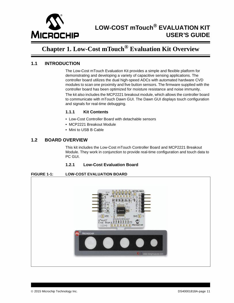
The Low-Cost mTouch Evaluation Kit provides a simple and flexible platform for demonstrating and developing a variety of capacitive sensing applications. The controller board utilizes the dual high-speed ADCs with automated hardware CVD modules to scan one proximity and five button sensors. The firmware supplied with the controller board has been optimized for moisture resistance and noise immunity.
The kit also includes the MCP2221 breakout module, which allows the controller board to communicate with mTouch Dawn GUI. The Dawn GUI displays touch configuration and signals for real-time debugging.
1.1.1 Kit Contents
• Low-Cost Controller Board with detachable sensors
• MCP2221 Breakout Module
• Mini to USB B Cable
1.2 BOARD OVERVIEW
This kit includes the Low-Cost mTouch Controller Board and MCP2221 Breakout Module. They work in conjunction to provide real-time configuration and touch data to PC GUI.
1.2.1 Low-Cost Evaluation Board
FIGURE 1-1: LOW-COST EVALUATION BOARD
®
TM
®
2015 Microchip Technology Inc. DS40001818A-page 11
Low-Cost mTouch® Evaluation Kit User’s Guide
Figure 1-1 shows the Low-Cost mTouch Evaluation board. It includes a proximity loop sensor, five touch button sensors, six LEDs, an ICSP™ header and PICkit™ Serial interface.
The default firmware scans the proximity and touch buttons periodically, and uses the LEDs to indicate the proximity and button state. If a proximity or touch event is detected, the corresponding LED will be lit. An I2C interface is also implemented to communicate with a host system through the header marked with “PICkit SA”, which accommodates the PICkit Serial Analyzer pin-out. This feature allows the system not only to report its sensor data in real-time, but to be configured by a host device as well.
1.2.2 MCP2221 Breakout Module
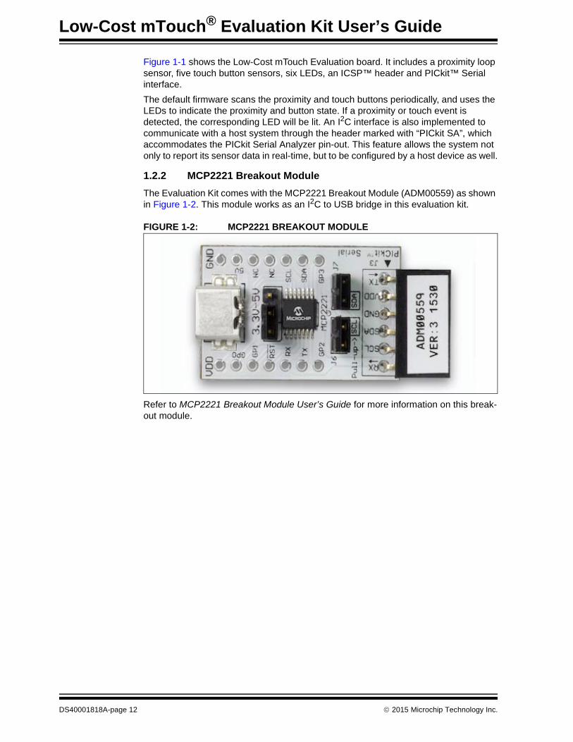
The Evaluation Kit comes with the MCP2221 Breakout Module (ADM00559) as shown in Figure 1-2. This module works as an I2C to USB bridge in this evaluation kit.
FIGURE 1-2: MCP2221 BREAKOUT MODULE
Refer to MCP2221 Breakout Module User’s Guide for more information on this break-out module.
DS40001818A-page 12 2015 Microchip Technology Inc.
Low-Cost mTouch® Evaluation Kit Overview
1.3 BOARD SETUP
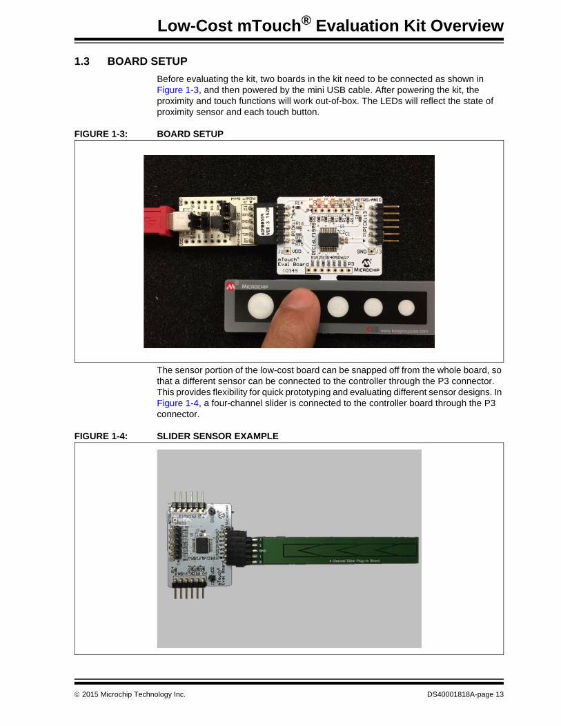
Before evaluating the kit, two boards in the kit need to be connected as shown in Figure 1-3, and then powered by the mini USB cable. After powering the kit, the proximity and touch functions will work out-of-box. The LEDs will reflect the state of proximity sensor and each touch button.
FIGURE 1-3: BOARD SETUP
The sensor portion of the low-cost board can be snapped off from the whole board, so that a different sensor can be connected to the controller through the P3 connector. This provides flexibility for quick prototyping and evaluating different sensor designs. In Figure 1-4, a four-channel slider is connected to the controller board through the P3 connector.
FIGURE 1-4: SLIDER SENSOR EXAMPLE
® ®
TM
®
TM
2015 Microchip Technology Inc. DS40001818A-page 13
Low-Cost mTouch® Evaluation Kit User’s Guide
NOTES:
DS40001818A-page 14 2015 Microchip Technology Inc.
LOW-COST mTouch® EVALUATION KITUSER’S GUIDE
Chapter 2. Communication and System Register
2.1 INTRODUCTION
The default firmware on the Low-cost Evaluation Board communicates with host system through a register-based I2C communication protocol.
2.1.1 mTouch I2C communication protocols
The default I2C slave address for this evaluation board is 0x28 (7-bit address). The evaluation board supports the following protocols: Read Byte, Write Byte, Read Block, and Write Block. Please note that the system register referred in this document is on the firmware level, not the PIC® microcontroller registers in the data sheet.
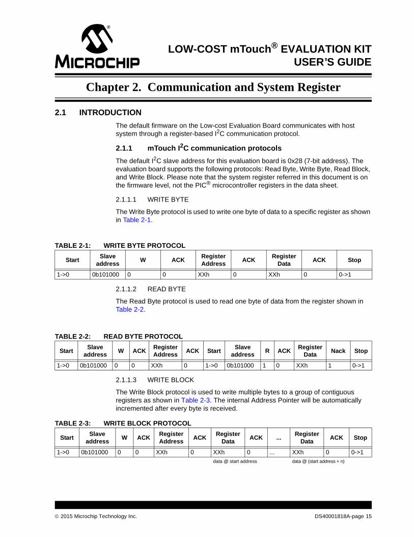
2.1.1.1 WRITE BYTE
The Write Byte protocol is used to write one byte of data to a specific register as shown in Table 2-1.
2.1.1.2 READ BYTE
The Read Byte protocol is used to read one byte of data from the register shown in Table 2-2.
2.1.1.3 WRITE BLOCK
The Write Block protocol is used to write multiple bytes to a group of contiguous registers as shown in Table 2-3. The internal Address Pointer will be automatically incremented after every byte is received.
TABLE 2-1: WRITE BYTE PROTOCOL
StartSlave
addressW ACK
Register Address
ACKRegister
DataACK Stop
1->0 0b101000 0 0 XXh 0 XXh 0 0->1
TABLE 2-2: READ BYTE PROTOCOL
StartSlave
addressW ACK
Register Address
ACK StartSlave
addressR ACK
Register Data
Nack Stop
1->0 0b101000 0 0 XXh 0 1->0 0b101000 1 0 XXh 1 0->1
TABLE 2-3: WRITE BLOCK PROTOCOL
StartSlave
addressW ACK
Register Address
ACKRegister
DataACK ...
Register Data
ACK Stop
1->0 0b101000 0 0 XXh 0 XXh 0 ... XXh 0 0->1
data @ start address data @ (start address + n)
2015 Microchip Technology Inc. DS40001818A-page 15
Low-Cost mTouch® Evaluation Kit User’s Guide
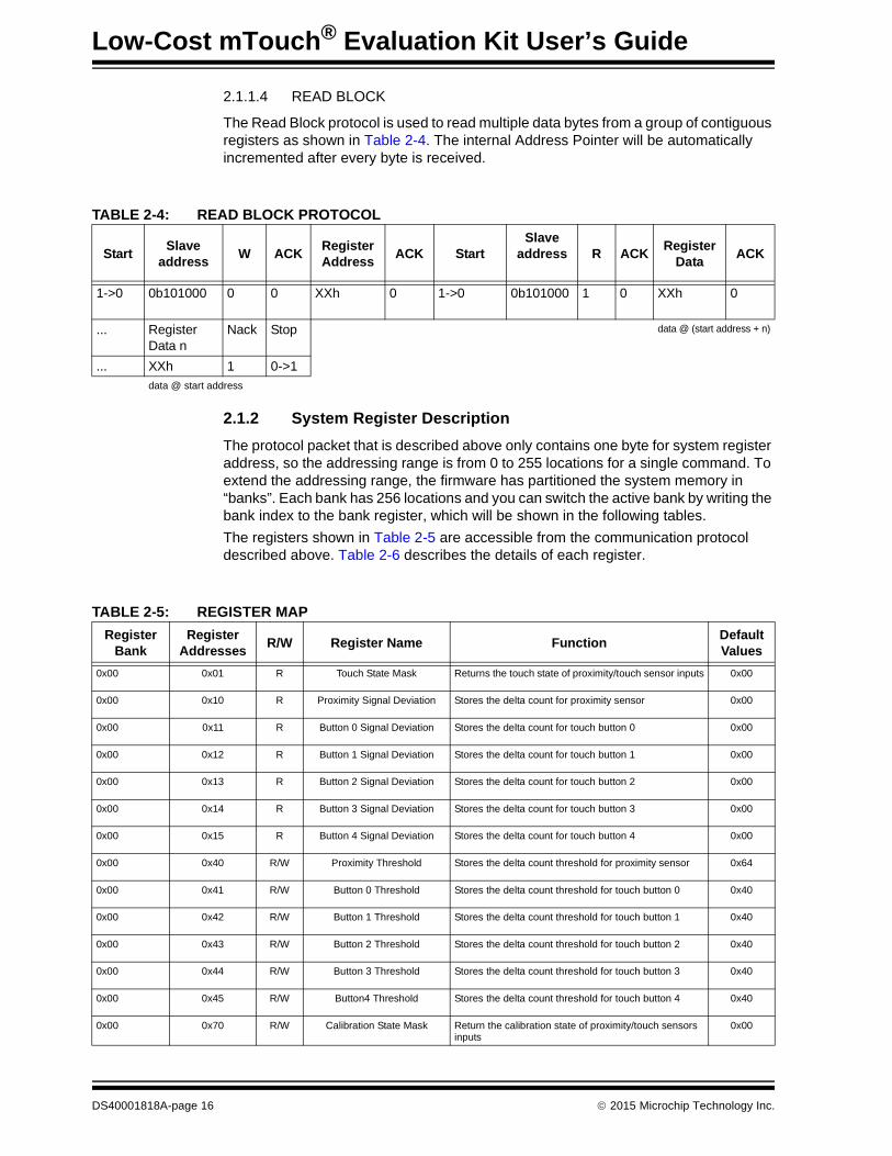
2.1.1.4 READ BLOCK
The Read Block protocol is used to read multiple data bytes from a group of contiguous registers as shown in Table 2-4. The internal Address Pointer will be automatically incremented after every byte is received.
2.1.2 System Register Description
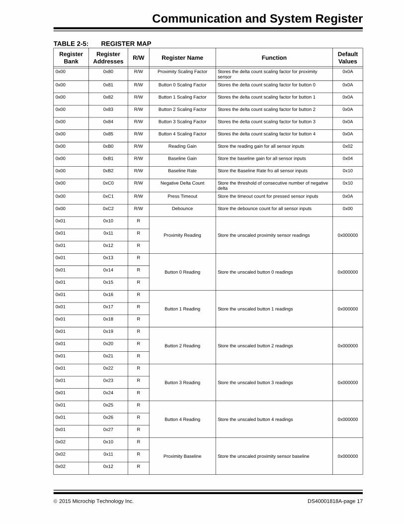
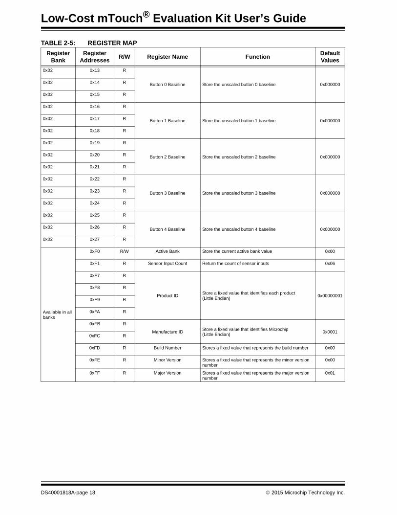
The protocol packet that is described above only contains one byte for system register address, so the addressing range is from 0 to 255 locations for a single command. To extend the addressing range, the firmware has partitioned the system memory in “banks”. Each bank has 256 locations and you can switch the active bank by writing the bank index to the bank register, which will be shown in the following tables.
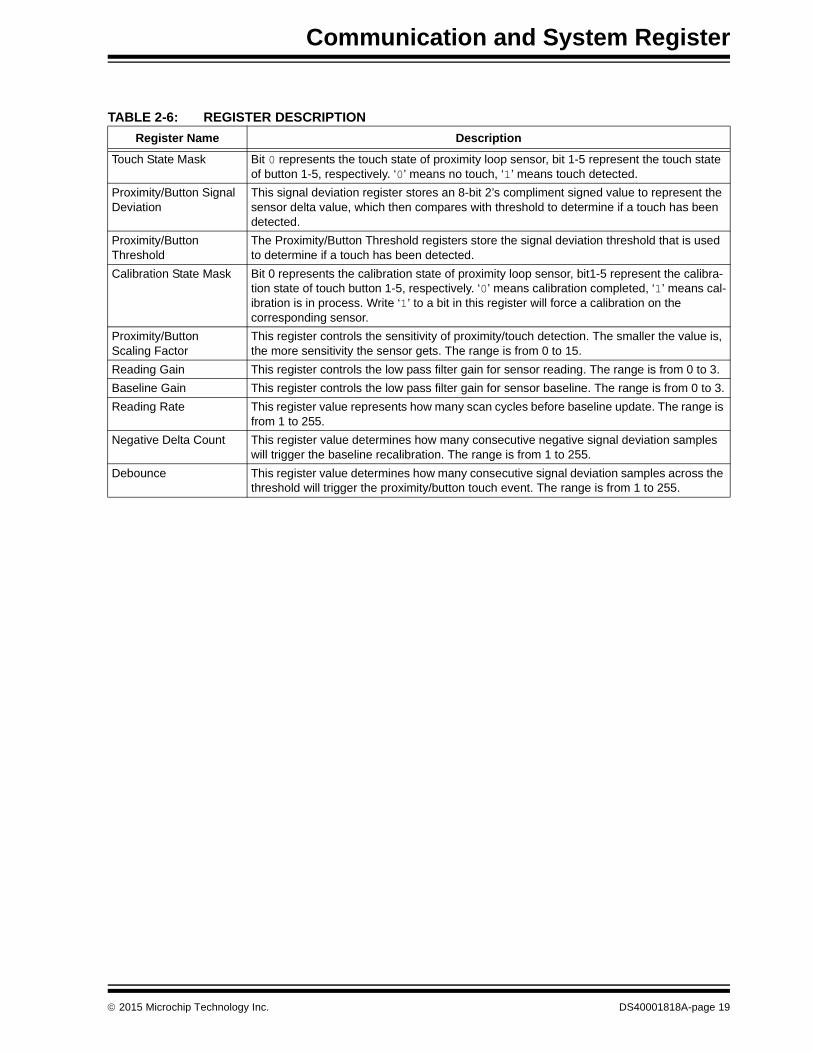
The registers shown in Table 2-5 are accessible from the communication protocol described above. Table 2-6 describes the details of each register.
TABLE 2-4: READ BLOCK PROTOCOL
StartSlave
addressW ACK
Register Address
ACK StartSlave
address R ACKRegister
DataACK
1->0 0b101000 0 0 XXh 0 1->0 0b101000 1 0 XXh 0
... Register Data n
Nack Stop data @ (start address + n)
... XXh 1 0->1
data @ start address
TABLE 2-5: REGISTER MAP
Register Bank
Register Addresses
R/W Register Name FunctionDefault Values
0x00 0x01 R Touch State Mask Returns the touch state of proximity/touch sensor inputs 0x00
0x00 0x10 R Proximity Signal Deviation Stores the delta count for proximity sensor 0x00
0x00 0x11 R Button 0 Signal Deviation Stores the delta count for touch button 0 0x00
0x00 0x12 R Button 1 Signal Deviation Stores the delta count for touch button 1 0x00
0x00 0x13 R Button 2 Signal Deviation Stores the delta count for touch button 2 0x00
0x00 0x14 R Button 3 Signal Deviation Stores the delta count for touch button 3 0x00
0x00 0x15 R Button 4 Signal Deviation Stores the delta count for touch button 4 0x00
0x00 0x40 R/W Proximity Threshold Stores the delta count threshold for proximity sensor 0x64
0x00 0x41 R/W Button 0 Threshold Stores the delta count threshold for touch button 0 0x40
0x00 0x42 R/W Button 1 Threshold Stores the delta count threshold for touch button 1 0x40
0x00 0x43 R/W Button 2 Threshold Stores the delta count threshold for touch button 2 0x40
0x00 0x44 R/W Button 3 Threshold Stores the delta count threshold for touch button 3 0x40
0x00 0x45 R/W Button4 Threshold Stores the delta count threshold for touch button 4 0x40
0x00 0x70 R/W Calibration State Mask Return the calibration state of proximity/touch sensors inputs
0x00
DS40001818A-page 16 2015 Microchip Technology Inc.
Communication and System Register
0x00 0x80 R/W Proximity Scaling Factor Stores the delta count scaling factor for proximity sensor
0x0A
0x00 0x81 R/W Button 0 Scaling Factor Stores the delta count scaling factor for button 0 0x0A
0x00 0x82 R/W Button 1 Scaling Factor Stores the delta count scaling factor for button 1 0x0A
0x00 0x83 R/W Button 2 Scaling Factor Stores the delta count scaling factor for button 2 0x0A
0x00 0x84 R/W Button 3 Scaling Factor Stores the delta count scaling factor for button 3 0x0A
0x00 0x85 R/W Button 4 Scaling Factor Stores the delta count scaling factor for button 4 0x0A
0x00 0xB0 R/W Reading Gain Store the reading gain for all sensor inputs 0x02
0x00 0xB1 R/W Baseline Gain Store the baseline gain for all sensor inputs 0x04
0x00 0xB2 R/W Baseline Rate Store the Baseline Rate fro all sensor inputs 0x10
0x00 0xC0 R/W Negative Delta Count Store the threshold of consecutive number of negative delta
0x10
0x00 0xC1 R/W Press Timeout Store the timeout count for pressed sensor inputs 0x0A
0x00 0xC2 R/W Debounce Store the debounce count for all sensor inputs 0x00
0x01 0x10 R
Proximity Reading Store the unscaled proximity sensor readings 0x0000000x01 0x11 R
0x01 0x12 R
0x01 0x13 R
Button 0 Reading Store the unscaled button 0 readings 0x0000000x01 0x14 R
0x01 0x15 R
0x01 0x16 R
Button 1 Reading Store the unscaled button 1 readings 0x0000000x01 0x17 R
0x01 0x18 R
0x01 0x19 R
Button 2 Reading Store the unscaled button 2 readings 0x0000000x01 0x20 R
0x01 0x21 R
0x01 0x22 R
Button 3 Reading Store the unscaled button 3 readings 0x0000000x01 0x23 R
0x01 0x24 R
0x01 0x25 R
Button 4 Reading Store the unscaled button 4 readings 0x0000000x01 0x26 R
0x01 0x27 R
0x02 0x10 R
Proximity Baseline Store the unscaled proximity sensor baseline 0x0000000x02 0x11 R
0x02 0x12 R
TABLE 2-5: REGISTER MAP
Register Bank
Register Addresses
R/W Register Name FunctionDefault Values
2015 Microchip Technology Inc. DS40001818A-page 17
Low-Cost mTouch® Evaluation Kit User’s Guide
0x02 0x13 R
Button 0 Baseline Store the unscaled button 0 baseline 0x0000000x02 0x14 R
0x02 0x15 R
0x02 0x16 R
Button 1 Baseline Store the unscaled button 1 baseline 0x0000000x02 0x17 R
0x02 0x18 R
0x02 0x19 R
Button 2 Baseline Store the unscaled button 2 baseline 0x0000000x02 0x20 R
0x02 0x21 R
0x02 0x22 R
Button 3 Baseline Store the unscaled button 3 baseline 0x0000000x02 0x23 R
0x02 0x24 R
0x02 0x25 R
Button 4 Baseline Store the unscaled button 4 baseline 0x0000000x02 0x26 R
0x02 0x27 R
Available in all banks
0xF0 R/W Active Bank Store the current active bank value 0x00
0xF1 R Sensor Input Count Return the count of sensor inputs 0x06
0xF7 R
Product IDStore a fixed value that identifies each product(Little Endian)
0x00000001
0xF8 R
0xF9 R
0xFA R
0xFB R
Manufacture IDStore a fixed value that identifies Microchip(Little Endian)
0x00010xFC R
0xFD R Build Number Stores a fixed value that represents the build number 0x00
0xFE R Minor Version Stores a fixed value that represents the minor version number
0x00
0xFF R Major Version Stores a fixed value that represents the major version number
0x01
TABLE 2-5: REGISTER MAP
Register Bank
Register Addresses
R/W Register Name FunctionDefault Values
DS40001818A-page 18 2015 Microchip Technology Inc.
Communication and System Register
TABLE 2-6: REGISTER DESCRIPTION
Register Name Description
Touch State Mask Bit 0 represents the touch state of proximity loop sensor, bit 1-5 represent the touch state of button 1-5, respectively. ‘0’ means no touch, ‘1’ means touch detected.
Proximity/Button Signal Deviation
This signal deviation register stores an 8-bit 2’s compliment signed value to represent the sensor delta value, which then compares with threshold to determine if a touch has been detected.
Proximity/Button Threshold
The Proximity/Button Threshold registers store the signal deviation threshold that is used to determine if a touch has been detected.
Calibration State Mask Bit 0 represents the calibration state of proximity loop sensor, bit1-5 represent the calibra-tion state of touch button 1-5, respectively. ‘0’ means calibration completed, ‘1’ means cal-ibration is in process. Write ‘1’ to a bit in this register will force a calibration on the corresponding sensor.
Proximity/Button Scaling Factor
This register controls the sensitivity of proximity/touch detection. The smaller the value is, the more sensitivity the sensor gets. The range is from 0 to 15.
Reading Gain This register controls the low pass filter gain for sensor reading. The range is from 0 to 3.
Baseline Gain This register controls the low pass filter gain for sensor baseline. The range is from 0 to 3.
Reading Rate This register value represents how many scan cycles before baseline update. The range is from 1 to 255.
Negative Delta Count This register value determines how many consecutive negative signal deviation samples will trigger the baseline recalibration. The range is from 1 to 255.
Debounce This register value determines how many consecutive signal deviation samples across the threshold will trigger the proximity/button touch event. The range is from 1 to 255.
2015 Microchip Technology Inc. DS40001818A-page 19
LOW-COST mTouch® EVALUATION KITUSER’S GUIDE
Chapter 3. Work with mTouch® Dawn GUI
The mTouch Dawn GUI can be installed on a Windows-based computer with a USB port, in order to further evaluate the performance and features of the PIC16LF1559 touch solution. The MCP2221 board works as the I2C host, polling data from the PIC16LF1559 evaluation board at a fixed time interval, communicating then with the Dawn GUI through USB communication.
3.1 DAWN GUI INSTALLATION
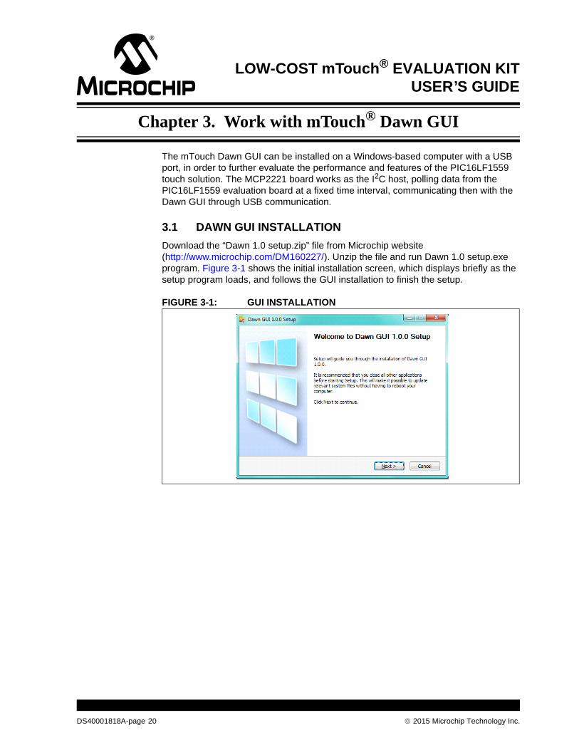
Download the “Dawn 1.0 setup.zip” file from Microchip website (http://www.microchip.com/DM160227/). Unzip the file and run Dawn 1.0 setup.exe program. Figure 3-1 shows the initial installation screen, which displays briefly as the setup program loads, and follows the GUI installation to finish the setup.
FIGURE 3-1: GUI INSTALLATION
DS40001818A-page 20 2015 Microchip Technology Inc.
Work with mTouch® Dawn GUI
3.2 GUI OVERVIEW
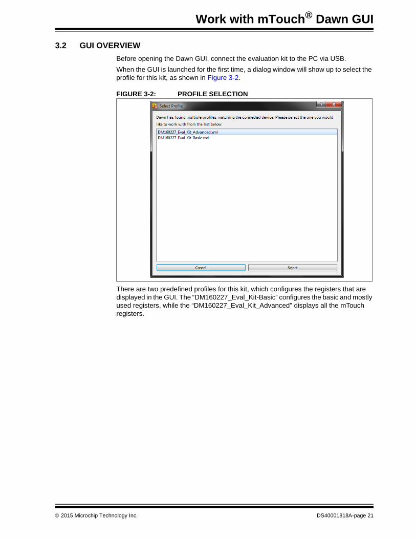
Before opening the Dawn GUI, connect the evaluation kit to the PC via USB.
When the GUI is launched for the first time, a dialog window will show up to select the profile for this kit, as shown in Figure 3-2.
FIGURE 3-2: PROFILE SELECTION
There are two predefined profiles for this kit, which configures the registers that are displayed in the GUI. The “DM160227_Eval_Kit-Basic” configures the basic and mostly used registers, while the “DM160227_Eval_Kit_Advanced” displays all the mTouch registers.
2015 Microchip Technology Inc. DS40001818A-page 21
Low-Cost mTouch® Evaluation Kit User’s Guide
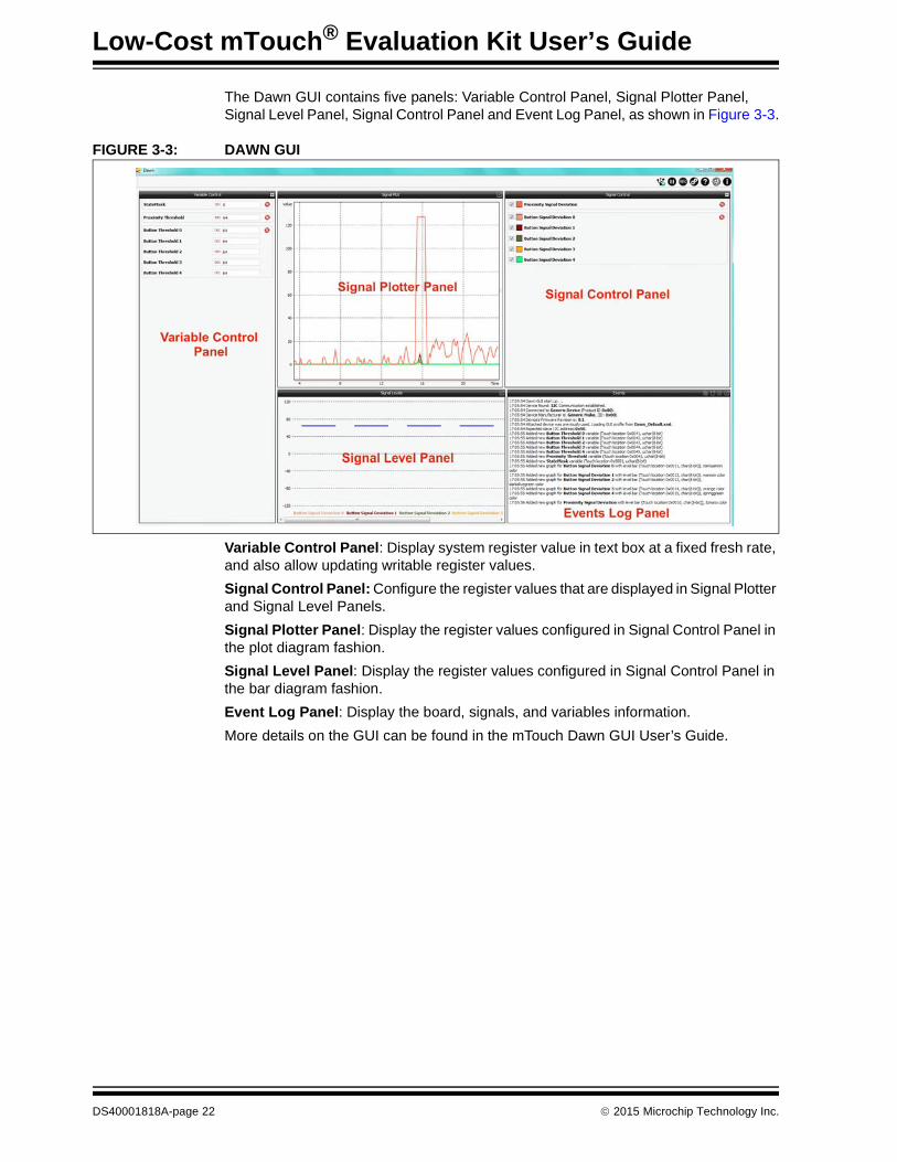
The Dawn GUI contains five panels: Variable Control Panel, Signal Plotter Panel, Signal Level Panel, Signal Control Panel and Event Log Panel, as shown in Figure 3-3.
FIGURE 3-3: DAWN GUI
Variable Control Panel: Display system register value in text box at a fixed fresh rate, and also allow updating writable register values.
Signal Control Panel: Configure the register values that are displayed in Signal Plotter and Signal Level Panels.
Signal Plotter Panel: Display the register values configured in Signal Control Panel in the plot diagram fashion.
Signal Level Panel: Display the register values configured in Signal Control Panel in the bar diagram fashion.
Event Log Panel: Display the board, signals, and variables information.
More details on the GUI can be found in the mTouch Dawn GUI User’s Guide.
DS40001818A-page 22 2015 Microchip Technology Inc.
Work with mTouch® Dawn GUI
NOTES:
2015 Microchip Technology Inc. DS40001818A-page 23
LOW-COST mTouch® EVALUATION KITUSER’S GUIDE
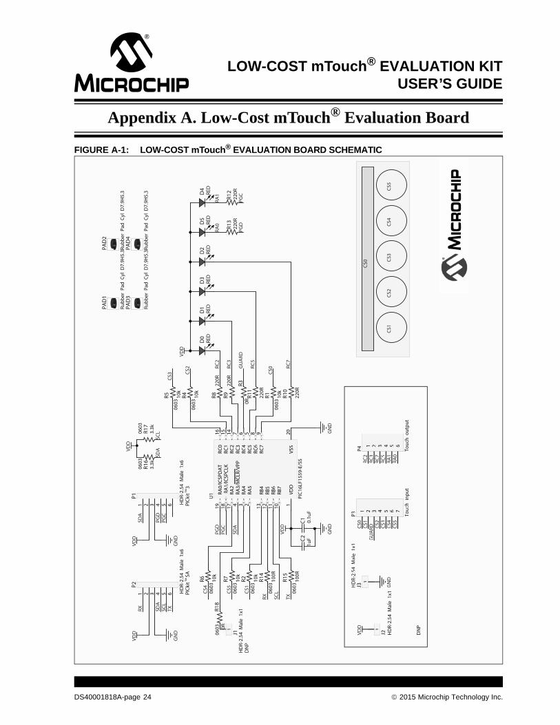
Appendix A. Low-Cost mTouch® Evaluation Board
FIGURE A-1: LOW-COST mTouch® EVALUATION BOARD SCHEMATIC
VDD
PGD
PGC
GN
D
VDD
0.1u
FC1
GN
D
GU
ARD
TX
SDA
CS3
RX SCL
VDD
GN
D
PGC
PGD
SDA
VDD
VDD
GN
D
PGD
PGC
SDA
SCL
SDA
SCL
TXRX
CS0
1
HD
R-2.
54 M
ale
1x1
J1 VDD
GN
DCS
1CS
2CS
3CS
4CS
5
1uFC2
1 2 3 4 5 6 7
P3 Touc
h in
put
CS0
CS1
CS2
CS3
CS4
CS5
GU
ARD
CS0
CS1
CS2
CS4
CS5
1
HD
R-2.
54 M
ale
1x1
J2
1
HD
R-2.
54 M
ale
1x1
J3
1 2 3 4 5 6
P4 Touc
h ou
tput
RC2
RC3
RC5
RC7
RC2
RC3
RC7
RC5
RA1
RA0
RA1
RA0
VDD
1
RA5
2RA
43
RA3/
MCL
R/VP
P4
RC5
5RC
46
RC3
7
RC6
8
RC7
9
RB7
10RB
611
RB5
12RB
413
RC2
14RC
115
RC0
16
RA2
17RA
1/IC
SPCL
K18
RA0/
ICSP
DA
T19
VSS
20VD
D
RA5
RA4
RA3/
MCL
R/VP
P
RC5
RC4
RC3
RC6
RC7
RB7
RB6
RB5
RB4
RC2
RC1
RC0
RA2
RA1/
ICSP
CLK
RA0/
ICSP
DA
T
VSS
U1
PIC1
6LF1
559-
E/SS
10k
0603
R6 10k
0603
R7 10k
0603
R2
10k
0603
R5 10k
0603
R4 10k
0603
R110
0R06
03
R14
100R
0603
R15
220R
R8
220R
R9 220R
R11
220R
R10
220R
R13
220R
R12
0RR3
3.3k
0603
R16
3.3k
0603
R17
1 2 3 4 5 6 HD
R-2.
54 M
ale
1x6
PICk
it S
A
P21 2 3 4 5 6 H
DR-
2.54
Mal
e 1x
6PI
Ckit
3
P1
VDD
GN
D
1 2 3 4 5 6 7
P3 Touc
hin
put
CS0
CS1
CS2
CS3
CS4
CS5
GU
ARD
1
HD
R-2.
54M
ale
1x1
J2
1
HD
R-2.
54M
ale
1x1
J3
1 2 3 4 5 6
P4 Touc
hou
tput
RC2
RC3
RC7
RC5
RA1
RA0
DN
P
DN
P
0R06
03R1
8
RED
D0
RED
D1
RED
D3
RED
D2
RED
D5
RED
D4
Rubb
er P
ad C
yl D
7.9H
5.3
PAD1
Rubb
er P
ad C
yl D
7.9H
5.3
PAD2
Rubb
er P
ad C
yl D
7.9H
5.3
PAD3
Rubb
er P
ad C
yl D
7.9H
5.3
PAD4
TMTM
DS40001818A-page 24 2015 Microchip Technology Inc.
Low-Cost mTouch® Evaluation Board
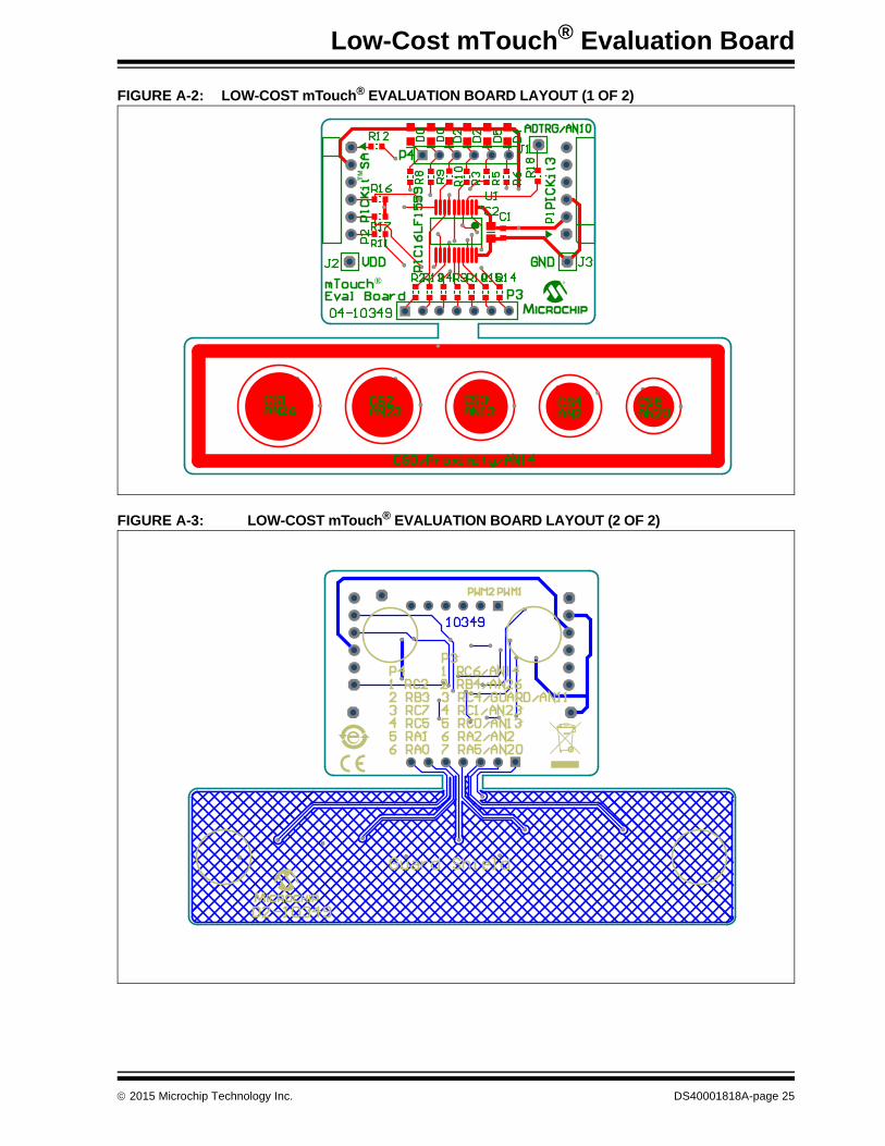
FIGURE A-2: LOW-COST mTouch® EVALUATION BOARD LAYOUT (1 OF 2)
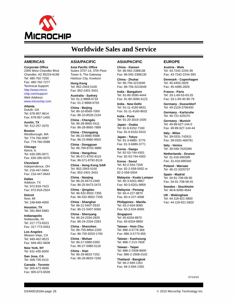
FIGURE A-3: LOW-COST mTouch® EVALUATION BOARD LAYOUT (2 OF 2)
®
TM
2015 Microchip Technology Inc. DS40001818A-page 25
DS40001818A-page 26 2015 Microchip Technology Inc.
AMERICASCorporate Office2355 West Chandler Blvd.Chandler, AZ 85224-6199Tel: 480-792-7200 Fax: 480-792-7277Technical Support: http://www.micro-chip.com/supportWeb Address: www.microchip.com
AtlantaDuluth, GA Tel: 678-957-9614 Fax: 678-957-1455
Austin, TXTel: 512-257-3370
BostonWestborough, MA Tel: 774-760-0087 Fax: 774-760-0088
ChicagoItasca, IL Tel: 630-285-0071 Fax: 630-285-0075
ClevelandIndependence, OH Tel: 216-447-0464 Fax: 216-447-0643
DallasAddison, TX Tel: 972-818-7423 Fax: 972-818-2924
DetroitNovi, MI Tel: 248-848-4000
Houston, TX Tel: 281-894-5983
IndianapolisNoblesville, IN Tel: 317-773-8323Fax: 317-773-5453
Los AngelesMission Viejo, CA Tel: 949-462-9523 Fax: 949-462-9608
New York, NY Tel: 631-435-6000
San Jose, CA Tel: 408-735-9110
Canada - TorontoTel: 905-673-0699 Fax: 905-673-6509
ASIA/PACIFICAsia Pacific OfficeSuites 3707-14, 37th FloorTower 6, The GatewayHarbour City, Kowloon
Hong KongTel: 852-2943-5100Fax: 852-2401-3431
Australia - SydneyTel: 61-2-9868-6733Fax: 61-2-9868-6755
China - BeijingTel: 86-10-8569-7000 Fax: 86-10-8528-2104
China - ChengduTel: 86-28-8665-5511Fax: 86-28-8665-7889
China - ChongqingTel: 86-23-8980-9588Fax: 86-23-8980-9500
China - DongguanTel: 86-769-8702-9880
China - HangzhouTel: 86-571-8792-8115 Fax: 86-571-8792-8116
China - Hong Kong SARTel: 852-2943-5100 Fax: 852-2401-3431
China - NanjingTel: 86-25-8473-2460Fax: 86-25-8473-2470
China - QingdaoTel: 86-532-8502-7355Fax: 86-532-8502-7205
China - ShanghaiTel: 86-21-5407-5533 Fax: 86-21-5407-5066
China - ShenyangTel: 86-24-2334-2829Fax: 86-24-2334-2393
China - ShenzhenTel: 86-755-8864-2200 Fax: 86-755-8203-1760
China - WuhanTel: 86-27-5980-5300Fax: 86-27-5980-5118
China - XianTel: 86-29-8833-7252Fax: 86-29-8833-7256
ASIA/PACIFICChina - XiamenTel: 86-592-2388138 Fax: 86-592-2388130
China - ZhuhaiTel: 86-756-3210040 Fax: 86-756-3210049
India - BangaloreTel: 91-80-3090-4444 Fax: 91-80-3090-4123
India - New DelhiTel: 91-11-4160-8631Fax: 91-11-4160-8632
India - PuneTel: 91-20-3019-1500
Japan - OsakaTel: 81-6-6152-7160 Fax: 81-6-6152-9310
Japan - TokyoTel: 81-3-6880- 3770 Fax: 81-3-6880-3771
Korea - DaeguTel: 82-53-744-4301Fax: 82-53-744-4302
Korea - SeoulTel: 82-2-554-7200Fax: 82-2-558-5932 or 82-2-558-5934
Malaysia - Kuala LumpurTel: 60-3-6201-9857Fax: 60-3-6201-9859
Malaysia - PenangTel: 60-4-227-8870Fax: 60-4-227-4068
Philippines - ManilaTel: 63-2-634-9065Fax: 63-2-634-9069
SingaporeTel: 65-6334-8870Fax: 65-6334-8850
Taiwan - Hsin ChuTel: 886-3-5778-366Fax: 886-3-5770-955
Taiwan - KaohsiungTel: 886-7-213-7828
Taiwan - TaipeiTel: 886-2-2508-8600 Fax: 886-2-2508-0102
Thailand - BangkokTel: 66-2-694-1351Fax: 66-2-694-1350
EUROPEAustria - WelsTel: 43-7242-2244-39Fax: 43-7242-2244-393
Denmark - CopenhagenTel: 45-4450-2828 Fax: 45-4485-2829
France - ParisTel: 33-1-69-53-63-20 Fax: 33-1-69-30-90-79
Germany - DusseldorfTel: 49-2129-3766400
Germany - KarlsruheTel: 49-721-625370
Germany - MunichTel: 49-89-627-144-0 Fax: 49-89-627-144-44
Italy - Milan Tel: 39-0331-742611 Fax: 39-0331-466781
Italy - VeniceTel: 39-049-7625286
Netherlands - DrunenTel: 31-416-690399 Fax: 31-416-690340
Poland - WarsawTel: 48-22-3325737
Spain - MadridTel: 34-91-708-08-90Fax: 34-91-708-08-91
Sweden - StockholmTel: 46-8-5090-4654
UK - WokinghamTel: 44-118-921-5800Fax: 44-118-921-5820
Worldwide Sales and Service
07/14/15


![PEB08 USER GUIDE - insem.co.krinsem.co.kr/data/PEB08/PEB08_USER_GUIDE.pdf · PEB08 User’s Guide Pic Evaluation Board 08bits Switch [Switch [JP44]JP44]JP44] ---- mTouch 혹은 해당](https://img.pdfslide.us/doc/110x75/5d15ece488c993fd118db628/peb08-user-guide-insemco-peb08-users-guide-pic-evaluation-board-08bits.jpg)


