Embed Size (px)
Citation preview

1
LOW COST FIBREGLASS GO-KART
LIEW YI HUI
UNIVERSITI TUNKU ABDUL RAHMAN

ii
ii
DECLARATION
I hereby declare that this project report is based on my original work except for
citations and quotations which have been duly acknowledged. I also declare that it
has not been previously and concurrently submitted for any other degree or award at
UTAR or other institutions.
Signature : _________________________
Name : Liew Yi Hui
ID No. : 07UEB05782
Date : 20 April 2011

iii
iii
APPROVAL FOR SUBMISSION
I certify that this project report entitled “LOW COST FIBREGLASS GO-KART”
was prepared by LIEW YI HUI has met the required standard for submission in
partial fulfilment of the requirements for the award of Bachelor of Engineering
(Hons.) Mechanical Engineering at Universiti Tunku Abdul Rahman.
Approved by,
Signature : _________________________
Supervisor : Mr. Wong Hong Mun
Date : _________________________

iv
iv
The copyright of this report belongs to the author under the terms of the
copyright Act 1987 as qualified by Intellectual Property Policy of University Tunku
Abdul Rahman. Due acknowledgement shall always be made of the use of any
material contained in, or derived from, this report.
© 2011, Liew Yi Hui. All right reserved.

v
v
ACKNOWLEDGEMENTS
I would like to thank everyone who had contributed to the successful completion of
this project. I would like to express my gratitude to my research supervisor, Mr.
Wong Hong Mun for his invaluable advice, guidance and his enormous patience
throughout the development of the research.
In addition, I would also like to express my gratitude to my team partner who
had contributed so much effort in completing this project. Besides, I would like to
express my appreciation to all my friends and course mates who had provided me
information and guidance towards the completion of the project. Lastly, I would like
to thank my loving parent for their moral support and encouragement which helped
me to face every single obstruction positively.

vi
vi
LOW COST FIBREGLASS GO-KART
ABSTRACT
The purpose of this project was to develop a go-kart chassis by using the fibreglass
composites material. Prior to that, studies and researches have been done with the
purpose to understand the properties of the fibreglass composites material. Different
types of fibreglass material would have different properties and usages. Different
designs of the fibreglass-made go-kart chassis were developed and each of the
designs was simulated to find out the relevant information regarding the design. The
variations of the designs include the different in wall thickness of the chassis,
different type of reinforcements used and the vary design considerations as well. It is
known that when a go-kart chassis is loaded with a load of 70 kg or approximately
687 N, the bending deflection should be around a value of 5.229 mm. A suitable
design was selected by comparing the simulation data with the targeted value. The
selection was not only based on the results but the considerations such as the ease of
installation of components, ease of fabrication and the comfort level as well. Finally,
the prototype model was fabricated and experiment was carried out to verify the
design is complied with what has been simulated. It can be concluded that a
fibreglass-made go-kart chassis is feasible with the conditions of proper design and
appropriate selection of the fibreglass material used.

vii
vii
TABLE OF CONTENTS
DECLARATION ii
APPROVAL FOR SUBMISSION iii
ACKNOWLEDGEMENTS v
ABSTRACT vi
TABLE OF CONTENTS vii
LIST OF TABLES ix
LIST OF FIGURES x
LIST OF APPENDICES xiii
CHAPTER
1 INTRODUCTION 1
1.1 Background 1
1.2 Problem Statement 2
1.3 Aims and Objectives 2
1.4 Schedule 2
2 LITERATURE REVIEW 4
2.1 History of Go-Kart 4
2.2 Components of Go-kart 5
2.3 Applications of Fibreglass in Go-kart 11
2.4 Fibreglass 12
2.4.1 Advantages and Disadvantages of Fibreglass 13
2.4.2 Types of Fibreglass 13
2.4.3 Forms of Fibreglass 16

viii
viii
2.5 Polymer Matrix 18
2.6 Fabrication Process by Using Fibreglass Materials 22
2.7 Selection of the Types of Fibreglass and Resin 25
2.8 Concept of Design 26
2.9 Design Requirements 28
3 METHODOLOGY 30
3.1 Process Flow of the Project 30
3.2 Literature Review 32
3.3 Conceptual Design 32
3.4 Embodiment Design 33
3.5 CAD Modelling 33
3.6 Finite Element Analysis 34
3.7 Prototyping 34
4 RESULTS AND DISCUSSIONS 35
4.1 Design of Go-kart 35
4.1.1 First Kart Chassis Design 35
4.1.2 Second Kart Chassis Design 39
4.1.3 Third Kart Chassis Design 42
4.2 Fabrication of Go-kart Chassis 56
4.2.1 Fabrication Process of Go-kart Chassis 56
4.2.2 Highlighted Issues during the Fabrication Process 59
4.3 Comparison between Experimental and Simulation Data 61
4.4 Cost of Fabrication 64
5 CONCLUSION AND RECOMMENDATIONS 65
5.1 Conclusion 65
5.2 Recommendations 66
REFERENCES 67
APPENDICES 70

ix
ix
LIST OF TABLES
TABLE TITLE PAGE
2-1 Advantages and disadvantages of fibreglass 13
2-2 Typical composition of E-glass 14
2-3 Typical composition of S-glass 15
2-4 Typical composition of C-glass 16
2-5 The displacement obtained under a given load 28
4-1 Summary of the first design 38
4-2 Summary of the second design 40
4-3 Summary of the improved second design 42
4-4 Summary of the third kart chassis design 43
4-5 Table of force, displacement and torsional stiffness 53
4-6 Summary of the displacement obtained for each
version of design 55
4-7 Percentage difference between experimental
displacement and simulation data 62

x
x
LIST OF FIGURES
FIGURE TITLE PAGE
1-1 Gantt chart of the project 3
2-1 The first go-kart invented by Art Ingels. (IRGA,
1991) 4
2-2 Chassis of a go-kart (CIK-FIA, 2010) 6
2-3 Side view of a go-kart chassis (CIK-FIA, 2010) 6
2-4 Example of a slick tyre (Partsquip, 2010) 9
2-5 Example of a wet tyre (Sapiensman, 2010) 9
2-6 Simple steering knuckle system in go-kart (Go-
Kart Guru, 2008) 10
2-7 An example of continuous strand roving (GP
Impex, 2010) 16
2-8 An example of chopped strands (LBIE, 2009) 17
2-9 An example of chopped strands mat (QDC, S.L.,
2010) 17
2-10 An example of woven roving (DIYTrade, 2007) 18
2-11 The carbon-fibre monocoque chassis of MP4-12C
(McLaren Automotive, 2011) 26
2-12 An overhead view of the McLaren MP4-26
(McLaren F1, 2011) 27
2-13 The relationship between displacement and given
load 28
2-14 The force-deflection curve for a chassis testing
(Rileydynamics, 2011) 29

xi
xi
3-1 Flow chart of the project 31
4-1 The first design of the go-kart chassis 36
4-2 The wireframe model of the first go-kart chassis
design 36
4-3 Modified version of first kart chassis design 37
4-4 The wireframe model of the modified first go-kart
chassis design 38
4-5 The second design of the kart chassis 39
4-6 The simulation result for second design of kart
chassis 40
4-7 The kart chassis with 15 mm thickness 41
4-8 The third design of the go-kart chassis 42
4-9 The first version of third kart chassis design 44
4-10 The wireframe model for the first version of third
kart chassis design 44
4-11 The simulation result for the first version of third
kart chassis design 45
4-12 The second version of third kart chassis design 46
4-13 The wireframe model for the second version of
third kart chassis design 46
4-14 The simulation result for the second version of
third kart chassis design 47
4-15 The third version of third kart chassis design 48
4-16 The wireframe model for the third version of third
kart chassis design 48
4-17 The simulation result for the third version of third
kart chassis design 49
4-18 The forth version of third kart chassis design 50
4-19 The wireframe model for the forth version of third
kart chassis design 50

xii
xii
4-20 The simulation result for the forth version of third
kart chassis design 51
4-21 The fifth version of third kart chassis design 52
4-22 The wireframe model for the fifth version of third
kart chassis design 52
4-23 The simulation result for the fifth version of third
kart chassis design 53
4-24 The graph of torsional stiffness against force 54
4-25 The graph of displacement against force 54
4-26 The plywood moulding of the go-kart 56
4-27 The polystyrene foam moulding that form the
curvature part of the kart 56
4-28 Completed mould 57
4-29 Layering of fibreglass 57
4-30 Moulding of the inner wall 58
4-31 The reinforcement stripes on the chassis of the go-
kart 58
4-32 The damage caused on the polystyrene foam 59
4-33 Inconsistency in the thickness of the fibreglass mat 60
4-34 The air bubbles trapped inside the body of the
chassis 60
4-35 The strain gauge used to obtain the displacement
reading 61
4-36 Points taken during the experiment 62
4-37 The graph of percentage difference for each of the
points 63

xiii
xiii
LIST OF APPENDICES
APPENDIX TITLE PAGE
A History of Go-Kart 70
B Chassis 71
C Advantages and disadvantages of fibreglass 73
D Thermoplastic Matrix 75
E Dimensions of the Fifth Version of Third Kart
Chassis Design 77
F Ratio of Polyester Resin to Hardener 78

1
CHAPTER 1
1 INTRODUCTION
1.1 Background
Motor racing is one of the most adventurous sports activities in the world. It began to
gain its attraction after the development of gasoline-fuelled engines. Motor racing
can be defined as the involvement of motorized vehicles in any kind of racing or
competition. Worldwide, there are plenty of motor sports such as rallying, car racing
and etc. Often, professional skills and technical knowledge are needed as the
requirements to be involved in these activities. However, there are also motor sports
which are lower in cost and do not require skilled or well-trained drivers. Kart racing
could be one of them.
Kart racing or karting is an open-wheel motor sport with the use of small-
framed and four wheeled vehicles called kart. Basically, the kart racing is held on a
scaled down racing circuit and guided by adequate trained personnel. Due to the
nature of karting, it is suitable to be a leisure activity for everyone; even children can
be involved in this kind of activity. The increasing popularity of kart racing has
provided a rigid evidence to show the acceptance of karting among the people in this
country.

2
2
1.2 Problem Statement
In the karting industry in Malaysia, there are still some obstructions to the growth of
karting. Mainly, the cost of a kart could be the major subject in this issue. According
to the survey, there are no local manufacturers of karts in Malaysia. Statistically, a
kart in Malaysia could simply ramped up to ten thousands of ringgit depends on the
specifications. Directly, the increasing cost would be absorbed by the consumers.
1.3 Aims and Objectives
The objectives of this project are:
i. To develop a low cost go-kart using fibreglass composite materials.
ii. To achieve a design of fibreglass-made go-kart without compromising the
basic performance of a kart.
1.4 Schedule
Schedule is a list of project’s terminal elements with the intended start and end dates.
It provides the basis for monitoring and controlling the project activities. Gantt chart
is a useful scheduling tool that can be used to represent the timing of tasks required
to complete a project. A Gantt chart of this project is attached at the following page.

3
Following is the Gantt chart of this final year project;
1 2 3 4 5 6 7 8 9 10 11 12 13 14 15 16 17 18 19 20 21 22 23 24 25 26 27 28
Project Planning
Literature Review
Conceptual Design
Embodiment Design
CAD Modelling
Finite Element Analysis
Prototyping
Time in Weeks
Tasks
Figure 1-1: Gantt chart of the project

4
CHAPTER 2
2 LITERATURE REVIEW
2.1 History of Go-Kart
Larry (2006) claimed that karting started off as a leisure activity for airmen during
1950s in America after the World War II. It gained its popularity when the activity is
spread among the commons. The first go-kart was created by Art Ingels who was
also known as father of karting in 1956 at California, America.
The kart invented was in the simplest form which made up from the basic
components that could provide the fundamental needs for a miniature racing car.
These components include the frame, engine and tyres. According to the study on the
history of go-kart by International Recreational Go-Kart Associationa (1991), there
was no suspension proposed for that go-kart due to the economic and weight factors.
The figure 2.1 below shows the go-kart invented by Art Ingels.
Figure 2-1: The first go-kart invented by Art Ingels. (IRGA, 1991)
5
5
According to International Recreational Go-Kart Associationb (1991), an
American company, Go Kart Manufacturing Co. became the first go-kart
manufacturer in the year 1958 and McCulloch became the first company to produce
go-kart engines at the following year. In the 1960s, the kart racing was spread widely
in Europe. The design of karts were evolved and developed rapidly during the period.
The establishment of several governing and regulatory bodies in the 1980s
strengthened the development of go-kart. Nowadays, the International Automobile
Federation or Federation Internationale de I’Automobile (FIA) is the most renowned
organisation for motor sport worldwide. It set the rules and regulations for all
international four-wheeled motor sport. The Commission Internationale de Karting
(CIK) is a karting commission under FIA. Besides, as stated by Johna (2000), the
World Karting Association (WKA) and International Karting Federation (IKF) are
the other regulatory bodies that administered the kart racing. Refer to Appendix A
for more information on the history of karts.
2.2 Components of Go-kart
Normally, a go-kart is in single seated form while twin seated karts can be found at
some countries. Go-kart can be manufactured in different varieties such as size,
weight, design, speed limit and etc according to the requirements of the racing style.
Some karts can have a maximum speed of 260 km/hr while the normal karts have a
maximum speed up to 80 km/hr.
Basically, a go-kart consists of four main components which include a chassis,
engine, transmission system and tyres. Other than these main components, there are
some other parts such as brakes and steering that contribute to the completeness of a
go-kart. Nevertheless, a go-kart does not utilize any suspension system, seat belts and
roll bars. As the rear axle is stiff, a kart has no differential and both rear wheels
always turn at the same speed. For the current design, the engine is usually placed at
the side of the driver seat and the power is transmitted by a chain.

6
6
2.2.1 Chassis
As stated by Walker (2005), chassis is the most important part of a go-kart. As there
is no suspension system provided in a go-kart, the chassis built has to be flexible
enough to absorb the shocks and works as a replacement for suspension. The figure
2.2 and 2.3 show an example of standard chassis used in the industry.
The weight of the chassis should be maintained at an optimum level where it
is light enough to provide a fine handling while the solidness is not compromised in
this matter. Often, a chassis with superior-quality could provide an excellent
performance in terms of cornering, accelerating and stopping. The ability to
withstand the high tensile, compressive and torsion force define the fineness of the
chassis for a go-kart.
Figure 2-2: Chassis of a go-kart (CIK-FIA, 2010)
Figure 2-3: Side view of a go-kart chassis (CIK-FIA, 2010)

7
7
The designs of the chassis determine its performance on track. According to
Johnb (2000), a chassis with wider rear rails tends to have a more stable turn at the
corner as the “side bite” could be maintained in this subject. The side bite is referred
to the capability to keep the go-kart on track without sliding or skidding.
Nevertheless, the chances of a go-kart to flip over would reduce with the design of
wider rear rails. In simple words, wider rails provide stability while turning and
cornering. For further reading on the chassis, refer to Appendix B as attached.
2.2.2 Engine
There are two types of engines which are two-stroke engine and four-stroke engine
that are commonly being utilized in a go-kart. Both of the engines are petrol-fuelled.
Basically, most of the go-karts are using the two-stroke engine as the engine is small
but powerful enough to satisfy the desired performance requirements. However, due
to the efficiency in the environmental factor, the application of four-stroke engine in
the go-kart is developed rapidly in last few years.
According to Tsavo Media Canada (2008), the two-stroke engine is
originated from motorcycles. The common engine types are 100cc and 250cc engines.
A single cylinder 100cc engine can produce up to 40 horsepower while the maximum
power produced by a twin cylinder 250cc engine is up to 90 horsepower. However,
some exhaust gases are generated due to mixture of oil and gasoline to drive the
engine. This has caused some negative effects to the environment.
The four-stroke engine is a newly developed engine in karting industry. It is
modified from the lawnmower engine. As stated in Tsavo Media Canada (2008), the
power generated is ranged from 3 to 5 horsepower. The most essential advantage of
this engine is that it has the minimal effects on the environment as compared to the
two-stroke engine. It does not require the mixture of oil and gasoline to drive the
engine and the noise generated is much lower.

8
8
2.2.3 Transmission System
Transmission system in automotive is a mechanism that involve the transmission of
the power generated by engine to the wheels. In a go-kart, the power generated by
the engine is transmitted to the rear two wheels by using the chain.
In a conventional go-kart, as claimed by Johnc (2000), there is no differential
used and it can be considered as a non-shifting direct drive kart. This means that the
rear axle is driven directly by the engine through the chain. In fact, the direct drive
kart is still the most common kart used in the industry as the mechanical structure is
much simpler and the cost is lower as compared to the shifter kart.
According to Tsavo Media Canada (2008), a shifter kart is the kart that
employed the centrifugal clutch as its transmission system. The kart is operated on a
manual transmission system that allowed the drivers to change the gears according to
the speed. Shifter karts are costly and more complex in structure. Usually, the shifter
kart is used at higher level of racing class as it required professional skills and
technique.
2.2.4 Tyres
The tyres used for a go-kart are often depends on the conditions of the tracks. A wet
weather condition would require the use of wet tyres and the slick tyres are used
when the weather is dry. While some of the karts would use an intermediate tyres
that have a moderate level of grooves on the tyres to counter with the weather that
are in between the wet and dry. Both the wet and intermediate tyres have a full tread
patterns which are functioned to expel the water trapped in between the road surface
and tyres.

9
9
A slick tyre does not have grooves on the tyre. The tyres are designed to
provide an excellent grip for the go-kart during the dry condition as the contact
between the tyres and the track is optimum. Besides, the amount of traction is
decreased due to the tread-less design of the slick tyres. The figure 2.4 below shows
a slick tyre used in go-kart.
Figure 2-4: Example of a slick tyre (Partsquip, 2010)
Nevertheless, a wet tyre is grooved and it provides much more traction in the
wet as compared to the slick tyres. The grooves can reduce the slipping or skidding
in the wet condition. The figure 2.5 shows a wet tyre used in go-kart.
Figure 2-5: Example of a wet tyre (Sapiensman, 2010)

10
10
2.2.5 Brakes
Brakes are one of the important components in a go-kart. It helps to reduce the speed
and stop the go-kart. There are few types of brakes system used in the current design
of go-kart. However, the hydraulic braking system and the mechanical braking
system are still the most common brake system being employed in a go-kart. The
way the force from the brake pedal transferred to the calliper of the brake
differentiates these two systems. The hydraulic braking system uses the hydraulic
fluid through the pipe to transfer the force. While in the mechanical braking system,
the force is being transferred by a cable.
2.2.6 Steering
According to Go-Kart Guru (2008), the steering systems used in a go-kart include the
wagon style steering system and steering knuckle system. The wagon style system is
applied in some of the karts, but it is not popular due to its poor performance and
impractical to use for high level of competition. Both of the wheels are mounted on
an axle and the axle is pivoted in the middle. The whole system will turn together as
the wheels are turned. While for the steering knuckle system, the axle is mounted
with the knuckles and the wheels rotate at the pivots of these knuckles. The turning
direction of the wheels can be control by the use of tie rod which acts as a moving
joint that transferred the load from the steering to steering knuckles. A better turning
and cornering can be achieved through this application.
Figure 2-6: Simple steering knuckle system in go-kart (Go-Kart Guru, 2008)

11
11
2.3 Applications of Fibreglass in Go-kart
According to Tony Borroz (2009), the fibreglass has been used in automotive
applications for more than 50 years. The most remarkable example would be the
Chevrolet Corvette body which was completely made by the fibreglass composite
materials since 1953. The continuous improvement on the applications of fibreglass
in automotive has make the fibreglass one of the most extensive materials used in
this industry especially in term of racing. The high performance properties provided
by the fibreglass materials are the main reason for its popularity.
In the kart racing, the application of fibreglass is growing rapidly as well. In
the current applications, the fibreglass-made parts could include the body
components such as the seats and the chassis components which are the frames or the
kart chassis. The engine is rarely built by the fibreglass as in the formula one racing
due to the cost implied.
The high strength to weight ratio is the main reason for the fibreglass
composite materials to become the material of choice in the kart racing. A fibreglass-
made go kart body could provide a decent reduction in weight and help to achieve
higher speed on the track.
In addition, the fibreglass-made go kart seat is becoming common due to the
high internal damping of the material. The faster damping of the vibrations reduces
the shocks transmitted to the driver and this help to have a better control over the
driving and minimize the potential injuries.

12
12
2.4 Fibreglass
Generally, fibreglass is a glass fibre-reinforced polymer composite. Cardarelli (2008)
stated that the term reinforced composites can be defined as the combination of at
least two physically distinct materials acting together in the mean of the interfacial
bond between them. A composite material could be isotropic or anisotropic. Isotropic
means that the material has the equal properties in all directions. While the
anisotropic can be defined as the properties of a material is directionally dependent.
According to Lubin (1975), a glass is a non-crystalline silicate containing
different oxides such as calcium oxide, sodium oxide, aluminium oxide, silicon
dioxide or silica and etc, which melt to form the eutectics. It is an inorganic material
in which when cooled, it becomes rigid without crystallizing. The crystallizing can
be explained as the atoms never arrange themselves into an orderly crystalline
pattern. Furthermore, glass is often chosen as a fibre reinforcement material as it is
easily drawn into high-strength fibres from the molten state. As stated in Mallick
(2008), a three-dimensional and long network of silicon, oxygen and other atoms
which arranged randomly formed the internal structure for a glass fibre. Thus, as
mentioned above, glass fibre is a non-crystalline and isotropic material.
According to Callister (2006), fibreglass is simply a composite formed by the
glass fibres contained within a polymer matrix. The thermoset polymers and
thermoplastic polymers are the most commonly used polymer matrix in the
fabrication of fibreglass. In simple words, fibreglass is a material made by the fine
fibres of glass.

13
13
2.4.1 Advantages and Disadvantages of Fibreglass
The advantages and disadvantages of fibreglass composite materials are shown in the
table 2.1 below. For more information, refer Appendix C for further explanation.
Table 2-1: Advantages and disadvantages of fibreglass
Advantages Disadvantages
Superior tensile strength
High strength to weight ratio
High chemical resistance
Corrosion resistance
High durability
Non-conductive material
Good thermal properties
Design flexibility
Affordable and cost effective
High internal damping
Dimensional stability
Excellence surface finish
High sensitivity to abrasion
Wear and tear of the tools due to
the high hardness of fibreglass
2.4.2 Types of Fibreglass
The characteristics and categories of a glass are determined by its compositions.
Different compositions would result in various properties of glass, namely E-glass
for electrical insulation, S-glass for high tensile strength and C-glass for chemical
resistance. These three types of fibreglass are the most common used fibreglass in
the industry. The attributes of fibreglass composite materials are largely depend on
the category of the glass composited.

14
14
2.4.2.1 E-glass
According to van der Woude and Lawton (2010), E-glass is the most common used
glass fibres in the industry due to the lower cost among the groups. Basically, E-glass
is an Alumina-Borosilicate glass designed primarily for electrical insulation purposes.
The designation “E” means electrical which represented its speciality in electrical
properties. Other than its electrical properties, E-glass is effectively being applied in
the composite reinforcement as its balanced characteristics in terms of strength,
stiffness, corrosion resistance and essentially isotropic properties. The table 2.2
below shows the compositions of E-glass.
Table 2-2: Typical composition of E-glass
Type Range (in wt %)
Silicon dioxide, SiO2 52-62
Aluminium oxide, Al2O3 12-16
Calcium oxide, CaO 16-25
Magnesium oxide, MgO 0-5
Boron oxide, B2O3 0-10
Sodium oxide, Na2O 0-2
Potassium oxide, K2O 0-2
As shown in the table above, the main composition in the E-glass is silica or
silicon dioxide. It is an oxide of silicon and it is very hard. Besides, the content of
sodium oxide and potassium oxide are very low as compared to the other substances.
This provides the E-glass a better corrosion resistance and higher surface resistivity.
Besides the silicon dioxide, other oxides such as aluminium oxide, calcium
oxide, magnesium oxide, boron oxide, sodium oxide and potassium oxide are found
in the composition of E-glass. These oxides are normally added to modify the
network structure of the E-glass to have a wide range of properties. The E-glass
would be more comprehensive in term of its physical and chemical properties
through the combination of different oxides.
15
15
2.4.2.2 S-glass
Other than E-glass, S-glass is another common glass fibre used in the current
industry. The complexity and high manufacturing cost have make it much expensive
than E-glass. Thus, the application of S-glass is restricted to the products with greater
requirements due to the higher cost.
According to Potter (1997), the S-glass is a high tensile strength glass and its
tensile strength is approximately 33 percent higher than E-glass. Nevertheless, S-
glass has the highest tensile strength among all the fibres in use. The designation “S”
simply represents the word “strength”. The applications of S-glass are mainly
practiced in the aircraft industry, missile manufacturing, aerospace components and
other high performance applications. The significant properties of S-glass include
high strength to weight ratio, excellent strength retention at high temperature and
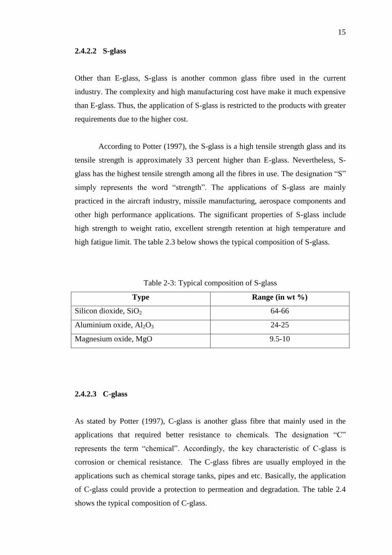
high fatigue limit. The table 2.3 below shows the typical composition of S-glass.
Table 2-3: Typical composition of S-glass
Type Range (in wt %)
Silicon dioxide, SiO2 64-66
Aluminium oxide, Al2O3 24-25
Magnesium oxide, MgO 9.5-10
2.4.2.3 C-glass
As stated by Potter (1997), C-glass is another glass fibre that mainly used in the
applications that required better resistance to chemicals. The designation “C”
represents the term “chemical”. Accordingly, the key characteristic of C-glass is
corrosion or chemical resistance. The C-glass fibres are usually employed in the
applications such as chemical storage tanks, pipes and etc. Basically, the application
of C-glass could provide a protection to permeation and degradation. The table 2.4
shows the typical composition of C-glass.

16
16
Table 2-4: Typical composition of C-glass
Type Range (in wt %)
Silicon dioxide, SiO2 64-68
Aluminium oxide, Al2O3 3-5
Calcium oxide, CaO 11-15
Magnesium oxide, MgO 2-4
Boron oxide, B2O3 4-6
Sodium oxide, Na2O 7-10
Potassium oxide, K2O 7-10
2.4.3 Forms of Fibreglass
Fibreglass is produced in a variety of forms. These forms include the roving,
chopped strands, mats and woven. Strand is most the basic form of continuous
fibreglass and it is formed through a group of parallel filaments.
Roving is the most common form of fibreglass. According to Mallick (2008),
roving is simply a group of parallel strands which gathered and wound on a
cylindrical tube. Generally, roving is used in continuous moulding operations such as
filament winding and pultrusion. The figure 2.7 below shows an example of
continuous strand roving.
Figure 2-7: An example of continuous strand roving (GP Impex, 2010)

17
17
Based on van der Woude and Lawton (2010), the continuous strands can be
cut into shorter lengths to produce another form which is chopped strands. The
chopped lengths are usually in the range of 3 mm to 50 mm. The chopped strands are
usually used to reinforce the thermosetting and thermoplastic resins. Besides, the
chopped strands are often applied in the injection moulding. The figure 2.8 below
shows an example of chopped strand.
Figure 2-8: An example of chopped strands (LBIE, 2009)
Chopped strands mat (CSM) is another popular form of fibreglass. CSM is
produced by spreading the longer chopped strands evenly in a random pattern and
mixing the chopped strands with the resinous binders. The CSM is usually used in
hand lay-up moulding, press moulding, autoclave moulding and various continuous
impregnating processes. Besides, CSM provides isotropic properties which mean the
product has the equal properties in all directions. The figure 2.9 below shows an
example of chopped strands mat.
Figure 2-9: An example of chopped strands mat (QDC, S.L., 2010)

18
18
Other than the forms mentioned above, fibreglass can be found in the woven
form as well. Woven roving is another common type of fibreglass used in the current
industry. According to Lubin (1975), it is produced by weaving the continuous
strands in two mutually perpendicular directions and the properties of the woven
roving are largely depend on the style of weaving. Woven roving is often used as
reinforcement of thermosetting polymers in a variety of applications. The figure 2.10
below shows an example of woven roving.
Figure 2-10: An example of woven roving (DIYTrade, 2007)
2.5 Polymer Matrix
Generally, fibreglass composite materials consist of fibreglasses bonded to a matrix
with different interfaces between them. In another word, matrix acts as an
intermediate between the fibreglass to adhere and keep the fibreglass in a fix location
and orientation. Most of the fibreglass composite materials in the industry are in the
form of laminate which means that the materials are made by depositing several
layers of fibreglass and matrix and consolidating them to a certain thickness.
According to Tucker and Lindsey (2002), besides keeping the fibreglass in
place, matrix is used as a medium to transfer the stresses or loads between the
fibreglass as well. Nevertheless, matrix provides protection for the fibreglass from
the environmental damage and the surface degradation caused by the abrasion. Thus,
the configuration of the fibreglass and matrix is always a crucial step in fabricating a
fibreglass composite material.

19
19
There are various matrix materials which include the polymer matrix, ceramic
matrix and metallic matrix. Among these materials, the polymer matrix is the most
common used matrix in the industry. While the ceramic and metallic matrixes are
used mainly for high temperature applications.
As stated in Callister (2006), a polymeric material is formed by a group of
polymer molecules with similar chemical structure and connected together by strong
covalent bonds. For the applications of polymer matrix, the thermoset polymers and
thermoplastic polymers are the most widely used matrix materials largely due to its
simplicity of processing.
According to Biron (2007), in a thermoset matrix, the molecules are
chemically bonded together by cross-links and form a three-dimensional network
through the covalent bonding. Often, the term, resin, is applied in the industry to
describe the resulting polymer. The thermoset polymer could not be melted by the
heat once the cross-links are formed. However, if the number of cross-links between
the molecules is less, the polymer could still be softened at elevated temperature.
There are few types of resins which are commonly being used such as the polyester,
epoxy, vinyl ester and etc.
While for the thermoplastic matrix, as claimed by Tucker and Lindsey (2002),
there are no chemical linkages between the individual molecules. The molecules are
not chemically bonded, but held by weak bonds or intermolecular forces such as the
van der Waals bonds and hydrogen bonds. Thus, the thermoplastic polymer could be
melted and softened by the heat and reshaped accordingly as desired. The examples
of thermoplastic matrix resins include the polyamide, polysulfone, polyphenylene
sulfide, polyether ether ketone and etc.
As mentioned above, there are plenty of polymer matrixes available in the
industry. However, due to the market constraints, the thermoset matrixes are applied
at most of the time. Nevertheless, the thermoplastic matrixes are seldom applied in
the application of go-kart too. Thus, the reviews will be focused more on the
thermoset matrix. For further information on thermoplastic matrix, refer to the
Appendix D as attached.

20
20
2.5.1 Polyester Resin
As stated by Mallick (2008), polyester resin is an unsaturated resin formed by the
reaction of dibasic acids with polyhydric alcohols. The polymeric resin is obtained
by dissolving the mixture in a reactive monomer such as styrene. By dissolving in
styrene, the viscosity would be reduced and make the resin easier to handle. The
solution could be cured or polymerized through the heating process to provide a
strong cross-linked structure. The curing process is often carried out with the use of
catalyst or accelerator. The properties of polyester resin are often depends on the
density of the cross-links.
The polyester resin is the most popular resin used in fibreglass products. The
combination of polyester resins and fibreglass composite materials offer a wide range
of properties to a certain product. Polyester resin is much cheaper as compared to the
other resins. Besides, the ease of handling the resin is another attractive point of
using polyester resin. The hand lay-up method is usually employed with the
application of polyester resin.
Other than that, the polyester resin has a good resistance to corrosion and
degradation caused by the chemical attacks. Excellent electrical properties could be
provided by the polyester resin as well. Nevertheless, other composite properties
such as lower viscosity and fast curing time are the advantages of using polyester
resin.
According to van der Woude and Lawton (2010), the principal disadvantage
of polyester resin over the other resins is the high volumetric shrinkage. The
shrinkage would results in uneven depression on the surfaces and affects the
appearance of the product. This issue is strictly not allowed in the applications where
Class A surface quality is important such as automotive industry. However, some
finishing process can be carried out to minimize the poor surface finish.

21
21
2.5.2 Epoxy Resin
According to Shenoi and Wellicome (1993), epoxy resin is formed by the reaction of
three members’ rings which is known as epoxy. An epoxy resin could contain few
epoxy groups. The epoxy groups are referred to the chemical groups containing of an
oxygen atom bonded with two carbon atoms, which is the three members ring.
Similar to the polyester resin, curing is needed to produce an insoluble cross-linked
structure. However, instead of catalyst, the curing agent used by epoxy resin is
hardener. Often, amines are used to cure the epoxy resin where both the epoxy and
amide take place in a chemical reaction to create the molecular structure.
Epoxy resin has the excellent mechanical properties and good resistance to
the chemicals which are much better than the polyester resin. Due to these
advantages, it is the most common used resin in the high performance industry such
as aircraft manufacturing. Besides, epoxy resin offers a wide variety of properties
through the selection of curing agents, hardening method and modification.
Nevertheless, the epoxy resin has the first rate adhesion ability and the strong
adhesion is available to a variety of materials. The low shrinkage during the curing
process is further enhanced the adhesion as a rigid and unstrained adhesive bond
could be formed. Other than that, the attributes such as good electrical properties,
better water resistance and thermal stability are the attractive points of epoxy resin.
On the contrary, the higher cost than polyester resin and longer curing time
are the main disadvantages of the epoxy resin. Often, an epoxy resin takes few days
to be cured instead of few hours of curing in polyester resin. Thus, the applications of
epoxy resin are limited to the products where the requirements are high. Besides, the
possible hazards in handling the resins and hardener are another obstruction in
applying the epoxy resin.

22
22
2.5.3 Vinyl Ester Resin
As similar to polyester resin, vinyl ester resin is an unsaturated resin formed by
dissolving in the styrene monomer which can reduce the viscosity of the mixture. As
stated by Shenoi and Wellicome (1993), the vinyl ester resin will reacts with the
styrene to form the rigid cross-links between the molecules. The curing process is
similar to the polyester resin as well. A unique point of vinyl ester resin that
differentiates it from the other resins is that it contains a number of hydroxyl groups
which will form the hydrogen bonds with the similar groups on a fibreglass surface.
This would results in better wet-out and creates a good adhesion with the fibreglass.
While for the properties of the vinyl ester resin, it is analogous to the
polyester resin in certain points too. The curing time is fast and the viscosity is lower
due to the styrene monomer. Besides, vinyl ester resin has an excellent chemical
resistance and tensile strength which are on par with the epoxy resin. On the other
hand, the cost for a vinyl ester resin is higher than polyester resin but lower than
epoxy resin. Nevertheless, vinyl ester resin provides a moderate adhesion power
which is slightly higher than the polyester resin. As similar to the polyester resin, the
high volumetric shrinkage happened in vinyl ester resin as well.
2.6 Fabrication Process by Using Fibreglass Materials
The fabrication process of fibreglass composite materials is rather simple and
inexpensive among the available materials in the market. The materials needed for
the fabrication of a fibreglass product could be as simple as the moulds, resins,
fibreglass and finishing materials.
Moulding is always the first step to start the fabrication process. The moulds
could be made by a variety of materials such as plywood, cardboard, Styrofoam,
aluminium sheets and etc depend on the requirements or specifications of a particular
product. Often, the surface of the mould is applied with a layer of release agents such
as wax, oil or release coating like poly vinyl acetate (PVA) to ensure the mould can

23
23
be released or unplugged smoothly in the end of the process. Nevertheless, a gel coat
is always sprayed on the surface of the mould after the layering of release agents. A
gel coat is a resin-based surface coating which can provide a better surface properties
and achieve a desired appearance as the gel coat is available in a wide range of
colours.
After the moulding process, the next step would be the layering of fibreglass
and resins. As mentioned earlier, fibreglass is available in different forms such as
roving, mats, chopped strands and etc. The selection of forms is always depends on
the applications and the fabrication process. Normally, the catalyzed resin mixtures
are applied on the mould followed by the layering of fibreglass. This step is repeated
until the required coverage and thickness are achieved. The resins have to be mixed
with the catalyst or hardener to start with the hardening process. Catalyst is a
corrosive material, thus, the mixing ratio must be in accordance to the specified
requirement and extra care is needed during the process.
In some of the applications where the surface properties are important, the gel
coat would be applied again to enhance the smoothness of the surface. Once all the
processes have been done, the product would be allowed to settle down for a period
of time before removing the mould from the final product. Sanding or grinding could
be carried out to eliminate the rough spots on the surface to have a better surface
finishing.
2.6.1 Hand Lay-Up Method
Hand lay-up method is the first and most widely used technique for producing the
fibreglass composite materials. The moulds can be made from various materials such
as wood, steel, plaster and etc. Often, a gel coat is applied on the surface of the
mould to obtain a better finishing and enhanced resistance to chemical attacks. The
catalyzed resin mixtures are then brushed manually on the mould followed by the
layering of fibreglass. Polyester and epoxy resins are the common resin used with

24
24
this technique. Besides, hand lay-up method is always a good choice for small scale
production as the cost is much lower and the fabrication process is simpler.
2.6.2 Spray Deposition Method
Spray deposition is a technique where the chopped fibreglass and resins are sprayed
simultaneously onto the surface of the mould using the sprays. In another words, it is
a mechanized version of hand lay-up method. Thus, the production rate is much
higher than the manually controlled hand lay-up method. Nevertheless, the gel coat is
applied on the surface of the mould to get the same effects as in hand lay-up method.
.
2.6.3 Filament Winding Method
In the filament winding method, the fibreglass rovings are winded continuously over
a rotating mandrel. The winding could consist of few layers of fibreglass in the same
or different orientation. The fibreglass could be impregnated with the resins prior to
winding. The common resins used are polyester resin and epoxy resin. The process is
considered done after the curing is carried out and the mandrel is removed.
2.6.4 Injection Moulding Method
Injection moulding is a common technique used for producing fibreglass composite
materials. The molten polymer matrixes which are often the thermoplastic polymers
are mixed with the fibreglass in the mixing chamber and being forced into a mould
cavity under the high pressure. The cost of the injection moulding method is much
higher than the other techniques largely due to the complexity of the mould.

25
25
2.6.5 Pultrusion Method
Pultrusion is a continuous manufacturing process where the fibreglass in the form of
mats or rovings is impregnated continuously in a resins bath and pulled through a
heated die where the resins undergo the polymerization process. The pultrusion
method could only produce the products with uniform cross sections such as rods,
hollow tubes and squares. The pultruded fibreglass composite materials have the
characteristics of high strength to weight ratio, excellent dimensional stability, good
structural properties and etc.
2.7 Selection of the Types of Fibreglass and Resin
Since the fibreglass composite material is chosen as the main material of this project,
the selection of material would be emphasised on the fibreglass material itself rather
than the other materials in the market. The selection of fibreglass materials would be
performed on the types of fibreglass used, the forms of the fibreglass materials, the
types of resins used, moulding materials and the processing methods.
Based on the reviews done, there are a range of materials available in the
industry. However, in this country, the resources available are limited. For instant,
the obtainable type of fibreglass in the market is mainly the E-glass fibreglass and
the resins offered would be the polyester and epoxy resin. Nonetheless, the chopped
strands mat (CSM) is the most common form of fibreglass available. Besides, the
choice of processing methods is limited as well. For a small scale production, the use
of epoxy resin is not practical as the cost implied is much higher and the hand lay-up
technique is the most commonly used method.
As in this project, the aims are focused on the low cost and local sourced
materials. Thus, the selection would largely depend on the availability of the
materials in the market. Importing a material is impractical as it goes against with the
objectives of the project.

26
26
2.8 Concept of Design
In this project, the design of the kart chassis is mainly based on the concept of
monocoque design that applied in the racing cars or even some of the high end road
cars. Basically, a monocoque design is the concept where the entire chassis is built in
a single unit. A remarkable example would be the McLaren’s MP4-12C. The chassis
of the car was built in a one piece carbon-fibre tub. The figure 4-1 below shows the
carbon-fibre monocoque design of the MP4-12C.
Figure 2-11: The carbon-fibre monocoque chassis of MP4-12C (McLaren
Automotive, 2011)
As mentioned above, the MP4-12C’s chassis was a carbon-fibre monocoque
chassis. The properties of carbon-fibre are definitely more superior compared to the
fibreglass. So, the questions arose when the design is to be done in the fibreglass
material. The Lotus Elite built in 1957 would undoubtedly be the answer for this.
The chassis of the car was entirely made of fibreglass. In another way of speaking,
the car was structured on a fibreglass monocoque chassis. Since the fibreglass is
chosen as the building material for the go-kart in this project, it is feasible to design
as what have been done in the Lotus Elite.

27
27
Nevertheless, the design of the go-kart chassis in this project is largely
inspired by the Formula 1’s car body. The figure 4-2 below shows an example of the
Formula 1’s car.
Figure 2-12: An overhead view of the McLaren MP4-26 (McLaren F1, 2011)

28
28
2.9 Design Requirements
Maurizio, Giuseppe, and Gianpiero (2004) did a research in the vertical deflection of
a go-kart chassis when it was loaded with the load until 30 kg. The displacement in
the vertical direction was obtained as below.
Table 2-5: The displacement obtained under a given load
Load (kg) Displacement (mm)
0 0
5 0.36
10 0.72
15 1.10
20 1.49
25 1.86
30 2.24
The relationship between the load and the displacement is shown in the figure
2-13 below.
Figure 2-13: The relationship between displacement and given load

29
29
If a load with 70 kg (approximately a human weight) is loaded on the chassis,
by using the equation obtained from the graph, the displacement achieved is 5.229
mm. Thus, it can be concluded that, for a go-kart chassis loaded with 70 kg of weight,
the bending deflection of the chassis obtained is 5.229 mm. The research finding
shown was carried out on a conventional tubular go-kart chassis. As in this project,
the design of the chassis is different from the conventional chassis. Thus, the value
needs not to be the exact displacement for a load of 70 kg but it acts as a reference
point for displacement obtained.
Meanwhile, for the torsional stiffness of a go-kart, in Liang, Yu and Wu
(2007), it is stated that a recommended torsional stiffness for a go-kart should be at
least 165 Nm/deg. However, there is an unanswerable doubt in this value whereby
the amount of force and moment exerted at the kart body to obtain the value is not
known. Thus, if this value is to be the reference value for the project, certainly there
would be some questions arise. Somehow, the figure 2-14 shows the force-deflection
curve for a car chassis testing.
Figure 2-14: The force-deflection curve for a chassis testing (Rileydynamics, 2011)

30
CHAPTER 3
3 METHODOLOGY
3.1 Process Flow of the Project
Methodology could be explained as a description of the proceeding of a project. In
another words, it is a set of methods or procedures of a project. Often, a flow chart is
used as a tool to represent the procedures which show the steps from the start to the
end of a project. A flow chart of this project is attached at the following page

31
31
Figure 3-1: Flow chart of the project
End
Start
Literature Review
Conceptual Design
Embodiment Design
CAD Modeling
Finite Element
Analysis
Prototyping
32
32
3.2 Literature Review
Literature review is the process of obtaining and summarizing the related information
through the reviews on the journals, books, internet resources, articles and etc. It
provides the background knowledge of the studies and worked as a guide to the later
part of a project. Similarly, in this project, the information of a go kart such as the
history and the components are studied in the earlier part of this stage. Nevertheless,
the research on the material is carried out as well. The information like the
applications of fibreglass materials, the properties of fibreglass, the characteristics of
different polymer matrixes and the fabrication process of fibreglass materials are
obtained and studied through the literature review. An evaluation of materials is
performed in this stage of process as well.
3.3 Conceptual Design
Conceptual design is the process where the conceptualization is performed. It is a
stage where the ideas of the design are demonstrated through the drawings or
sketching. The concepts of the design are generated based on the information
obtained and brainstorming is always a good method to create an idea. Nevertheless,
the conceptual design often involves the activities like description of overall concept
and definition of the specifications. As in this project, the concept of how the
fibreglass composite materials are applied to the structure of a go kart is determined
in this stage.

33
33
3.4 Embodiment Design
Embodiment design is carried out after the concepts of the design are generated. In
this process, the preliminary design layouts and configurations are developed from
the selected concept. The technical criteria are identified in the embodiment design
as well. In this stage of the project, the architecture, shape and general dimensions of
the go kart are established.
Nevertheless, the materials are selected before proceed to the modelling of
the design. As the fibreglass composite material is chosen as the principal material of
this project, the material selection process will be focused on the selection of
fibreglass rather than the other available materials in the market. The decision
matrices such as Pugh selection method is used as a tool in the material selection
process.
3.5 CAD Modelling
CAD modelling is a process to create computerized models for a product before it is
physically produced. This process enables the visualization of a design and
identification of potential design problems before the prototyping process. As in this
project, the detail drawings and the final design specifications of the go kart are
worked out. Then, the go kart with predetermined dimensions and patterns is drawn
and modelled by the modelling software and a finite element analysis will be carried
out on the completed model to determine the performance of the design.

34
34
3.6 Finite Element Analysis
Finite Element Analysis or FEA is a tool used to identify the performance of a model
by stressing the model to obtain the specified results. The detailed visualization of
where the parts would bend or twist and the distribution of stresses would be
indicated through the simulation. Modifications could be done to improve the areas
where the stress sustainability is weak. Finally, a final design review is performed to
ensure the design is workable and ready for prototyping.
3.7 Prototyping
A prototype of the finalized design is built and the performance of the design is
verified to comply with the design requirements.

35
35
CHAPTER 4
4 RESULTS AND DISCUSSIONS
4.1 Design of Go-kart
4.1.1 First Kart Chassis Design
As mentioned in the earlier section, the design of the chassis is inspired from the car
body of a Formula 1’s car. The concept of having a cockpit is implemented.
Nonetheless, in the Formula 1’s car, the car body can be considered as a full covered
body with an opening for the driver to enter into the driving cockpit. However, in our
go-kart design, the chassis is built in an open chassis style while maintaining the
driving cockpit design. The opening area of the chassis is designed with the purpose
to ease the installation of the engine and any other relevant mechanisms. Nonetheless,
the ease of maintenance is another consideration for an open chassis. The figure 4-1
and figure 4-2 shows the first design of the go-kart chassis in this project.

36
36
Figure 4-1: The first design of the go-kart chassis
Figure 4-2: The wireframe model of the first go-kart chassis design

37
37
As shown in the figure 4-1, the seat is designed in a single unit together with
the chassis. Nevertheless, there are some holes available at the both side of the kart
body to allow the air flow into the engine compartment for cooling effect. Besides,
the air resistance can be reduced as well.
Basically, after the consideration of the difficulties that would be faced
during the fabrication process, the design is simplified. Instead of having a base that
is in a curvature form, the base is modified to become a flat base design.
Nevertheless, the design of the seat is simplified as well since the seat is not the
focus in the project. The figure 4-3 and figure 4-4 shows the modified version for the
first chassis design.
Figure 4-3: Modified version of first kart chassis design

38
38
Figure 4-4: The wireframe model of the modified first go-kart chassis design
Table 4-1: Summary of the first design
Pros Cons
Open chassis
Ease of installation
Ease of maintenance
Opening of holes to reduce air
resistance and help in ventilation
Extra part such as seat
Unnecessary curvature design
Potentially limited space in the
driving cockpit

39
39
4.1.2 Second Kart Chassis Design
For the second design of the go-kart chassis, it is actually modelled based on the first
design. The variations include the removal of the seat from the chassis design. As
mentioned above, since the seat is not the focus, it would be reasonable to be
removed from the design. Besides, the front cover on the top of the chassis is
trimmed to a smaller size with the purpose to allow more rooms or space for the
installation of steering system. Nonetheless, a smaller cover could provide a more
comfortable driving condition. Moreover, the thickness of the chassis is set to be 3.5
mm. The figure 4-5 below shows the design of the modified go-kart.
Figure 4-5: The second design of the kart chassis
Simulation on the displacement has been carried out in this design as well.
The load assumed is 70 kg or approximately 687 N, which is similar to a human
weight and it is applied on the sitting area of the chassis. The maximum displacement
of the go-kart chassis could be obtained. The figure 4-6 below shows the simulation
of displacement for this design.

40
40
Figure 4-6: The simulation result for second design of kart chassis
The data obtained from the simulation showed that the maximum
displacement achieved is 22.99 mm. The weakest area of the chassis is believed to be
the sitting area. Obviously, the displacement of 22.99 mm is not a satisfied result as
it is largely against the desired value of displacement. Modifications and
improvements need to be done in order to achieve a better result.
Table 4-2: Summary of the second design
Pros Cons
Removal of seat
Smaller front cover
Ease of installation
More space in the driving cockpit
Large displacement

41
41
Thus, another variation based on the same design of chassis has been made to
find out a feasible solution. Since the application of fibreglass allows the thickness of
the chassis to be varied by adding or reducing the layers applied, the thickness of the
chassis is decided to be increased to 15 mm which is considerably large to find out
the effects on the displacement result. The figure 4-7 shows the simulation results for
the chassis of improved thickness.
Figure 4-7: The kart chassis with 15 mm thickness
Dramatically, by applying the same amount of load, the maximum
displacement obtained is about 0.2786 mm. The value obtained is much lower as
compared to the previous simulation. Thus, it can be conclude that a chassis with
thicker wall especially at the area where the load taking is largest could provide a
better displacement result and thus higher stiffness. However, thicker wall would
contribute to the increment of chassis mass as compared to the others and the issue of
over designed would arise.
42
42
Table 4-3: Summary of the improved second design
Pros Cons
Small displacement
Higher stiffness
Thicker wall
Heavy chassis
Over designed
4.1.3 Third Kart Chassis Design
From the simulation of thicker chassis wall, it is very obvious that the design of 15
mm is unnecessary. Thus, for the third design of the go-kart chassis, the thickness of
wall is maintained at 3.5 mm. Nonetheless, since the second design with a 3.5 mm
wall thickness does not give a convincing displacement result, a series of
reinforcement methods is tried and tested in the third design of kart chassis with the
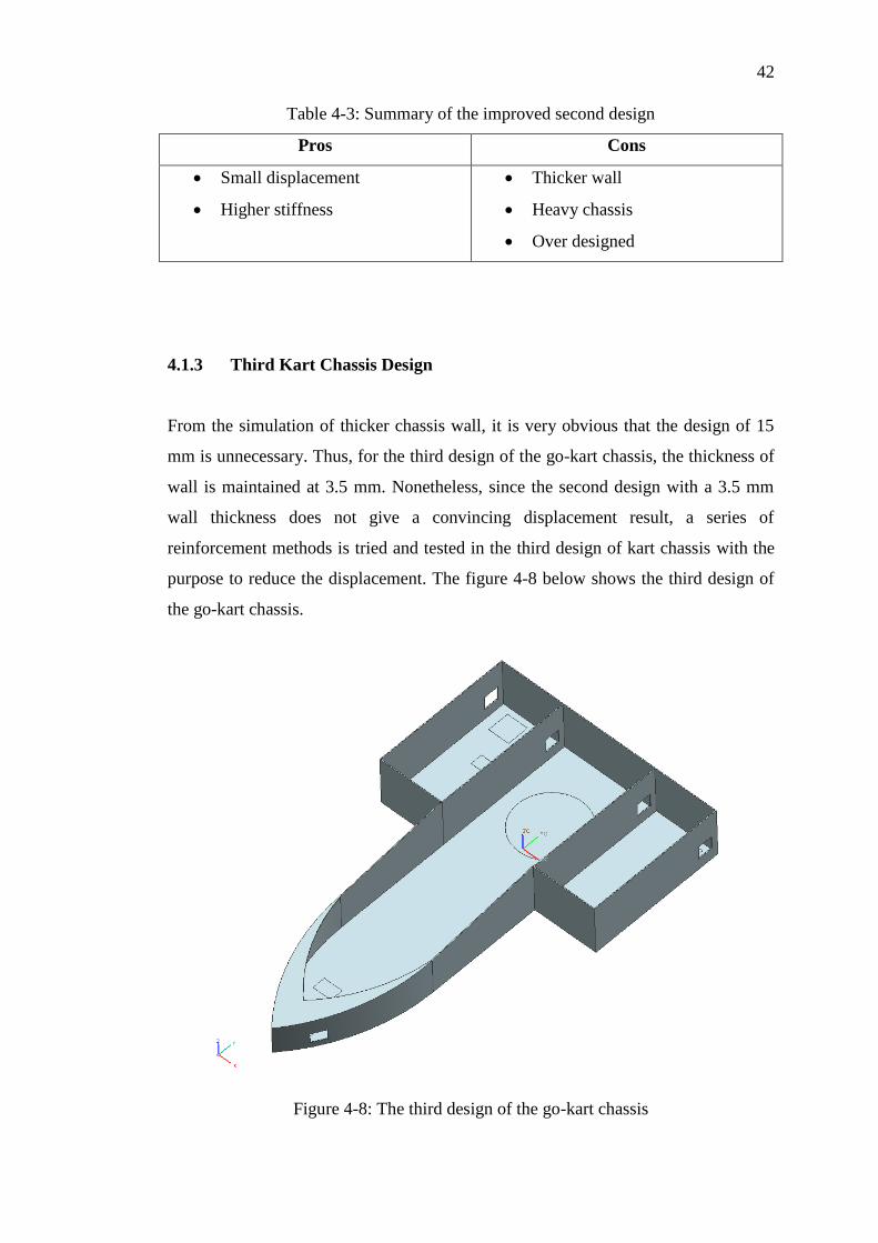
purpose to reduce the displacement. The figure 4-8 below shows the third design of
the go-kart chassis.
Figure 4-8: The third design of the go-kart chassis

43
43
Basically, as shown in the figure 4-8, some modifications have been done on
the third kart chassis based on the model of second kart design. Thoroughly, the
length of the driving cockpit is extended to provide a larger legroom to the driver and
thus, a more comfortable driving condition. Besides, the front cover is further
trimmed to a smaller size to ease the installation of driving mechanism such as petal,
brake and etc.
Under the consideration of ease of fabrication, some curvature parts of the
chassis are changed to a simple and squarish design. Nonetheless, the holes available
at the both side of the kart body are removed as well. However, it is known that a
sharp corner would give an increase in the stress concentration and this high stress
concentration would lead to a design failure. Thus, the effect of these eliminations
would be examined in the simulation of the design.
Table 4-4: Summary of the third kart chassis design
Pros Cons
Extension of driving cockpit
More legroom
Ease of installation
Ease of fabrication
Simplicity of design
Smaller displacement as
compared to previous design
Higher stress concentration at
sharp corner

44
44
4.1.3.1 First Version of Third Kart Chassis Design
Figure 4-9: The first version of third kart chassis design
Figure 4-10: The wireframe model for the first version of third kart chassis design

45
45
Figure 4-11: The simulation result for the first version of third kart chassis design
As shown in the figure 4-9, some fibreglass stripes have been added to the centre
bottom of the chassis where the load taking is considerably the largest. This is done
to strengthen the chassis by the mean of adding the thickness.
From the simulation results shown in the figure 4-11, the displacement
obtained is 16.55 mm. The value is lowered as compared to the second chassis
design but still higher than the desired displacement. Thus, it can be said that the
addition of stripes help in the reduction of displacement and further reinforcements
have to be done to improve the value. Besides, the effect of eliminations of the
curvature design and removal of holes do not give a negative result in the simulation
as shown. Hence, for the sake of fabrication, the eliminations are considered
workable even though it might not be the same story in the practical.

46
46
4.1.3.2 Second Version of Third Kart Chassis Design
Figure 4-12: The second version of third kart chassis design
Figure 4-13: The wireframe model for the second version of third kart chassis design

47
47
Figure 4-14: The simulation result for the second version of third kart chassis design
As shown in the figure 4-12, the length of the fibreglass stripes has been increase to
the side wall of the chassis. From the simulation results shown in the figure 4-14, the
displacement obtained is 14.70 mm. The value is lowered as compared to the first
version of the design but still higher than the desired displacement. Thus, further
reinforcements have to be done to improve the value.

48
48
4.1.3.3 Third Version of Third Kart Chassis Design
Figure 4-15: The third version of third kart chassis design
Figure 4-16: The wireframe model for the third version of third kart chassis design

49
49
Figure 4-17: The simulation result for the third version of third kart chassis design
As shown in the figure 4-15, instead of increasing the length of the fibreglass stripes
as what have been done in the second version, the stripes are added at the inner wall
of the cockpit. Nonetheless, additional reinforcement stripes are added at the rear
wall of the chassis as well. From the simulation results shown in the figure 4-17, the
displacement obtained is reduced dramatically from the 14.70 mm in the second
version of design to 6.344 mm. The value is much lowered as compared to the
previous versions of the design and somehow it can be considered near to the desired
value of 5.229 mm.
50
50
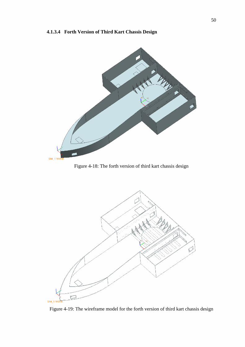
4.1.3.4 Forth Version of Third Kart Chassis Design
Figure 4-18: The forth version of third kart chassis design
Figure 4-19: The wireframe model for the forth version of third kart chassis design

51
51
Figure 4-20: The simulation result for the forth version of third kart chassis design
As shown in the figure 4-18, a new type of reinforcement is introduced. The
triangular type of reinforcements is implemented at the inner wall of the cockpit and
two stripes are added at the outer wall of the driving cockpit. From the simulation
results shown in the figure 4-20, the displacement obtained is 7.293 mm. The value
obtained is lowered as compared to the previous version of the design except the
third version. Regardless of this, the displacement obtained is still higher than the
desired displacement. It is worth to mention that the structure of the triangular type
of reinforcement might cause a potential issue to the placement of the other
components in a kart such as the rear driving axle. Thus, further reinforcements have
to be done to improve the design.

52
52
4.1.3.5 Fifth Version of Third Kart Chassis Design
Figure 4-21: The fifth version of third kart chassis design
Figure 4-22: The wireframe model for the fifth version of third kart chassis design

53
53
Figure 4-23: The simulation result for the fifth version of third kart chassis design
As shown in the figure 4-21, the stripes are added at the inner wall of the cockpit
only. This version of design is actually a simplified design from the other versions.
Besides, the front cover is removed to test the effect on the displacement value. From
the simulation results shown in the figure 4-23, the displacement obtained is 6.817
mm. The value is lowered as compared to the previous versions of the design except
the third version. However, the ease of fabrication on the reinforcement is the
highlight point of this design. Nonetheless, a simulation has been carried out on this
version of design to test its torsional stiffness and deflection when it is under loading.
Table 4-5: Table of force, displacement and torsional stiffness
Force (N) Displacement (mm) Torsional Stiffness (Nm/deg)
150 34.29 12.25
300 68.57 12.34
450 102.9 12.48
600 137.1 12.69
750 171.4 12.97

54
54
Figure 4-24: The graph of torsional stiffness against force
Figure 4-25: The graph of displacement against force
From the figures above, it is obvious that the torsional stiffness and the
deflection on the chassis are increase when a greater force are exert. This matched
the trend as shown in figure 2-14. For the torsional stiffness of the chassis, it shows
an increasing trend. As stated by Liang, Yu and Wu (2007), in a real kart, the
torsional stiffness of a go-kart can be controlled through the positioning of extra
members and the adjusting of the width in between the two kingpins. Nevertheless, a
torsional bar is always added to alter the torsional stiffness of a kart. Thus, it is
believed that the torsional stiffness of kart, when comes to a point, can be altered
accordingly to suit with the different driving condition.

55
55
4.1.3.6 Summary of Third Kart Chassis Design
Basically, there are five different versions in the third design of the go-kart chassis.
Each of them is different in the mean of reinforcement used. The table 4-6 below
shows the displacement result obtained for each version of design.
Table 4-6: Summary of the displacement obtained for each version of design
Design Displacement (mm)
Version 1 16.55
Version 2 14.70
Version 3 6.344
Version 4 7.293
Version 5 6.817
Obviously, the third version of design has the lowest displacement when it is
loaded with a load of 70 kg. The next would be the fifth version. As the ease of
fabrication is one of the consideration when comes to a design, the fifth version of
design would be the choice. Thoroughly, the reinforcement used in the fifth version
can be considered as a simpler design yet do not sacrifice the bending rigidity of the
chassis. The displacement obtained is slightly higher than the second version of
design and of course the desired displacement of 5.229 mm. However, as for the go-
kart, the chassis is actually acts as a suspension as well. Given a same loading, the
lower bending deflection does not always represent a good design. A lower bending
deflection could give a higher stiffness of the body. In the case of go-kart, high
stiffness would result in a bumpy ride when it comes to an uneven road.
Thus, the fifth version of the third kart chassis design is chosen as the design
to build out the prototype model. Refer to appendix E for the dimension of the design.

56
56
4.2 Fabrication of Go-kart Chassis
4.2.1 Fabrication Process of Go-kart Chassis
Prior to the discussion, it is worth to inform that the type of fibreglass used in this
project is the E-glass chopped strands mat and the resin used is the polyester resin.
The moulding materials used in this project is plywood and polystyrene foam. The
polystyrene foam is used to form the curvature of the kart. The figure 4-26 and figure
4-27 below shows the moulding for the go-kart chassis prototype.
Figure 4-26: The plywood moulding of the go-kart
Figure 4-27: The polystyrene foam moulding that form the curvature part of the kart

57
57
Subsequently, a layer of release agents is supposed to be applied onto the
surface of the mould to ease the removal process upon the completion. However, the
adhesive tape which has a much lower cost is used to replace the release agent. The
figure 4-28 below shows the complete mould for the outer part of the kart chassis
before proceed to the layering of fibreglass.
Figure 4-28: Completed mould
The hand lay-up method is used in this project and the fibreglass together
with the polyester resin was applied layer by layer until the targeted number of layers
was achieved. The prototype was allowed to be cured before the removal of mould.
Figure 4-29: Layering of fibreglass

58
58
After the removal of the mould, the inner part of the chassis is fabricated. The
processes mentioned above were repeated. The figure 4-30 shows the moulding of
the inner part.
Figure 4-30: Moulding of the inner wall
Upon the completion of the basic structure, the reinforcement strips as shown
in the figure 4-31 were layered to the centre area of the kart where the force is
considered to be the largest as mentioned in the section 4.1.3 above.
Figure 4-31: The reinforcement stripes on the chassis of the go-kart

59
59
4.2.2 Highlighted Issues during the Fabrication Process
Throughout the fabrication process, some problems have been encountered. First
would be the using of polystyrene foam as the moulding material. As the setting resin
generates heat, the polystyrene foam would be damaged, hence, produced a poor
surface finish. This is shown in the figure 4-32 in the Besides, even though a proper
mixing ratio of resin to hardener has been set, the gel time are still not stable due to
the surrounding temperature of the workplace. For example, in hot weather day, the
resin could become very sticky after the hardener has been mixed into.
Figure 4-32: The damage caused on the polystyrene foam
Nevertheless, it is found out that the fibreglass mat used did not have the
same thickness. This is shown in the figure 4-33 in the following page. Some areas of
the fibreglass mat are thinner and contain lesser amount of chopped fibre strands.
This could affect the strength of the structure if the area is considerably large.

60
60
Figure 4-33: Inconsistency in the thickness of the fibreglass mat
Besides, due to the hand lay-up method, air bubbles are formed easily when
the layered fibreglass is brushed with the resin. The air bubbles that trapped inside
tend to cause the porosity of the structure and hence, affect the strength of the
structure. It is found out that the air bubbles are hard to be removed if the hand lay-
up method was to be used. Besides, the design of sharp edges is believed to be the
reason for this issue as well. The figure 4-34 shows the severity of the air bubbles.
Figure 4-34: The air bubbles trapped inside the body of the chassis

61
61
4.3 Comparison between Experimental and Simulation Data
An experiment has been carried out after the prototype of the go-kart chassis is built.
The objective of the experiment is to verify the accuracy of the displacement
obtained experimentally as compared to the simulation result. A set of dial gauges
has been used to obtain the displacement of the chassis. The figure 4-35 below shows
the configuration of the experiment.
Figure 4-35: The strain gauge used to obtain the displacement reading
The experiment is done on different points on the chassis and the percentage
of difference between the simulation data and experimental results is calculated. The
position of the points tested is measured during the experiment and subsequently the
points are plotted in the CAD drawing to ensure the position is exactly the same with
the experiment. The figure 4-36 in the following page shows the points tested during
the experiment.

62
62
Figure 4-36: Points taken during the experiment
The results obtained are as shown below;
Table 4-7: Percentage difference between experimental displacement and simulation
data
Displacement
(experimental),
mm
Displacement
(simulation),
mm
Difference,
mm
Percentage of
Difference, %
Point 1 5.93 1.657 4.273 257.88
Point 2 6.21 4.970 1.240 24.95
Point 3 5.49 4.142 1.348 32.54
Point 4 3.97 2.899 1.071 36.94
Point 5 4.44 3.313 1.127 34.02
Point 6 4.66 3.727 0.933 25.03
Remarks: The percentage difference is obtained by dividing the difference in
between the two results by the displacement as in simulation and multiplies by
100 %.

63
63
Figure 4-37: The graph of percentage difference for each of the points
As shown in the figure 4-37 above, the result for point 1 is obviously an
outlier as the value is differed much from the other points. If the point 1 is taken into
consideration, the average percentage difference obtained would be 68.56 % which is
considerably large. However, if the point 1 is excluded from the calculation, the
average percentage difference obtained is about 30.7 %.
The reasons for the outlier point could be the human mistake when the
reading of the gauge is taken. Moreover, the points 1, 3 and 5 are actually obtained
from a same dial gauge and it can be seen that two out of three points obtained have
a larger percentage difference as compared to the others. Thus, it is suspected that
there is a possibility of dial gauge error.

64
64
4.4 Cost of Fabrication
Since the objective of this project is to develop a low cost fibreglass go-kart, the cost
would definitely be a concern. The fibreglass composite material used is in the
lowest price range. An example could be the polyester resin. It costs about RM10 to
RM12 per kilogram which is considerably the lowest price as compared to the other
resins such as the epoxy resin which could costs about RM40 per kilogram.
It is found that the overall cost to fabricate a fibreglass go kart chassis in this
project is about RM500. The fabrication cost includes the cost of material and the
tools and equipments as well. As mentioned in the section earlier, the cost to buy a
kart in Malaysia could simply costs around ten thousands ringgit. Hence, it can be
seen that the fabrication cost of this project is relatively cheap even though the cost
involved is only for the chassis.

65
CHAPTER 5
5 CONCLUSION AND RECOMMENDATIONS
5.1 Conclusion
Basically, the objectives of the project are achieved. A go-kart chassis is built by
using the fibreglass composite material and this fibreglass made go-kart chassis has
been simulated and tested by experiment in term of its bending deflection and
torsional stiffness. The cost implied is adequately suits with the project’s objective as
the use of materials such as the polyester resin is at the lowest price range. Although
the design of the go-kart chassis done in this project could not be considered fully
utilized the properties or strength of the fibreglass composite material, it can be said
that the performance in the mean of bending displacement gives a positive
representation that the fibreglass composite material is suitable to be used as the
building material of a go-kart chassis.
As for the design that has been prototyped in this project, there are actually a
number of rooms for improvement that can be done. However, due to the timeframe
provided, the improvements done are actually limited. Thus, further study would be
required in order to maximize the design and the application of fibreglass materials.
Nonetheless, from all the designs and studies that have been done, it can be
concluded that a go-kart chassis need not to be in the conventional tubular form. One
of the significant advantages of the application of fibreglass composite materials is
the design flexibility. Thus, by continuingly carry out the testing and researching in
the design of the go-kart chassis, an innovative and creative chassis can be developed
while optimizing the performance of the go-kart at the same time.

66
66
5.2 Recommendations
From the very beginning of the process, the selection on the type of material used is
very crucial to the entire project. As in this project, since the fibreglass composite
material is chosen as the material used, the selection would be largely on the types of
fibreglass used. Instead of the chopped strands mat that has a random pattern, it is
recommended to use the unidirectional fibreglass such as the roving strands, woven
roving and etc. By doing this, the orientation of the fibreglass can be manipulated
with and thus, maximizing the properties of the fibreglass material. Nevertheless,
epoxy resin is definitely at a higher rank than the polyester resin and it is applied in
most of the automotive applications. If the cost is not the focus of a project, it is
recommended to apply the epoxy resin.
Besides, moulding is the vital part when comes to the application of
fibreglass composite materials. Thus, a more versatile moulding material should be
used in order to have a more sophisticated design. As in this project, the design that
involved curvature part is hard to be implemented as the fabrication of the part is
definitely more difficult and the radius of the curvature is hard to be controlled by
using the moulding material like plywood. Thus, by resolving the moulding issue, a
design with sharp edges could be reduced which could in turn decreased the stress
concentration of that area and reduced the possibility of air trapped.
Nevertheless, it is noticed that the hand lay-up method used in this project
could invoke the issue of inconsistency while layering the fibreglass and this could
lead to different thickness obtained in a body. Thus, it is recommended that a more
machine dependant method should be used to replace the hand lay-up method.
In this project, the chassis is designed in an open chassis style. Since the
application of full covered chassis is very common in the racing industry, it is
recommended that a go-kart design with a fully covered chassis can be carried out.
Besides, since a torsional stiffness for a go-kart is always not known or not revealed
by the manufacturer, an onsite testing should be carried out in order to help in the
verification of the design.

67
67
REFERENCES
Biron, M. (2007). Thermoplastics and thermoplastic composites. Oxford: Elsevier
Limited.
Callister, W.D. (2006). Materials science and engineering: an introduction (7th
ed.).
NJ: John Wiley & Sons, Inc.
Cardarelli, F. (2008). Composite materials. In Material handbooks (p.1019). London:
Springer.
Commission Internationale de Karting (CIK)-FIA. C.R.G Kalifornia’s go kart chassis
frame homologation. Retrieved August 8, 2010, from
www.kartcrg.com/ingl/homol_ingl/pdf_omol/telai%20crg/kalifornia.pdf.
DIYTrade. (2007). Fibreglass woven roving. Retrieved August 14, 2010, from
http://www.diytrade.com/china/4/products/3500288/fiberglass_woven_roving.htm
Go-Kart Guru. (2008). Steering systems. Retrieved August 9, 2010, from
http://www.gokartguru.com/go_kart_steering_systems.php.
GP Impex. Retrieved August 14, 2010, from http://www.gpimpex.com/products.html.
International Recreational Go-Kart Association (IRGA)a. (1991). The evolution of
the kart. Retrieved August 6, 2010, from http://www.irga.us/story.htm.
International Recreational Go-Kart Association (IRGA)b. (1991). The story behind
the sport of karting. Retrieved August 6, 2010, from http://www.irga.us/story.htm.
John, R.a (2000). The history of go-kart. Retrieved August 7, 2010, from
http://www.goingkarting.co.uk/history-of-go-karting.html.
John, R.b (2000). Chassis. Retrieved August 8, 2010, from
http://www.goingkarting.co.uk/Chassis.html.
John, R.c (2000). Go-Kart Transmissions. Retrieved August 8, 2010, from
http://www.goingkarting.co.uk/Transmission.html.

68
68
Larry, A. J. (2006). History of go-kart. Retrieved August 7, 2010, from
http://www.articlesbase.com/sports-and-fitness-articles/history-of-go-carts-
25636.html.
LBIE. (2009). Wet chopped strands. Retrieved August 14, 2010, from
http://www.lbie.com/cstwet.htm.
Liang, C.C., Yu, C.H. & Wu, C.C. (2007). A Study on Torsional Stiffness of the
Competition Go-kart Frame. Retrieved April 17, 2011, from
library.witpress.com/pages/PaperInfo.asp?PaperID=17416.
Lubin, G. (1975). Handbook of fiberglass and advanced plastics composites. NY:
Krieger Publishing Co.
Mallick, P.K. (2008). Fiber-reinforced composites: materials, manufacturing, and
design (3rd
ed.). Boca Raton, Florida: CRC Press.
Maurizio, M., Giuseppe, M., & Gianpiero, V. (2004). Methods for the Evaluation of
the Go-kart Vehicle Dynamics Performance by the Integration of CAD/CAE
Techniques. Retrieved April 16, 2011, from
www.ingegraf.es/XVIII/PDF/Comunicacion17219.pdf.
McLaren Automotive. (2011). McLaren MP4-12C. Retrieved March 26, 2011 from
www.mclarenautomotive.com.
McLaren F1. (2011). Vodafone McLaren Mercedes MP4-26. Retrieved March 26,
2011 from http://mclaren.com/mp4-26.
Net Composites. (2008). Glossary. Retrieved April 13, 2011, from
http://www.netcomposites.com/glossary.asp?letter=g.
Nice, K. (2000). How differential works. Retrieved August 8, 2010, from
http://auto.howstuffworks.com/differential.htm.
Noble. A. (1997). Stress Concentration. Retrieved April 15, 2011, from
http://www.sv.vt.edu/classes/MSE2094_NoteBook/97ClassProj/anal/noble/stress_
conc.html.
Partsquip. Retrieved August 9, 2010, from
http://www.partsquip.com/node/13445/87/8783.
Potter, K. (1997). An introduction to composite product: design, development and
manufacture. London: Chapman & Hall.

69
69
QDC, S.L.. E-glass chopped strand mat. Retrieved August 14, 2010, from
http://www.grupo-quimiasiatico.com/quimioasiatico/app/fibra-vidrio/fibra-
vidrio.asp?idioma=en&id_producto=1&id_categoria=.
Rileydynamics. Frame and Chassis Stiffness Testing. Retrieved April 17, 2011, from
http://rileydynamics.com/m-eng%20web/sec10.htm.
Sapiensman. Retrieved August 9, 2010, from
http://sapiensman.info/auto.php?psps_page=4.
Shenoi, R. A. & Wellicome, J. F. (Eds.). (1993). Composite material in maritime
structures. Cambridge: Cambridge University Press.
Tony Borroz. (2009). Corvette adds some fiber, flair to American Road. Retrieved
August 12, 2010, from http://www.wired.com/thisdayintech/tag/fiberglass/.
Tsavo Media Canada. (2008). Go karts components. Retrieved August 8, 2010, from
http://www.guide2gokarts.com/components/.
Tucker, N. & Lindsey, K. (Eds.). (2002). An introduction to automotive composites.
UK: Rapra Technology Limited.
Van der Woude, J.H.A. & Lawton, E.L. (2010). Composite design and engineering.
In Fiberglass and glass technology, part 1 (p.125). US: Springer.
Walker, M. (2005). Go-kart frames. Retrieved August 8, 2010, from
http://ezinearticles.com/?Go-Kart-Frames---Choosing-the-Right-One-for-
You&id=26713.

70
70
APPENDICES
APPENDIX A: History of Go-Kart
The first go-kart was invented by Art Ingels in 1956. The kart was simply built by
simple-structured frame, small engine and wheels. Thoroughly, the kart built by Art
Ingels was framed by rugged tubular chassis with the West Bend 2-stroke engine
mounted on a set of semi-pneumatic tyres. This combination was simple yet
sustainable to the body weight of Art Ingels which was around 100 kg. Accordingly,
this has provided a basis for the design of go-kart in the future invention.
The achievement of Art Ingels has drawn the attention on this miniature
racing vehicle from the people around him. In the year of 1958, an American
company, Go Kart Manufacturing Co. became the first go-kart manufacturer.
Nevertheless, the involvement of McCulloch in the go-kart engine business in 1959
has made the McCulloch became the first company to produce engines for karts. The
first engine created by McCulloch was the McCulloch MC-10. It was designed
through the modification of a chainsaw 2-stroke engine produced by McCulloch.
In the 1960s, the kart racing has spread widely in Europe countries. As a
result, more engine manufacturing companies were established in Europe rather than
in America. The most significant evolution at this period was the application of
motorcycle engine in go-kart. Furthermore, during the 1970s, the modern design of
go-kart came into force. The engines were placed at the side of the seat instead of the
position at the rear in the earlier design. Due to this change, the cooling of engines
was more effective as the increase of air flow to the engines. Besides, more legroom
was provided through this change.

71
71
APPENDIX B: Chassis
In the earlier design of go-kart chassis, the stiff chassis with shorter bars that crossed
over each other is always utilized by the manufacturers. This kind of chassis would
experience break down easily as the go-kart is more likely to turn stiffly at the
corners. As the time evolved, the longer bars are used for the chassis. This provides
more flexibility for the go kart to deal with different kind of track surfaces.
According to Tsavo Media Canada (2008), the chassis of a go-kart can be
categorized into open, caged, straight and offset. However, only the karts with open
and straight chassis are approved by the CIK-FIA. An open kart is the most popular
karts used and it does not have roll cage. For a caged kart, it comes with a roll cage
that surrounds the drivers and it is always used on the dirt tracks. In the kart with
straight chassis, drivers are sitting at the middle of the kart while the seat is located at
the side for a kart with offset chassis.
The types of chassis for a go-kart used are often decided according to the
requirements and condition of the track. Stiffer chassis is usually used in the dry
condition while a more flexible chassis is preferable in the wet and poor traction
condition. Nowadays, the application of stiffening bar has gained its popularity due
to its ability to adjust the stiffness and flexibility of the chassis.
Generally, there is no differential for a go-kart. According to Nice (2000), the
differential is a device made up of different gears and it allows each of the driving
wheels to rotate at various speeds. The effects of differential are significantly shown
in the turning or cornering.

72
72
As mentioned earlier, the rear axle of the go-kart is stiff and both rear wheels
will always be forced to turn at the same speed. This would make turning more
difficult to be done and increases the chance for the occurrence of slipping or
skidding. In order to solve this issue, one of the rear wheels needs to be slide when
going in the turn. Therefore, the chassis is designed in the way that the rear wheel
can be lifted up slightly to ensure a smooth and safe cornering.

73
73
APPENDIX C: Advantages and disadvantages of fibreglass
The versatility and cost-effectively are namely the most common used terms to
describe the application of fibreglass in the industry. Nowadays, composite materials
are largely being employed into many applications such as automotive, marine,
construction, leisure and many others.
Due to the growing requirements on the specific performance and the cost
consciousness, the flexibility of fibreglass composite as a reinforcement material has
helped the industry in achieving the continuous improvement. There are many
benefits of fibreglass is term of its mechanical and chemical properties, physical
properties, durability and cost.
Fibreglass is a lightweight and strong material. It has a superior tensile
strength as compared to other manufacturing materials such as steels, plastics, and
etc. The high strength to weight ratio can be considered as the most attractive aspects
of fibreglass. Besides, the high chemical resistance is another highlight for fibreglass.
It will not react chemically with the other substances and the potential hazardous
situations that arise with the other materials could be avoided.
Nevertheless, fibreglass has an excellent corrosion resistance as it will not
deteriorate with the environmental extremes. This provides the fibreglass a longer
life expectancy as compared to the other materials. In another word, the durability of
the fibreglass is much higher and the cost for maintenance could be lowered.
Moreover, the high dielectric strength is another advantage of fibreglass. This
characteristic means that the fibreglass is a non-conductive material and this makes
the fibreglass an ideal insulating material. It suits the application where the metal
housings or frames can effects the electronic performance. Besides, fibreglass has

74
74
good thermal properties as well. Fibreglass is incombustible as the fibres retain
nearly 50 percent of their strength at the temperature around 380 degrees Celsius.
Another advantage of fibreglass would be the design flexibility. Fibreglass
can be tooled and fabricated into different shapes according to the design
requirements. A complex shape of design could be achieved easily with the minimal
effort. Besides, fibreglass is affordable and cost effective for many applications. As
compared to the other reinforcements, fibreglass provides a high performance
composite with the lower cost. Another unique attribute of the fibreglass is the high
internal damping. This helps to reduce the transmission of vibration and noise by
having a better absorption of vibration energy.
Nevertheless, dimensional stability is another attractive aspect of fibreglass.
The possibility for the occurrence of contraction and expansion due to the heat or
stress applied is low. Thus, the fibreglass-made products would maintain a better
shape under severe mechanical and environmental stresses. In addition, the
fibreglass-made products have an excellent surface finish for appearance. Nowadays,
the fibreglass composites can be gel coated right inside the mould to provide the
desired appearance.
While for the disadvantages of fibreglass, the main focus would be the
sensitivity of the fibreglass to the abrasion during the handling process. The abrasion
includes the action of rubbing the fibreglass products against each other, the contact
of fibreglass with the processing equipments, and etc. These activities could create a
surface damage to the fibreglass-made product and tends to reduce its tensile strength.
As the surface damages or flaws undergo a cyclic stress, the strength would be
further decreased. Besides, the hardness of the fibreglass would cause the excessive
wear and tear to the tooling equipments.

75
75
APPENDIX D: Thermoplastic Matrix
Polyamide is a semi-crystalline thermoplastic polymer and it is one of the most
common thermoplastic resins used in the fibreglass composite materials. Amide
group is part of the main polymer chain in polyamides.
According to Biron (2007), semi-crystalline polymers exist as viscous liquids
at the temperature above the melting point of the crystalline polymer. Hence, the
term semi-crystalline is referred to the polymers that remain uncrystallized during the
crystallization process upon cooling.
Generally, polyamide has the good mechanical properties where it is often
characterized as a strong and tough polymer. Besides, polyamide has a good
resistance to abrasion, fatigue and impart as well. It is always used in the application
of automotive components as the performance of polyamide is still able to be
maintained even at the elevated temperature. Injection moulding is the common
fabrication technique used to produce fibreglass composite materials with polyamide
resin.
As claimed by Tucker and Lindsey (2002), polyether ether ketone is a semi-
crystalline thermoplastic polymer. It is formed by cooling the polymer slowly from
its melt. If the quenching process is performed on the polymer, an amorphous
polyether ether ketone is obtained. The term amorphous could be explained as
formless or shapeless. Generally, polyether ether ketone offers higher fracture
toughness as compared to the epoxy resin. Besides, due to the form of semi-
crystalline, polyether ether ketone does not dissolve in the common solvent. Thus, it
could be considered as a low water absorption polymer.

76
76
Similar to polyamide, polyphenylene sulfide is a semi-crystalline
thermoplastic polymer as well. It has a wide variety of properties which consists of
good mechanical strength, excellent thermal properties, good surface hardness and
the lowest density among the other thermoplastic matrixes. On the other hand, some
treatments and modifications of the polymer are needed to improve the poor
adhesion of the polyphenylene sulfide with fibreglass materials.
According to Biron (2007), polysulfone is an amorphous resin formed by the
linear condensation process from bisphenol-A and dichlorodiphenyl sulfone. It has a
good mechanical strength and thermal stability. Besides, polysulfone could resist the
degradation caused by the mineral acids, alkalis and salt solutions. However, the
main disadvantage of polysulfone is that it required a high processing temperature
which is not practical is small scale production.
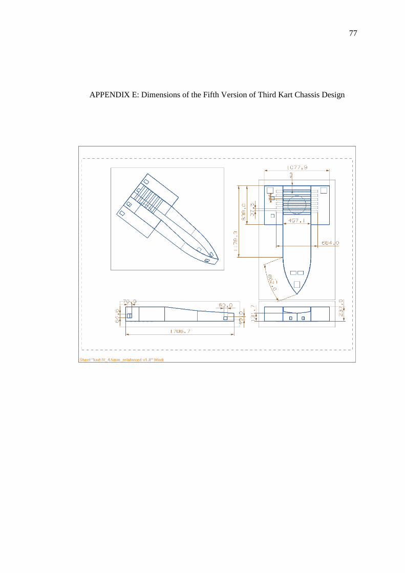
77
77
APPENDIX E: Dimensions of the Fifth Version of Third Kart Chassis Design

78
78
APPENDIX F: Ratio of Polyester Resin to Hardener
Prior to the fabrication of the go-kart, the mixing ratio of the polyester resin to
hardener is determined. Few experiments have been carried out to determine the
most suitable ratio that match with the fabrication conditions such as the surrounding
temperature and humidity. It is known that higher ratio would results in a faster gel
time. According to the definition by Net Composites (2008), the gel time is defined
as the time required for the flow-able liquid resin to change to non flowing gel.
Basically, from the experiments done, the ratio is found out to be in the range
of 100:1 to 100:3, which means that one to three percent of the hardener would work
well with the fabrication conditions in this project. Thus, the ratio of polyester resin
to hardener used was fixed at 100:1 throughout the whole fabrication process. For a
clearer explanation, 1 ml of hardener is mixed with every 100 ml of polyester resin
used. Besides, it is also discovered that the ratio of 100:1 would give a gel time of
around 30 minutes at the room temperature.