Embed Size (px)
Citation preview
Low Carbon Technology Project
Workstream 8
Vehicle Dynamics and Traction control for
Maximum Energy Recovery
Phil Barber
CENEX Technical review 19th May 2011
Overview of WS8
• Workstream 8 was set up to investigate and develop
Industrial methods needed to ensure the successful introduction of
braking systems that provide the optimal energy recovery from road
vehicles whilst maintaining the high levels of braking and stability
control performance.
Specifically, studies of
• Modelling and simulation
• Friction Brake re-design
• Prototype vehicle validation
(Rheostatic Braking)
• State of the Art review
(Competitor Benchmarking)
• Legislation
State of the Art Review
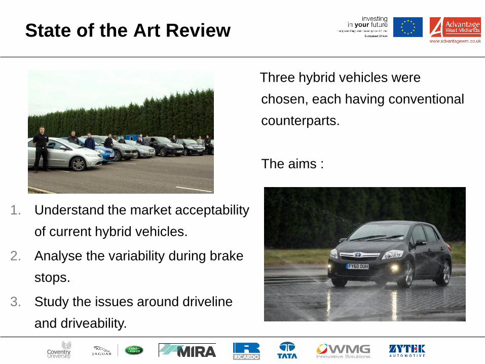
Three hybrid vehicles were
chosen, each having conventional
counterparts.
The aims :
1. Understand the market acceptability
of current hybrid vehicles.
2. Analyse the variability during brake
stops.
3. Study the issues around driveline
and driveability.
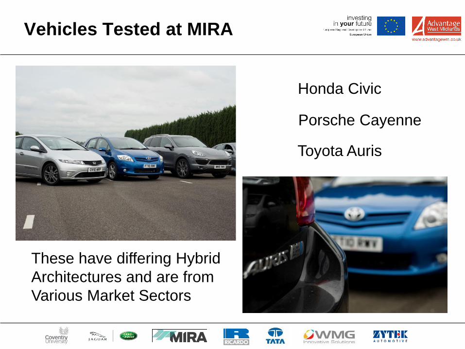
Vehicles Tested at MIRA
Toyota Auris
Honda Civic
Porsche Cayenne
These have differing Hybrid
Architectures and are from
Various Market Sectors
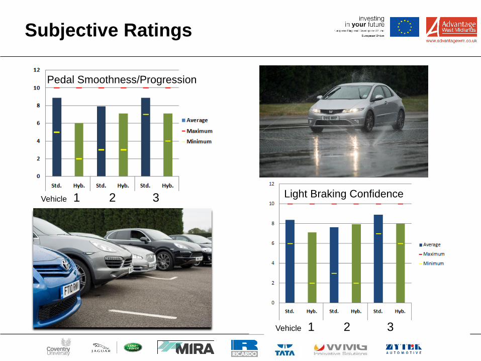
Subjective Ratings
Pedal Smoothness/Progression
Light Braking Confidence
Vehicle 1 2 3
Vehicle 1 2 3
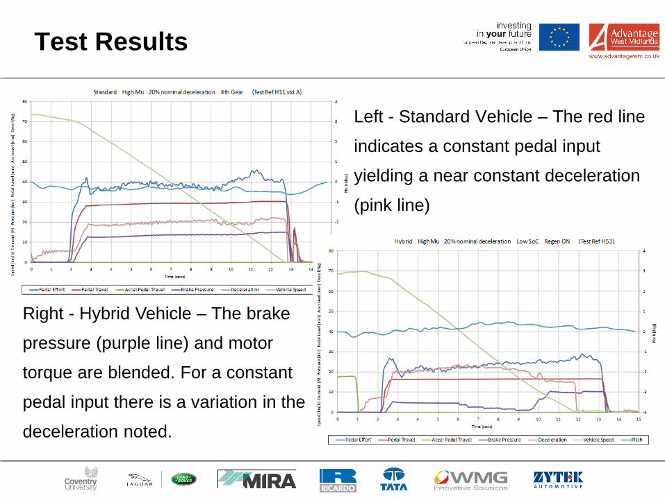
Test Results
Left - Standard Vehicle – The red line
indicates a constant pedal input
yielding a near constant deceleration
(pink line)
Right - Hybrid Vehicle – The brake
pressure (purple line) and motor
torque are blended. For a constant
pedal input there is a variation in the
deceleration noted.
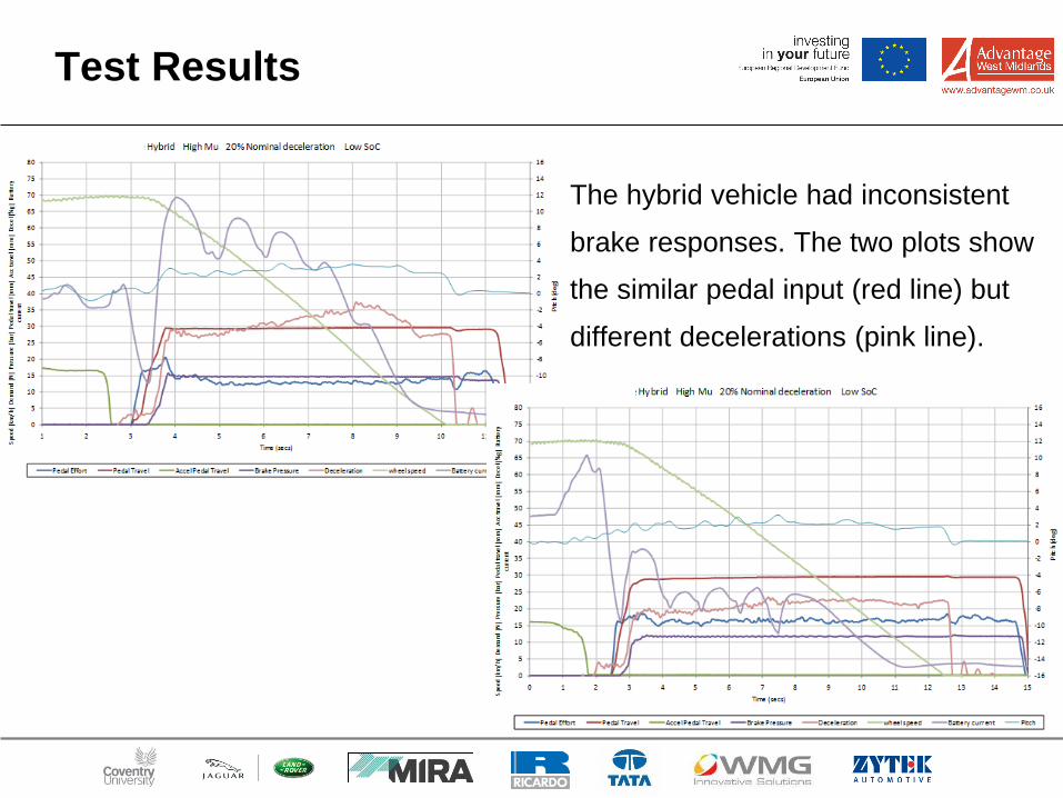
Test Results
The hybrid vehicle had inconsistent
brake responses. The two plots show
the similar pedal input (red line) but
different decelerations (pink line).
Legislative Requirements for
Regenerative Brake Systems.
EC/UNECE Brake Approvals.
In Europe the brake systems on new vehicles are required to be type approved to one of the following:
• European Directive 71/320/EEC as amended (last amendment 98/12/EC) or
• ECE Regulation 13H for Cars (M1) and optionally Light Commercials (N1) or
• ECE Regulation 13.11 for virtually all other vehicles
The Braking Directive was last revised before the widespread use of hybrid and electric vehicles
and, as a consequence, does not include the specific requirements that are now included in ECE
Regulation 13H and 13.11. A vehicle manufacturer is therefore able to sell vehicles that comply
with the Directive but not with the complex demands of the later regulations.
Types of Regen Systems in Reg 13H and 13.11
The regulation divides regenerative brake systems into 3 different types:
Category A
The electric regen system is not part of the brake system. Typically this means regen when the
throttle is released.
Category B Non-Phased
The electric regen system is part of the brake system. This means that regen commences or is
increased when the brake is applied. Electric regen force starts to be developed at the same time
as or slightly after the conventional friction brakes.
Category B Phased
The electric regen system is part of the brake system. Typically this means that regen forces can
be developed ahead of any braking from the conventional friction brakes. This system allows the
maximum amount of regen energy to be recovered.
Most regen brake systems operate both as a Category A system and Category B system under
different conditions.
Legislative Requirements for
Regenerative Brake Systems.
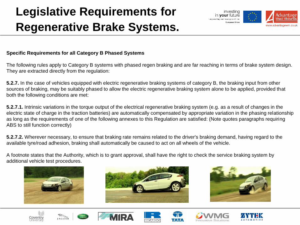
Specific Requirements for all Category B Phased Systems
The following rules apply to Category B systems with phased regen braking and are far reaching in terms of brake system design.
They are extracted directly from the regulation:
5.2.7. In the case of vehicles equipped with electric regenerative braking systems of category B, the braking input from other
sources of braking, may be suitably phased to allow the electric regenerative braking system alone to be applied, provided that
both the following conditions are met:
5.2.7.1. Intrinsic variations in the torque output of the electrical regenerative braking system (e.g. as a result of changes in the
electric state of charge in the traction batteries) are automatically compensated by appropriate variation in the phasing relationship
as long as the requirements of one of the following annexes to this Regulation are satisfied: (Note quotes paragraphs requiring
ABS to still function correctly)
5.2.7.2. Wherever necessary, to ensure that braking rate remains related to the driver's braking demand, having regard to the
available tyre/road adhesion, braking shall automatically be caused to act on all wheels of the vehicle.
A footnote states that the Authority, which is to grant approval, shall have the right to check the service braking system by
additional vehicle test procedures.
The Implications
The implications for Cat B systems with phased braked are significant. Phased braking means that regenerative braking (under the
control of the service brake system) can occur alone ahead of friction braking. Paragraph 5.2.7.1 means that the braking system
must automatically compensate for different states of battery charge. The driver must be given the same response to a braking
demand no matter what the state of charge of the batteries. Paragraph 5.2.7.2 means that if the axle with the regen braking system
hits a patch of ice, say, the friction brakes on the other axle must be automatically applied to an appropriate level such that the
driver’s expected deceleration is maintained (up until the limit of adhesion on both axles). These requirements have major
implications for the brake actuation system. It is no longer possible to use a conventional system. Power brake systems have been
used by most vehicle systems designed to meet these criteria. A few manufacturers have used increased functionality in the
stability control module, along with extra valves and a pedal simulator. Therefore to ensure maximum regen effectiveness on
electric and Hybrid vehicles complex brake control systems have to be used. This also means that brake homologation requires
additional complex work including analysis as well as tests.
Legislative Requirements for
Regenerative Brake Systems.
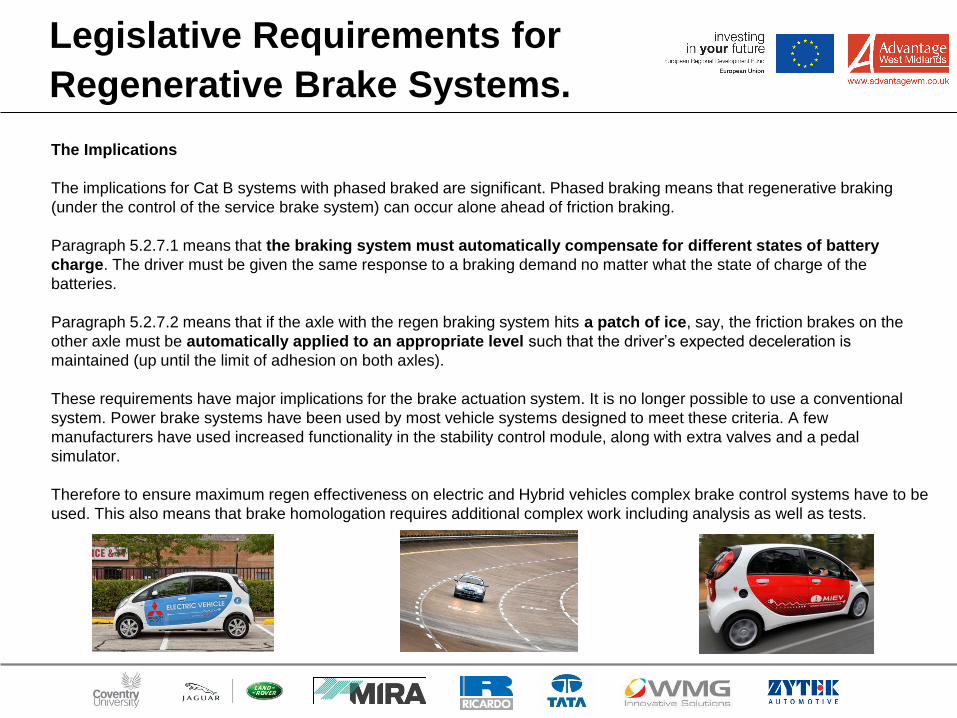
The Implications
The implications for Cat B systems with phased braked are significant. Phased braking means that regenerative braking
(under the control of the service brake system) can occur alone ahead of friction braking.
Paragraph 5.2.7.1 means that the braking system must automatically compensate for different states of battery
charge. The driver must be given the same response to a braking demand no matter what the state of charge of the
batteries.
Paragraph 5.2.7.2 means that if the axle with the regen braking system hits a patch of ice, say, the friction brakes on the
other axle must be automatically applied to an appropriate level such that the driver’s expected deceleration is
maintained (up until the limit of adhesion on both axles).
These requirements have major implications for the brake actuation system. It is no longer possible to use a conventional
system. Power brake systems have been used by most vehicle systems designed to meet these criteria. A few
manufacturers have used increased functionality in the stability control module, along with extra valves and a pedal
simulator.
Therefore to ensure maximum regen effectiveness on electric and Hybrid vehicles complex brake control systems have to be
used. This also means that brake homologation requires additional complex work including analysis as well as tests.
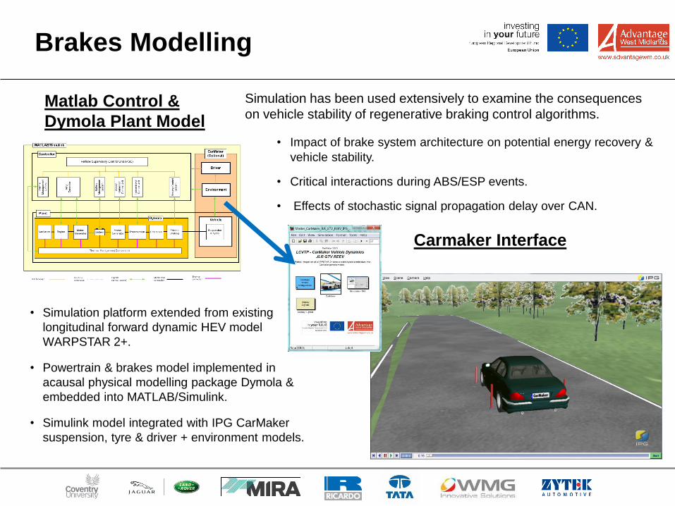
Matlab Control &
Dymola Plant Model
Carmaker Interface
Brakes Modelling
• Impact of brake system architecture on potential energy recovery &
vehicle stability.
• Critical interactions during ABS/ESP events.
• Effects of stochastic signal propagation delay over CAN.
• Simulation platform extended from existing
longitudinal forward dynamic HEV model
WARPSTAR 2+.
• Powertrain & brakes model implemented in
acausal physical modelling package Dymola &
embedded into MATLAB/Simulink.
• Simulink model integrated with IPG CarMaker
suspension, tyre & driver + environment models.
Simulation has been used extensively to examine the consequences
on vehicle stability of regenerative braking control algorithms.
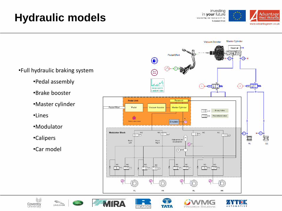
•Full hydraulic braking system
•Pedal assembly
•Brake booster
•Master cylinder
•Lines
•Modulator
•Calipers
•Car model
Hydraulic models
Brakes Modelling
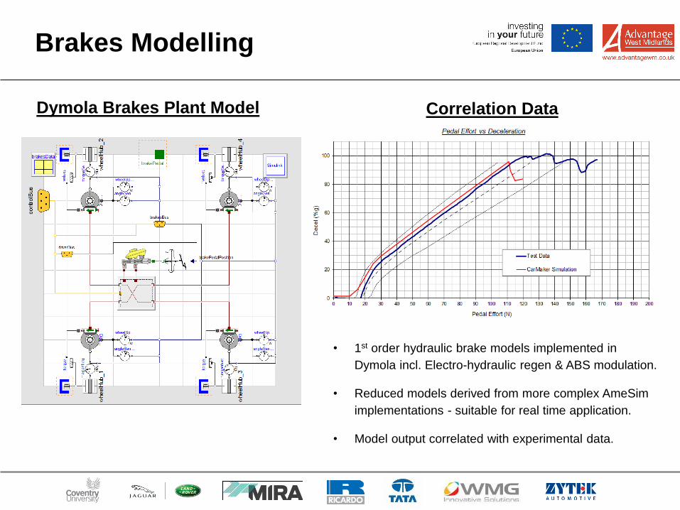
Dymola Brakes Plant Model Correlation Data
• 1st order hydraulic brake models implemented in
Dymola incl. Electro-hydraulic regen & ABS modulation.
• Reduced models derived from more complex AmeSim
implementations - suitable for real time application.
• Model output correlated with experimental data.
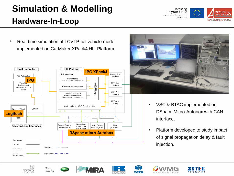
• Real-time simulation of LCVTP full vehicle model
implemented on CarMaker XPack4 HIL Platform
Simulation & Modelling
Hardware-In-Loop
• VSC & BTAC implemented on
DSpace Micro-Autobox with CAN
interface.
• Platform developed to study impact
of signal propagation delay & fault
injection.
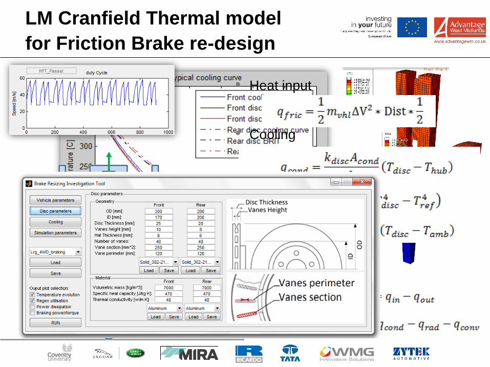
LM Cranfield Thermal model
for Friction Brake re-design
• Heat input
• Cooling
• Energy balance
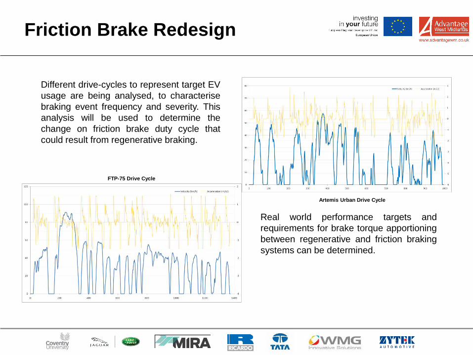
Friction Brake Redesign
Different drive-cycles to represent target EV
usage are being analysed, to characterise
braking event frequency and severity. This
analysis will be used to determine the
change on friction brake duty cycle that
could result from regenerative braking.
FTP-75 Drive Cycle
Artemis Urban Drive Cycle
Real world performance targets and
requirements for brake torque apportioning
between regenerative and friction braking
systems can be determined.
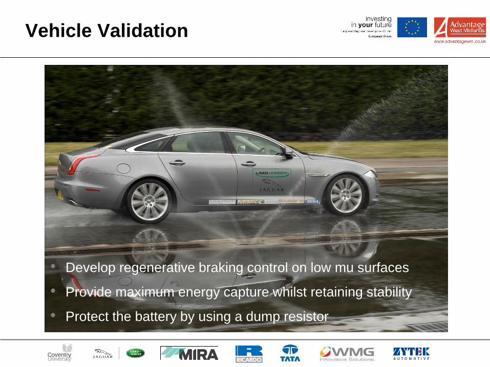
Vehicle Validation
• Develop regenerative braking control on low mu surfaces
• Provide maximum energy capture whilst retaining stability
• Protect the battery by using a dump resistor
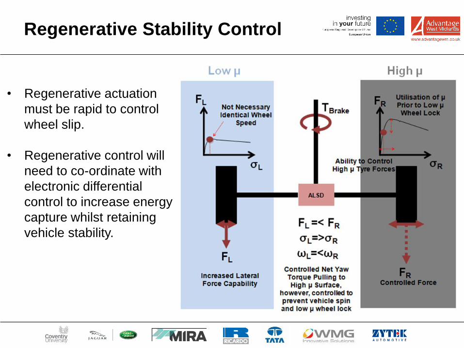
Regenerative Stability Control
• Regenerative actuation
must be rapid to control
wheel slip.
• Regenerative control will
need to co-ordinate with
electronic differential
control to increase energy
capture whilst retaining
vehicle stability.
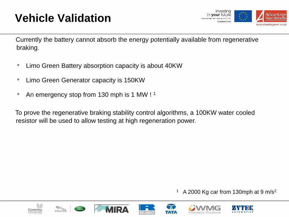
Vehicle Validation
Currently the battery cannot absorb the energy potentially available from regenerative
braking.
1 A 2000 Kg car from 130mph at 9 m/s2
• Limo Green Battery absorption capacity is about 40KW
• Limo Green Generator capacity is 150KW
• An emergency stop from 130 mph is 1 MW ! 1
To prove the regenerative braking stability control algorithms, a 100KW water cooled
resistor will be used to allow testing at high regeneration power.
Conclusions
• The majority of brake events in a vehicle’s lifetime could theoretically be performed
through use of regenerative braking.
• Although the friction brake / stability control system cannot be completely replaced, this
raises the question of how it could be redesigned and optimised to take advantage of
regenerative braking, and engineered to better suit the real-life use seen in an EV
powertrain.
• Suitability of different powertain configurations is a key factor in determining
regenerative braking capabilities. On a front wheel drive vehicle almost all of the
braking seen in typical city-driving could conceivably be regenerative.
On Going Work:
• Consolidation of the modelling toolset to allow the quantitative assessment of different
braking architectures.
• Validation of the stability control concepts in high energy regenerative braking
scenarios.