Embed Size (px)
Citation preview
Part Number: A702T0002A
Version: 6
Exige V6 Cup Car Supplementary Manual
- 1 -
Lotus Racing Exige V6 Cup Car
Supplementary Manual VINs: SCCLKHSC4DHD10447 Onwards
All data and instructions in this Supplementary Manual
take precedence over material in the Owner's Handbook.
Technical Data
Supplementary to Workshop Manual A138T0327 Supplementary to Parts Manual A138T0325
Issue number: 006
Issue date: 15TH NOVEMBER 2013
Lotus Racing contact details: -
Lotus Racing Lotus Cars Ltd Potash Lane
Hethel Norwich
Norfolk, UK NR14 8EZ
Part Number: A702T0002A
Version: 6
Exige V6 Cup Car Supplementary Manual
- 2 -
Welcome to Lotus Racing
Everyone at Lotus Racing would like to thank you and congratulate you on your choice of a Lotus Exige V6 Cup Car. The Exige Cup range was developed to allow Lotus enthusiasts to expand their driving activities beyond the standard road car.
Over the last 10 years Exige V6 Cup Cars have been entered into numerous track days, club racing activities and even tarmac rallycross events (once suitable upgrades are fitted).
Each car is developed by hand in our factory based workshop by our highly skilled technicians. Only factory produced cars can proudly display a Lotus Racing build plate.
This Supplementary Manual to the Owner’s Handbook has been produced to provide you with important information on operating and maintaining your Exige V6 Cup car. Please read it carefully, in conjunction with the standard Owner’s Handbook supplied, before using the vehicle.
Lotus Racing wishes you many enjoyable driving days with your car and look forward to receiving your news of ‘Cup’ adventures.
Thank you once again
R Manwaring, Director and all at Lotus Racing IN CASE OF CONFLICT BETWEN THIS SUPPLEMENTARY MANUAL AND THE STANDARD OWNERS HANDBOOK, THIS SUPPLEMENTARY MANUAL SHALL CONTROL. PLEASE CONTACT YOUR LOCAL DEALER OR LOTUS RACING IF ANY EXPLANATION OR CLARIFICATION IS REQUIRED.
Part Number: A702T0002A
Version: 6
Exige V6 Cup Car Supplementary Manual
- 3 -
CONTENTS
1.0 LEGAL, SAFETY AND WARRANTY ISSUES ........................................................................... 4
1.1 Important Safety Information.................................................................................................................................................... 4 1.2 Warranty & Disclaimer ............................................................................................................................................................. 5
2.0 ADDITIONAL PARTS (INCLUDING OPTIONS)......................................................................... 6
2.1 Nitron Dampers......................................................................................................................................................................... 6 2.2 Fluids......................................................................................................................................................................................... 7 2.3 Catch Tank ................................................................................................................................................................................ 7 2.4 Wheels and Tyres...................................................................................................................................................................... 7 2.5 Tyre Pressures and Tyre Life .................................................................................................................................................... 8 2.6 Brakes ....................................................................................................................................................................................... 8 2.7 Fire Extinguisher....................................................................................................................................................................... 9 2.8 Battery Master Switch............................................................................................................................................................. 10 2.9 Lotus Racing Build Plate ........................................................................................................................................................ 10 2.10 Removable Steering Wheel..................................................................................................................................................... 10 2.11 Roll Cage Removal/Refitting (Optional Component) ............................................................................................................. 11 2.12 Front and Rear Towing Eyes................................................................................................................................................... 12 2.13 Baffled Sump .......................................................................................................................................................................... 12 2.14 Interior Trim............................................................................................................................................................................ 13 2.15 Drivers and Passenger Seat Belt Harness................................................................................................................................ 13
3.0 DELETED ITEMS...................................................................................................................... 15
3.1 Security Features..................................................................................................................................................................... 15 3.2 Hard Trim................................................................................................................................................................................ 15 3.3 Radio ....................................................................................................................................................................................... 15
4.0 PARTS LIST ............................................................................................................................. 16
5.0 SUSPENSION SETTINGS........................................................................................................ 19
6.0 BRAKE PAD BEDDING IN PROCEDURE ............................................................................... 20
7.0 VEHICLE RUNNING IN ............................................................................................................ 21
8.0 SERVICE GUIDE ...................................................................................................................... 22
9.0 ELECTRICAL CIRCUITS.......................................................................................................... 27
NOTE: This manual is written for the experienced track enthusiast; proper experience is necessary to both understand this manual and operate the Exige V6 Cup Car.
Part Number: A702T0002A
Version: 6
Exige V6 Cup Car Supplementary Manual
- 4 -
1.0 LEGAL, SAFETY AND WARRANTY ISSUES
1.1 Important Safety Information
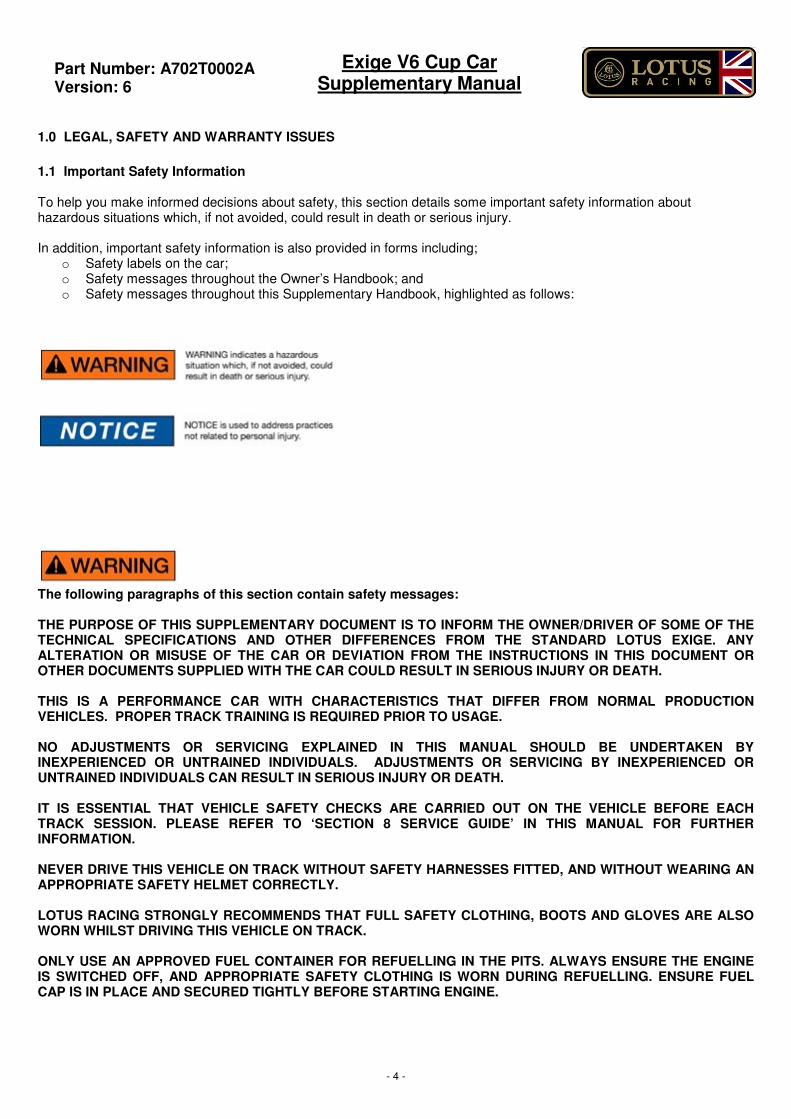
To help you make informed decisions about safety, this section details some important safety information about hazardous situations which, if not avoided, could result in death or serious injury. In addition, important safety information is also provided in forms including;
o Safety labels on the car; o Safety messages throughout the Owner’s Handbook; and o Safety messages throughout this Supplementary Handbook, highlighted as follows:
The following paragraphs of this section contain safety messages: THE PURPOSE OF THIS SUPPLEMENTARY DOCUMENT IS TO INFORM THE OWNER/DRIVER OF SOME OF THE TECHNICAL SPECIFICATIONS AND OTHER DIFFERENCES FROM THE STANDARD LOTUS EXIGE. ANY ALTERATION OR MISUSE OF THE CAR OR DEVIATION FROM THE INSTRUCTIONS IN THIS DOCUMENT OR OTHER DOCUMENTS SUPPLIED WITH THE CAR COULD RESULT IN SERIOUS INJURY OR DEATH. THIS IS A PERFORMANCE CAR WITH CHARACTERISTICS THAT DIFFER FROM NORMAL PRODUCTION VEHICLES. PROPER TRACK TRAINING IS REQUIRED PRIOR TO USAGE. NO ADJUSTMENTS OR SERVICING EXPLAINED IN THIS MANUAL SHOULD BE UNDERTAKEN BY INEXPERIENCED OR UNTRAINED INDIVIDUALS. ADJUSTMENTS OR SERVICING BY INEXPERIENCED OR UNTRAINED INDIVIDUALS CAN RESULT IN SERIOUS INJURY OR DEATH. IT IS ESSENTIAL THAT VEHICLE SAFETY CHECKS ARE CARRIED OUT ON THE VEHICLE BEFORE EACH TRACK SESSION. PLEASE REFER TO ‘SECTION 8 SERVICE GUIDE’ IN THIS MANUAL FOR FURTHER INFORMATION. NEVER DRIVE THIS VEHICLE ON TRACK WITHOUT SAFETY HARNESSES FITTED, AND WITHOUT WEARING AN APPROPRIATE SAFETY HELMET CORRECTLY. LOTUS RACING STRONGLY RECOMMENDS THAT FULL SAFETY CLOTHING, BOOTS AND GLOVES ARE ALSO WORN WHILST DRIVING THIS VEHICLE ON TRACK. ONLY USE AN APPROVED FUEL CONTAINER FOR REFUELLING IN THE PITS. ALWAYS ENSURE THE ENGINE IS SWITCHED OFF, AND APPROPRIATE SAFETY CLOTHING IS WORN DURING REFUELLING. ENSURE FUEL CAP IS IN PLACE AND SECURED TIGHTLY BEFORE STARTING ENGINE.
Part Number: A702T0002A
Version: 6
Exige V6 Cup Car Supplementary Manual
- 5 -
1.2 Warranty & Disclaimer Please note that some of the technical data included in this document refers to options that may not be fitted to your specific vehicle. Although we have made every effort to ensure that the particulars contained in this manual are correct we cannot guarantee the accuracy of the information. Neither the manufacturer nor the distributor or dealer shall in any circumstances be held liable for any inaccuracy of any information or illustrations. Lotus reserves the right to change any product specifications at any time without notice or incurring obligation. Descriptions and images in this manual may describe or depict equipment that may not be available in all markets around the world or may be optional equipment. All information presented herein is based on data available at the time of printing and is subject to change without notice. The vehicle owner is responsible for ensuring their vehicle complies with their respective race and / or track regulations. Purchaser assumes all risks of using this vehicle on the track or in racing events.
Warranty The Warranty provided by Lotus on this vehicle comprises (1) an 8 year unlimited mileage chassis anti-corrosion warranty, and (2) a one year or (6,000m/9,600Km) (whichever occurs first), defect warranty excluding consumable parts. Page 5 of the New Vehicle Warranty booklet is therefore amended as necessary to reflect this warranty. Intended Purpose The Exige V6 Cup Car is intended for use as a road going passenger car and for use in non-competition track day events. USE IN A COMPETITIVE MANNER, INCLUDING TIMED LAPS OR RUNS WILL INVALIDATE THE NEW VEHICLE WARRANTY. Participation in track day events other than competitive events or timed laps or runs will not invalidate the New Vehicle Warranty, unless the vehicle is hired to participate in such events on a commercial basis. The manufacturers warranty is in addition to any legal rights you may have in relation to the car under the law of the country in which you purchased it.
Part Number: A702T0002A
Version: 6
Exige V6 Cup Car Supplementary Manual
- 6 -
2.0 ADDITIONAL PARTS (INCLUDING OPTIONS)
The Lotus Racing Exige V6 Cup car is fitted with the following equipment that differs from the standard Exige. Lotus reserves the right to change any product specifications at any time without notice or incurring obligation. Descriptions and images in this manual may describe or depict equipment that may not be available in all markets around the world or may be optional equipment. All information presented herein is based on data available at the time of printing and is subject to change without notice.
THE EXIGE V6 CUP CAR IS A HIGH PERFORMANCE TRACK CAR. IT NEITHER HAS THE SAME EQUIPMENT AS A PASSENGER CAR NOR HAS THE SAME HANDLING CHARACTERISTICS. IT IS IMPERATIVE THAT YOU HAVE PROPER INSTRUCTION ON OPERATION TO ENSURE A SAFE AND ENJOYABLE EXPERIENCE. ALWAYS WEAR A HELMET WHEN DRIVING ON TRACK AND BUCKLE YOUR SEAT BELT HARNESS. 2.1 Nitron Dampers The Nitron Dampers as fitted to the Lotus Racing Exige V6 Cup Cars are two way adjustable in Compression (Bump) and in Rebound, thus offering a greater tuning potential than a standard damper.
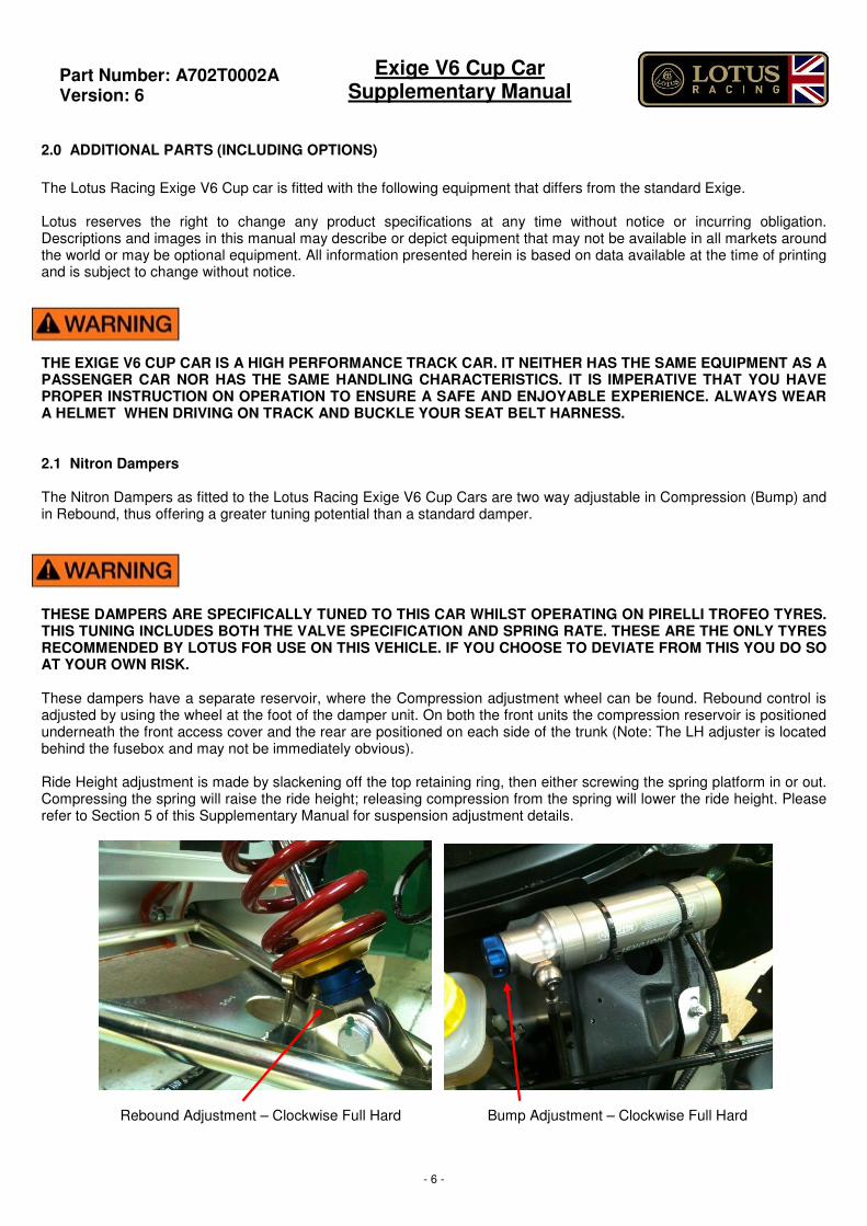
THESE DAMPERS ARE SPECIFICALLY TUNED TO THIS CAR WHILST OPERATING ON PIRELLI TROFEO TYRES. THIS TUNING INCLUDES BOTH THE VALVE SPECIFICATION AND SPRING RATE. THESE ARE THE ONLY TYRES RECOMMENDED BY LOTUS FOR USE ON THIS VEHICLE. IF YOU CHOOSE TO DEVIATE FROM THIS YOU DO SO AT YOUR OWN RISK. These dampers have a separate reservoir, where the Compression adjustment wheel can be found. Rebound control is adjusted by using the wheel at the foot of the damper unit. On both the front units the compression reservoir is positioned underneath the front access cover and the rear are positioned on each side of the trunk (Note: The LH adjuster is located behind the fusebox and may not be immediately obvious). Ride Height adjustment is made by slackening off the top retaining ring, then either screwing the spring platform in or out. Compressing the spring will raise the ride height; releasing compression from the spring will lower the ride height. Please refer to Section 5 of this Supplementary Manual for suspension adjustment details.
Rebound Adjustment – Clockwise Full Hard Bump Adjustment – Clockwise Full Hard
Part Number: A702T0002A
Version: 6
Exige V6 Cup Car Supplementary Manual
- 7 -
2.2 Fluids The fluids used on the Lotus Racing Exige Cup Car remain the same as shown in the Owner’s Handbook.
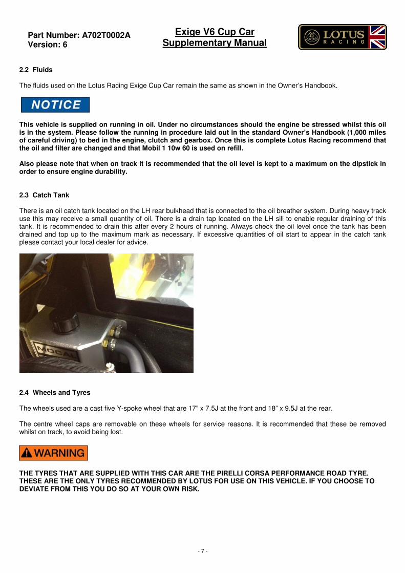
This vehicle is supplied on running in oil. Under no circumstances should the engine be stressed whilst this oil is in the system. Please follow the running in procedure laid out in the standard Owner’s Handbook (1,000 miles of careful driving) to bed in the engine, clutch and gearbox. Once this is complete Lotus Racing recommend that the oil and filter are changed and that Mobil 1 10w 60 is used on refill. Also please note that when on track it is recommended that the oil level is kept to a maximum on the dipstick in order to ensure engine durability. 2.3 Catch Tank There is an oil catch tank located on the LH rear bulkhead that is connected to the oil breather system. During heavy track use this may receive a small quantity of oil. There is a drain tap located on the LH sill to enable regular draining of this tank. It is recommended to drain this after every 2 hours of running. Always check the oil level once the tank has been drained and top up to the maximum mark as necessary. If excessive quantities of oil start to appear in the catch tank please contact your local dealer for advice.
2.4 Wheels and Tyres The wheels used are a cast five Y-spoke wheel that are 17” x 7.5J at the front and 18” x 9.5J at the rear. The centre wheel caps are removable on these wheels for service reasons. It is recommended that these be removed whilst on track, to avoid being lost.
THE TYRES THAT ARE SUPPLIED WITH THIS CAR ARE THE PIRELLI CORSA PERFORMANCE ROAD TYRE. THESE ARE THE ONLY TYRES RECOMMENDED BY LOTUS FOR USE ON THIS VEHICLE. IF YOU CHOOSE TO DEVIATE FROM THIS YOU DO SO AT YOUR OWN RISK.
Part Number: A702T0002A
Version: 6
Exige V6 Cup Car Supplementary Manual
- 8 -
2.5 Tyre Pressures and Tyre Life Tyre operating pressures should be varied to each individual circuit in order to obtain the optimum performance. Initial recommendations for tyre pressures are: Front Tyre 29 PSI COLD (WEATHER DEPENDENT) Rear Tyre 26 PSI COLD (WEATHER DEPENDENT) Front Tyre 32 PSI HOT Rear Tyre 38 PSI HOT Note: This is dependent upon camber/toe and ambient and track temperature conditions, and should be adjusted to suit particular conditions. Tyre operating data can be found in the Owner’s Handbook, supplied with the car.
FAILURE TO MAINTAIN PROPER TYRE PRESSURE AND TYRE CARE CAN LEAD TO SERIOUS INJURY OR DEATH 2.6 Brakes The front and rear brake discs are uprated to sports specification for increased track performance. Please be aware that discs used on racing circuits and/or test tracks will be subject to higher temperatures and wear rates than achieved with normal road use. This can have an effect on the life of the disc, especially when high friction competition pads are used. Discs along with pads are consumable items, and service life will vary, depending on driving style and vehicle use. DISCS MUST BE REGULARLY AND FREQUENTLY INSPECTED FOR EXCESSIVE HEAT CRAZING AND CRACKING. DISCS WITH CRACKS EMANATING FROM MOUNTING HOLES / SLOTS, INSIDE DIAMETER, SCALLOPS, OR OUTSIDE DIAMETER SHOULD BE CHANGED IMMEDIATELY. AFTER HEAVY AND PROLONGED USE SOME SURFACE CRAZING WILL OFTEN BE EVIDENT. IF THIS TURNS INTO DISTINCT SURFACE CRACKS RADIATING TOWARDS THE INSIDE OR OUTSIDE DIAMETER, THE DISC SHOULD BE CHANGED. IF IN DOUBT, REPLACE! ALL CAST IRON BRAKE DISCS NEED TO BE BEDDED-IN TO ENSURE HEAT STABILIZATION AND IMPROVE RESISTANCE TO CRACKING. CRACKS OR EVEN DISC FAILURE CAN OCCUR DURING THE FIRST FEW HEAVY STOPS IF CAREFUL BEDDING IS NOT CARRIED OUT. If pads are not bedded properly and / or are used too hard right out of the box, it is likely to lead to pad glazing. Pad glazing is a condition where the resins in the pad crystallize on both the pad friction surface and the brake disc surface, resulting in poor stopping performance, brake judder and vibrations. Also rapidly escaping volatile elements and moisture from the resin would seek an immediate escape route out of the friction compound, creating small fissures that would lead shortly to cracking and chunking. See Section 6 for proper bedding in procedure.
Part Number: A702T0002A
Version: 6
Exige V6 Cup Car Supplementary Manual
- 9 -
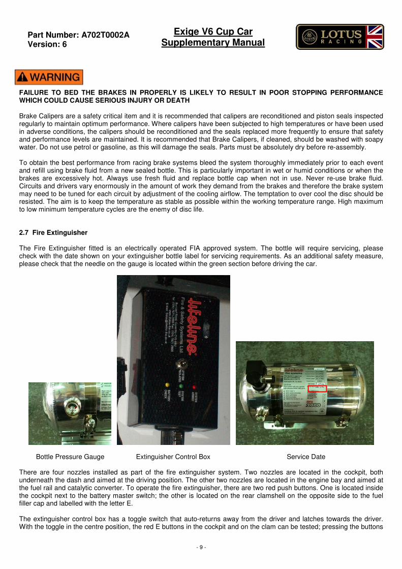
FAILURE TO BED THE BRAKES IN PROPERLY IS LIKELY TO RESULT IN POOR STOPPING PERFORMANCE WHICH COULD CAUSE SERIOUS INJURY OR DEATH Brake Calipers are a safety critical item and it is recommended that calipers are reconditioned and piston seals inspected regularly to maintain optimum performance. Where calipers have been subjected to high temperatures or have been used in adverse conditions, the calipers should be reconditioned and the seals replaced more frequently to ensure that safety and performance levels are maintained. It is recommended that Brake Calipers, if cleaned, should be washed with soapy water. Do not use petrol or gasoline, as this will damage the seals. Parts must be absolutely dry before re-assembly. To obtain the best performance from racing brake systems bleed the system thoroughly immediately prior to each event and refill using brake fluid from a new sealed bottle. This is particularly important in wet or humid conditions or when the brakes are excessively hot. Always use fresh fluid and replace bottle cap when not in use. Never re-use brake fluid. Circuits and drivers vary enormously in the amount of work they demand from the brakes and therefore the brake system may need to be tuned for each circuit by adjustment of the cooling airflow. The temptation to over cool the disc should be resisted. The aim is to keep the temperature as stable as possible within the working temperature range. High maximum to low minimum temperature cycles are the enemy of disc life. 2.7 Fire Extinguisher The Fire Extinguisher fitted is an electrically operated FIA approved system. The bottle will require servicing, please check with the date shown on your extinguisher bottle label for servicing requirements. As an additional safety measure, please check that the needle on the gauge is located within the green section before driving the car.
Bottle Pressure Gauge Extinguisher Control Box Service Date There are four nozzles installed as part of the fire extinguisher system. Two nozzles are located in the cockpit, both underneath the dash and aimed at the driving position. The other two nozzles are located in the engine bay and aimed at the fuel rail and catalytic converter. To operate the fire extinguisher, there are two red push buttons. One is located inside the cockpit next to the battery master switch; the other is located on the rear clamshell on the opposite side to the fuel filler cap and labelled with the letter E. The extinguisher control box has a toggle switch that auto-returns away from the driver and latches towards the driver. With the toggle in the centre position, the red E buttons in the cockpit and on the clam can be tested; pressing the buttons
Part Number: A702T0002A
Version: 6
Exige V6 Cup Car Supplementary Manual
- 10 -
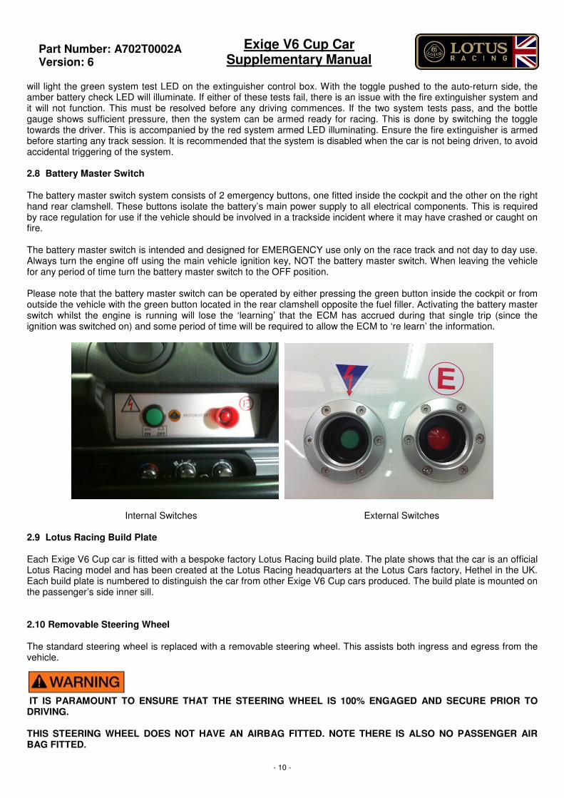
will light the green system test LED on the extinguisher control box. With the toggle pushed to the auto-return side, the amber battery check LED will illuminate. If either of these tests fail, there is an issue with the fire extinguisher system and it will not function. This must be resolved before any driving commences. If the two system tests pass, and the bottle gauge shows sufficient pressure, then the system can be armed ready for racing. This is done by switching the toggle towards the driver. This is accompanied by the red system armed LED illuminating. Ensure the fire extinguisher is armed before starting any track session. It is recommended that the system is disabled when the car is not being driven, to avoid accidental triggering of the system. 2.8 Battery Master Switch The battery master switch system consists of 2 emergency buttons, one fitted inside the cockpit and the other on the right hand rear clamshell. These buttons isolate the battery’s main power supply to all electrical components. This is required by race regulation for use if the vehicle should be involved in a trackside incident where it may have crashed or caught on fire. The battery master switch is intended and designed for EMERGENCY use only on the race track and not day to day use. Always turn the engine off using the main vehicle ignition key, NOT the battery master switch. When leaving the vehicle for any period of time turn the battery master switch to the OFF position. Please note that the battery master switch can be operated by either pressing the green button inside the cockpit or from outside the vehicle with the green button located in the rear clamshell opposite the fuel filler. Activating the battery master switch whilst the engine is running will lose the ‘learning’ that the ECM has accrued during that single trip (since the ignition was switched on) and some period of time will be required to allow the ECM to ‘re learn’ the information.
Internal Switches External Switches 2.9 Lotus Racing Build Plate Each Exige V6 Cup car is fitted with a bespoke factory Lotus Racing build plate. The plate shows that the car is an official Lotus Racing model and has been created at the Lotus Racing headquarters at the Lotus Cars factory, Hethel in the UK. Each build plate is numbered to distinguish the car from other Exige V6 Cup cars produced. The build plate is mounted on the passenger’s side inner sill. 2.10 Removable Steering Wheel The standard steering wheel is replaced with a removable steering wheel. This assists both ingress and egress from the vehicle. IT IS PARAMOUNT TO ENSURE THAT THE STEERING WHEEL IS 100% ENGAGED AND SECURE PRIOR TO DRIVING. THIS STEERING WHEEL DOES NOT HAVE AN AIRBAG FITTED. NOTE THERE IS ALSO NO PASSENGER AIR BAG FITTED.
Part Number: A702T0002A
Version: 6
Exige V6 Cup Car Supplementary Manual
- 11 -
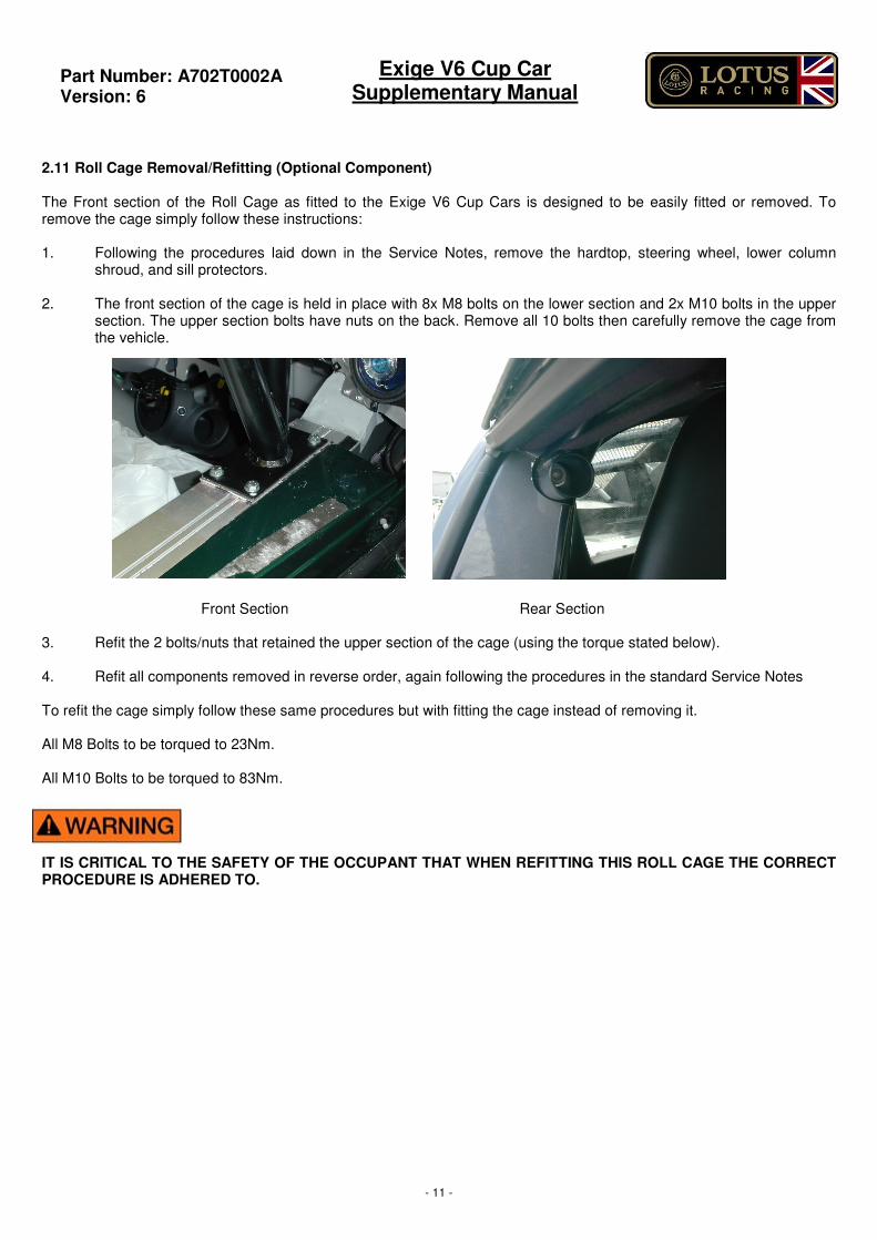
2.11 Roll Cage Removal/Refitting (Optional Component) The Front section of the Roll Cage as fitted to the Exige V6 Cup Cars is designed to be easily fitted or removed. To remove the cage simply follow these instructions: 1. Following the procedures laid down in the Service Notes, remove the hardtop, steering wheel, lower column
shroud, and sill protectors. 2. The front section of the cage is held in place with 8x M8 bolts on the lower section and 2x M10 bolts in the upper
section. The upper section bolts have nuts on the back. Remove all 10 bolts then carefully remove the cage from the vehicle.
Front Section Rear Section 3. Refit the 2 bolts/nuts that retained the upper section of the cage (using the torque stated below). 4. Refit all components removed in reverse order, again following the procedures in the standard Service Notes To refit the cage simply follow these same procedures but with fitting the cage instead of removing it. All M8 Bolts to be torqued to 23Nm. All M10 Bolts to be torqued to 83Nm. IT IS CRITICAL TO THE SAFETY OF THE OCCUPANT THAT WHEN REFITTING THIS ROLL CAGE THE CORRECT PROCEDURE IS ADHERED TO.
Part Number: A702T0002A
Version: 6
Exige V6 Cup Car Supplementary Manual
- 12 -
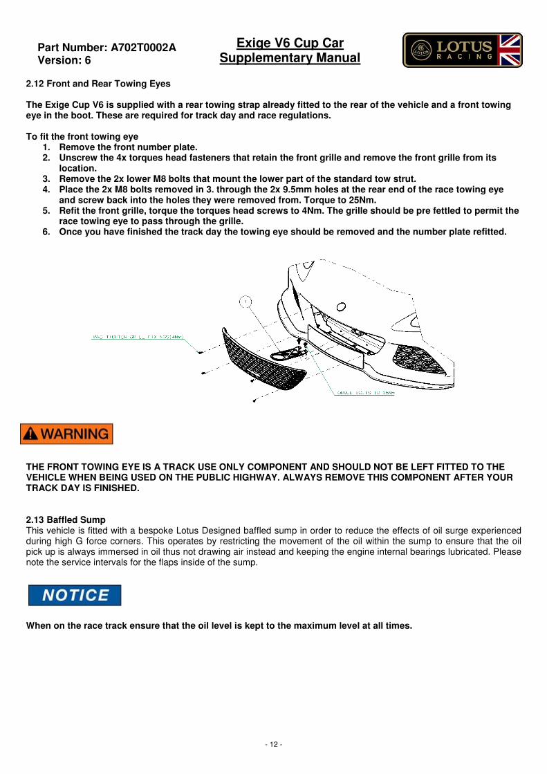
2.12 Front and Rear Towing Eyes The Exige Cup V6 is supplied with a rear towing strap already fitted to the rear of the vehicle and a front towing eye in the boot. These are required for track day and race regulations. To fit the front towing eye
1. Remove the front number plate. 2. Unscrew the 4x torques head fasteners that retain the front grille and remove the front grille from its
location. 3. Remove the 2x lower M8 bolts that mount the lower part of the standard tow strut. 4. Place the 2x M8 bolts removed in 3. through the 2x 9.5mm holes at the rear end of the race towing eye
and screw back into the holes they were removed from. Torque to 25Nm. 5. Refit the front grille, torque the torques head screws to 4Nm. The grille should be pre fettled to permit the
race towing eye to pass through the grille. 6. Once you have finished the track day the towing eye should be removed and the number plate refitted.
THE FRONT TOWING EYE IS A TRACK USE ONLY COMPONENT AND SHOULD NOT BE LEFT FITTED TO THE VEHICLE WHEN BEING USED ON THE PUBLIC HIGHWAY. ALWAYS REMOVE THIS COMPONENT AFTER YOUR TRACK DAY IS FINISHED.
2.13 Baffled Sump This vehicle is fitted with a bespoke Lotus Designed baffled sump in order to reduce the effects of oil surge experienced during high G force corners. This operates by restricting the movement of the oil within the sump to ensure that the oil pick up is always immersed in oil thus not drawing air instead and keeping the engine internal bearings lubricated. Please note the service intervals for the flaps inside of the sump.
When on the race track ensure that the oil level is kept to the maximum level at all times.
Part Number: A702T0002A
Version: 6
Exige V6 Cup Car Supplementary Manual
- 13 -
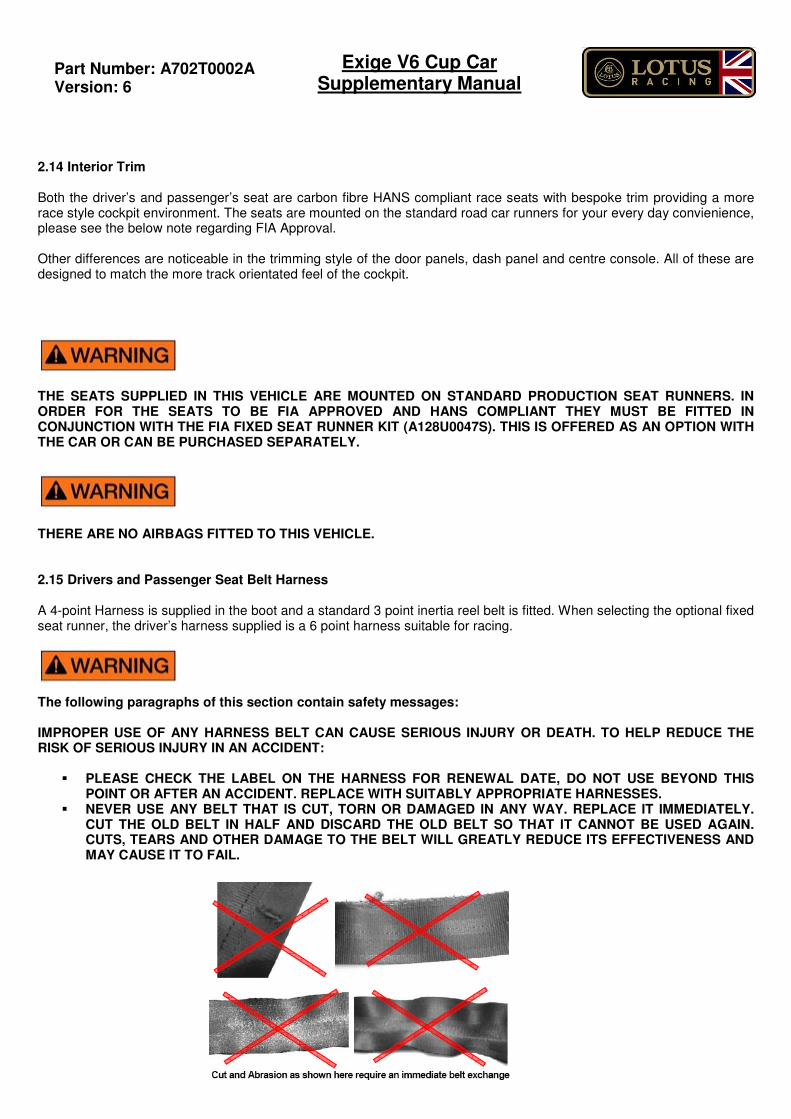
2.14 Interior Trim Both the driver’s and passenger’s seat are carbon fibre HANS compliant race seats with bespoke trim providing a more race style cockpit environment. The seats are mounted on the standard road car runners for your every day convienience, please see the below note regarding FIA Approval. Other differences are noticeable in the trimming style of the door panels, dash panel and centre console. All of these are designed to match the more track orientated feel of the cockpit. THE SEATS SUPPLIED IN THIS VEHICLE ARE MOUNTED ON STANDARD PRODUCTION SEAT RUNNERS. IN ORDER FOR THE SEATS TO BE FIA APPROVED AND HANS COMPLIANT THEY MUST BE FITTED IN CONJUNCTION WITH THE FIA FIXED SEAT RUNNER KIT (A128U0047S). THIS IS OFFERED AS AN OPTION WITH THE CAR OR CAN BE PURCHASED SEPARATELY. THERE ARE NO AIRBAGS FITTED TO THIS VEHICLE. 2.15 Drivers and Passenger Seat Belt Harness A 4-point Harness is supplied in the boot and a standard 3 point inertia reel belt is fitted. When selecting the optional fixed seat runner, the driver’s harness supplied is a 6 point harness suitable for racing.
The following paragraphs of this section contain safety messages: IMPROPER USE OF ANY HARNESS BELT CAN CAUSE SERIOUS INJURY OR DEATH. TO HELP REDUCE THE RISK OF SERIOUS INJURY IN AN ACCIDENT:
� PLEASE CHECK THE LABEL ON THE HARNESS FOR RENEWAL DATE, DO NOT USE BEYOND THIS POINT OR AFTER AN ACCIDENT. REPLACE WITH SUITABLY APPROPRIATE HARNESSES.
� NEVER USE ANY BELT THAT IS CUT, TORN OR DAMAGED IN ANY WAY. REPLACE IT IMMEDIATELY. CUT THE OLD BELT IN HALF AND DISCARD THE OLD BELT SO THAT IT CANNOT BE USED AGAIN. CUTS, TEARS AND OTHER DAMAGE TO THE BELT WILL GREATLY REDUCE ITS EFFECTIVENESS AND MAY CAUSE IT TO FAIL.
Part Number: A702T0002A
Version: 6
Exige V6 Cup Car Supplementary Manual
- 14 -
� NEVER STRAP MORE THAN ONE PERSON IN PLACE WITH EACH HARNESS BELT. � NEVER USE THE HARNESS BELT SYSTEM FOR PERSONS WHO WEIGH LESS THAN 40 KG (88 LBS) OR
THOSE WHO ARE LESS THAN 150 CM (4‘11“) TALL, REGARDLESS OF AGE. � NEVER USE THE LAP BELT PORTION OF THE HARNESS BELT WITHOUT THE SHOULDER BELTS. � ALL STRAPS MUST PERMANENTLY RUN THROUGH THE SLOTS OF THE BUCKET SEAT. � ALWAYS MAKE SURE THAT NO STRAP IS TWISTED WHEN WORN. � ALWAYS WEAR THE LAP BELT PORTION OF THE HARNESS SYSTEM LOW AND TIGHT ACROSS THE
PELVIS. � PRESSURE OF SHOULDER BELTS ON YOUR SHOULDER AND CHEST MUST BE EQUAL. � NEVER WEAR THE BELTS OVER HEAVY CLOTHING AS IT CAN INTERFERE WITH PROPER
POSITIONING AND ADJUSTMENT OF THE BELTS, REDUCING THE OVERALL EFFECTIVENESS OF THE SYSTEM.
� NEVER WEAR THE BELTS OVER RIGID OR BREAKABLE OBJECTS IN OR ON YOUR CLOTHING, SUCH AS EYE GLASSES, PENS, JEWELRY, KEYS ETC AS THESE MAY CAUSE INJURY.
� NEVER ALLOW STRAPS TO RUB AGAINST SHARP OBJECTS. � NEVER ALLOW THE BELTS TO BE DAMAGED BY BECOMING CAUGHT IN DOOR OR SEAT HARDWARE.
INSPECTION
� INSPECT THE HARNESS BELT THOROUGHLY FOR DAMAGE BEFORE EACH USE. � MAKE SURE THAT THE INSPECTION OF THE BELT IS INCLUDED WITH REGULAR CHECKUPS OF THE
CAR AND ITS EQUIPMENT. � REGULARLY CHECK CORRECT TORQUE OF BOLTS. � CHECK FOR EXPIRATION DATE OF THE RACING HARNESS AS IT APPLIES TO THE REGULATION OF
YOUR SANCTIONING BODY AND/OR THE FIA, SFI OR NASCAR TAG, PRIOR TO EACH USE. CLEANING AND MAINTENANCE
� TO CLEAN THE HARNESS BELT, USE ONLY MILD SOAP AND WARM WATER. � NEVER USE SOLVENTS OR OTHER CLEANING SOLUTIONS, THEY CAN WEAKEN THE WEBBING OR
STITCH PATTERN. � NEVER USE CHEMICAL SOLVENTS OR CLEANING SOLUTIONS TO CLEAN THE ROTARY BUCKLE. THE
HIGH IMPACT RESISTANT POLYCARBONATE [PC] MATERIAL IS SENSITIVE TO ANY KIND OF HYDROCARBONS, ALSO TO SPRAY CLEANERS CONTAINING HYDROCARBONS.
� DO NOT DRY THE BELT IN THE SUN OR NEAR A RADIATOR, IN A CLOTHES DRYER OR WITH A HAIR DRYER OR WITH ANY OTHER MECHANICAL OR ELECTRICAL HEATING DEVICE. HEATING WEBBING MAY MAKE THE MATERIAL SHRINK AND THE PRECISELY DESIGNED ELONGATION RATE WILL BE CHANGED.
� ALWAYS ALLOW A CLEANED BELT TO AIR DRY NATURALLY. � ALWAYS HAVE DAMAGED SUB-ASSEMBLIES OF THE HARNESS BELT REPLACED BEFORE USING THE
HARNESS BELT AGAIN. � NEVER MODIFY, DISASSEMBLE OR REPAIR THE BELT BY YOURSELF.
ACCIDENT
� ANY HARNESS BELT WHICH WAS USED DURING AN ACCIDENT IS UNFIT FOR FURTHER USE AND MUST BE REPLACED.
� NEVER CONTINUE TO USE A HARNESS BELT, WHICH WAS IN USE DURING AN ACCIDENT. REPLACE IT IMMEDIATELY.
� IN SCHROTH PROFI ASM ® MODELS, A PARTLY OR FULLY RIPPED OPEN SCHROTH ASM ® SYSTEM INDICATES THE NEED OF IMMEDIATE REPLACEMENT OF THE RACING HARNESS.
FIA AND OTHER SANCTIONING BODIES REQUIRE THAT INSPECTORS CUT THE RACING HARNESS, OR CUT THE LABELS OFF THE RACING HARNESS, AFTER AN ACCIDENT. ALWAYS INSPECT ALL ANCHORAGES FOR DAMAGE SUCH AS DEFORMATIONS OR CRACKS, AFTER AN ACCIDENT. STRICTLY FOLLOW THE RECOMMENDATIONS OF THE VEHICLE OR ROLL CAGE MANUFACTURER IF A REPAIR SHOULD BE NECESSARY.
Part Number: A702T0002A
Version: 6
Exige V6 Cup Car Supplementary Manual
- 15 -
3.0 DELETED ITEMS
The Lotus Racing Exige V6 Cup car does not have the following equipment which is included in the standard road vehicle and may be referred to in the Owner’s Handbook 3.1 Security Features This vehicle is not fitted with either remote or central locking. In order to lock each door, the ignition key must be used to manually lock each door lock. Neither the alarm nor immobiliser is fitted to this vehicle. The vehicle is immobilised through using the electrical battery master switch. 3.2 Hard Trim This vehicle is not fitted with NVH pads, passenger footrest or bulkhead trim. 3.3 Radio This vehicle is not fitted with a radio or speakers.
Part Number: A702T0002A
Version: 6
Exige V6 Cup Car Supplementary Manual
- 16 -
4.0 PARTS LIST
Exige V6 Cup Car Additional Parts – Standard Fit
Part Number Description Qty Per Car
Dampers
A702C0001F SPRING & DAMPER, FRT 40MM, 550LB/IN 2
A702D0001F SPRING & DAMPER, RR 46MM, 1100LB/IN 2
B138D4025 MTG BRKT, REAR DAMPER, LH 1
B138D4026 MTG BRKT, REAR DAMPER, RH 1
A702C4001F DAMPER MTG BRKT, FRT LH 1
A702C4002F DAMPER MTG BRKT, FRT RH 1
A702B6000F GROMMET 2
TOW EYES
A702A6000F TOW EYE 1
A702A0001F TOW EYE, FRONT 1
A702A4001F NUT PLATE, TOW EYE BRKT, LH 1
A702A4002F NUT PLATE, TOW EYE BRK, RH 1
A702A0002F TOW EYE BRKT 1
INTERIOR
A122V0050F HARNESS-4 PT BELT-RH 1
A122V0049F HARNESS-4 PT BELT-LH 1
A702H6000F REMOVABLE STEERING WHEEL 1
A702H0001F HUB ASSY 1
A702H6001F QUICK RELEASE BOSS 1
A111H6024S HORN PUSH 1
A111H6008F HORN CONTACT RING 1
SEATS
A702V0003J DRIVERS HANS RACE SEAT 2
INTERIOR
A128B0071F A FRAME KIT 1
C122A0046F T45 MAIN HOOP 1
A122A0033F SHIM, MAIN HOOP 2
A702B0002J ASSY_HARDTOP_V6 CUP 1
C121B0071 ROOF, OUTER, ELISE 1
A128B0087 ROOF INNER, CUP 260 1
A702B4001F ASSY-BRKT HARD TOP REAR-CUP-LH 1
A702B4002F ASSY-BRKT HARD TOP REAR-CUP-RH 1
A702B4003F HOOK HARD TOP REAR-CUP-LH 1
A702B4004F HOOK HARD TOP REAR-CUP-RH 1
A128B0070 SPREADER PLATE 2
Oil Control
A702E0002J ASSY-BAFFLED SUMP-FABRICATED 1
A702E0004F GATE FLAP-BAFFLED SUMP-ALLOY SUMP 7
A702E0004F GATE FLAP-BAFFLED SUMP-FABRICATED SUMP 5
A702E0005S SUMP SERVICE KIT-ALLOY SUMP 1
A702E0006S SUMP SERVICE KIT-FABRICATED SUMP 1
A702E6005F SUMP WASHER-ALLOY SUMP 1
A702E6006F O RING-VITON-ALLOY SUMP 1
Part Number: A702T0002A
Version: 6
Exige V6 Cup Car Supplementary Manual
- 17 -
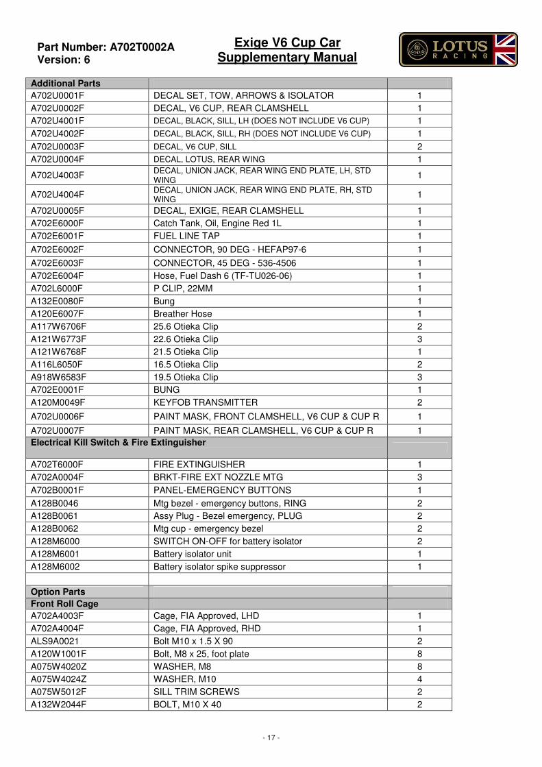
Additional Parts
A702U0001F DECAL SET, TOW, ARROWS & ISOLATOR 1
A702U0002F DECAL, V6 CUP, REAR CLAMSHELL 1
A702U4001F DECAL, BLACK, SILL, LH (DOES NOT INCLUDE V6 CUP) 1
A702U4002F DECAL, BLACK, SILL, RH (DOES NOT INCLUDE V6 CUP) 1
A702U0003F DECAL, V6 CUP, SILL 2
A702U0004F DECAL, LOTUS, REAR WING 1
A702U4003F DECAL, UNION JACK, REAR WING END PLATE, LH, STD WING
1
A702U4004F DECAL, UNION JACK, REAR WING END PLATE, RH, STD WING
1
A702U0005F DECAL, EXIGE, REAR CLAMSHELL 1
A702E6000F Catch Tank, Oil, Engine Red 1L 1
A702E6001F FUEL LINE TAP 1
A702E6002F CONNECTOR, 90 DEG - HEFAP97-6 1
A702E6003F CONNECTOR, 45 DEG - 536-4506 1
A702E6004F Hose, Fuel Dash 6 (TF-TU026-06) 1
A702L6000F P CLIP, 22MM 1
A132E0080F Bung 1
A120E6007F Breather Hose 1
A117W6706F 25.6 Otieka Clip 2
A121W6773F 22.6 Otieka Clip 3
A121W6768F 21.5 Otieka Clip 1
A116L6050F 16.5 Otieka Clip 2
A918W6583F 19.5 Otieka Clip 3
A702E0001F BUNG 1
A120M0049F KEYFOB TRANSMITTER 2
A702U0006F PAINT MASK, FRONT CLAMSHELL, V6 CUP & CUP R 1
A702U0007F PAINT MASK, REAR CLAMSHELL, V6 CUP & CUP R 1
Electrical Kill Switch & Fire Extinguisher
A702T6000F FIRE EXTINGUISHER 1
A702A0004F BRKT-FIRE EXT NOZZLE MTG 3
A702B0001F PANEL-EMERGENCY BUTTONS 1
A128B0046 Mtg bezel - emergency buttons, RING 2
A128B0061 Assy Plug - Bezel emergency, PLUG 2
A128B0062 Mtg cup - emergency bezel 2
A128M6000 SWITCH ON-OFF for battery isolator 2
A128M6001 Battery isolator unit 1
A128M6002 Battery isolator spike suppressor 1
Option Parts
Front Roll Cage
A702A4003F Cage, FIA Approved, LHD 1
A702A4004F Cage, FIA Approved, RHD 1
ALS9A0021 Bolt M10 x 1.5 X 90 2
A120W1001F Bolt, M8 x 25, foot plate 8
A075W4020Z WASHER, M8 8
A075W4024Z WASHER, M10 4
A075W5012F SILL TRIM SCREWS 2
A132W2044F BOLT, M10 X 40 2
Part Number: A702T0002A
Version: 6
Exige V6 Cup Car Supplementary Manual
- 18 -
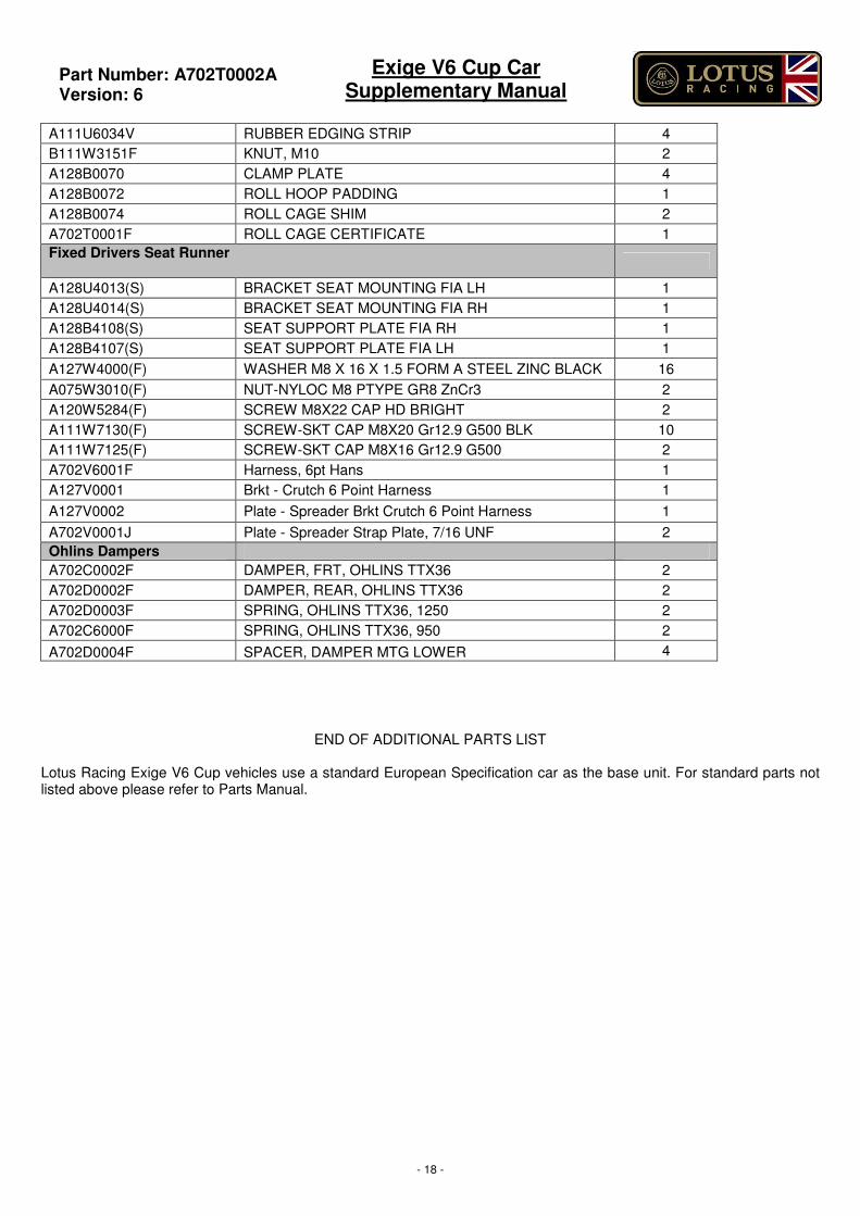
A111U6034V RUBBER EDGING STRIP 4
B111W3151F KNUT, M10 2
A128B0070 CLAMP PLATE 4
A128B0072 ROLL HOOP PADDING 1
A128B0074 ROLL CAGE SHIM 2
A702T0001F ROLL CAGE CERTIFICATE 1
Fixed Drivers Seat Runner
A128U4013(S) BRACKET SEAT MOUNTING FIA LH 1
A128U4014(S) BRACKET SEAT MOUNTING FIA RH 1
A128B4108(S) SEAT SUPPORT PLATE FIA RH 1
A128B4107(S) SEAT SUPPORT PLATE FIA LH 1
A127W4000(F) WASHER M8 X 16 X 1.5 FORM A STEEL ZINC BLACK 16
A075W3010(F) NUT-NYLOC M8 PTYPE GR8 ZnCr3 2
A120W5284(F) SCREW M8X22 CAP HD BRIGHT 2
A111W7130(F) SCREW-SKT CAP M8X20 Gr12.9 G500 BLK 10
A111W7125(F) SCREW-SKT CAP M8X16 Gr12.9 G500 2
A702V6001F Harness, 6pt Hans 1
A127V0001 Brkt - Crutch 6 Point Harness 1
A127V0002 Plate - Spreader Brkt Crutch 6 Point Harness 1
A702V0001J Plate - Spreader Strap Plate, 7/16 UNF 2
Ohlins Dampers
A702C0002F DAMPER, FRT, OHLINS TTX36 2
A702D0002F DAMPER, REAR, OHLINS TTX36 2
A702D0003F SPRING, OHLINS TTX36, 1250 2
A702C6000F SPRING, OHLINS TTX36, 950 2
A702D0004F SPACER, DAMPER MTG LOWER 4
END OF ADDITIONAL PARTS LIST
Lotus Racing Exige V6 Cup vehicles use a standard European Specification car as the base unit. For standard parts not listed above please refer to Parts Manual.
Part Number: A702T0002A
Version: 6
Exige V6 Cup Car Supplementary Manual
- 19 -
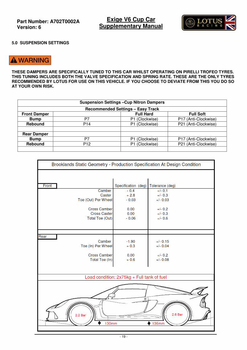
5.0 SUSPENSION SETTINGS
THESE DAMPERS ARE SPECIFICALLY TUNED TO THIS CAR WHILST OPERATING ON PIRELLI TROFEO TYRES. THIS TUNING INCLUDES BOTH THE VALVE SPECIFICATION AND SPRING RATE. THESE ARE THE ONLY TYRES RECOMMENDED BY LOTUS FOR USE ON THIS VEHICLE. IF YOU CHOOSE TO DEVIATE FROM THIS YOU DO SO AT YOUR OWN RISK.
Suspension Settings –Cup Nitron Dampers
Recommended Settings – Easy Track
Front Damper Full Hard Full Soft
Bump P7 P1 (Clockwise) P17 (Anti-Clockwise) Rebound P14 P1 (Clockwise) P21 (Anti-Clockwise)
Rear Damper
Bump P7 P1 (Clockwise) P17 (Anti-Clockwise) Rebound P12 P1 (Clockwise) P21 (Anti-Clockwise)
Part Number: A702T0002A
Version: 6
Exige V6 Cup Car Supplementary Manual
- 20 -
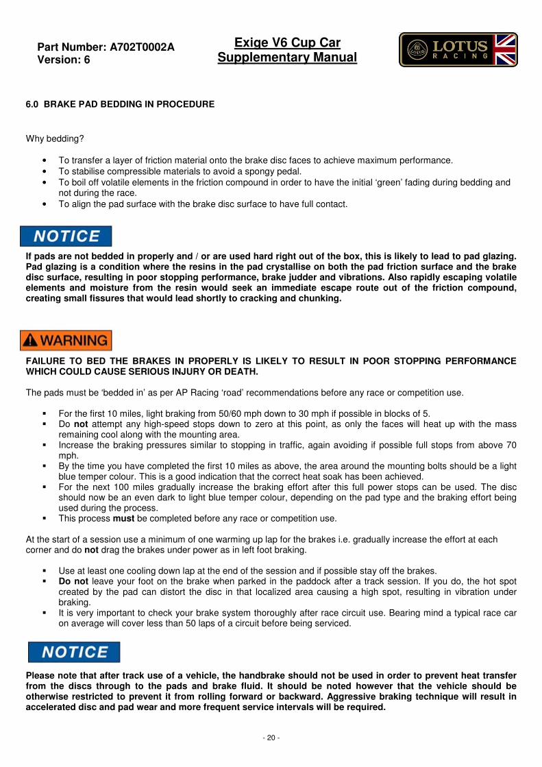
6.0 BRAKE PAD BEDDING IN PROCEDURE
Why bedding?
• To transfer a layer of friction material onto the brake disc faces to achieve maximum performance.
• To stabilise compressible materials to avoid a spongy pedal.
• To boil off volatile elements in the friction compound in order to have the initial ‘green’ fading during bedding and not during the race.
• To align the pad surface with the brake disc surface to have full contact.
If pads are not bedded in properly and / or are used hard right out of the box, this is likely to lead to pad glazing. Pad glazing is a condition where the resins in the pad crystallise on both the pad friction surface and the brake disc surface, resulting in poor stopping performance, brake judder and vibrations. Also rapidly escaping volatile elements and moisture from the resin would seek an immediate escape route out of the friction compound, creating small fissures that would lead shortly to cracking and chunking.
FAILURE TO BED THE BRAKES IN PROPERLY IS LIKELY TO RESULT IN POOR STOPPING PERFORMANCE WHICH COULD CAUSE SERIOUS INJURY OR DEATH. The pads must be ‘bedded in’ as per AP Racing ‘road’ recommendations before any race or competition use.
� For the first 10 miles, light braking from 50/60 mph down to 30 mph if possible in blocks of 5. � Do not attempt any high-speed stops down to zero at this point, as only the faces will heat up with the mass
remaining cool along with the mounting area. � Increase the braking pressures similar to stopping in traffic, again avoiding if possible full stops from above 70
mph. � By the time you have completed the first 10 miles as above, the area around the mounting bolts should be a light
blue temper colour. This is a good indication that the correct heat soak has been achieved. � For the next 100 miles gradually increase the braking effort after this full power stops can be used. The disc
should now be an even dark to light blue temper colour, depending on the pad type and the braking effort being used during the process.
� This process must be completed before any race or competition use. At the start of a session use a minimum of one warming up lap for the brakes i.e. gradually increase the effort at each corner and do not drag the brakes under power as in left foot braking.
� Use at least one cooling down lap at the end of the session and if possible stay off the brakes. � Do not leave your foot on the brake when parked in the paddock after a track session. If you do, the hot spot
created by the pad can distort the disc in that localized area causing a high spot, resulting in vibration under braking.
� It is very important to check your brake system thoroughly after race circuit use. Bearing mind a typical race car on average will cover less than 50 laps of a circuit before being serviced.
Please note that after track use of a vehicle, the handbrake should not be used in order to prevent heat transfer from the discs through to the pads and brake fluid. It should be noted however that the vehicle should be otherwise restricted to prevent it from rolling forward or backward. Aggressive braking technique will result in accelerated disc and pad wear and more frequent service intervals will be required.
Part Number: A702T0002A
Version: 6
Exige V6 Cup Car Supplementary Manual
- 21 -
7.0 VEHICLE RUNNING IN
For all running in details please refer to the owner’s handbook.
Part Number: A702T0002A
Version: 6
Exige V6 Cup Car Supplementary Manual
- 22 -
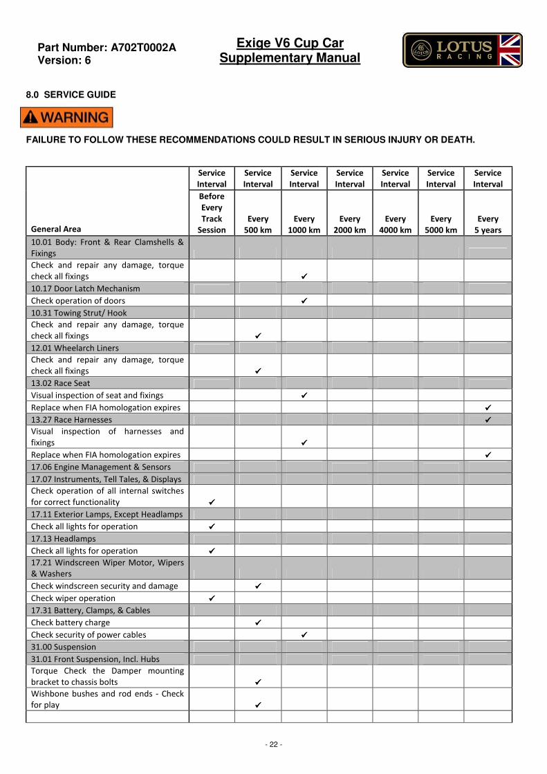
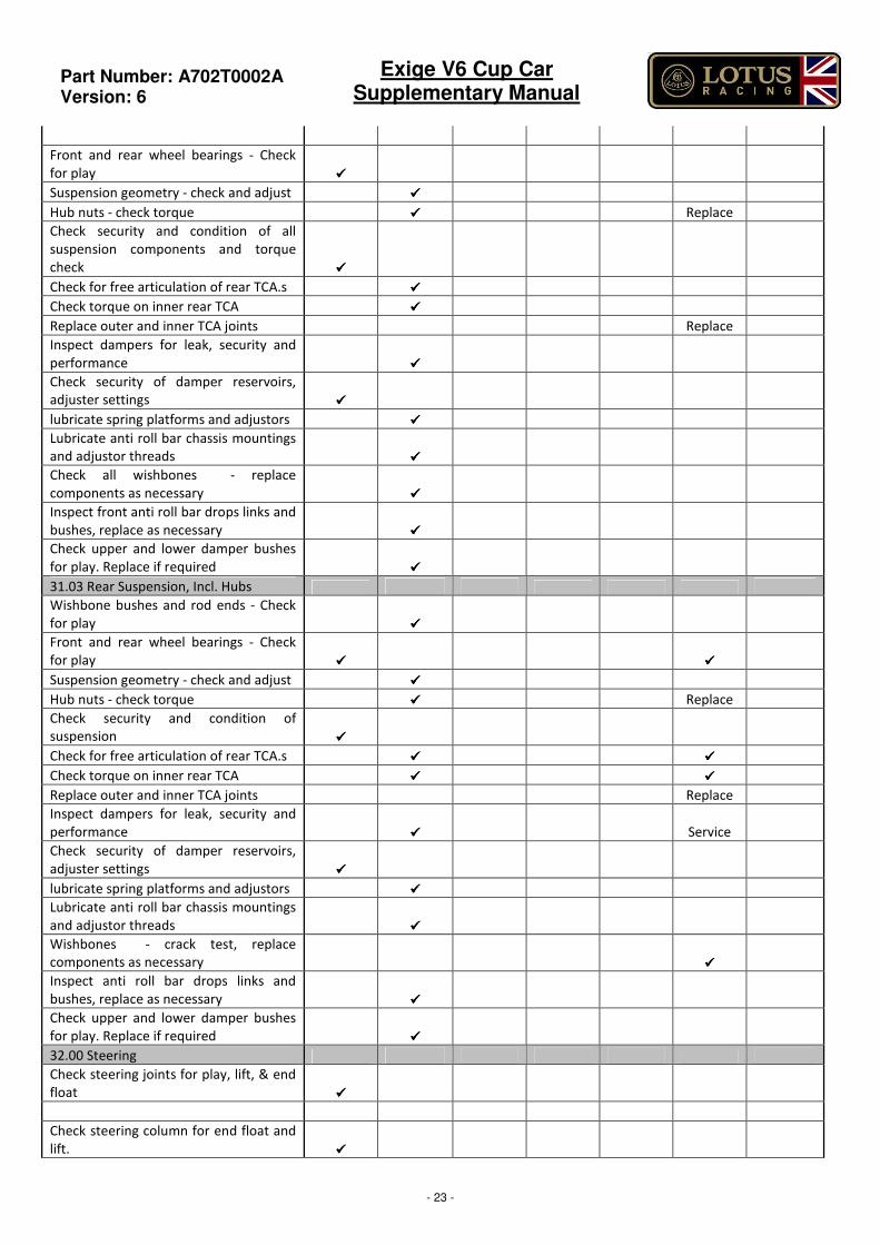
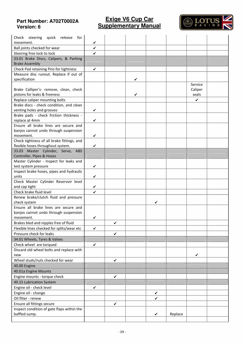
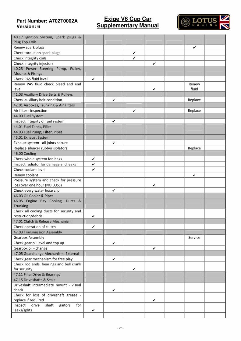
8.0 SERVICE GUIDE
FAILURE TO FOLLOW THESE RECOMMENDATIONS COULD RESULT IN SERIOUS INJURY OR DEATH.
Service
Interval
Service
Interval
Service
Interval
Service
Interval
Service
Interval
Service
Interval
Service
Interval
General Area
Before
Every
Track
Session
Every
500 km
Every
1000 km
Every
2000 km
Every
4000 km
Every
5000 km
Every
5 years
10.01 Body: Front & Rear Clamshells &
Fixings
Check and repair any damage, torque
check all fixings ����
10.17 Door Latch Mechanism
Check operation of doors ����
10.31 Towing Strut/ Hook
Check and repair any damage, torque
check all fixings ����
12.01 Wheelarch Liners
Check and repair any damage, torque
check all fixings ����
13.02 Race Seat
Visual inspection of seat and fixings ����
Replace when FIA homologation expires ����
13.27 Race Harnesses ����
Visual inspection of harnesses and
fixings ����
Replace when FIA homologation expires ����
17.06 Engine Management & Sensors
17.07 Instruments, Tell Tales, & Displays
Check operation of all internal switches
for correct functionality ����
17.11 Exterior Lamps, Except Headlamps
Check all lights for operation ����
17.13 Headlamps
Check all lights for operation ����
17.21 Windscreen Wiper Motor, Wipers
& Washers
Check windscreen security and damage ����
Check wiper operation ����
17.31 Battery, Clamps, & Cables
Check battery charge ����
Check security of power cables ����
31.00 Suspension
31.01 Front Suspension, Incl. Hubs
Torque Check the Damper mounting
bracket to chassis bolts ����
Wishbone bushes and rod ends - Check
for play ����
Part Number: A702T0002A
Version: 6
Exige V6 Cup Car Supplementary Manual
- 23 -
Front and rear wheel bearings - Check
for play ����
Suspension geometry - check and adjust ����
Hub nuts - check torque ���� Replace
Check security and condition of all
suspension components and torque
check ����
Check for free articulation of rear TCA.s ����
Check torque on inner rear TCA ����
Replace outer and inner TCA joints Replace
Inspect dampers for leak, security and
performance ����
Check security of damper reservoirs,
adjuster settings ����
lubricate spring platforms and adjustors ����
Lubricate anti roll bar chassis mountings
and adjustor threads ����
Check all wishbones - replace
components as necessary ����
Inspect front anti roll bar drops links and
bushes, replace as necessary ����
Check upper and lower damper bushes
for play. Replace if required ����
31.03 Rear Suspension, Incl. Hubs
Wishbone bushes and rod ends - Check
for play ����
Front and rear wheel bearings - Check
for play ���� ����
Suspension geometry - check and adjust ����
Hub nuts - check torque ���� Replace
Check security and condition of
suspension ����
Check for free articulation of rear TCA.s ���� ����
Check torque on inner rear TCA ���� ����
Replace outer and inner TCA joints Replace
Inspect dampers for leak, security and
performance ���� Service
Check security of damper reservoirs,
adjuster settings ����
lubricate spring platforms and adjustors ����
Lubricate anti roll bar chassis mountings
and adjustor threads ����
Wishbones - crack test, replace
components as necessary ����
Inspect anti roll bar drops links and
bushes, replace as necessary ����
Check upper and lower damper bushes
for play. Replace if required ����
32.00 Steering
Check steering joints for play, lift, & end
float ����
Check steering column for end float and
lift. ����
Part Number: A702T0002A
Version: 6
Exige V6 Cup Car Supplementary Manual
- 24 -
Check steering quick release for
movement. ����
Ball joints checked for wear ����
Steering free lock to lock ����
33.01 Brake Discs, Calipers, & Parking
Brake Assembly
Check Pad retaining Pins for tightness ����
Measure disc runout. Replace if out of
specification ����
Brake Calliper’s- remove, clean, check
pistons for leaks & freeness ����
Service
Caliper
seals
Replace caliper mounting bolts ����
Brake discs - check condition, and clean
venting holes and grooves ����
Brake pads - check friction thickness -
replace at 4mm ����
Ensure all brake lines are secure and
banjos cannot undo through suspension
movement. ����
Check tightness of all brake fittings, and
flexible hoses throughout system. ����
33.03 Master Cylinder, Servo, ABS
Controller, Pipes & Hoses
Master Cylinder - Inspect for leaks and
test system pressure ����
Inspect brake hoses, pipes and hydraulic
units ����
Check Master Cylinder Reservoir level
and cap tight ����
Check brake fluid level ����
Renew brake/clutch fluid and pressure
check system ����
Ensure all brake lines are secure and
banjos cannot undo through suspension
movement. ����
Brakes bled and nipples free of fluid ����
Flexible lines checked for splits/wear etc ����
Pressure check for leaks ����
34.01 Wheels, Tyres & Valves
Check wheel are torqued ����
Discard old wheel bolts and replace with
new ����
Wheel studs/nuts checked for wear ����
40.00 Engine
40.01a Engine Mounts
Engine mounts - torque check ����
40.15 Lubrication System
Engine oil - check level ����
Engine oil - change ����
Oil filter - renew ����
Ensure all fittings secure ����
Inspect condition of gate flaps within the
baffled sump. ���� Replace
Part Number: A702T0002A
Version: 6
Exige V6 Cup Car Supplementary Manual
- 25 -
40.17 Ignition System, Spark plugs &
Plug Top Coils
Renew spark plugs ����
Check torque on spark plugs ����
Check integrity coils ����
Check integrity injectors ����
40.25 Power Steering Pump, Pulley,
Mounts & Fixings
Check PAS fluid level ����
Renew PAS fluid check bleed and end
level ����
Renew
fluid
41.03 Auxiliary Drive Belts & Pulleys
Check auxiliary belt condition ���� Replace
42.01 Airboxes, Trunking & Air Filters
Air filter - inspection ���� Replace
44.00 Fuel System
Inspect integrity of fuel system ����
44.01 Fuel Tanks, Filler
44.03 Fuel Pump; Filter, Pipes
45.01 Exhaust System
Exhaust system - all joints secure ����
Replace silencer rubber isolators Replace
46.00 Cooling
Check whole system for leaks ����
Inspect radiator for damage and leaks ����
Check coolant level ����
Renew coolant ����
Pressure system and check for pressure
loss over one hour (NO LOSS) ����
Check every water hose clip ����
46.03 Oil Cooler & Pipes
46.05 Engine Bay Cooling, Ducts &
Trunking
Check all cooling ducts for security and
restriction/debris ����
47.01 Clutch & Release Mechanism
Check operation of clutch ����
47.03 Transmission Assembly
Gearbox Assembly Service
Check gear oil level and top up ����
Gearbox oil - change ����
47.05 Gearchange Mechanism, External
Check gear mechanism for free play ����
Check rod ends, bearings and bell crank
for security ����
47.11 Final Drive & Bearings
47.15 Driveshafts & Seals
Driveshaft intermediate mount - visual
check ����
Check for loss of driveshaft grease -
replace if required ����
Inspect drive shaft gaitors for
leaks/splits ����
Part Number: A702T0002A
Version: 6
Exige V6 Cup Car Supplementary Manual
- 26 -
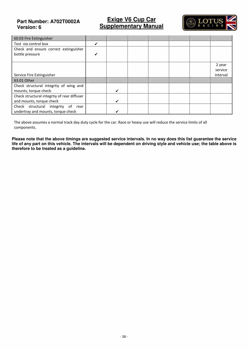
60.03 Fire Extinguisher
Test via control box ����
Check and ensure correct extinguisher
bottle pressure ����
Service Fire Extinguisher
2 year
service
interval
63.01 Other
Check structural integrtiy of wing and
mounts, torque check ����
Check structural integrtiy of rear diffuser
and mounts, torque check ����
Check structural integrtiy of rear
undertray and mounts, torque check ����
The above assumes a normal track day duty cycle for the car. Race or heavy use will reduce the service limits of all
components.
Please note that the above timings are suggested service intervals. In no way does this list guarantee the service life of any part on this vehicle. The intervals will be dependent on driving style and vehicle use; the table above is therefore to be treated as a guideline.
Part Number: A702T0002A
Version: 6
Exige V6 Cup Car Supplementary Manual
- 27 -
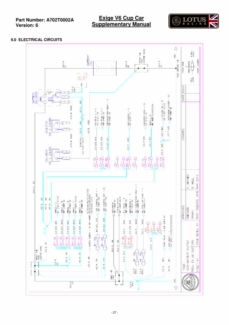
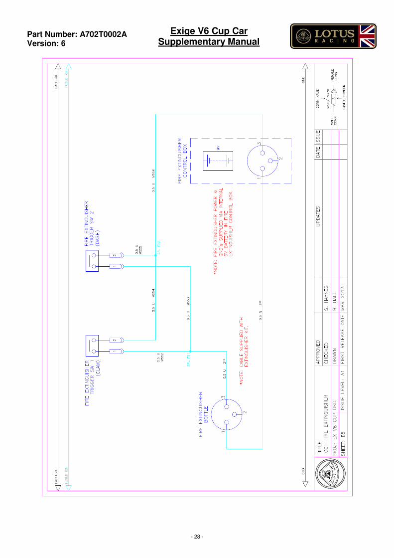
9.0 ELECTRICAL CIRCUITS
Part Number: A702T0002A
Version: 6
Exige V6 Cup Car Supplementary Manual
- 28 -