Embed Size (px)
Citation preview

Lost and Found: Mathematically Locating Ocean
Downed Aircraft
Control #38724
February 9, 2015
Abstract
Given the vast size of the Earth's oceans, and the dynamics of theircurrents, any attempt to give the exact location of a downed aircraft isinfinitely daunting. Instead of attempting the exact, what we proposein this paper is an approach to the problem that maximizes search ef-ficiency. Our approach will be developed over several steps: 1) developthe disappearance interval and search radius, 2) model the trajec-tory of the aircraft while still in the air using scenario and probabil-ity analysis, 3) model the effects of the ocean's currents on thefuselage at the crash site, and 4) apply Bayesian search methods tomaximize search efficiency. Using the aircraft's velocity, trajectory,and location at time of last contact, we apply a modified version of theequations of motion to determine the possible crash points within abounded region. Working within this region, we apply different prob-ability distributions to the aircraft's location under varying scenariossuch as mechanical failure or bad weather conditions. We then analyzethe effects of ocean currents on the fuselage to determine a maximumdrift. Accordingly, our model will give us a series of estimates of theaircraft's resting location on the seafloor. Each of these resting loca-tions will be defined in a search area and assigned a probability so thatBayesian search theory can be applied. Finally, we will address how totest our model for accuracy and how our model might be improved byavailable technology, such as advanced satellite tracking.
1

2 of 21 Control #38724
Contents
1 Introduction 31.1 Outline of Our Approach . . . . . . . . . . . . . . . . . 31.2 Assumptions . . . . . . . . . . . . . . . . . . . . . . . . 41.3 Definition of Terms . . . . . . . . . . . . . . . . . . . . . 5
2 Probability Density of Mayday Indicators 52.1 Storm Scenario . . . . . . . . . . . . . . . . . . . . . . . 52.2 Mechanical Failure Scenario . . . . . . . . . . . . . . . . 6
3 Modeling Crash Sites 73.1 Known Values . . . . . . . . . . . . . . . . . . . . . . . . 73.2 Trajectory of Aircraft From Mayday Indicator . . . . . . 73.3 Determining Aircraft Crash Points . . . . . . . . . . . . 8
4 Modeling Aircraft Resting Location 94.1 Important Values . . . . . . . . . . . . . . . . . . . . . . 9
4.1.1 Weight of Fuselage . . . . . . . . . . . . . . . . . 94.1.2 Inertia of Fuselage . . . . . . . . . . . . . . . . . 104.1.3 Drag Force . . . . . . . . . . . . . . . . . . . . . 10
4.2 Possible Complications . . . . . . . . . . . . . . . . . . . 104.2.1 Ocean Currents . . . . . . . . . . . . . . . . . . . 104.2.2 Wind . . . . . . . . . . . . . . . . . . . . . . . . 114.2.3 Waves . . . . . . . . . . . . . . . . . . . . . . . . 12
4.3 Forecasting the Sinking Pattern . . . . . . . . . . . . . . 124.3.1 Sinking Upon Impact . . . . . . . . . . . . . . . 124.3.2 Drifting Before Sinking . . . . . . . . . . . . . . 13
5 Locating Aircraft in Search Areas 145.1 Application of Bayesian Search Theory . . . . . . . . . . 145.2 Recommended Search Vehicles . . . . . . . . . . . . . . 15
5.2.1 If Survivors are Found . . . . . . . . . . . . . . . 155.2.2 If No Survivors are Found . . . . . . . . . . . . . 15
6 Testing the Model 15
7 Improving the Model 167.1 Recursive Tracking . . . . . . . . . . . . . . . . . . . . . 167.2 Application of Global Tracking Systems . . . . . . . . . 17
8 Conclusion 17
9 Executive Summary 19
References 21
2

3 of 21 Control #38724
1 Introduction
Given recent events concerning ocean downed aircraft, we understandthat efficient methods and models are needed to aid search and rescueefforts. The sheer size of the Earth's oceans render any search andrescue efforts formidable and so we will utilize well-developed mathe-matical principles to aid in these efforts.
In this paper we present a model for locating aircraft lost at seaand presumed to be downed. Our model takes into account criticalfactors such as location, trajectory, and velocity at point of last contact.Additional factors considered in the model are aircraft mass as well asprevailing weather and ocean currents. This information is used inour model to determine the most likely crash and resting sites of theaircraft. The model maximizes search efficiency by minimizing thetime it takes to locate the aircraft.
1.1 Outline of Our Approach
The beginning of our paper will focus on developing the necessaryframework for the model to work. Here we consider the reasons whichmay have caused the aircraft to go down. Reasons due to mechanicalfailure or severe weather have different implications on pilot reaction.Additionally, we consider the possible scenarios once the aircraft hitsthe ocean; it may sink or may drift for an undetermined amount oftime before sinking. These scenarios are all considered throughout thedevelopment of the model. Our priorities are as follows:
� Develop the model: Search EfficiencyThroughout the development of our model, we use a modifiedversions of the equations of motion, probability distribution fit-ting, and Bayesian search methods. The motivating idea is tocreate efficient search techniques while working against a clock.We identify the most probable crash sites and a maximum searchradius.
� Probability Density FittingDifferent distress scenarios imply different pilot reactions. Weidentify the most probable causes of an aircraft crash to be: ex-treme weather conditions or mechanical/human failure. Underthis scenario analysis, we fit a probability density function cen-tered on the most probable crash sites which are considered tobe random variables.
� Bayesian Search MethodGiven a bounded search region, we establish disjoint subregionseach with an assigned probability of containing the fuselage. Withinthe sub regions, another probability of locating the plane is es-
3
4 of 21 Control #38724
tablished and is based on factors such as water depth, searchequipment, and technology. Using Bayesian statistics, the re-sults are a decreased probability in areas searched and increasedprobability in the other subregions. This may seem like commonsense, but having an organized and systematic search methodbased on probability theory will aid any ocean search and rescueeffort. Bayesian search methods were successfully employed inthe location of Air France Flight 447 [2].
� Analysis of Results: Suggestions for Improvement andImplementationTesting the model against unavailable real data proved difficult.What we are confident in is the approach to the problem and themodeling that we propose on maximizing the search efficiency.We offer suggestions for further improvement and implementa-tion of the model through simulation in ocean search and rescueefforts.
1.2 Assumptions
Due to the complicated nature of locating missing aircraft, we willintroduce a few assumptions to our model.
� Any aircraft must communicate with air traffic control (ATC)every thirty minutes. With current technologies, communicationbetween aircraft and ATC is more frequent for many aircraft andthirty minute intervals is standard for other aircraft followingprotocol. The thirty minute limit assumption gives a definite timeframe to work within which the aircraft disappeared. Our modelcan be applied similarly in situations where radar contact is lostbut the aircraft continues to send basic information (velocity,altitude, latitude and longitude) to satellite receivers (as manymodern aircraft do).
� The aircraft has crashed due to outside forces (weather) or amechanical error of some kind. Our model was not designed toanalyze a hijacking or intentional crash off-course.
� When confronted with a storm, a pilot will fly above or throughthe storm. They will not attempt to fly around the storm unlessgiven authorized permission from ATC. This is in line with pro-tocol; a pilot will not alter course unless he is authorized to doso by ATC.
� The aircraft is not sending out any signals or information regard-ing its location. If this were the case, our model would not benecessary to locate the airplane.
� The aircraft will sustain damage upon crashing. Specifically, wewill assume the fuselage has separated from the wings of the
4

5 of 21 Control #38724
aircraft. An aircraft is highly unlikely to undergo a major crashand lose communication abilities if it has not sustained majordamage in some way.
1.3 Definition of Terms
� Disappearance Interval: Time in between last point of con-tact and scheduled point of contact. If scheduled contact is notmade, then the disappearance interval is the maximum of thetime elapsed between points of contact. Our assumption is thatthe disappearance interval is thirty minutes.
� Search Efficiency: Governing search principle; constant updateof high probability search areas through Bayesian analysis.
� Mayday Indicator: The location that the aircraft begins tolose control in the sky.
� Crash Point: The location that the aircraft makes contact withthe water.
� Resting Location: The final location of the aircraft once itreaches the ocean floor.
2 Probability Density of Mayday Indica-tors
In order to apply the Bayesian search method, we first develop a prob-ability density function (PDF) that will aid in prioritizing search areaswithin the established radius. We consider the two scenarios that mo-tivate our model development whose characteristics prescribe distinctPDFs.
2.1 Storm Scenario
Given our assumption that a pilot will fly above or into the middle ofa storm, we consider the probable location of the craft as it is beingtaken down by the storm. In this sense, the mayday indicators are bestmodeled by a positively skewed log normal density function [10]:
f(x) =1√2πσ
x exp
(− [ln(x)− µ]2
2σ2
)(1)
with the mean, mode, variance and skewness defined:
Mean: eµ+σ2/2 (2)
Mode: eµ−σ2
(3)
5
6 of 21 Control #38724
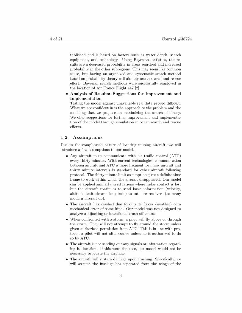
Figure 1: A sample PDF in a storm scenario with the aircraft representedby the black arrow. The red area highlights the highest probability locationsfor mayday indicators and thus the highest density of mayday indicators
Variance: (eσ2
− 1)e2µ+σ2
(4)
Skewness: (eσ2
+ 2)√eσ2 − 1 (5)
where µ is the location parameter.We will define the mode of our PDF to be the center of the storm.
We have chosen this designation as it is unlikely the aircraft will im-mediately fall out of the sky once entering the storm (even thoughit is possible) but will instead fly some undetermined distance beforecrashing.
2.2 Mechanical Failure Scenario
The event of mechanical failure over the ocean expands the probablesearch area. Under this scenario the location of the aircraft is bestmodeled by a normal distribution with a higher probability of coastingbefore hitting the water. The density function will have a negativekurtosis to reflect this probability. The normal density function isgiven by
f(x) =1
2√π
exp
(−(x− µ)2
σ2
)(6)
with a typical mean (µ), a mode of µ, typical variance (σ2) and noskew.
It is important to note that the normal distribution, due to itsnegative kurtosis, will have a larger standard deviation and a higherprobability of mayday indicators in extreme ranges when compared to
6

7 of 21 Control #38724
our log normal distribution. Thus the mayday indicator “hot spot”will be larger for a mechanical failure scenario and our search area willbe expanded.
3 Modeling Crash Sites
3.1 Known Values
There is a thirty minute window between communications with pilotsand ATC in which the aircraft can disappear (the disappearance inter-val). At each “check in” with ATC, a pilot must report their location,altitude, velocity, and intended path. Thus, from the last point ofcontact, we are aware of the aircraft's altitude and velocity. We canassume in the following thirty minutes that these will be held nearconstant as needless changes in velocity waste fuel.
3.2 Trajectory of Aircraft From Mayday Indicator
We will use the following equations of motion and their modificationsas outlined by Wilson [12] to represent aerodynamic objects falling toEarth at an initial horizontal velocity.
du
dt= −guV
U2,
dv
dt= g
(1− vV
U2
)(7)
andV 2
r= g
u
V,
dV
dt= g
(v
V− V 2
U2
)(8)
Where U = terminal velocity, g = 9.8m/s2, u = horizontal componentof velocity and v = vertical component of velocity.
Through manipulation and various substitutions we can conclude
d2y
dx2=
g
u20
e2gs/U2
(9)
for an arc s. To approximate this curve we can enclose it between twoother curves, x < s < x+ y. Thus we can model the trajectory as
d2y
dx2=
g
u20
e2gx/U2
, lies above the actual trajectory (10)
d2y
dx2=
g
u20
e2gy/U2
, lies above the actual trajectory (11)
d2y
dx2=
g
u20
e2g(x+y)/U2
, lies below the actual trajectory (12)
7

8 of 21 Control #38724
It is simple to integrate (10) and (11), the solutions are
y =U4
4gu20
(e2gx/U2
− 1)− U2x
2u20
(13)
and
y =U2
glog sec
gx
u0U(14)
Each of these will provide upper bounds to the actual trajectory, with(13) being most accurate for short trajectories and (14) being mostapplicable in the case that initial altitude is large.
We can solve (12) given the substitution of
z = x+ ydz
dx=dy
dx+ 1,
d2z
dx2=d2y
dx2(15)
and so the solution of (12), and the lower bound to our trajectory, is
y + x =U3
g
[log sec
(gx
u0U
√1− u2
0
U2+ sin−1 u0
U
)+ log
√1− u2
0
U2
](16)
Depending upon the altitude of the flight, either (13) or (14) could beaveraged with (15) to determine a probable crash point.
3.3 Determining Aircraft Crash Points
At cruising speed, the average long-distance commercial airplane fliesat up to 900km/h. In our disappearance interval, this leaves 450kmas a maximum distance that the plane could have traveled. It is notfeasible to search this entire area or to test the probability at eachmayday indicator that the aircraft crashed.
Instead, we will test for ten probable mayday indicators based offof the PDF. Within one standard deviation of the mean of our PDFwe will place seven probable mayday indicators (seventy percent ofmayday indicators), within two deviations we will place nine maydayindicators (ninety percent) and within three deviations we will placeten mayday indicators (one hundred percent). This approximatelyparallels the 68 − 95 − 99.7 rule associated to normal distributions.Mayday indicators will be placed such that the interval of the devi-ation(s) is spanned but areas of highest probabilities will receive thehighest density of mayday indicators, see Figure 2.
We will then take each of these mayday indicators and apply ourmodified trajectory equations to determine the crash point. The prob-ability assigned to each mayday indicator that the aircraft lost controlat this point is now transfered to the crash site as the probability thatthe aircraft made contact with the ocean at this point.
8

9 of 21 Control #38724
Figure 2: An example of how mayday indicators (red dots) might be assignedin a storm scenario
4 Modeling Aircraft Resting Location
After the aircraft has crashed and broken apart on impact, the fuselageand other debris will begin to move with the currents, wind and/orwaves as they sink. We will once again employ modified forms of ourtrajectory equations from Section 3.2 to model the path of the fuselageas it sinks. It is important to note that the horizontal componentof velocity is now dependent upon the outside factors such as oceancurrents.
4.1 Important Values
To determine how the aircraft might be moved once it is in the ocean,we need to know some basic values.
4.1.1 Weight of Fuselage
The fuselage will immediately begin to lose pressurization after thecrash as pressurized air is no longer being pumped into the cabin.Thus the weight of the fuselage [1],
Wfuse = (1.051 + .102xIfuse)Vfuse (17)
will be determined by Ifuse =I2p+I2b
2Iband its volume, Vfuse, where
Ip = pressure index and Ib = bending index.
9

10 of 21 Control #38724
4.1.2 Inertia of Fuselage
The tendency for the fuselage not to move will be given by it’s inertia[5]
J =
(n∑i=1
mix2i − xsck
n∑i=1
)(18)
where
xsck =
∑ni=1mixi∑ni=1mi
= center of gravity (19)
The fuselage will not be moved in any direction unless the inertiais first overcome.
4.1.3 Drag Force
The drag force will be an important component in determining howthe aircraft moves in the water. Drag force is given by
Fd = cd(1/2)ρv2A (20)
where Fd = drag force in Newtons, cd is the drag coefficient equal to0.045 [9], ρ = density of fluid, v = flow velocity and A is the charac-teristic frontal area of the body. It is important to note that our dragforce will be a function of the density of the water which depends uponwater temperature and salinity. Ocean water density can be averagedto 1027kg/m3 at sea surface but the exact value should be calculatedfor the body of water the aircraft crashed into.
4.2 Possible Complications
4.2.1 Ocean Currents
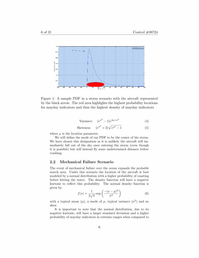
Surface currents pose an interesting obstacle in the search of aircraftlost at sea. Once the aircraft has crashed, it can be carried away inmany directions and at varying speeds, depending upon the currentspresent. Fortunately, currents are well documented and monitoredwith ample information on their strength and direction, as seen inFigure 3. To determine how far the fuselage is likely to travel on anygiven current, you simply need to know the velocity of the current, theweight of the fuselage and the drag in water (the latter two of which wehave just shown how to calculate and the former of which is availablefrom a variety of sources).
10
11 of 21 Control #38724
Figure 3: A visual representation of global ocean currents [8]
Figure 4: Global wind patterns [6]
4.2.2 Wind
The force of wind on the fuselage will be given by
F = APcd (21)
where A is the area of the object, P = 0.00256v2 is the wind pressure,cd is the drag coefficient and v is the velocity of the wind. If windwere to affect fuselage movement in water, this wind force would needto be greater than the inertia of the fuselage. Note however that thewind should have a minimal effect as the fuselage is aerodynamically
11

12 of 21 Control #38724
designed and will not be moved like a sail boat. As such we will dealspecifically with the currents when determining fuselage movement.
However, debris movement in water can be affected by wind pat-terns, this will play a large role in how to improve our model. It isimportant to understand that as wind is the driving force behind sur-face currents, the direction of the currents and wind are generally thesame, as can be seen in a quick comparison of Figures 3 and 4.
4.2.3 Waves
Waves, while seemingly important, are not a major role in the move-ment of objects at sea. When a wave encounters an object on thewater, it appears to move it forward. However, when the wave fallsback, it takes the object with it back to its original location [11]. Thiscan be seen when examining buoys floating in the waves. Due to this,the main role of waves in our model will be damaging the aircraft afterit has crashed into the water, leading to faster sinking of the fuselage.
4.3 Forecasting the Sinking Pattern
There are two scenarios to consider when the fuselage is sinking: onein which the aircraft begins to sink immediately upon impact due topreviously sustained damage and another in which the aircraft driftswith the currents before sinking. Note that in either scenario, thefuselage will sink as if in a “nose dive”. This is due to the fact that asthe fuselage fills with water, it will naturally tip in whichever directionis heavier and will sink in this manner. It is nearly impossible for thefuselage to be perfectly balanced when hitting the water and to stayin this equilibrium while filling with water and sinking, thus the casewill be ignored.
4.3.1 Sinking Upon Impact
Given Wilson’s modifications [12] of the equations of motion below wewant to analyze the effects of sinking in a “nose dive” position on anaerodynamic object's horizontal and vertical trajectory.
du
dt= −guV
U2,
dv
dt= g
(1− vV
U2
)(22)
andV 2
r= g
u
V,
dV
dt= g
(v
V− V 2
U2
)(23)
where once again U = terminal velocity, g = 9.8m/s2, u = horizontalcomponent of velocity, v = vertical component of velocity and r = ra-dius of curvature of the path.
12
13 of 21 Control #38724
Rewriting the second portion of (23),
VdV
dy= g
(1− V 2
U2
V
v
)(24)
we can analyze the relation between the tangential and vertical veloc-ities. It is easy to deduce that the increase in V with a vertical dropfrom y, will be less than the increase in v with the same vertical drop;the vertical velocity dominates the tangential velocity [12]. Hence, thedirection of a solid body in downward free-fall will be dominated bythe vertical velocity, minimizing the drag effects of the ocean current.
A further analysis considers the generalization to different mediumswith varying resistance. We start by considering the arc of drift withrespect to time. Noting that (22) may be integrated,
du
dt=du
ds
ds
dt= V
du
ds,
du
ds= − gu
U2, u = u0e
−gs/U2
(25)
reveals that horizontal velocity decreases exponentially with respect toarc distance traveled and that
1
r=
d2ydx2
[1 + ( dydx )2]3/2=
d2ydx2
V 3
u3
= g( u
V 3
)(26)
This calculation shows that
d2y
dx2=
g
u2(27)
holds for all mediums of varying resistance [12].Thus in this scenario, as the fuselage begins to sink immediately, it's
location can be approximated almost directly below the crash point.We will define our search area as a circle of radius 3 nautical miles(NM) around this point.
4.3.2 Drifting Before Sinking
If the fuselage is intact enough to not immediately begin sinking andthe force provided by the currents is strong enough to overcome theinertia, the fuselage will begin floating in the direction of the currents.However, a fuselage can only float for a certain amount of time. Air-craft are not built air- or watertight, instead they are sealed to keephigh pressure air inside the cabin with pressurized air being constantlypumped in. In the event of a crash, the cabin becomes de-pressurized.The seals are then forced to work to prevent higher pressure water fromentering, a task they were not designed to do and will ultimately failat. Even in a fuselage undamaged by the crash, water will immediatelybegin to enter the cabin, affecting the buoyancy of the fuselage.
13

14 of 21 Control #38724
Once the buoyant force is less than the force of gravity:
Fb = gρV < gm (28)
for ρ = water density, V = volume, g = gravity and m = mass, thefuselage will begin to sink. Knowing this, we have calculated thatit is highly unlikely that an object will drift more than one nauticalmile from its original crash site before beginning to sink. It is simplytoo improbable that the fuselage is in good enough condition after thecrash to maintain buoyancy longer than that. Thus the search radiusoutlined above will encompass any possibility of drifting and will workin either scenario.
Note we have ignored the possibility that a storm could be presentand altering the drifting path. While a powerful storm could carrythe fuselage farther than any currents might be able to in the sameamount of time, it will also damage the fuselage more dramatically.This will lead to a more rapid loss of buoyancy and, ultimately, thefuselage sinking even faster than if the storm were absent.
5 Locating Aircraft in Search Areas
5.1 Application of Bayesian Search Theory
To optimize our search for the missing aircraft we will apply Bayesiansearch methods based on our probabilities determined in the abovesections.
Let S be the set of all of our search areas, bounded and disjoint.We have assigned a probability, pi, of the aircraft being in any Siusing our probability density function. For each Si there exists anotherprobability, qi, of finding the aircraft. This qi is dependent upon manyfactors, such as the depth of the water and the effectiveness of thechosen search vehicle. Bayesian search theory states that if we checkany of our search areas and do not find the aircraft, the probability,p′i, of it being in Si is now
p′i =pi(1− qi)
(1− pi) + pi(1− qi)= pi
1− qi1− piqi
(29)
and the updated probability, p′k, of the aircraft being in some other Skis
p′k = pk1
1− piqi(30)
Note that 0 < p′i < pi < 1 and pk < p′k < 1. Hence the probability ofthe aircraft being where we have already searched decreases (but doesnot vanish) and the probability of the aircraft being where we haven’t
14

15 of 21 Control #38724
checked increases. Our probabilities will be constantly updated, givingus the highest chance of locating the aircraft in the minimal amountof time.
5.2 Recommended Search Vehicles
In any downed aircraft scenario, we recommend that unmanned aerialvehicles (UAV) are immediately deployed to scout for potential sur-vivor rafts and/or obvious debris. UAVs are fast and able to scourlarge areas quickly without risk of human injury. The next course ofaction we recommend depends upon if survivors are found or not.
5.2.1 If Survivors are Found
In the case that survivors are present, we recommend the tactic out-lined by Furukawa et al in their paper on Bayesian search for multipletargets [4]. In short, this paper tests the effectiveness of a combinedeffort between UAVs and helicopters with rescue workers. The UAVsfly ahead of the helicopters to locate the survivors and fly in circlesaround the survivors, lighting the area and alerting the helicopters totheir location. The helicopters and rescue workers can then begin col-lecting the survivors, bringing them back to a safe location. The papershows the combined efforts of UAVs and helicopter search and rescueteams to be quite effective in the location and rescue of survivors. Onceeach passenger has been found and brought to safety, we recommendthe search proceed as if no survivors are found.
5.2.2 If No Survivors are Found
In the case that no survivors are found, the main priority becomesthe location of the fuselage so that bodies of passengers and the blackbox can be collected. In this scenario, we recommend that underwatervehicles are deployed to search at least two areas of highest probability.This allows for the timely search of multiple areas without requiringthe simultaneous search of all areas, which could become costly andmay not be feasible for the search team. If the fuselage is found,searching is halted as bodies and important equipment are brought tosurface. Searching would continue with last calculated probabilities ifa passenger or some item of value is determined missing.
6 Testing the Model
Our model relies on specific information (wind speed, flight location,storm locations, etc) available at the time of the crash and within a lim-ited time frame after. As this data was not recorded, or at least is not
15

16 of 21 Control #38724
available to the public, for well documented cases (such as MalaysianAirlines Flight MH370 and Air France Flight 447) we unfortunatelycannot apply our model to them.
With this in mind we attempted to simulate an aircraft crash sothat our model could be tested. However, due to a lack of tools andadvanced technology at our disposal, our simulations were reduced totrivial problems that did not challenge our model. The simulationswere too predictable and did not accurately represent the variabilityin an actual aircraft crash. We could not in good faith claim that thesesimulations truly tested our model.
Having said this, we firmly believe in the approach our model em-ploys. We are confident that, given the right tools and technology, asimulation could be constructed that mirrors realistic circumstancesthat could then test our model for accuracy. In this scenario, we rec-ommend the following course of action:
� Construct a probability density function based on the chance ofmechanical error or storm interference as outlined in Section 2.
� Using this PDF, determine potential mayday indicators.
� From each of these determined crash locations, apply our modi-fied trajectory equations from Section 3.2 to determine the crashpoints.
� Define a search area around each of these points of radius 3NM .
We are confident that, when tested under realistic circumstances, ourmodel will prove to accurately predict resting location of the aircraft.
7 Improving the Model
No model will be able to accurately describe the exact location ofan aircraft’s crash in the ocean, there are too many moving variables.However, we have outlined a few ways in which our model could be im-proved and how technology could be improved for a better applicationof our model.
7.1 Recursive Tracking
Often, an aircraft crashes into the sea and, for one reason or another,cannot be located for a long period of time. Perhaps the most famouscases would be of Malaysian Airlines Flight MH370 and Air FranceFlight 447. While Flight MH370 is still missing, Flight 447 was foundtwo years after the crash by a team who developed and employed arecursive tracking method [2]. In short, the movement of bodies anddebris were traced backwards in time. This was done through the use
16
17 of 21 Control #38724
of a three-dimensional Lagrangian tracking program
Pn(x̄t−∆t, t−∆t) = −∫ t−∆t
t
(v̄ + αw̄)dt+ Pn(x̄t, t) (31)
where Pn(x̄t−∆t, t−∆t) and Pn(x̄t, t) are the locations of the nth objectat time t − ∆t and t, v̄ is the velocity vector, w̄ is the wind velocityvector and α is the wind drag factor.
The application of this technique to our model would help withcreating even more accurate representations of probabilities of crashsites, leading to the even faster location of the aircraft. This methodwould also allow our model to be used in cases it was not designed for,such as in a plane hijacking or intentional crash.
7.2 Application of Global Tracking Systems
It will come as no surprise that the accuracy of our model is dependentupon accurate tracking systems. Radar, while common, is no longerthe best method for tracking aircraft, especially over the ocean. In-stead, we recommend the application of improved tracking systems. Apromising system, the NextGen satellite system, tracks aircraft usingAutomatic Dependent Surveillance-Broadcast (ADS-B). The NextGensystem has already been employed by several aviation administrations,with the Federal Aviation Administration (FAA) deploying it nation-wide in 2013 [3]. The NextGen system was combined with other track-ing systems by Liu et al. in an attempt to improve aircraft trackingthrough data fusion. [7]. The multiple data sources and algorithms runcreated a highly accurate system with a low sensor fault. Applicationsof either of these two tracking systems, or another promising trackingsystem, would not only increase the accuracy of our model but reducethe probability of crash in the first place.
8 Conclusion
Locating an ocean downed aircraft to a precise point is unrealistic.Therefore, the task becomes one of maximizing search efficiency. Wepropose a model based on the assumption that pilots make contactwithin specified time intervals. Our model then calculates a maximumsearch area given data retrieved from the plane at point of last con-tact: velocity, trajectory, and weather conditions. We then use scenarioanalysis to model the distributions of the possible crash sites findingthat different scenarios would suggest different probability distribu-tions. Our model uses Bayesian search methods to maximize searchefficiency after having established the hypotheses and assigning a dis-tribution function to the search area. Lack of sufficient data has made
17

18 of 21 Control #38724
testing the model challenging and final results are inconclusive. How-ever, we would like to stress our confidence in the approach that themodel employs and emphasize our belief that further testing will revealpositive results.
18

19 of 21 Control #38724
9 Executive Summary
As is understood, the priority in any downed aircraft scenario is sal-vaging human life. Due to the nature of aircraft crashes, often thisis not a possibility and the next priority becomes locating the bod-ies of the passengers. With this in mind, after an aircraft is presumeddowned in the ocean, the most critical success factor is time. In view ofrecent cases of ocean downed aircraft, it is understood in our industrythat there is a dire need for more precise and efficient search methods.Our team has developed a method that maximizes the efficiency ofsearch and rescue efforts.
Our method is based on universal principles of motion which havebeen tested and proven over centuries. Our research and developmentteam has developed a model based on search efficiency that willgreatly narrow ocean search areas. We have outlined an implemen-tation strategy that can be followed and used by anyone in charge ofsearch and rescue. In this report we outline the methods we will under-take to maximize search efficiency in locating ocean downed aircraft.We outline this method as follows:
� Identifying a maximum crash site area: International flightprotocol mandates that pilots make periodic contact. Utilizinguniversal laws of motion, our model forecasts a crash site lo-cated within a bounded region. This increased precision increasessearch productivity by eliminating areas that have no probabilityof containing the aircraft.
� Prevailing ocean patterns: The most difficult task in forecast-ing the location of ocean downed aircraft is the dynamic nature ofocean currents. After the aircraft makes contact with the ocean,we have to consider the effects of the currents to determine wherethe craft is likely to be located. Although we know that this can'tbe achieved with perfect precision, our model determines a max-imum drift distance from the crash site. This allows us to applystatistical search methods and increasing productivity of searchand rescue teams.
� Implementation of the Model: As with any new method orprocess, successful implementation is critical to the success of theendeavor. As many new great ideas never succeed, implementa-tion can be viewed as one of the most challenging componentsof any new idea, much more so with complicated mathemati-cal models. To this end, our model is designed with simplicityand adaptability in mind. We make no attempts to reinvent thewheel. Instead, we use proven methods that have been slightlymodified to fit the scenario of an ocean downed aircraft. Ourmodel works with known variables that can be input by anyone
19
20 of 21 Control #38724
trained in search and rescue. The model will be implemented insearch and rescue training procedures and will be used in simu-lations effective immediately.
As recent events highlight the need for improvement in open oceansearch efficiency, we have developed this model and methods for ourclients. We are confident that with the application of the techniquesheretofore outlined, we will dramatically increase search efficiency forocean downed aircraft. Moreover, the overall task of salvaging humanlife in such events is the ultimate goal; we are also looking at waysof harnessing the wonders of technology to assist in our efforts. Therecursive techniques used in the case of Air France Flight 447 and con-tinuous satellite tracking are innovations that we will also utilize inour search and rescue efforts. Thank you for your trust, patience, andsupport in our efforts to not only increase search efficiency and pro-ductivity for ocean downed aircraft, but more importantly, in salvaginghuman life.
20
21 of 21 Control #38724
References
[1] Alonso, Juan, and Ilan Kroo. “Component Weights”. StanfordUniversity, n.d. Web.
[2] Chen, Changsheng, et al. “FVCOM Model Estimate of the Loca-tion of Air France 447”. Springer-Verlag, 2012. PDF.
[3] “FAA Gives Green Light to NextGen Satellite System”. Militaryand Aerospace Electronics, Penn Well Publishing, 2009. Web
[4] Furukawa, T., et al. “Recursive Bayesian Search-and-Tracking Us-ing Coordinated UAVs for Lost Targets”. Robotics and Automa-tion, 2006. ICRA 2006. Proceedings 2006 IEEE InternationalConference, pp.2521,2526, 15-19 May 2006.
[5] “Fuselage Loads”. Aircraft Design Department, Warsaw Univer-sity of Technology, n.d. PDF.
[6] “Global Winds”. National Aeronautics and Space Administration,n.d. Web.
[7] Liu, Weiyi, et al. “Multi-Sensor Fusion and Fault Detection us-ing Hybrid Estimation for Air Traffic Surveillance”. Aerospaceand Electronic Systems, IEEE Transactions on, vol.49, no.4,pp.2323,2339, OCTOBER 2013
[8] Schieber, Jurgen. “Global Energy Transfer, Atmosphere andOcean Circulation, Climate”. Indiana University, n.d. Web.
[9] “Shape Effects on Drag”. Glenn Research Center, National Aero-nautics and Space Administration, 2014. Web.
[10] Siegrist, Kyle et al. “The Lognormal Distribution”. Virtual Labo-ratories in Probability and Statistics, Department of MathematicalSciences, University of Alabama, 1997-2014.
[11] “Waves are Caused by Energy Passing through the Water”. Na-tional Oceanic and Atmospheric Administration, U.S. Departmentof Commerce, 2013. Web.
[12] Wilson, Edwin. “Report 79: Bomb Trajectories”. National Advi-sory Committee for Aeronautics, 1920. PDF.
21