Embed Size (px)
Citation preview
LoRa gateway GW711 V2.0
- 1 - 2019-6-10
1 General
The document mainly introduces direct communication between the gateway and the server. This system is
mainly suitable for active control of water meters, gas meters, and agricultural irrigation and node low power
consumption. Customers only need to do their own server application to achieve control.
The main frameworks are nodes, gateways, and cloud servers. The following picture indicates the nodes,
gateways, and cloud servers in the network.
GW711 is a high-performance, low-power, long-distance micro-power star wireless network gateway
module. It adopts internal automatic spread spectrum calculation and preamble CRC error correction
processing which provide a transparent link. This gateway can not only realizes the direct communication
with the cloud server, but also realizes the direct communication with the LoRa node. The RF chip is based
on spread-spectrum frequency hopping technology.

LoRa gateway GW711 V2.0
- 2 - 2019-06-10

LoRa gateway GW711 V2.0
- 3 - 2019-06-10
2 Features
Public GPRS/LTE network transmission
Based on LoRa spread spectrum modulation
420-450MHz free application band, other frequency bands can be customized
Standard power transmission, standard 2w, 7 levels adjustable.
Receive sensitivity up to -148dBm, maximum transmit power +33dBm
High performance industrial grade 32-bit communication processor
Adopt a complete anti-drop mechanism to ensure that the data terminal is always online
Built-in 15KV ESD protection for SIM/UIM card interface
Industrial terminal interface, especially suitable for industrial field applications
Production free debugging, 5V-24V wide voltage range

LoRa gateway GW711 V2.0
- 4 - 2019-06-10
Support serial software upgrade and remote maintenance
Embedded standard TCP/IP protocol stack for transparent data transmission
High efficiency forward error correction coding technology and frequency hopping mechanism, strong
anti-interference ability and low bit error rate
Flexible setting of module parameters via software or microcontroller commands
Built-in watchdog to ensure long-term reliable and stable operation
Open and effective communication distance of 6-8 km
3 Application:
Automated Meter Reading (AMR)
Remote control, remote measurement system
Access control
Data collection
Identification system
IT household appliance
Wireless alarm system
4 Maximum specification
Item Specification
Mode&band 2G GSM850/900/1800/1900MHz
GSM phase 2/2+
4G FDD-LTE/TDD-LTE/WCDMA/TD-SCDMA/CDMA/GSM
Bandwidth 2G GSM:Downlink≤85.6Kbps,Uplink≤42.8Kbps
4G FDD-LTE :Downlink≤100Mbps,Uplink≤50Mbps
TDD-LTE :Downlink≤61Mbps ,Uplink≤18Mbps
WCDMA :Downlink≤42Mbps ,Uplink≤5.76Mbps

LoRa gateway GW711 V2.0
- 5 - 2019-06-10
TD-SCDMA:Downlink≤4.2Mbps,Uplink≤2.2Mbps
CDMA :Downlink≤5.4Mbps,Uplink≤14.7Mbps
Output power 2G GSM850/900 :≤33dBm
GSM1800/1900:≤30dBm
4G GSM850/EGSM900 :33dBm±2dB;
DCS1800/PCS1900:30dBm±2dB; CDMA : 24dBm+6/-1dB
WCDMA : 24dBm+1/-3dB; TD-SCDMA :
24dBm+1/-3dB
LTE FDD :23dBm±2dB; LTE TDD : 23dBm±2dB
Sensitivity 2G ≤-107dBm
4G GSM850/PCS1900:-109dBm CDMA :-107 dBm
WCDMA :-110dBm TD-SCDMA:-109dBm
LTE FDD :-99dBm LTE TDD:-98dBm
CPU Cortex M3
Serial Baudrate 4800—115200 bit/s
Antenna
Connector
SMA
SIM/UIM
interface
SIM/UIM card interface standard drawer user card interface, support
1.8V/3V SIM/UIM card, 15KV ESD protection
Power interface Industrial socket. built-in power supply reverse phase protection and
overvoltage protection
Standard power DC 12V/1A
Voltage range DC 5V—24V
Power
consumption
50-90mA@12VDC;115-165mA@5VDC
Enclosure Metal, IP30 level
Dimension 91mm*72.5mm*21.8mm
Operation -25~+65ºC(-13~+149℉)
LoRa gateway GW711 V2.0
- 6 - 2019-06-10
Temperature
Storage
Temperature
-40~+85ºC(-40~+185℉)
Operation
Humidity
10%-95%
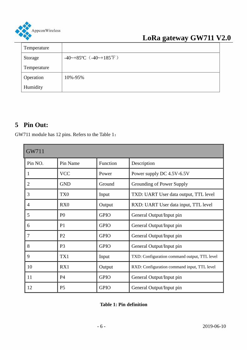
5 Pin Out:
GW711 module has 12 pins. Refers to the Table 1:
GW711
Pin NO. Pin Name Function Description
1 VCC Power Power supply DC 4.5V-6.5V
2 GND Ground Grounding of Power Supply
3 TX0 Input TXD: UART User data output, TTL level
4 RX0 Output RXD: UART User data input, TTL level
5 P0 GPIO General Output/Input pin
6 P1 GPIO General Output/Input pin
7 P2 GPIO General Output/Input pin
8 P3 GPIO General Output/Input pin
9 TX1 Input TXD: Configuration command output, TTL level
10 RX1 Output RXD: Configuration command input, TTL level
11 P4 GPIO General Output/Input pin
12 P5 GPIO General Output/Input pin
Table 1: Pin definition

LoRa gateway GW711 V2.0
- 7 - 2019-06-10
6 Dimension

LoRa gateway GW711 V2.0
- 8 - 2019-06-10
1-12
GPRS Antenna Port
LoRa Antenna Port
7 Parameter Configuration
7.1 GPRS/4G configuration
1, Connecting gateway with the Windows Laptop. User can adopt USB adapter connect gateway with
laptop via USB port. As it is shown in 7.1
After finish the hardware connection, users can insert the SIM card into the gateway and power it on.
For 2G: The red light is always on. When the yellow light flashes and the green light flashes slowly, the
Gateway initialization is complete before the setting operation can be performed.
For 4G: The red light is always on, waiting for the yellow light to finish flashing, the blue light is on to
LoRa gateway GW711 V2.0
- 9 - 2019-06-10
indicate that there is 4G signal, the red light is on to indicate that there are other network signals,
and the Gateway initialization is completed before the setting operation can be performed.
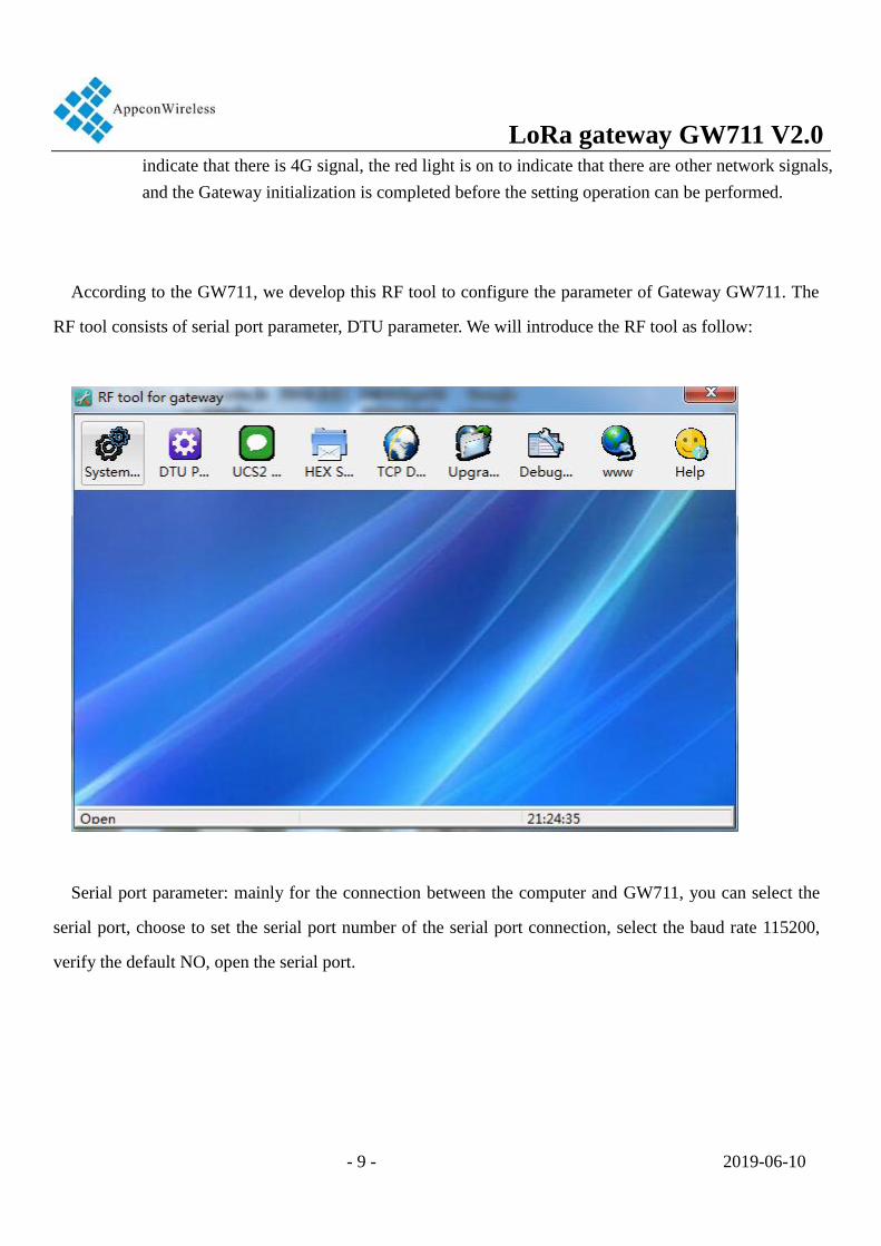
According to the GW711, we develop this RF tool to configure the parameter of Gateway GW711. The
RF tool consists of serial port parameter, DTU parameter. We will introduce the RF tool as follow:
Serial port parameter: mainly for the connection between the computer and GW711, you can select the
serial port, choose to set the serial port number of the serial port connection, select the baud rate 115200,
verify the default NO, open the serial port.

LoRa gateway GW711 V2.0
- 10 - 2019-06-10
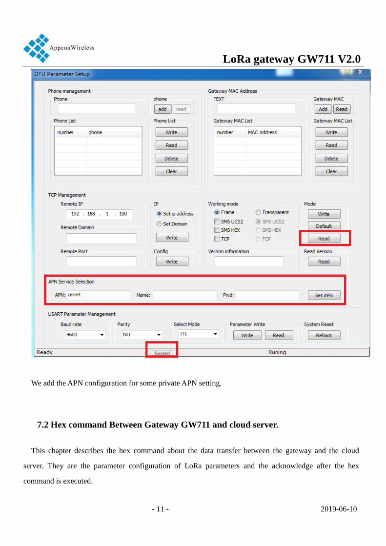
DTU parameter setting: mainly used for TCP server management of modules to add server address and
port number
Communication ID Management: Read Gateway MAC address
Successful setting will have a success reminder in the bottom.
LoRa gateway GW711 V2.0
- 11 - 2019-06-10
We add the APN configuration for some private APN setting.
7.2 Hex command Between Gateway GW711 and cloud server.
This chapter describes the hex command about the data transfer between the gateway and the cloud
server. They are the parameter configuration of LoRa parameters and the acknowledge after the hex
command is executed.

LoRa gateway GW711 V2.0
- 12 - 2019-06-10
Hex command Structure:
Head
code
Gateway
MAC address
Command
Class
Command
Type
Length data CRC End
bit
0X68 6 bytes 1 byte 1 byte LEN(2 bytes) N bytes CRC(2bytes) 0X16
Frame header: Fixed 0x68.
Gateway MAC address: The Mac address of gateway. This is Gateway ID that can not be modified.
Command Class: The class of hex command.
Command Type: The type of hex command.
Data Length: The length of the data. It indicates how many bytes the data have.
Data: Data that needs to be delivered or excuted.
Check CRC: Check the previous data for CRC16.
End of frame: fixed 0x16.
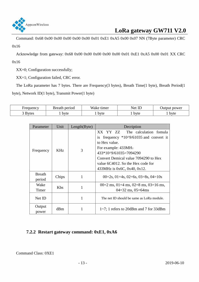
7.2.1 LoRa parameter configuration command: 0xE1, 0xA5
Command Class: 0XE1
Command Type: 0xA5
Command Description: This command is used for lora parameter configuration of GW711.
E.g: (0x00 0x00 0x00 0x00 0x00 0x01 is the mac address of gateway)
LoRa gateway GW711 V2.0
- 13 - 2019-06-10
Command: 0x68 0x00 0x00 0x00 0x00 0x00 0x01 0xE1 0xA5 0x00 0x07 NN (7Byte parameter) CRC
0x16
Acknowledge from gateway: 0x68 0x00 0x00 0x00 0x00 0x00 0x01 0xE1 0xA5 0x00 0x01 XX CRC
0x16
XX=0; Configuration successfully;
XX=1; Configuration failed, CRC error.
The LoRa parameter has 7 bytes. There are Frequency(3 bytes), Breath Time(1 byte), Breath Period(1
byte), Network ID(1 byte), Transmit Power(1 byte)
Frequency Breath period Wake timer Net ID Output power
3 Bytes 1 byte 1 byte 1 byte 1 byte
Parameter Unit Length(Byte) Decription
Frequency KHz 3
XX YY ZZ The calculation fomula
is frequency *10^9/61035 and convert it
to Hex value.
For example: 433MH:
433*10^9/61035=7094290
Convert Demical value 7094290 to Hex
value 6C4012. So the Hex code for
433MHz is 0x6C, 0x40, 0x12.
Breath
period Chips 1 00=2s, 01=4s, 02=6s, 03=8s, 04=10s
Wake
Timer Kbs 1
00=2 ms, 01=4 ms, 02=8 ms, 03=16 ms,
04=32 ms, 05=64ms
Net ID
1 The net ID should be same as LoRa module.
Output
power dBm 1 1~7; 1 refers to 20dBm and 7 for 33dBm
7.2.2 Restart gateway command: 0xE1, 0xA6
Command Class: 0XE1
LoRa gateway GW711 V2.0
- 14 - 2019-06-10
Command Type: 0xA6
Command Description: This command is used for restart gateway.
E.g: (0x00 0x00 0x00 0x00 0x00 0x01 is the mac address of gateway)
Command: 0x68 0x00 0x00 0x00 0x00 0x00 0x01 0xE1 0xA6 0x00 0x01 0x00 CRC 0x16
Acknowledge from gateway: 0x68 0x00 0x00 0x00 0x00 0x00 0x01 0xE1 0xA6 0x00 0x01 XX CRC
0x16
XX=0; Restart successfully;
XX=1; Restart failed, CRC error.
7.2.3 Set the cloud server domain of Gateway
Command Class: 0XE1
Command Type: 0xA7
Command Description: This command is used for set the cloud server domain of Gateway.
E.g: (0x00 0x00 0x00 0x00 0x00 0x01 is the mac address of gateway)
Command: 0x68 0x00 0x00 0x00 0x00 0x00 0x01 0xE1 0xA7 0x00 0x26 “www.appconwireless.com”
CRC 0x16
Acknowledge from gateway: 0x68 0x00 0x00 0x00 0x00 0x00 0x01 0xE1 0xA7 0x00 0x01 XX CRC
0x16
XX=0; Set successfully;
XX=1; Set failed, CRC error.
www.appconwireless.com is the domain of cloud server.Users should be active the parameter after the
gateway restart.

LoRa gateway GW711 V2.0
- 15 - 2019-06-10
7.2.4 Set the cloud server IP of gateway
Command Class: 0XE1
Command Type: 0xA8
Command Description: This command is used for set the cloud server IP of Gateway.
E.g: (0x00 0x00 0x00 0x00 0x00 0x01 is the mac address of gateway)
Command: 0x68 0x00 0x00 0x00 0x00 0x00 0x01 0xE1 0xA8 0x00 0x04 AA BB CC DD CRC 0x16
Acknowledge from gateway: 0x68 0x00 0x00 0x00 0x00 0x00 0x01 0xE1 0xA8 0x00 0x01 XX CRC
0x16
XX=0; Set successfully;
XX=1; Set failed, CRC error.
AA BB CC DD is the IP of cloud server. Users should be active the parameter after the gateway restart.
7.2.5 Set the cloud server port of gateway
Command Class: 0XE1
Command Type: 0xA9
Command Description: This command is used for set the cloud server port of Gateway.
E.g: (0x00 0x00 0x00 0x00 0x00 0x01 is the mac address of gateway)
Command: 0x68 0x00 0x00 0x00 0x00 0x00 0x01 0xE1 0xA9 0x00 0x02 AA BB CRC 0x16
Acknowledge from gateway: 0x68 0x00 0x00 0x00 0x00 0x00 0x01 0xE1 0xA9 0x00 0x01 XX CRC
0x16

LoRa gateway GW711 V2.0
- 16 - 2019-06-10
XX=0; Set successfully;
XX=1; Set failed, CRC error.
AA BB is the port of cloud server. Users should be active the parameter after the gateway restart.
7.2.6 Read the cloud server IP of gateway
Command Class: 0XE1
Command Type: 0xAA
Command Description: This command is used for read the cloud server IP of Gateway.
E.g: (0x00 0x00 0x00 0x00 0x00 0x01 is the mac address of gateway)
Command: 0x68 0x00 0x00 0x00 0x00 0x00 0x01 0xE1 0xAA 0x00 0x01 00 CRC 0x16
Acknowledge from gateway: 0x68 0x00 0x00 0x00 0x00 0x00 0x01 0xE1 0xA9 0x00 0x01 XX CRC
0x16
XX is the port of Cloud server.
7.2.7 Read the LoRa parameter of gateway
Command Class: 0XE1
Command Type: 0xAB
Command Description: This command is used for read the LoRa parameter of Gateway.
E.g: (0x00 0x00 0x00 0x00 0x00 0x01 is the mac address of gateway)

LoRa gateway GW711 V2.0
- 17 - 2019-06-10
Command: 0x68 0x00 0x00 0x00 0x00 0x00 0x01 0xE1 0xAB 0x00 0x01 00 CRC 0x16
Acknowledge from gateway: 0x68 0x00 0x00 0x00 0x00 0x00 0x01 0xE1 0xAB 0x00 0x07 XX CRC
0x16
XX is the lora parameter.
7.2.8 Cloud server send the data to the Lora module via gateway(Central and
Node mode)
Command Class: 0XE4
Command Type: 0xA1
Command Description: This command is used for Cloud server send the data to LoRa module via the
Gateway.The lora module is in the CAD listening mode such as RF1276T module. The gateway send the
preamble to wake up the lora module. The RF1276T module should be set as Node module. The Gateway
is running in the Central mode.
E.g: (0x00 0x00 0x00 0x00 0x00 0x01 is the mac address of gateway)
Command: 0x68 0x00 0x00 0x00 0x00 0x00 0x01 0xE4 0xA1 NN(2 Bytes) MM(data) CRC 0x16
There is no acknowledge from gateway.
NN is the length of data.
The LoRa module RF1276T should be in the Node mode. It opens the CAD listening fucntion to receive
the preamble from gateway. The parameters of wake timer, breath period and network ID should be the
same for both gateway GW711 and RF1276T module.
7.2.9 Cloud server send the data to the Lora module via gateway(Standard
mode)
Command Class: 0XE4

LoRa gateway GW711 V2.0
- 18 - 2019-06-10
Command Type: 0xA2
Command Description: This command is used for Cloud server send the data to LoRa module via the
Gateway. The LoRa module is in the standard mode such as RF1276, RF1276T and RF1276D27.
E.g: (0x00 0x00 0x00 0x00 0x00 0x01 is the mac address of gateway)
Command: 0x68 0x00 0x00 0x00 0x00 0x00 0x01 0xE4 0xA2 NN(2 Bytes) MM(data) CRC 0x16
There is no acknowledge from gateway.
NN is the length of data.
Gateway RF1276 parameter
Wake timer 2ms RF_factor 128 RF_BW 125K
Wake timer 4ms RF_factor 256 RF_BW 125K
Wake timer 8ms RF_factor 512 RF_BW 125K
Wake timer 16ms RF_factor 1024 RF_BW 125K
Wake timer 32ms RF_factor 4096 RF_BW 250K
Wake timer 64ms RF_factor 4096 RF_BW 125K
7.2.10 Cloud server send the data to the Lora module via gateway(Express
communication mode)
Command Class: 0XE4
Command Type: 0xA3
Command Description: This command is used for Cloud server send the data to LoRa module via the
Gateway. The LoRa module is RF1276T and RF1276TS. The RF1276T is in the Node mode and run at
Express communication mode.
E.g: (0x00 0x00 0x00 0x00 0x00 0x01 is the mac address of gateway)
Command: 0x68 0x00 0x00 0x00 0x00 0x00 0x01 0xE4 0xA3 NN(2 Bytes) MM(data) CRC 0x16
There is no acknowledge from gateway.

LoRa gateway GW711 V2.0
- 19 - 2019-06-10
NN is the length of data.
7.2.11 The heart-beat data packet between Cloud server and the gateway
Command Class: 0XE5
Command Type: 0x00
Command Description: This command is used for the heart-beat packet between Cloud server and
gateway.
E.g: (0x00 0x00 0x00 0x00 0x00 0x01 is the mac address of gateway)
Command: 0x68 0x00 0x00 0x00 0x00 0x00 0x01 0xE5 0x00 NN(2 Bytes) MM(data) CRC 0x16
There is no acknowledge from gateway.
NN is the length of data.
MM is the data which can be customized by user.
Note: After logging into the server, The heart-beat packet is the gateway send to the cloud server. If there
are other commands, the heartbeat will be delayed. The period of heart-beat packet is 40 second .
GW711 resever the DTU transparent transmission function. If the cloud server sends the data not in the
format of hex command, the data will output from the user data serial port(3 pin, 4 pin). And also the user
data serial port will transfer the data to cloud server.
8 Order information

LoRa gateway GW711 V2.0
- 20 - 2019-06-10
a) GW711-GPRS
b) GW711-LTE
9 Q&A:
Questions and Answers
Can not
communicate
between two
devices
1.The communication protocol is different between two modules, for
instance: data rate and checkout.
2.The frequency or RF data rate is different between two communicated
modules.
3.They are not the same kind products.
4.The connection between module and terminal is wrong.
5、The module is wrong.
6.The setting of EN is wrong.
7.The communication distance exceeds the range, or the connection of
antenna is bad.
Short 1.The supply voltage exceeds range
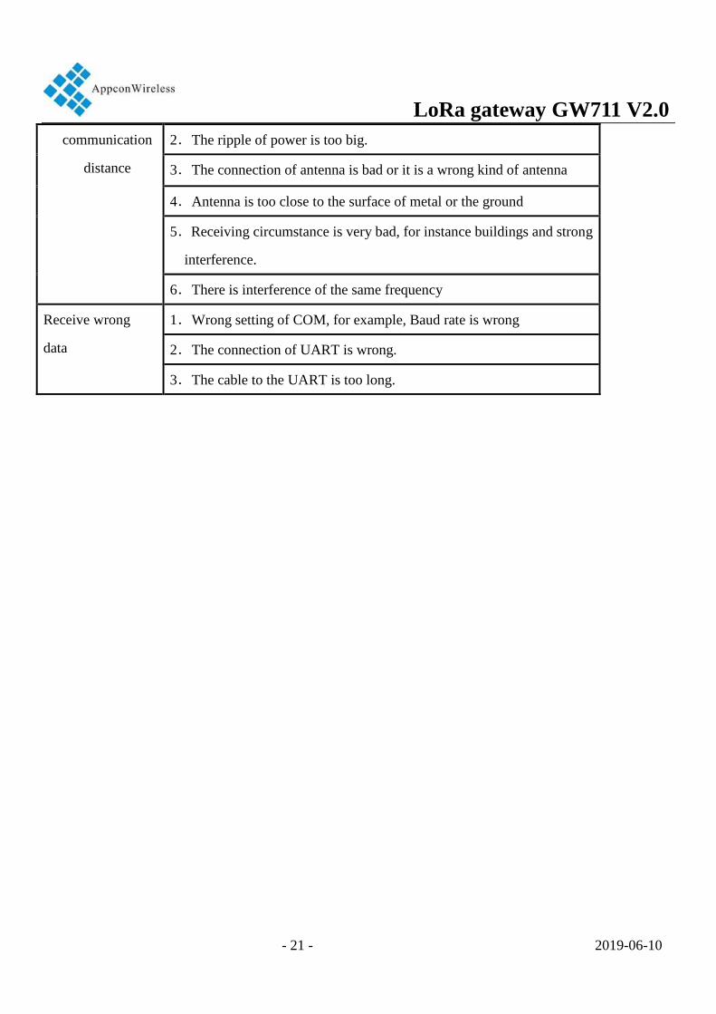
LoRa gateway GW711 V2.0
- 21 - 2019-06-10
communication
distance
2.The ripple of power is too big.
3.The connection of antenna is bad or it is a wrong kind of antenna
4.Antenna is too close to the surface of metal or the ground
5.Receiving circumstance is very bad, for instance buildings and strong
interference.
6.There is interference of the same frequency
Receive wrong
data
1.Wrong setting of COM, for example, Baud rate is wrong
2.The connection of UART is wrong.
3.The cable to the UART is too long.
LoRa gateway GW711 V2.0
- 22 - 2019-06-10
APPCON WIRELESS TECHNOLOGIES CO.,LTD
Add: 28#, Longjin road,Xili zone, Nanshan District
Shenzhen P.R.C(518043)
TEL: +86-185 0309 2598
FAX: +86-755-83405160
Email: [email protected]
Web: http://www.appconwireless.com
AppconWireless technologies reserves the right to
make corrections, modifications, improvements and
other changes to its products and services at any
time and to discontinue any product or service
without notice. Customers are expected to visit
websites for getting newest product information
before placing orders.
These products are not designed for use in life
support appliances, devices or other products where
malfunction of these products might result in
personal injury. Customers using these products in
such applications do so at their own risk and agree
to fully indemnify AppconWireless technologies for
any damages resulting from improper use