Embed Size (px)
Citation preview

86
The TaskPreventing measuring errors or even destruction of the system normally requires floating connection of the sensors and actuators to the sensitive MSR electronics.
The Problemwas solved up to now with additional devices for electrical isolation downstream from the routing and distributor level.
The Solutionis the 6-mm wide IsoTrans B 48 isolating terminal. It meets all requirements for a modern terminal and isolates 0(4) ... 20 mA signals safely and reliably without an exter-nal power supply, without falsifying the measurement signal itself.
The Connectionsuse Z-spring technology and allow for sim-ple, fast and safe connection of the wires.
The TechnologyThe extremely narrow housing with a width of just 6 mm was achieved by constantly improving the circuit design of our tried-and-tested isolators, which draw their power as a voltage drop from the measure-ment signal, and the use of a specially developed flat-core transformer. This allows connecting up to 166 isolating terminals per meter of mounting rail.
Loop-Powered Isolators for Standard Signals
IsoTrans B 48Clamp on to simple isolation! 20 mA transmission with electrical isolation.

For up-to-date information, please visit www.knick.de
The Facts
87
Isol
atio
n A
mpl
ifier
sTr
ansm
itte
rs
Indic
ator
s
Proc
ess A
nalyt
ics
Porta
ble M
eter
s
Labo
rato
ry M
eter
s
Sens
ors
Fittin
gs
– Substantial cost- and space-savings due to the elimination of a whole installation stage
– Minimum wiring effort due to loop-powered isolation and the combination of terminal and iso-lator in one device
– Fast, simple and safe wiring using Z-springs
– A high level of safety through proven circuit technology
– Galvanic isolation Protection against incorrect mea-surements or damage to the equip-ment due to parasitic voltages
– Extremely compact design The slim 6-mm housing allows up to 166 channels per meter
– Easy to use and service Simple and fast installation due to innovative Z-spring technology
– No power supply required Cost savings due to lower wiring effort, no mains interference
– High accuracy No distortion of the measurement signal
– 5-year warranty
Warranty
5 years!Warranty
Defects occurring within 5 years from delivery date shall be remedied free of
charge at our plant (carriage and insurance paid by sender).
88
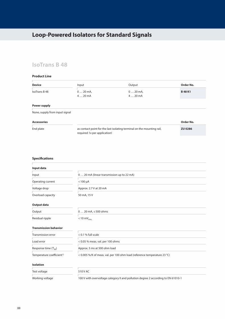
Product Line
IsoTrans B 48
Loop-Powered Isolators for Standard Signals
Specifications
Input data
Input 0 … 20 mA (linear transmission up to 22 mA)
Operating current < 100 µA
Voltage drop Approx. 2.7 V at 20 mA
Overload capacity 50 mA, 15 V
Output data
Output 0 … 20 mA, ≤ 500 ohms
Residual ripple < 10 mVrms
Transmission behavior
Transmission error < 0.1 % full scale
Load error < 0.05 % meas. val. per 100 ohms
Response time (T99) Approx. 5 ms at 500 ohm load
Temperature coefficient1) < 0.005 %/K of meas. val. per 100 ohm load (reference temperature 23 °C)
Isolation
Test voltage 510 V AC
Working voltage 100 V with overvoltage category II and pollution degree 2 according to EN 61010-1
Device Input Output Order No.
IsoTrans B 48 0 … 20 mA, 4 … 20 mA
0 … 20 mA, 4 … 20 mA
B 48 K1
Power supply
None, supply from input signal
Accessories Order No.
End plate as contact point for the last isolating terminal on the mounting rail, required 1x per application!
ZU 0286

For up-to-date information, please visit www.knick.de
89
Isol
atio
n A
mpl
ifier
sTr
ansm
itte
rs
Indic
ator
s
Proc
ess A
nalyt
ics
Porta
ble M
eter
s
Labo
rato
ry M
eter
s
Sens
ors
Fittin
gs
Specifications (continued)
Standards and approvals
EMC2) 89/336/EEC, EN 61326
Further data
Ambient temperature Operation: –25 … +60 °C also when mounted in row Transport and storage: -40 … +85 °C
Design Terminal housing, 6 mm wide, Z-spring terminal See dimension drawings for further measurements
Ingress protection IP 20 when mounted in row or with end plate
Mounting For 35-mm mounting rail according to EN 50022 See dimension drawings for conductor cross-section
Weight 12 g
1) Average TC in the specified operating temperature range –25 … +60 °C 2) Applies to 4 … 20 mA, slight deviations are possible while there is interference

90
IsoTrans B 48
Loop-Powered Isolators for Standard Signals
Input Voltage
Block Diagram
Depending on the load at Iout = 20 mA
Input 0 … 20 mA
+
–
Z 18 V C330 nF Output 0 … 20 mA
+
–
12.5
10
7.5
5
2.5
0
Vin / V
RL / ohm Vout / V
0 0
100 2
200 4
Z 18 VC330 nF
300 6
400 8
500 10

For up-to-date information, please visit www.knick.de
91
Isol
atio
n A
mpl
ifier
sTr
ansm
itte
rs
Indic
ator
s
Proc
ess A
nalyt
ics
Porta
ble M
eter
s
Labo
rato
ry M
eter
s
Sens
ors
Fittin
gs
Dimension Drawings and Terminal Assignments
Terminal assignments 1 Input + 2 Input – 3 Power supply AC/DC 4 Output – 5 Output + Conductor cross-sections: single wire 0.5 … 2.5 mm2 stranded wire 0.5 … 2.5 mm2 with ferrule 0.5 … 1.5 mm2
End plate ZU 0286, 1.5 mm wide, for contact protection, only required for the last isolator on the mounting rail
56
63
6
91
All dimensions in mm