Embed Size (px)
Citation preview
Looking through walls - Coatings on glass for buildings
by Wolfgang Theiss
M. Theiss – Hard- and Software for Optical Spectroscopy, Dr.-Bernhard-Klein-Str. 110, D-52078 Aachen, Germany
Abstract
Modern buildings are equipped with windows having thermal insulatingproperties like solid walls. Advanced thin film coatings not only efficientlysuppress the emission of heat radiation but provide a large variety of possiblecolors for architectural design. Optical spectroscopy from the ultraviolet to theinfrared plays an important role in the development of these products. Therelation between deposition conditions and optical properties of the producedmaterials is studied, and the interaction of the individual layers with theirneighbours in the stack is investigated. The optical design of optimizedmultilayers and spectroscopic production control is discussed.
Moderne Gebäude sind mit Fenstern ausgestattet, die thermisch so gutisolieren wie massive Wände. Die dabei eingesetzten Dünnschichtsystemeunterdrücken effizient die Wärmeabstrahlung des Glases und gebengleichzeitig dem Architekten eine grosse Gestaltungsmöglichkeit bezüglich derFarbe der Verglasung. Optische Spektroskopie vom ultravioletten bis zuminfraroten Spektralbereich spielt eine große Rolle bei der Entwicklung dieserProdukte. Der Zusammenhang zwischen den Depositionsbedingungen und denerzielten optischen Eigenschaften der produzierten Materialien sowie dieWechselwirkung der einzelnen Schichten mit ihren Nachbarn imSchichtsystem werden untersucht. Das optische Design derVielfachschichtsysteme und die spektroskopische Produktionskontrolle werdendiskutiert.
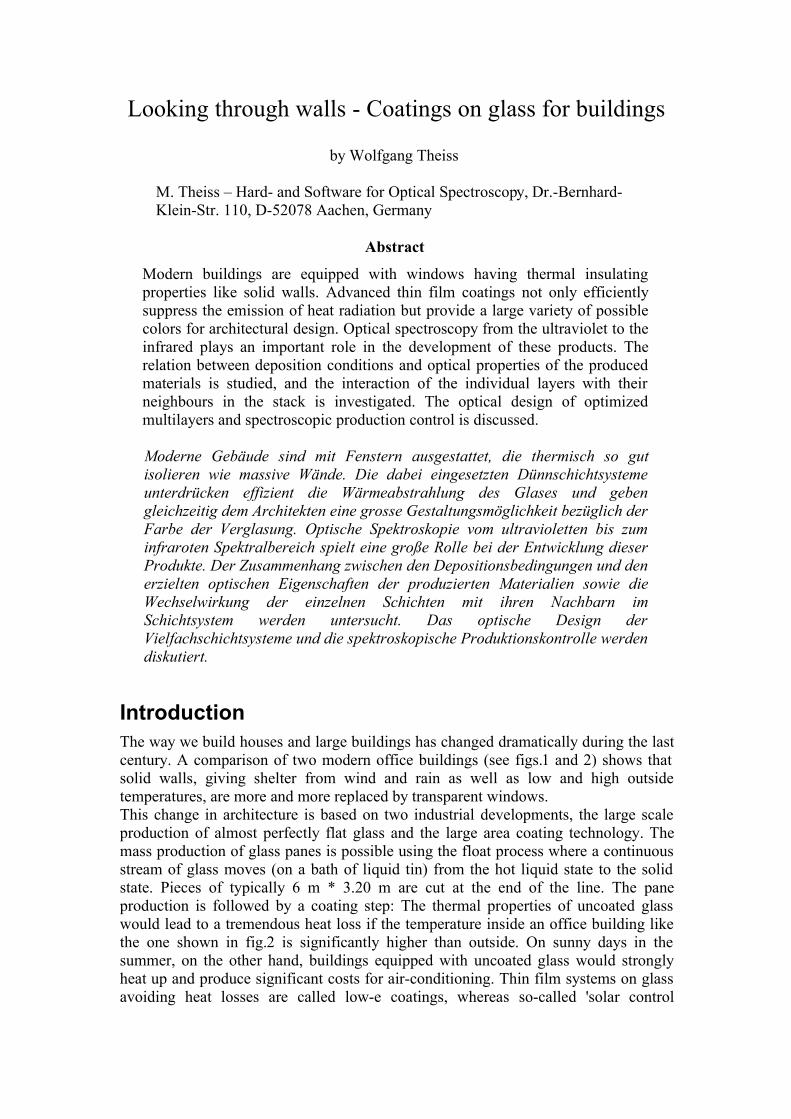
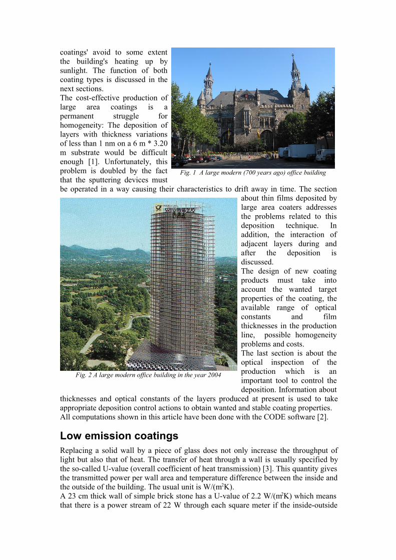
IntroductionThe way we build houses and large buildings has changed dramatically during the lastcentury. A comparison of two modern office buildings (see figs.1 and 2) shows thatsolid walls, giving shelter from wind and rain as well as low and high outsidetemperatures, are more and more replaced by transparent windows.This change in architecture is based on two industrial developments, the large scaleproduction of almost perfectly flat glass and the large area coating technology. Themass production of glass panes is possible using the float process where a continuousstream of glass moves (on a bath of liquid tin) from the hot liquid state to the solidstate. Pieces of typically 6 m * 3.20 m are cut at the end of the line. The paneproduction is followed by a coating step: The thermal properties of uncoated glasswould lead to a tremendous heat loss if the temperature inside an office building likethe one shown in fig.2 is significantly higher than outside. On sunny days in thesummer, on the other hand, buildings equipped with uncoated glass would stronglyheat up and produce significant costs for air-conditioning. Thin film systems on glassavoiding heat losses are called low-e coatings, whereas so-called 'solar control
coatings' avoid to some extentthe building's heating up bysunlight. The function of bothcoating types is discussed in thenext sections.The cost-effective production oflarge area coatings is apermanent struggle forhomogeneity: The deposition oflayers with thickness variationsof less than 1 nm on a 6 m * 3.20m substrate would be difficultenough [1]. Unfortunately, thisproblem is doubled by the factthat the sputtering devices mustbe operated in a way causing their characteristics to drift away in time. The section
about thin films deposited bylarge area coaters addressesthe problems related to thisdeposition technique. Inaddition, the interaction ofadjacent layers during andafter the deposition isdiscussed.The design of new coatingproducts must take intoaccount the wanted targetproperties of the coating, theavailable range of opticalconstants and filmthicknesses in the productionline, possible homogeneityproblems and costs.The last section is about theoptical inspection of theproduction which is animportant tool to control thedeposition. Information about
thicknesses and optical constants of the layers produced at present is used to takeappropriate deposition control actions to obtain wanted and stable coating properties.All computations shown in this article have been done with the CODE software [2].
Low emission coatingsReplacing a solid wall by a piece of glass does not only increase the throughput oflight but also that of heat. The transfer of heat through a wall is usually specified bythe so-called U-value (overall coefficient of heat transmission) [3]. This quantity givesthe transmitted power per wall area and temperature difference between the inside andthe outside of the building. The usual unit is W/(m2K). A 23 cm thick wall of simple brick stone has a U-value of 2.2 W/(m2K) which meansthat there is a power stream of 22 W through each square meter if the inside-outside
Fig. 1 A large modern (700 years ago) office building
Fig. 2 A large modern office building in the year 2004
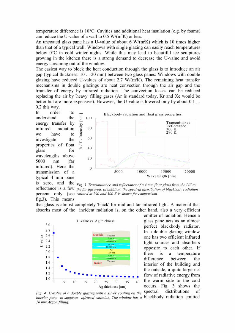
temperature difference is 10°C. Cavities and additional heat insulation (e.g. by foams)can reduce the U-value of a wall to 0.5 W/(m2K) or less.An uncoated glass pane has a U-value of about 6 W/(m2K) which is 10 times higherthan that of a typical wall. Windows with single glazing can easily reach temperaturesbelow 0°C in cold winter nights. While this may lead to beautiful ice sculpturesgrowing in the kitchen there is a strong demand to decrease the U-value and avoidenergy streaming out of the window.The easiest way to block the heat conduction through the glass is to introduce an airgap (typical thickness: 10 ... 20 mm) between two glass panes: Windows with doubleglazing have reduced U-values of about 2.7 W/(m2K). The remaining heat transfermechanisms in double glazings are heat convection through the air gap and thetrransfer of energy by infrared radiation. The convection losses can be reducedreplacing the air by 'heavy' filling gases (Ar is standard today, Kr and Xe would bebetter but are more expensive). However, the U-value is lowered only by about 0.1 ...0.2 this way.In order tounderstand theenergy transfer byinfrared radiationwe have toinvestigate theproperties of floatglass forwavelengths above5000 nm (farinfrared). Here thetransmission of atypical 4 mm paneis zero, and thereflectance is a fewpercent only (seefig.3). This meansthat glass is almost completely 'black' for mid and far infrared light. A material thatabsorbs most of the incident radiation is, on the other hand, also a very efficient
emitter of radiation. Hence aglass pane acts as an almostperfect blackbody radiator.In a double glazing windowone has two efficient infraredlight sources and absorbersopposite to each other. Ifthere is a temperaturedifference between theinterior of the building andthe outside, a quite large netflow of radiative energy fromthe warm side to the coldoccurs. Fig. 3 shows thespectral distributions ofblackbody radiation emitted
Fig. 3 Transmittance and reflectance of a 4 mm float glass from the UV tothe far infrared. In addition, the spectral distribution of blackbody radiationemitted at 290 and 300 K is shown for comparison.
Blackbody radiation and float glass properties
5000 10000 15000 20000Wavelength [nm]
0
20
40
60
80
100
R /
T /
Inte
nsity
[a.
u.]
TransmittanceReflectance300 K290 K
Fig. 4 U-value of a double glazing with a silver coating on theinterior pane to suppress infrared emission. The window has a16 mm Argon filling.
U-value vs. Ag thickness
0 5 10 15 20 25 30 35 40Ag thickness [nm]
1.01.21.41.61.82.02.22.42.62.83.0
U-v
alue Vacuum
Float A4.000 mm
Argon16.000 mm
Ag12.0 nmFloat A
4.000 mmVacuumInside
Outside
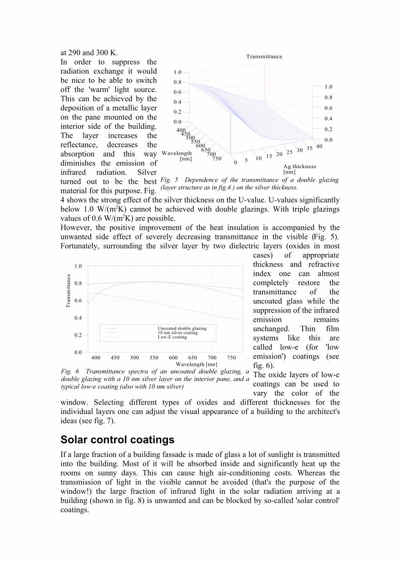
at 290 and 300 K.In order to suppress theradiation exchange it wouldbe nice to be able to switchoff the 'warm' light source.This can be achieved by thedeposition of a metallic layeron the pane mounted on theinterior side of the building.The layer increases thereflectance, decreases theabsorption and this waydiminishes the emission ofinfrared radiation. Silverturned out to be the bestmaterial for this purpose. Fig.4 shows the strong effect of the silver thickness on the U-value. U-values significantlybelow 1.0 W/(m2K) cannot be achieved with double glazings. With triple glazingsvalues of 0.6 W/(m2K) are possible.However, the positive improvement of the heat insulation is accompanied by theunwanted side effect of severely decreasing transmittance in the visible (Fig. 5).Fortunately, surrounding the silver layer by two dielectric layers (oxides in most
cases) of appropriatethickness and refractiveindex one can almostcompletely restore thetransmittance of theuncoated glass while thesuppression of the infraredemission remainsunchanged. Thin filmsystems like this arecalled low-e (for 'lowemission') coatings (seefig. 6).The oxide layers of low-ecoatings can be used tovary the color of the
window. Selecting different types of oxides and different thicknesses for theindividual layers one can adjust the visual appearance of a building to the architect'sideas (see fig. 7).
Solar control coatingsIf a large fraction of a building fassade is made of glass a lot of sunlight is transmittedinto the building. Most of it will be absorbed inside and significantly heat up therooms on sunny days. This can cause high air-conditioning costs. Whereas thetransmission of light in the visible cannot be avoided (that's the purpose of thewindow!) the large fraction of infrared light in the solar radiation arriving at abuilding (shown in fig. 8) is unwanted and can be blocked by so-called 'solar control'coatings.
Fig. 5 Dependence of the transmittance of a double glazing(layer structure as in fig.4 ) on the silver thickness.
400 450
500 550
600 650
700 750
Wavelength[nm]
0 5 10 15 20 25 30 35 40
Ag thickness[nm]
0.0
0.2
0.4
0.6
0.8
1.0
0.0
0.2
0.4
0.6
0.8
1.0
Transmittance
Fig. 6 Transmittance spectra of an uncoated double glazing, adouble glazing with a 10 nm silver layer on the interior pane, and atypical low-e coating (also with 10 nm silver)
400 450 500 550 600 650 700 750Wavelength [nm]
0.0
0.2
0.4
0.6
0.8
1.0
Tra
nsm
ittan
ce
Uncoated double glazing10 nm silver coatingLow-E coating
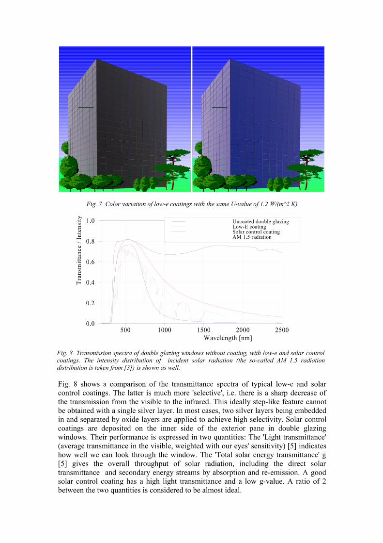
Fig. 8 shows a comparison of the transmittance spectra of typical low-e and solarcontrol coatings. The latter is much more 'selective', i.e. there is a sharp decrease ofthe transmission from the visible to the infrared. This ideally step-like feature cannotbe obtained with a single silver layer. In most cases, two silver layers being embeddedin and separated by oxide layers are applied to achieve high selectivity. Solar controlcoatings are deposited on the inner side of the exterior pane in double glazingwindows. Their performance is expressed in two quantities: The 'Light transmittance'(average transmittance in the visible, weighted with our eyes' sensitivity) [5] indicateshow well we can look through the window. The 'Total solar energy transmittance' g[5] gives the overall throughput of solar radiation, including the direct solartransmittance and secondary energy streams by absorption and re-emission. A goodsolar control coating has a high light transmittance and a low g-value. A ratio of 2between the two quantities is considered to be almost ideal.
Fig. 7 Color variation of low-e coatings with the same U-value of 1.2 W/(m^2 K)
>><<>><<
Fig. 8 Transmission spectra of double glazing windows without coating, with low-e and solar controlcoatings. The intensity distribution of incident solar radiation (the so-called AM 1.5 radiationdistribution is taken from [3]) is shown as well.
500 1000 1500 2000 2500Wavelength [nm]
0.0
0.2
0.4
0.6
0.8
1.0
Tra
nsm
ittan
ce /
Inte
nsity Uncoated double glazing
Low-E coatingSolar control coatingAM 1.5 radiation
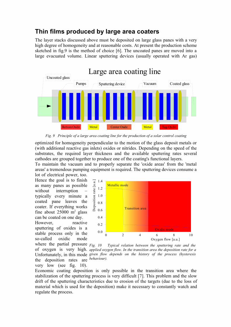
Thin films produced by large area coatersThe layer stacks discussed above must be deposited on large glass panes with a veryhigh degree of homogeneity and at reasonable costs. At present the production schemesketched in fig.9 is the method of choice [6]. The uncoated panes are moved into alarge evacuated volume. Linear sputtering devices (usually operated with Ar gas)
optimized for homogeneity perpendicular to the motion of the glass deposit metals or(with additional reactive gas inlets) oxides or nitrides. Depending on the speed of thesubstrates, the required layer thickness and the available sputtering rates severalcathodes are grouped together to produce one of the coating's functional layers.To maintain the vacuum and to properly separate the 'oxide areas' from the 'metalareas' a tremendous pumping equipment is required. The sputtering devices consume alot of electrical power, too.Hence the goal is to finishas many panes as possiblewithout interruption –typically every minute acoated pane leaves thecoater. If everything worksfine about 25000 m2 glasscan be coated on one day. However, reactivesputtering of oxides is astable process only in theso-called oxidic modewhere the partial pressureof oxygen is very high.Unfortunately, in this modethe deposition rates arevery low (see fig. 10).Economic coating deposition is only possible in the transition area where thestabilization of the sputtering process is very difficult [7]. This problem and the slowdrift of the sputtering characteristics due to erosion of the targets (due to the loss ofmaterial which is used for the deposition) make it necessary to constantly watch andregulate the process.
Fig. 9 Principle of a large area coating line for the production of a solar control coating
Uncoated glassVacuumSputtering device Coated glass
Bottom Oxide Center Oxide Top OxideMetal Metal
Large area coating linePumps
Fig. 10 Typical relation between the sputtering rate and theapplied oxygen flow. In the transition area the deposition rate for agiven flow depends on the history of the process (hysteresisbehaviour).
0 2 4 6 8 10Oxygen flow [a.u.]
0.0
0.2
0.4
0.6
0.8
1.0
1.2
1.4
Dep
ositi
on ra
te [a
.u.]
Metallic mode
Oxidic mode
Transition area
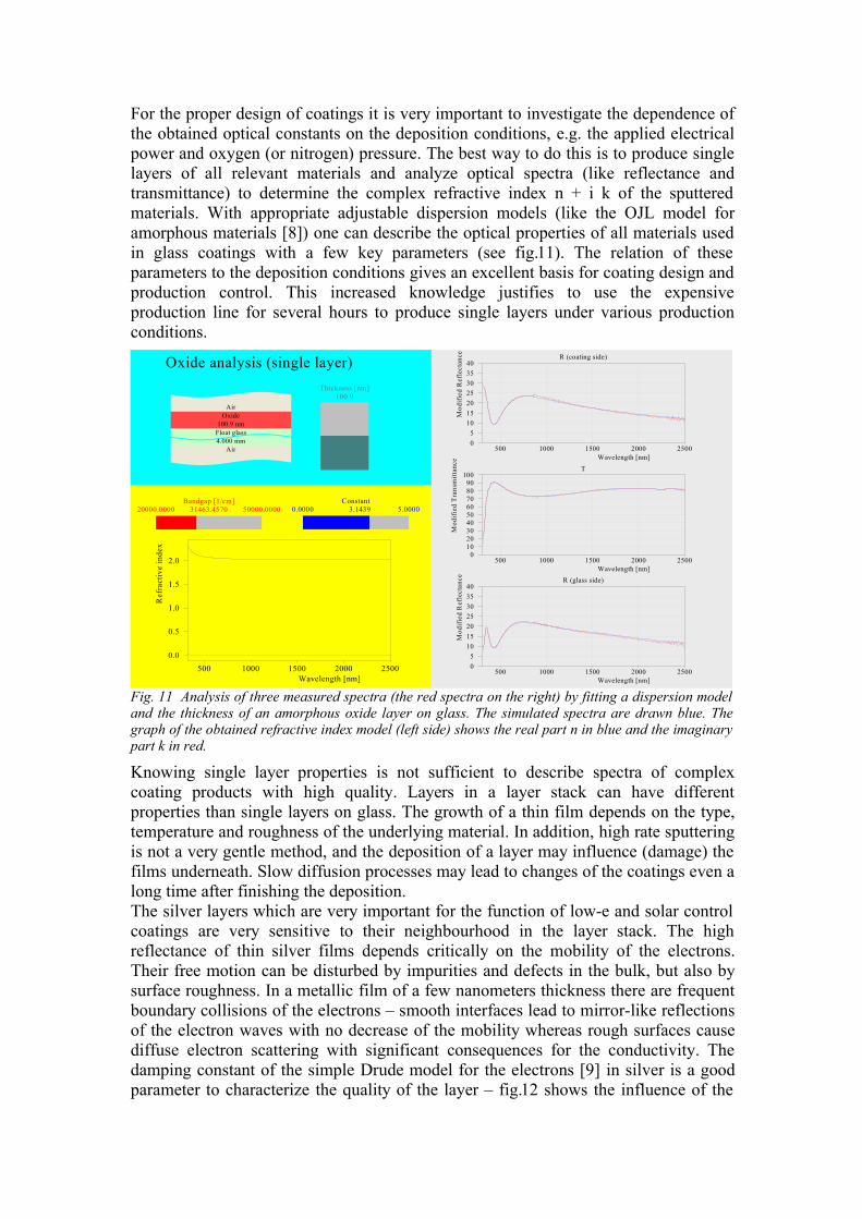
For the proper design of coatings it is very important to investigate the dependence ofthe obtained optical constants on the deposition conditions, e.g. the applied electricalpower and oxygen (or nitrogen) pressure. The best way to do this is to produce singlelayers of all relevant materials and analyze optical spectra (like reflectance andtransmittance) to determine the complex refractive index n + i k of the sputteredmaterials. With appropriate adjustable dispersion models (like the OJL model foramorphous materials [8]) one can describe the optical properties of all materials usedin glass coatings with a few key parameters (see fig.11). The relation of theseparameters to the deposition conditions gives an excellent basis for coating design andproduction control. This increased knowledge justifies to use the expensiveproduction line for several hours to produce single layers under various productionconditions.
Fig. 11 Analysis of three measured spectra (the red spectra on the right) by fitting a dispersion modeland the thickness of an amorphous oxide layer on glass. The simulated spectra are drawn blue. Thegraph of the obtained refractive index model (left side) shows the real part n in blue and the imaginarypart k in red.
Knowing single layer properties is not sufficient to describe spectra of complexcoating products with high quality. Layers in a layer stack can have differentproperties than single layers on glass. The growth of a thin film depends on the type,temperature and roughness of the underlying material. In addition, high rate sputteringis not a very gentle method, and the deposition of a layer may influence (damage) thefilms underneath. Slow diffusion processes may lead to changes of the coatings even along time after finishing the deposition.The silver layers which are very important for the function of low-e and solar controlcoatings are very sensitive to their neighbourhood in the layer stack. The highreflectance of thin silver films depends critically on the mobility of the electrons.Their free motion can be disturbed by impurities and defects in the bulk, but also bysurface roughness. In a metallic film of a few nanometers thickness there are frequentboundary collisions of the electrons – smooth interfaces lead to mirror-like reflectionsof the electron waves with no decrease of the mobility whereas rough surfaces causediffuse electron scattering with significant consequences for the conductivity. Thedamping constant of the simple Drude model for the electrons [9] in silver is a goodparameter to characterize the quality of the layer – fig.12 shows the influence of the
R (coating side)
500 1000 1500 2000 2500Wavelength [nm]
05
10152025303540
Mod
ified
Ref
lect
ance
T
500 1000 1500 2000 2500Wavelength [nm]
0102030405060708090
100
Mod
ifie
d T
rans
mitt
ance
R (glass side)
500 1000 1500 2000 2500Wavelength [nm]
05
10152025303540
Mod
ified
Ref
lect
ance
500 1000 1500 2000 2500Wavelength [nm]
0.0
0.5
1.0
1.5
2.0
Ref
ract
ive
inde
x
Oxide analysis (single layer)
AirOxide
100.9 nmFloat glass4.000 mm
Air
Thickness [nm]100.9
Bandgap [1/cm]31463.457020000.0000 50000.0000
Constant 3.14390.0000 5.0000
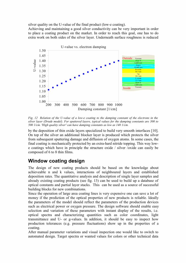
silver quality on the U-value of the final product (low-e coating). Achieving and maintaining a good silver conductivity can be very important in orderto place a coating product on the market. In order to reach this goal, one has to doextra work on both sides of the silver layer. Underneath surface roughness is reduced
by the deposition of thin oxide layers specialized to build very smooth interfaces [10].On top of the silver an additional blocker layer is produced which protects the silverfrom subsequent sputtering damage and diffusion of oxygen atoms. In some cases, thefinal coating is mechanically protected by an extra-hard nitride topping. This way low-e coatings which have in principle the structure oxide / silver /oxide can easily becomposed of 6 to 8 thin films.
Window coating designThe design of new coating products should be based on the knowledge aboutachieveable n and k values, interactions of neighboured layers and establisheddeposition rates. The quantitative analysis and description of single layer samples andalready existing coating products (see fig. 13) can be used to build up a database ofoptical constants and partial layer stacks. This can be used as a source of successfulbuilding blocks for new combinations. Since the operation of large area coating lines is very expensive one can save a lot ofmoney if the prediction of the optical properties of new products is reliable. Ideallythe parameters of the model should reflect the parameters of the production devicessuch as electrical power or oxygen pressure. The design software should enable easyselection and variation of these parameters with instant display of the results, i.e.optical spectra and characterizing quantities such as color coordinates, lighttransmittance and U- or g-values. In addition, it should be easy to inspect howproduction tolerances (e.g. pressure fluctuations) show up in the properties of acoating.After manual parameter variations and visual inspection one would like to switch toautomated design. Target spectra or wanted values for colors or other technical data
Fig. 12 Relation of the U-value of a low-e coating to the damping constant of the electrons in thesilver layer (Drude model). For sputtered layers, typical values for the damping constants are 300 to500 1/cm. 'High quality silver' can have damping constants as low as 140 1/cm.
U-value vs. electron damping
200 300 400 500 600 700 800 900 1000Damping constant [1/cm]
1.001.051.101.151.201.251.301.351.401.451.50
U-v
alue
VacuumFloat A
4.000 mmArgon
16.000 mmB-oxide56.3 nm
Ag10.1 nmC-oxide23.5 nmFloat A
4.000 mmVacuumInside
Outside
are used as optimization goals. Usually several parameters related to the thicknessesand optical constants of the model are adjusted simultaneously. For parameter fine-
tuning one can use optimization methods that move from the starting design to thenext local minimum of the deviation to the target values. This is a matter of secondsor minutes and can be mixed with manual user interactions. Methods that search forthe global deviation minimum are much slower and should not require any useractions in order to be applied in overnight optimization runs.
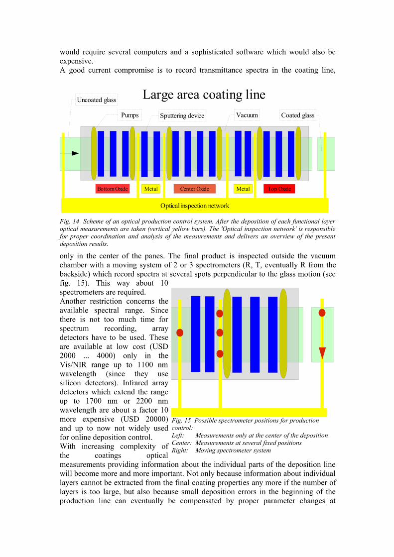
Optical production controlAs discussed above, thin film deposition in large area coating lines must be permantlyobserved and corrected. Due to the high operational costs, one must detect deviationsfrom the target properties of the coating as early as possible.Fig. 14 shows the principle of an optical production control system [6]. At everyimportant position along the production line appropriate optical measurements aredone. An 'optical network' is responsible for the coordination of the data acquisitionand analysis of the measured data. It provides status information about the presentcondition of the production line. The operator can use this information in order todecide if production parameters should be changed and which actions are required.It would be advantageous to record several spectra at each position: Reflectance fromthe coating and the glass side as well as transmittance, if possible in a large spectralrange. These spectra would provide enough information to safely determine thethickness and the optical constants of each main layer of the coating. Ideally onewould like to measure at several spots (at least 3) perpendicular to the direction of theglass motion in order to check the lateral homogeneity of the deposition. There are some limitations, however. Recording 3 spectra at 5 positions along theproduction line with 3 spots perpendicular to the line would mean to buy, install andoperate 45 spectrometers. Even if low-cost array spectrometers are used, this is justtoo expensive at the moment. Also the analysis and the handling of the obtained data
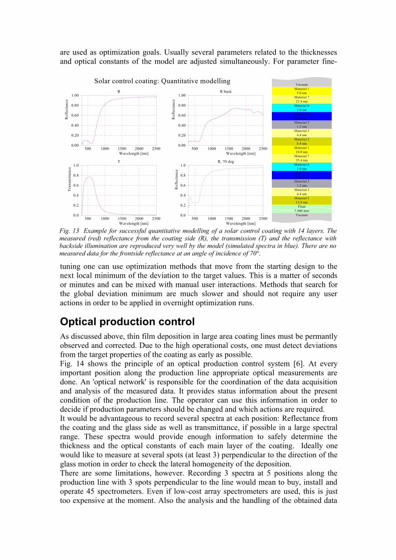
Fig. 13 Example for successful quantitative modelling of a solar control coating with 14 layers. Themeasured (red) reflectance from the coating side (R), the transmission (T) and the reflectance withbackside illumination are reproduced very well by the model (simulated spectra in blue). There are nomeasured data for the frontside reflectance at an angle of incidence of 70°.
R
500 1000 1500 2000 2500Wavelength [nm]
0.00
0.20
0.40
0.60
0.80
1.00
Ref
lect
ance
R back
500 1000 1500 2000 2500Wavelength [nm]
0.00
0.20
0.40
0.60
0.80
1.00
Ref
lect
ance
T
500 1000 1500 2000 2500Wavelength [nm]
0.0
0.2
0.4
0.6
0.8
1.0
Tra
nsm
ittan
ce
R, 70 deg
500 1000 1500 2000 2500Wavelength [nm]
0.0
0.2
0.4
0.6
0.8
1.0
Ref
lect
ance
VacuumMaterial 1
5.0 nmMaterial 721.4 nm
Material 63.0 nm
Material 410.9 nm
Material 51.2 nm
Material 34.4 nm
Material 28.4 nm
Material 110.0 nm
Material 735.4 nm
Material 63.0 nm
Material 412.2 nm
Material 51.2 nm
Material 34.4 nm
Material 213.8 nm
Float7.900 mmVacuum
Solar control coating: Quantitative modelling
would require several computers and a sophisticated software which would also beexpensive.A good current compromise is to record transmittance spectra in the coating line,
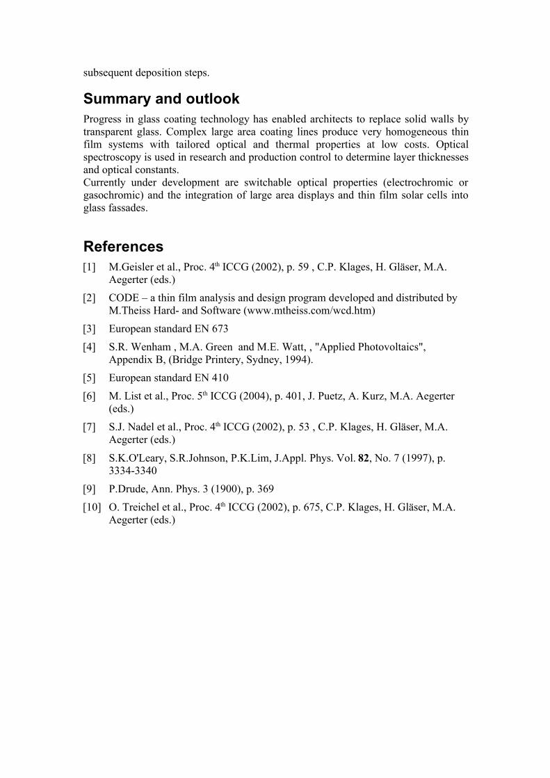
only in the center of the panes. The final product is inspected outside the vacuumchamber with a moving system of 2 or 3 spectrometers (R, T, eventually R from thebackside) which record spectra at several spots perpendicular to the glass motion (seefig. 15). This way about 10spectrometers are required.Another restriction concerns theavailable spectral range. Sincethere is not too much time forspectrum recording, arraydetectors have to be used. Theseare available at low cost (USD2000 ... 4000) only in theVis/NIR range up to 1100 nmwavelength (since they usesilicon detectors). Infrared arraydetectors which extend the rangeup to 1700 nm or 2200 nmwavelength are about a factor 10more expensive (USD 20000)and up to now not widely usedfor online deposition control.With increasing complexity ofthe coatings opticalmeasurements providing information about the individual parts of the deposition linewill become more and more important. Not only because information about individuallayers cannot be extracted from the final coating properties any more if the number oflayers is too large, but also because small deposition errors in the beginning of theproduction line can eventually be compensated by proper parameter changes at
Fig. 14 Scheme of an optical production control system. After the deposition of each functional layeroptical measurements are taken (vertical yellow bars). The 'Optical inspection network' is responsiblefor proper coordination and analysis of the measurements and delivers an overview of the presentdeposition results.
Uncoated glass
VacuumSputtering device Coated glass
Bottom Oxide Center Oxide Top OxideMetal Metal
Large area coating linePumps
Optical inspection network
Fig. 15 Possible spectrometer positions for productioncontrol:Left: Measurements only at the center of the depositionCenter: Measurements at several fixed positionsRight: Moving spectrometer system
subsequent deposition steps.
Summary and outlookProgress in glass coating technology has enabled architects to replace solid walls bytransparent glass. Complex large area coating lines produce very homogeneous thinfilm systems with tailored optical and thermal properties at low costs. Opticalspectroscopy is used in research and production control to determine layer thicknessesand optical constants.Currently under development are switchable optical properties (electrochromic orgasochromic) and the integration of large area displays and thin film solar cells intoglass fassades.
References[1] M.Geisler et al., Proc. 4th ICCG (2002), p. 59 , C.P. Klages, H. Gläser, M.A.
Aegerter (eds.)
[2] CODE – a thin film analysis and design program developed and distributed byM.Theiss Hard- and Software (www.mtheiss.com/wcd.htm)
[3] European standard EN 673
[4] S.R. Wenham , M.A. Green and M.E. Watt, , "Applied Photovoltaics",Appendix B, (Bridge Printery, Sydney, 1994).
[5] European standard EN 410
[6] M. List et al., Proc. 5th ICCG (2004), p. 401, J. Puetz, A. Kurz, M.A. Aegerter(eds.)
[7] S.J. Nadel et al., Proc. 4th ICCG (2002), p. 53 , C.P. Klages, H. Gläser, M.A.Aegerter (eds.)
[8] S.K.O'Leary, S.R.Johnson, P.K.Lim, J.Appl. Phys. Vol. 82, No. 7 (1997), p.3334-3340
[9] P.Drude, Ann. Phys. 3 (1900), p. 369
[10] O. Treichel et al., Proc. 4th ICCG (2002), p. 675, C.P. Klages, H. Gläser, M.A.Aegerter (eds.)