Embed Size (px)
Citation preview
Longitudinal Stability of the Lancair
320/360 with Original and MKII
Horizontal Stabilizers
C. Zavatson
12-10-2020, Rev D
Longitudinal Stability of the Lancair 320/360 with Original and MKII Horizontal
Stabilizers
2
1 Contents
2 Introduction .......................................................................................................................................... 4
2.1 Stability ......................................................................................................................................... 4
3 Objective and Test Approach ................................................................................................................ 5
4 Test Aircraft ........................................................................................................................................... 5
5 Instrumentation .................................................................................................................................... 6
5.1 Airspeed ........................................................................................................................................ 7
5.2 Pressure Altitude ........................................................................................................................... 7
5.3 Angle of Attack (both)/Angle of Side Slip (N91CZ only) ................................................................ 7
5.4 Manifold Pressure (N91CZ only) ................................................................................................... 7
5.5 OAT ................................................................................................................................................ 7
5.6 Elevator Position ........................................................................................................................... 7
5.7 Flap Position (N91CZ only) ............................................................................................................ 7
5.8 Aircraft Weight and Center of Gravity .......................................................................................... 8
5.9 Stick Force ..................................................................................................................................... 8
6 CG Locations and Neutral Points........................................................................................................... 8
7 Results ................................................................................................................................................. 11
7.1 Short and Long Period Modes ..................................................................................................... 11
7.2 Stick Force Gradients .................................................................................................................. 16
7.3 Handling Qualities ....................................................................................................................... 19
8 Further Study ...................................................................................................................................... 20
8.1 Trim system ................................................................................................................................. 20
8.2 Strakes ......................................................................................................................................... 20
9 Conclusion ........................................................................................................................................... 20
10 Acknowledgements ............................................................................................................................. 20
Appendix A Neutral Point Determination .............................................................................................. 22
Appendix B FAR Part 23.175 ................................................................................................................... 23
Longitudinal Stability of the Lancair 320/360 with Original and MKII Horizontal
Stabilizers
3
Table 1, Aft Center of Gravity Test Configurations ....................................................................................... 9
Table 2, Period and Damping Ratio, MKII Stabilizer ................................................................................... 12
Table 3, Period and Damping Ratio, Original Stabilizer .............................................................................. 13
Table 4, Stick Force Gradients, Cruise ......................................................................................................... 16
Figure 1, Stability .......................................................................................................................................... 5
Figure 2, Horizontal Stabilizer Comparison ................................................................................................... 6
Figure 3, MKII Stabilizer Neutral Point .......................................................................................................... 9
Figure 4, NLF(1)-0215F Section Lift Coefficient, Flaps +10 (Somers, 1981) ................................................ 10
Figure 5, Lift Curve Slopes, Cruise, Landing Configurations ........................................................................ 10
Figure 6, Original Stabilizer Neutral Point ................................................................................................... 11
Figure 7, MKII Stabilizer, Short Period, Cruise, FWD CG ............................................................................. 13
Figure 8, Original Stabilizer, Short Period, Cruise, FWD CG ........................................................................ 14
Figure 9, Original Stabilizer, Phugoid triggered by Doublet ........................................................................ 14
Figure 10, MKII Stabilizer, Phugoid, Cruise, FWD CG .................................................................................. 15
Figure 11, Original Stabilizer, Phugoid, Cruise, FWD CG ............................................................................. 15
Figure 12, Original Stabilizer, Phugoid, Cruise, AFT CG .............................................................................. 16
Figure 13, MKII Stabilizer Elevator Deflection with Stick Force .................................................................. 17
Figure 14, Original Stabilizer, Elevator Deflection with Stick Force ............................................................ 18
Figure 15, MKII Stabilizer, Angle of Attack Sensitivity to Stick Force .......................................................... 18
Figure 16, Original Stabilizer, Angle of Attack Sensitivity to Stick Force .................................................... 19
Figure 17, Original Stabilizer Neutral Point Testing in Cruise Configuration .............................................. 22
Figure 18, Original Stabilizer Neutral Point Testing in Landing Configuration ........................................... 22

Longitudinal Stability of the Lancair 320/360 with Original and MKII Horizontal
Stabilizers
4
2 Introduction
The Lancair 320/360 was introduced in the late 1980’s. It is an all-composite, low-wing
aircraft with two seats side-by-side. The Lancair was known to be responsive in pitch
with light stick forces. Controversy soon developed with regard to the handling
characteristics of the design, in particular after mishaps were attributed to stability issues.
A number of aviation authorities will not grant airworthiness certificates to Lancair 320/360
aircraft with the original stabilizers citing stability concerns, among them Australia and the
United Kingdom (UK). While claiming the horizontal stabilizer was adequately sized,
Lancair soon afterward introduced the larger MKII horizontal stabilizer. The elevator
trim system was changed from a spring-bias system on the elevator push rod to an
electrically driven trim tab built in to one of the elevators. The original ‘small’ tail is still
flown around the world and has a loyal following.
This study seeks to quantitatively compare key stability and handling quality parameters
for the two different stabilizer configurations.
2.1 Stability
Stability of an aircraft is the study of its response to disturbance from equilibrium. It can
be broken down into two areas, static and dynamic.
An aircraft is statically stable, if when disturbed, it initially tries to return to its
equilibrium condition.
An aircraft is dynamically stable if it eventually does return to its equilibrium
condition.
Static and dynamic stability can either be positive, negative or neutral. Positive stability
reduces the workload on the pilot. Small disturbance are corrected naturally. The aircraft
will fly hands-free to a state of equilibrium. A neutrally stable aircraft will not return to its
original flight attitude if disturbed and will require more attention by the pilot. Finally, an
unstable aircraft will require input from the pilot to stop the flight path from diverging. The
degree of instability will determine how much time the pilot has to make a correction,
before loss of control. Figure 1 depicts stable and unstable responses to a disturbance.
The FAA and other aviation oversight organizations mandate the level of stability required
for different types of aircraft. Transport category requirements are more stringent than
general aviation (GA) requirements. Experimental aircraft have no mandated standard in
the United States.

Longitudinal Stability of the Lancair 320/360 with Original and MKII Horizontal
Stabilizers
5
Figure 1, Stability
3 Objective and Test Approach
The goal was to evaluate and compare basic longitudinal stability of the Lancair 320/360
with both the original and MKII horizontal stabilizer. Examined were the stick free short
and long period modes, stick fixed longitudinal stability, stick force gradients, and speed
stability. With each stabilizer design, four different flight configurations were tested: A
fore and aft CG location in both cruise and landing configurations. The neutral point for
each aircraft configuration was determined analytically and then verified by flight test.
4 Test Aircraft
The two aircraft used in this study were a Lancair 360 MKII, N91CZ and a Lancair 320,
N230EZ. N91CZ had a stock Lycoming O-360-A1A rated at 180 hp and the long engine
mount. An extended engine mount was introduced along with the MKII tail. The aircraft
also has the larger main gear known as the “Outback Gear”. External modifications to
this aircraft include changes to the cowling inlets to accept a plenum type cooling system
and a change to the landing gear doors. These modifications have previously shown to
substantially reduce aircraft drag (Zavatson C. J., Cooling Drag, 2007), but were not
expected to affect the stability and control test results.
-3.2
-2.2
-1.2
-0.2
0.8
1.8
2.8
0 20 40 60 80 100 120 140 160 180 200
Re
spo
nse
Time
Dynamically Stable
Dynamically Unstable
Dynamically Neutral
Statically Unstable

Longitudinal Stability of the Lancair 320/360 with Original and MKII Horizontal
Stabilizers
6
N230EZ has a Lycoming O-320-D1A rated at 160 hp. It has the shorter original engine
mount, the original landing gear and the original horizontal stabilizer configuration.
Both aircraft have an autopilot installed. The autopilot was used in the roll axis to maintain
wings-level for all test points. Using the autopilot for lateral control avoided any
unintended stick inputs in the pitch axis.
Figure 2 shows the planform of the original and MKII horizontal stabilizers superimposed.
The new stabilizer added 22% in area, but more importantly, increased the aspect ratio
from 3.3 to 4.4.
Figure 2, Horizontal Stabilizer Comparison
5 Instrumentation
Key data required were recorded at 20 Hz with an airborne data acquisition system
installed in the aircraft. This included a DATAQ DI-710 data logger along with calibrated
transducers. Engine speed, outside air temperature, fuel quantity and stick force were
manually noted at each test point or series of test points. N91CZ had additional
parameters recorded via data logger that were not utilized for this test.
The following parameters were recorded during test flights:
1. Dynamic Pressure (Airspeed)
2. Static Pressure (Altitude)
3. Angle of Attack
4. Angle of Side Slip
5. Elevator Position
6. Control Stick Input Force
7. Flap Position
8. Outside Air Temperature
Original
MKII

Longitudinal Stability of the Lancair 320/360 with Original and MKII Horizontal
Stabilizers
7
9. Manifold Pressure
10. Engine Speed
11. Fuel Quantity
5.1 Airspeed
A +/-1 psi differential pressure transducer, Omega part # PX139-001D4V, was used to
capture dynamic pressure. The unit was calibrated using a manometer. The low range
of the transducer provides excellent resolution to a fraction of a knot.
5.2 Pressure Altitude
Pressure altitude was measured using a 15 psia pressure transducer, Omega part #
PX139-015A4V. This unit was also calibrated via manometer to 14,000’.
5.3 Angle of Attack (both)/Angle of Side Slip (N91CZ only)
Angle of attack and side slip were measured using an “alpha/beta” probe mounted to the
left wing of the aircraft. Non-contact sensors AS5162 by AMS captured angular position
of the vanes to 12-bit resolution.
5.4 Manifold Pressure (N91CZ only)
Manifold pressure was measured with a 15 psia pressure transducer Omega part #
PX139-015A4V. This transducer was also calibrated via manometer.
5.5 OAT
OAT was captured by a thermocouple (TC) probe behind the rear spar of the
wing. Previous testing identified this location to be very accurate in capturing stagnation
temperature across the entire speed envelope of the aircraft. (Zavatson C. J.,
Experimental Evaluation of Cruise Flap Deflection on Total Aircraft Drag using the
NLF(1)-0215F, 2013). N230EZ used a TC probe on the underside of the wing behind the
main wheel well.
5.6 Elevator Position
Elevator control from the pilot control stick to the elevator is via pushrods and rod-end
bearings. This results in a very solid and responsive control system with negligible lash
or hysteresis. N91CZ used a 3 inch linear potentiometer, Panasonic PP1045SB to
capture elevator position by following the movements of the elevator pushrod. N230EZ
used a 4 inch potentiometer ALPS RSA0N11S9A0K.
5.7 Flap Position (N91CZ only)
The flap is operated via an electric linear actuator. It is capable of continuous travel
between full up and full down positions. The flap can be stopped at any intermediate
position. There are no detents. A 100 mm linear potentiometer, ALPS RSA0N11S9A0K,
was used to measure flap position by mounting an arm to the flap torque tube.

Longitudinal Stability of the Lancair 320/360 with Original and MKII Horizontal
Stabilizers
8
5.8 Aircraft Weight and Center of Gravity
Each aircraft was measured to obtain precise planform data for the wing, stabilizer and
landing gear positions. Also measured were firewall location and fuselage contour. The
moment arms for both pilot and fuel were determined by loading and unloading the
aircraft. Prior to each test flight, the actual weight and CG were verified by weighing the
ready-to-fly aircraft at each wheel position. The pilot was weighed just prior to entering
the aircraft. A calibrated fuel flow transducer and totalizer tracked fuel burn throughout
the flight. This information is used to determine aircraft weight and CG at each test point.
5.9 Stick Force
Stick force was applied to the control stick using a spring scale.
6 CG Locations and Neutral Points
The published CG limits are the same for both aircraft. The limits reference the firewall
as a datum, whereas the format of the weight and balance worksheets established by
Lancair reference the backside of the spinner as a datum. All weight and balance
calculations are thus done using the spinner datum and the results are then translated to
the firewall datum for comparison with the allowable CG envelope. Reporting values
using this firewall reference introduces some potential error when comparing different
aircraft. After mapping out the geometry of both test aircraft, it was determined that
firewall is not precisely in the same longitudinal position relative to the wing. There was
a 0.6” difference. One aircraft was a ‘standard’ kit while the other was a ‘fast-build’ kit.
This must be considered when evaluating stability results against the published CG
range. It does not, however factor into the comparison of stability calculations and results
that reference the mean aerodynamic chord (MAC).
Evaluated CG locations for the MKII tail were driven by analysis. The published aft CG
limit was considered too conservative. Prior testing had confirmed the stick fixed neutral
point in cruise to be 0.46. (Zavatson C. J., 2013) The forward CG used was the most
forward practical CG position while the aft CG was set at a reasonable static margin of
0.09. The corresponding CG positions are 28.9” and 33.4” aft of the firewall. For the
original tail, the aft CG limit was held precisely at the published limit of 30.3”. The aft CG
location was achieved by use of sand bags secured in the rear of the baggage
compartment.

Longitudinal Stability of the Lancair 320/360 with Original and MKII Horizontal
Stabilizers
9
Table 1, Aft Center of Gravity Test Configurations
Flight test data with the MKII stabilizer verified the stick fixed neutral point in the cruise
configuration at 0.46 and in the landing configuration at 0.47. Figure 3 shows the neutral
point derivation for both cruise and landing configurations from test data.
Figure 3, MKII Stabilizer Neutral Point
The lift curve slope decreases with flap deflection. Figure 4 is adapted from NASA TP-
1865 and shows the reduction in the two dimensional Clα curve once flow separation
occurs on the upper surface of the simple flap. Full flap deflection will produce flow
separation at all angles of attack and therefore a reduction of the lift curve slope for the
flapped region of the wing. The net lift curve slope for both cruise and landing
CG hn
static
margin CG hn
static
margin
AFT CG 0.31 (30.3")* 0.05 0.37 (33.4") 0.09
FWD CG 0.25 (27.6") 0.11 0.26 (28.9") 0.20
* 30.3" is the published aft CG limit
0.36
Original Stabilizer MKII Stabilizer
0.46

Longitudinal Stability of the Lancair 320/360 with Original and MKII Horizontal
Stabilizers
10
configurations were extracted from test data and are presented in Figure 5. Full flap
deflection also yields an increase in downwash derivative, dε/dα, which is effectively
balanced by the reduced lift curve slope of the wing thus leaving the neutral point virtually
unchanged
Figure 4, NLF(1)-0215F Section Lift Coefficient, Flaps +10 (Somers, 1981)
Figure 5, Lift Curve Slopes, Cruise, Landing Configurations
The neutral point was also determined for N230EZ both through analysis and flight test.
The aft CG condition tested was at the published limit of 30.3”. A precise geometric
mapping of the aircraft was done to assure good weight and balance information. The
neutral point results are shown in Figure 6. Interpolating two test points when one is
y = 0.0536x
y = 0.1025x
0.0
0.2
0.4
0.6
0.8
1.0
1.2
1.4
1.6
1.8
2.0
-15 -10 -5 0 5 10 15
Lift
Co
effi
cie
nt,
Cl
Angle of Attack, α
+ 10 deg Flaps
y = 0.0955x
y = 0.0679x
0.0
0.2
0.4
0.6
0.8
1.0
1.2
1.4
1.6
1.8
2.0
-5 0 5 10 15
Lift
Co
effi
cie
nt
(CL)
Angle of Attack (deg)
AFT CG-Lndg ConfigAFT CG-Cruise Config
Longitudinal Stability of the Lancair 320/360 with Original and MKII Horizontal
Stabilizers
11
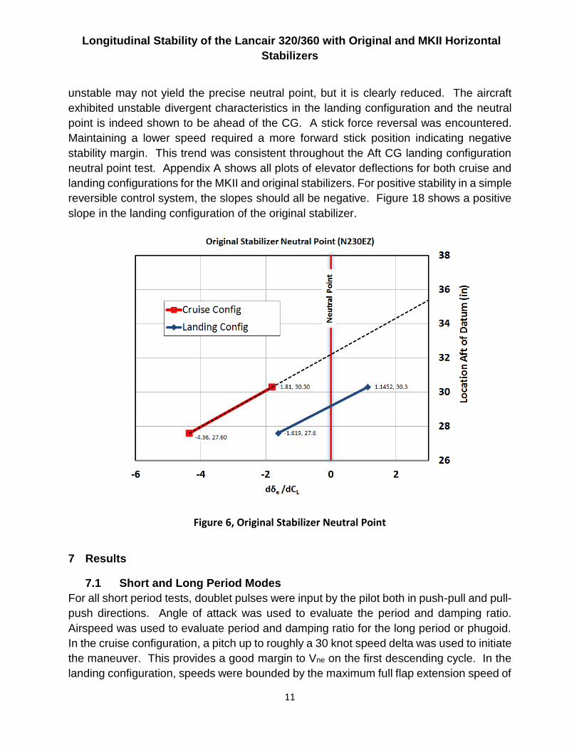
unstable may not yield the precise neutral point, but it is clearly reduced. The aircraft
exhibited unstable divergent characteristics in the landing configuration and the neutral
point is indeed shown to be ahead of the CG. A stick force reversal was encountered.
Maintaining a lower speed required a more forward stick position indicating negative
stability margin. This trend was consistent throughout the Aft CG landing configuration
neutral point test. Appendix A shows all plots of elevator deflections for both cruise and
landing configurations for the MKII and original stabilizers. For positive stability in a simple
reversible control system, the slopes should all be negative. Figure 18 shows a positive
slope in the landing configuration of the original stabilizer.
Figure 6, Original Stabilizer Neutral Point
7 Results
7.1 Short and Long Period Modes
For all short period tests, doublet pulses were input by the pilot both in push-pull and pull-
push directions. Angle of attack was used to evaluate the period and damping ratio.
Airspeed was used to evaluate period and damping ratio for the long period or phugoid.
In the cruise configuration, a pitch up to roughly a 30 knot speed delta was used to initiate
the maneuver. This provides a good margin to Vne on the first descending cycle. In the
landing configuration, speeds were bounded by the maximum full flap extension speed of
Longitudinal Stability of the Lancair 320/360 with Original and MKII Horizontal
Stabilizers
12
100 KIAS and stall speed. A pitch up to a 10-15 knot airspeed reduction was used to
initiate the long period mode in the landing configuration.
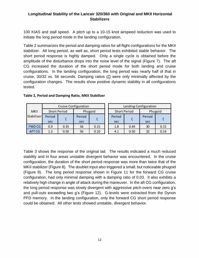
Table 2 summarizes the period and damping ratios for all flight configurations for the MKII
stabilizer. All long period, as well as, short period tests exhibited stable behavior. The
short period response is highly damped. Only a single cycle is obtained before the
amplitude of the disturbance drops into the noise level of the signal (Figure 7). The aft
CG increased the duration of the short period mode for both landing and cruise
configurations. In the landing configuration, the long period was nearly half of that in
cruise, 30/32 vs. 56 seconds. Damping ratios (ζ) were only minimally affected by the
configuration changes. The results show positive dynamic stability in all configurations
tested.
Table 2, Period and Damping Ratio, MKII Stabilizer
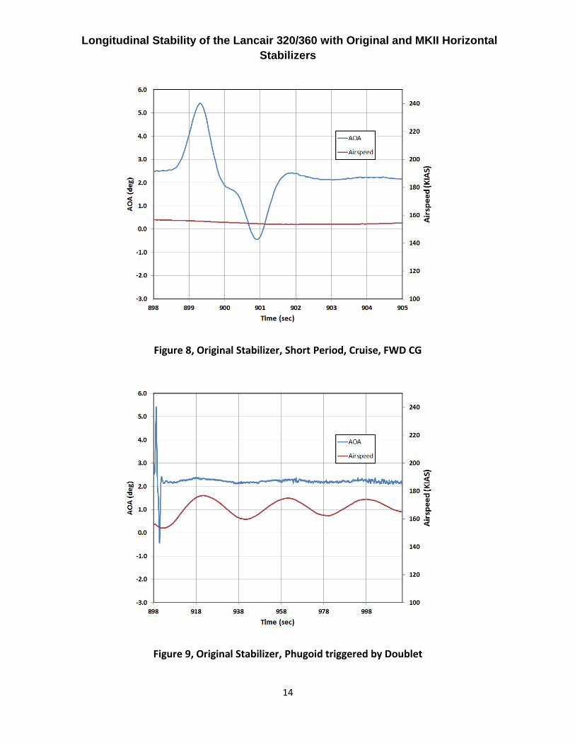
Table 3 shows the response of the original tail. The results indicated a much reduced
stability and in four areas unstable divergent behavior was encountered. In the cruise
configuration, the duration of the short period response was more than twice that of the
MKII stabilizer (Figure 8). The doublet input also triggered a small, but noticeable phugoid
(Figure 9). The long period response shown in Figure 11 for the forward CG cruise
configuration, had only minimal damping with a damping ratio of 0.03. It also exhibits a
relatively high change in angle of attack during the maneuver. In the aft CG configuration,
the long period response was slowly divergent with aggressive pitch-overs near zero g’s
and pull-outs exceeding two g’s (Figure 12). G-levels were extracted from the Dynon
PFD memory. In the landing configuration, only the forward CG short period response
could be obtained. All other tests showed unstable, divergent behavior.
Period Period Period Period
sec sec sec sec
FWD CG 0.9 0.35 56 0.15 1.8 0.44 30 0.15
AFT CG 1.3 0.50 56 0.10 4.1 0.50 32 0.14
MKII
Stabilizer
Landing Configuration
Short Period Phugoid
ζ ζ
Cruise Configuration
Short Period Phugoid
ζ ζ

Longitudinal Stability of the Lancair 320/360 with Original and MKII Horizontal
Stabilizers
13
Table 3, Period and Damping Ratio, Original Stabilizer
Figure 7, MKII Stabilizer, Short Period, Cruise, FWD CG
Period Period Period Period
sec sec sec sec
FWD CG 2.0 0.57 33 0.03 4.0 0.37
AFT CG 3.0 0.50 divergent divergent
divergent
divergent
Original
Stabilizer
Cruise Configuration Landing Configuration
Short Period Phugoid Short Period Phugoid
ζ ζ ζ ζ
Longitudinal Stability of the Lancair 320/360 with Original and MKII Horizontal
Stabilizers
14
Figure 8, Original Stabilizer, Short Period, Cruise, FWD CG
Figure 9, Original Stabilizer, Phugoid triggered by Doublet

Longitudinal Stability of the Lancair 320/360 with Original and MKII Horizontal
Stabilizers
15
Figure 10, MKII Stabilizer, Phugoid, Cruise, FWD CG
Figure 11, Original Stabilizer, Phugoid, Cruise, FWD CG
150
160
170
180
190
200
210
-2.0
-1.5
-1.0
-0.5
0.0
0.5
1.0
1.5
2.0
715 765 815 865 915
Air
spe
ed
(K
IAS)
AO
A (
de
g)
Time (sec)
AOA
Airspeed

Longitudinal Stability of the Lancair 320/360 with Original and MKII Horizontal
Stabilizers
16
Figure 12, Original Stabilizer, Phugoid, Cruise, AFT CG
7.2 Stick Force Gradients
The stick force gradient is obtained by applying a given stick force to the trimmed aircraft.
A stable aircraft will settle into a new equilibrium of speed, angle of attack and elevator
deflection. Table 4 summarizes the results in cruise.
Table 4, Stick Force Gradients, Cruise
Figure 13 shows the stick force gradients for the cruise and landing configurations for the
MKII stabilizer. In the cruise condition, the curves are nearly linear over the speed range
tested. The slope is negative for all cases indicating proper feedback. At low speeds,
reduced hinge moments result in greater control surface deflection. Figure 15 shows the
CG kts/lb CG kts/lb
Aft CG 30.3"* 29.5 33.4" 40.1
FWD CG 27.6" 25.9 28.9" 21.7
* 30.3" is the published aft CG limit
Speed Stability
Original Stabilizer MKII Stabilizer

Longitudinal Stability of the Lancair 320/360 with Original and MKII Horizontal
Stabilizers
17
corresponding angle of attack for a given stick force. All curves are smooth and
continuous providing good feedback.
The original tail produced a continuous shallow negative slope in the forward CG
configuration (Figure 14). In the aft CG configuration, however, the slope becomes nearly
vertical at low speed (higher AoA) indicating nearly neutral behavior. In the landing
configuration, both forward and aft CG conditions produced divergent behavior. No
restoring force was generated to counter the stick input force and thus no data is
presented for these two cases.
In the cruise configuration, the stick force gradient for the original stabilizer exhibited a
dramatic reduction in hinge moment at low airspeed. Figure 14 and Figure 16 show a
sharp increase in angle of attack and elevator deflection at the higher stick force input
near two pounds.
In the landing configuration, once trimmed for 90 KIAS, the application of any stick force
resulted in divergent behavior. This is consistent with the results obtained in long and
short period testing.
Figure 13, MKII Stabilizer Elevator Deflection with Stick Force
-7
-6
-5
-4
-3
-2
-1
0
1
2
-1.5 -1.0 -0.5 0.0 0.5 1.0 1.5 2.0
Elev
ato
r D
efle
ctio
n (
de
g), T
E D
N =
Po
s
Stick Force (lb), pull = pos
FWD-Landing Config
FWD-Cruise Config
AFT-Lndg Config
AFT-Cruise Config

Longitudinal Stability of the Lancair 320/360 with Original and MKII Horizontal
Stabilizers
18
Figure 14, Original Stabilizer, Elevator Deflection with Stick Force
Figure 15, MKII Stabilizer, Angle of Attack Sensitivity to Stick Force

Longitudinal Stability of the Lancair 320/360 with Original and MKII Horizontal
Stabilizers
19
Figure 16, Original Stabilizer, Angle of Attack Sensitivity to Stick Force
7.3 Handling Qualities
Experimental aircraft are not bound by FAA regulation in terms of stability and handling
qualities. It is useful, however, to review a few guidelines outlined in FAR 23.175
applicable to the results obtained during testing. FAR 23.175 is presented in its entirety
in Appendix B.
Design guidelines call for stable and predictable behavior in all phases of flight,
specifically within specified ranges of various trimmed flight conditions. The stick force
gradient must always be stable and upon relaxing of stick forces, the aircraft is to return
to its originally trimmed speed within a margin to allow for friction in the control system.
The MKII stabilizer meets these design guidelines. The original tail falls short in the
landing configuration. Specifically, the aircraft diverged once disturbed from its trim
condition instead of returning to the trim speed.
Stick force gradients are very shallow for both stabilizers. The FAA is rather hands-off in
setting quantitative standards for acceptable pitch sensitivity of GA aircraft. From FAR-
23: “any substantial speed change results in a stick force clearly perceptible to the pilot.” This
leaves room for interpretation, but it also provides the freedom to increase or reduce stick
forces according to the mission at hand.

Longitudinal Stability of the Lancair 320/360 with Original and MKII Horizontal
Stabilizers
20
8 Further Study
8.1 Trim system
The spring bias trim system used with the original stabilizer design may be aggravating
the stick free instability as the aircraft moves farther from trim speed. The rapid change
in hinge moments observed at speed less than 100 KIAS may be adversely combining
with fixed trim forces from the spring system. A few aircraft with the original stabilizer
have been modified with electrically driven trim tabs. Re-testing points that showed
divergent behavior on such a modified aircraft may provide insight into the contribution, if
any, of the trim system.
8.2 Strakes
The lift curve slope is dramatically reduced by the low aspect ratio of the original horizontal
stabilizer. The use of strakes may improve its effectiveness at lower air speeds and
higher angles of attack where instabilities were observed.
9 Conclusion
While both stabilizers have light stick forces, the flight characteristics produced by the
original and MKII stabilizers were found to be markedly different. The MKII stabilizer
exhibited stable behavior throughout the flight envelope in all configurations and CG
positions. Stick force feedback and stability followed criteria generally expected in good
aircraft design.
The original stabilizer showed instabilities and divergent behavior, most notably in slower
regions of the flight envelope. These characteristics require more vigilance and active
input by the pilot. Stick force reversals eliminate the typically expected force feedback to
the pilot. This necessitates use of flight instruments and other visual cues to determine
the proper control inputs. The instabilities are more pronounced at the aft CG limit.
The MKII stabilizer greatly increases the usable CG range of the aircraft. This permits a
significantly broader range of loading conditions.
10 Acknowledgements
I would like to extend my gratitude to Dan Meyer who volunteered the use of his Lancair
320 for this testing of the original stabilizer. Dan offered his assistance in instrumenting
the aircraft and also served as test pilot for all flights in N230EZ.

Longitudinal Stability of the Lancair 320/360 with Original and MKII Horizontal
Stabilizers
21
Works Cited
Somers, D. M. (1981). Design and Experimental Results for a Flapped Natural-Laminar-Flow Airfoil for
General Aviation Applications. NASA Technical Paper 1865.
Zavatson, C. J. (2007). Cooling Drag. Sport Aviation.
Zavatson, C. J. (2013). Experimental Evaluation of Cruise Flap Deflection on Total Aircraft Drag using the
NLF(1)-0215F.
Zavatson, C. J. (2013). Longitudinal Static Stability of the Lancair 360.

Longitudinal Stability of the Lancair 320/360 with Original and MKII Horizontal
Stabilizers
22
Appendix A Neutral Point Determination
Figure 17, Original Stabilizer Neutral Point Testing in Cruise Configuration
Figure 18, Original Stabilizer Neutral Point Testing in Landing Configuration
The neutral point can be determined experimentally with minimal instrumentation. For a
given trimmed flight condition and CG location there is a nearly linear relationship
between change in elevator position and change in lift coefficient. This relationship can
be exploited to find the neutral point in flight.
The process involves conducting at least two flight tests with the aircraft loaded to two
different CG positions, preferably near both ends of the envelope. During each test flight
the aircraft is trimmed for hands-free level flight. Then, without re-trimming, the aircraft is
manually held off trim speed long enough to capture steady state data for airspeed and
elevator position. The altitude must remain in a reasonable band for each test point. A
1,000’ window is sufficient. It is convenient to alternate one point above the trim speed
and one point below to keep the data points at nearly the same altitude.
Longitudinal Stability of the Lancair 320/360 with Original and MKII Horizontal
Stabilizers
23
Appendix B FAR Part 23.175
Sec. 23.175 Demonstration of static longitudinal stability.
Static longitudinal stability must be shown as follows:
(a) Climb. The stick force curve must have a stable slope at speeds between 85 and 115
percent of the trim speed, with--
(1) Flaps retracted;
(2) Landing gear retracted;
(3) Maximum continuous power; and
(4) The airplane trimmed at the speed used in determining the climb performance required
by Sec. 23.69(a).
(b) Cruise. With flaps and landing gear retracted and the airplane in trim with power for
level flight at representative cruising speeds at high and low altitudes, including speeds
up to VNO or VMO/MMO, as appropriate, except that the speed need not exceed VH--
(1) For normal, utility, and acrobatic category airplanes, the stick force curve must have
a stable slope at all speeds within a range that is the greater of 15 percent of the trim
speed plus the resulting free return speed range, or 40 knots plus the resulting free return
speed range, above and below the trim speed, except that the slope need not be stable-
-
(i) At speeds less than 1.3 VS1; or
(ii) For airplanes with VNE established under Sec. 23.1505(a), at speeds greater than
VNE; or
(iii) For airplanes with VMO/MMO established under Sec. 23.1505(c), at speeds greater
than VFC/MFC.
(2) For commuter category airplanes, the stick force curve must have a stable slope at all
speeds within a range of 50 knots plus the resulting free return speed range, above and
below the trim speed, except that the slope need not be stable--
(i) At speeds less than 1.4 VS1; or
(ii) At speeds greater than VFC/MFC; or
(iii) At speeds that require a stick force greater than 50 pounds.

Longitudinal Stability of the Lancair 320/360 with Original and MKII Horizontal
Stabilizers
24
(c) Landing. The stick force curve must have a stable slope at speeds between 1.1 VS1
and 1.8 VS1 with--
(1) Flaps in the landing position;
(2) Landing gear extended; and
(3) The airplane trimmed at--
(i) VREF, or the minimum trim speed if higher, with power off; and
(ii) VREF with enough power to maintain a 3 degree angle of descent.