Embed Size (px)
Citation preview
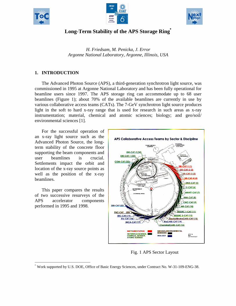
Long-Term Stability of the APS Storage Ring∗
H. Friedsam, M. Penicka, J. ErrorArgonne National Laboratory, Argonne, Illinois, USA
1. INTRODUCTION
The Advanced Photon Source (APS), a third-generation synchrotron light source, wascommissioned in 1995 at Argonne National Laboratory and has been fully operational forbeamline users since 1997. The APS storage ring can accommodate up to 68 userbeamlines (Figure 1); about 70% of the available beamlines are currently in use byvarious collaborative access teams (CATs). The 7-GeV synchrotron light source produceslight in the soft to hard x-ray range that is used for research in such areas as x-rayinstrumentation; material, chemical and atomic sciences; biology; and geo/soil/environmental sciences [1].
∗ Work supported by U.S. DOE, Office of Basic Energy Sciences, under Contract No. W-31-109-ENG-38.
For the successful operation ofan x-ray light source such as theAdvanced Photon Source, the long-term stability of the concrete floorsupporting the beam components anduser beamlines is crucial.Settlements impact the orbit andlocation of the x-ray source points aswell as the position of the x-raybeamlines.
This paper compares the resultsof two successive resurveys of theAPS accelerator componentsperformed in 1995 and 1998.
Fig. 1 APS Sector Layout

2. ALIGNMENT TOLERANCES
During construction of the APS the Survey and Alignment Group placed theaccelerator components within tight absolute and relative tolerances derived from latticesimulations performed by the APS Accelerator Physics Group. The tolerances for thesecomponents, reported in detail in previous IWAA proceedings such as IWAA93 [2], aresummarized below.
2.1 Absolute positioning tolerances
The global placement tolerance requires the positioning of each beam component, inthe APS reference frame, to within a vertical and horizontal envelope of ±5mm of theideal position. The roll of all multipoles and dipoles has to be set to within ±0.5mrad.
2.2 Relative positioning tolerances
The relative alignment between beam elements depends on the type of componentand its location in the accelerator system. The most stringent requirements have to beachieved for the positioning of the storage ring multipoles. According to the designspecifications for those magnets [3], a relative alignment tolerance of ±0.15mm isrequired in both the vertical and horizontal directions.
3. ALIGNMENT RESULTS
After the completion of the storage ring girder alignment in early 1995, the positionsof all multipoles and dipoles were measured once more using laser trackers [4]. In orderto obtain the connection between individual tracker setups, additional temporary controlpoints were installed and measured. The data, including elevation information, wereanalyzed using a bundle adjustment routine developed at Stanford Linear AcceleratorCenter (SLAC). The differences between the resulting magnet positions from the bundleadjustment and the ideal locations were then subjected to a smooth curve fitting operationto obtain an estimate for the achieved relative alignment [5].
The results of this smoothing process are shown in Figures 2 through 5 for thetransverse and vertical deviations, respectively. One can see that the smooth curve fits thedata points, which represent the deviations between the measured and ideal locations ofeach magnet fiducial, very closely. Each histogram shows the distribution of the pointoffsets from the fitted curve sorted in 0.1mm wide bins. These indicate that thepositioning of the components is well within the required placement tolerances. Thestandard deviation of the offsets from the point location to the smooth curve is ±0.09mmfor the transverse position and ±0.07mm for the vertical position, respectively. The meanis zero in both cases. In addition, each histogram contains the Gaussian distribution forthe achieved standard deviation as a solid line and the expected distribution using thegiven tolerance limits as a dashed line. All data points are within the 2σ range of±0.3mm.
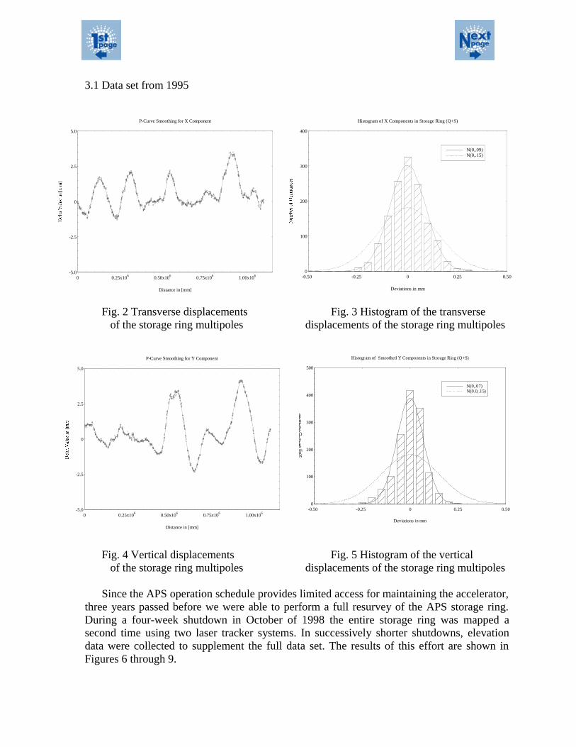
3.1 Data set from 1995
Fig. 2 Transverse displacements Fig. 3 Histogram of the transverseof the storage ring multipoles displacements of the storage ring multipoles
Fig. 4 Vertical displacements Fig. 5 Histogram of the verticalof the storage ring multipoles displacements of the storage ring multipoles
Since the APS operation schedule provides limited access for maintaining the accelerator,three years passed before we were able to perform a full resurvey of the APS storage ring.During a four-week shutdown in October of 1998 the entire storage ring was mapped asecond time using two laser tracker systems. In successively shorter shutdowns, elevationdata were collected to supplement the full data set. The results of this effort are shown inFigures 6 through 9.
-5.0
-2.5
0
2.5
5.0
0 0.25x10⁶ 0.50x10⁶ 0.75x10⁶ 1.00x10⁶
Distance in [mm]
P-Curve Smoothing for X Component
0
100
200
300
400
-0.50 -0.25 0 0.25 0.50
N(0,.09)N(0,.15)
Deviations in mm
Histogram of X Components in Storage Ring (Q+S)
-5.0
-2.5
0
2.5
5.0
0 0.25x10⁶ 0.50x10⁶ 0.75x10⁶ 1.00x10⁶
Distance in [mm]
P-Curve Smoothing for Y Component
0
100
200
300
400
500
-0.50 -0.25 0 0.25 0.50
N(0,.07)N(0.0,.15)
Deviations in mm
NumberofOccurances
Histogram of Smoothed Y Components in Storage Ring (Q+S)
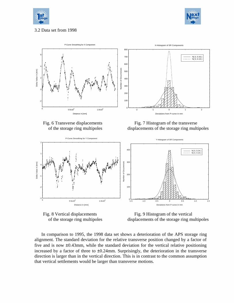
3.2 Data set from 1998
-2
0
2
4
6
0 0.5x10⁶
1.0x10⁶
Distance in [mm]
De
lta V
alu
e in
[mm
]
P-Curve Smoothing for X Component
0
100
200
300
400
500
600
700
800
-2 -1 0 1 2
N( 0, 0.43 )N( 0, 0.15 )
Deviations from P-curve in mm
Nu
mbe
r o
f O
ccu
rre
nce
s
X-Histogram of SR Components
Fig. 6 Transverse displacements Fig. 7 Histogram of the transverseof the storage ring multipoles displacements of the storage ring multipoles
-3
-2
-1
0
1
2
0 0.5x10⁶
1.0x10⁶
Distance in [mm]
De
lta V
alu
e in
[m
m]
P-Curve Smoothing for Y Component
0
100
200
300
400
-1.5 -1.0 -0.5 0 0.5 1.0 1.5
N( 0, 0.24 )N( 0, 0.15 )
Deviations from P-curve in mm
Nu
mb
er
of
Occ
urr
en
ces
Y-Histogram of SR Components
Fig. 8 Vertical displacements Fig. 9 Histogram of the verticalof the storage ring multipoles displacements of the storage ring multipoles
In comparison to 1995, the 1998 data set shows a deterioration of the APS storage ringalignment. The standard deviation for the relative transverse position changed by a factor offive and is now ±0.43mm, while the standard deviation for the vertical relative positioningincreased by a factor of three to ±0.24mm. Surprisingly, the deterioration in the transversedirection is larger than in the vertical direction. This is in contrast to the common assumptionthat vertical settlements would be larger than transverse motions.
It is apparent that the 1998 data set no longer meets the initial tolerancespecifications, and a large fraction of the components falls outside the 2σ limit. However,the operation of the accelerator so far has not suffered from this fact. Unfortunately, adirect comparison of the vital accelerator data between the 1995 and 1998 survey datasets is not possible due to the fact that many of the machine measurement tools were notavailable during the initial 1995 commissioning phase.
Since 1995 only two local realignments were necessary. The first was an experimentto evaluate the effects of a vertical girder realignment in selected sectors of the storagering on beam operation parameters. The two sectors with the largest settlement wererealigned using a smooth-curve-fitting routine to eliminate the largest settlementdistortion. Adjustments up to 2mm were required for this. However, the impact on theperformance of the APS storage ring was negligible and hardly detectable with themeasurement tools at hand [6].
The beam path in the area of the deformation was smooth before the realignment tookplace. This supports the choice of using a monolithic storage ring floor for construction.The floor does not permit any expansion joints that would cause discontinuities betweenadjacent slabs. Instead, a local deformation is being distributed over a large area,producing a smooth deformation [7].
The second modification required the artificial transverse distortion of two sectors ofthe APS storage ring for the purpose of implementing a new feedback system [8]. Afterthe new lattice was realized, no major orbit distortions outside that region were measured.This indicates that as long as the particle beam follows a smooth beam path, theperformance of the system will hardly change. However, it is very important to check forlarge steps between adjacent multipoles that have an impact on the beam emittance.
Comparing the two data sets one can see that the 1998 data contain string-likefeatures that can only be explained by the displacement of an entire girder, indicating thepossibility that the intra-girder alignment is more stable over time than the inter-girderalignment. In order to prove this hypothesis, the 1995 and 1998 data were each split intotwo parts. The first part analyzes the steps between adjacent multipoles on straightgirders, while the second part examines the transverse and vertical steps between adjacentgirders. Steps are simply calculated as transverse and vertical differences betweenadjacent components.
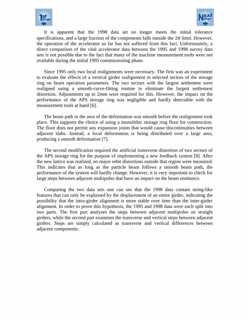
3.3 Intra-Girder Alignment Comparison
The results of this process for the intra-girder alignment are shown in Figures 10through 13 for the transverse and vertical steps of the 1995 and 1998 data. Eachhistogram shows the steps sorted in bins 0.1mm wide. One can see that the standarddeviation between these two data sets hardly changes and that most of the componentsare within the 2σ limit, indicating that the alignment of the magnets on a girder is fairlystable over time as stated in the hypothesis. The standard deviation in the transverse casechanges from ±0.07mm to ±0.10mm, while in the vertical case it changes from ±0.05mmto ±0.10mm.
0
50
100
150
200
250
-2.0 -1.5 -1.0 -0.5 0 0.5 1.0 1.5 2.0
N (0, 0.07)
Horizontal Step in [mm] measured w/r to P-curve
Nu
mbe
r o
f O
ccu
rren
ces
Histogram of Horizontal Steps between Magnets on Straight Girders (April'95)
0
50
100
150
200
250
-2.0 -1.5 -1.0 -0.5 0 0.5 1.0 1.5 2.0
N (0, 0.10)
Horizontal step in [mm] measured w/r to P-curve
Nu
mbe
r o
f O
ccu
rren
ces
Histogram of Horizontal Steps between Magnets on Straight Girders (April'99)
Fig 10 Transverse magnet step data, 1995 Fig 11 Transverse magnet step data, 1998
0
100
200
300
-2.0 -1.5 -1.0 -0.5 0 0.5 1.0 1.5 2.0
N (0, 0.05)
Vertical Step in [mm] measured w/r to P-curve
Num
ber
of
Occ
urre
nce
s
Histogram of Vertical Steps between Magnets on Straight Girders (April'95)
0
50
100
150
200
250
-2.0 -1.5 -1.0 -0.5 0 0.5 1.0 1.5 2.0
N (0, 0.10)
Vertical step in mm measured w/r to P-curve
Nu
mb
er o
f Occ
urr
enc
es
Histogram of Vertical Steps between Magnets on Straight Girders (April'99)
Fig 12 Vertical magnet step data, 1995 Fig 13 Vertical magnet step data, 1998
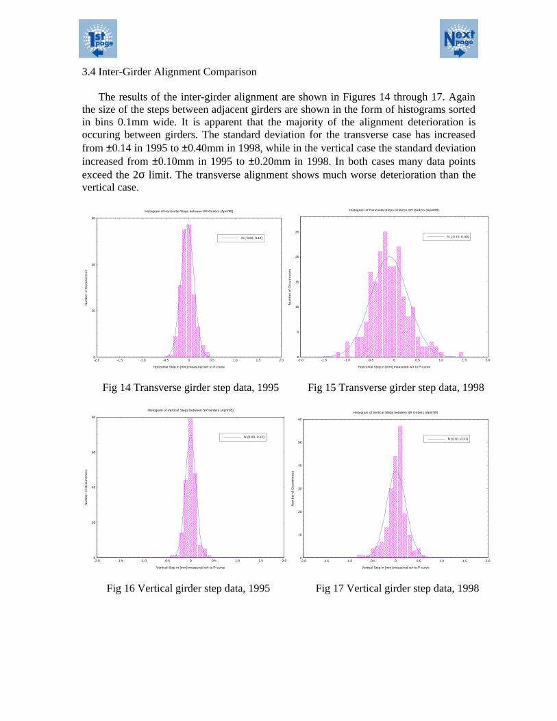
3.4 Inter-Girder Alignment Comparison
The results of the inter-girder alignment are shown in Figures 14 through 17. Againthe size of the steps between adjacent girders are shown in the form of histograms sortedin bins 0.1mm wide. It is apparent that the majority of the alignment deterioration isoccuring between girders. The standard deviation for the transverse case has increasedfrom ±0.14 in 1995 to ±0.40mm in 1998, while in the vertical case the standard deviationincreased from ±0.10mm in 1995 to ±0.20mm in 1998. In both cases many data pointsexceed the 2σ limit. The transverse alignment shows much worse deterioration than thevertical case.
0
20
40
60
-2.0 -1.5 -1.0 -0.5 0 0.5 1.0 1.5 2.0
N (-0.03, 0.14)
Horizontal Step in [mm] measured w/r to P-curve
Nu
mb
er o
f Occ
urre
nce
s
Histogram of Horizontal Steps between SR Girders (April'95)
0
5
10
15
20
25
-2.0 -1.5 -1.0 -0.5 0 0.5 1.0 1.5 2.0
N (-0.10, 0.40)
Horizontal Step in [mm] measured w/r to P-curve
Num
be
r of
Occ
urr
enc
es
Histogram of Horizontal Steps between SR Girders (April'99)
Fig 14 Transverse girder step data, 1995 Fig 15 Transverse girder step data, 1998
0
20
40
60
80
-2.0 -1.5 -1.0 -0.5 0 0.5 1.0 1.5 2.0
N (0.00, 0.11)
Vertical Step in [mm] measured w/r to P-curve
Nu
mbe
r o
f O
ccu
rren
ces
Histogram of Vertical Steps between SR Girders (April'95)
0
10
20
30
40
50
60
-2.0 -1.5 -1.0 -0.5 0 0.5 1.0 1.5 2.0
N (0.01, 0.21)
Vertical Step in [mm] measured w/r to P-curve
Num
ber
of
Occ
urre
nce
s
Histogram of Vertical Steps between SR Girders (April'99)
Fig 16 Vertical girder step data, 1995 Fig 17 Vertical girder step data, 1998

4. SUMMARY
As one would expect, the alignment of the APS storage ring is deteriorating overtime. By separating the data into intra- and inter-girder subsets, we were able show thatthe main source for the alignment deterioration can be attributed to changes in the relativegirder alignment. The driving force for these misplacements is still under investigation.Some possible causes for the transverse motion have been suggested:
1. Temperature fluctuations in the storage ring could cause girder creep over time.2. The girders are virtually floating on vibration damping pads [9]. Changes in the
viscosity of these pads could be the cause for the transverse motion.3. Floor settlements, transverse to the beam direction, induce roll in the girders that
is seen as transverse motion.
Our main focus has always been directed towards large changes along the verticaldirection. This is still a proper assumption. However, settlements affect the string ofgirder supports not only along the beamline but also perpendicular to that line. This kindof settlement will affect the girder roll and therefore the transverse position. Due to theunfavorable long lever arm from the floor support to the beam height, any smalltransverse settlement is amplified and produces a large transverse motion. As a result,future synchrotron light sources would be best served to minimize the distance from thefloor to the beam height. This type of construction has the additional advantage ofreducing vibration effects, which may render vibration-damping pads unnecessary.
We are currently in the process of mapping the APS storage ring a third time in orderto follow the trend of distortions seen so far. We have started to take roll measurementsin the areas showing the largest steps in order to verify the assumption made in paragraphthree of the above list of possible causes. However, based on this small sample, theresults are inconclusive.
The roll measurements are taken using special roll fixtures. In hindsight it would bebetter to have at least three fiducial points per magnet in order to track these componentsas three-dimensional rigid bodies. This would increase the time for fiducialization butwould make the mapping process, especially when using laser tracker systems, muchfaster. This feature is especially valuable when considering the short time periods theaccelerator components are accessible for survey.
Furthermore it would have been beneficial if all multipoles had been located on onegirder, leaving the dipole on its own support system. Dipoles usually have a more relaxedposition tolerance compared to the multipole requirements. However, dipole roll settingsare usually more stringent. A separation of these two magnet types would have betterfacilitate these different requirements.
5. ACKNOWLEDGMENT
I would like to acknowledge all APS survey and alignment personnel for their effortsin collecting the data and handling the analysis of these large data sets as well as CathyEyberger for her helpful suggestions while editing and refining this paper.
6. REFERENCES
[1] Advanced Photon Source RESEARCH, Number 2, June 1999 (ANL/APS/TB-36).
[2] H. Friedsam, The Alignment of the Advanced Photon Source at Argonne National Laboratory, Proceedings of theThird International Workshop on Accelerator Alignment, Annecy, France, September 1993, pp. I/1 - I/8.
[3] 7-GeV Advanced Photon Source Conceptual Design Report, Argonne National Laboratory, ANL-87-15, 1987.
[4] H. Friedsam, A New Accelerator Alignment Concept using Laser Trackers, Proceedings of the Fourth EuropeanParticle Accelerator Conference, London, June 1994, pp. 2567 - 2570.
[5] H. Friedsam, M. Penicka, S. Zhao, Beamline Smoothing of the Advanced Photon Source, Proceedings of the 1995Particle Accelerator Conference, Dallas, USA, March 1995, pp. 2084 - 2086.
[6] E. Lessner, E. Crosbie, S. Milton, Effects of the Vertical Girder Realignment in the Argonne APS Storage Ring,Proceedings of the 1999 Particle Accelerator Conference, New York, USA, 1999 (to be published).
[7] H. Friedsam, M. Penicka, J. Error, Status Report on the Long-Term Stability of the Advanced Photon Source,Proceedings of the Fifth International Workshop on Accelerator Alignment, Argonne, Illinois, October 1997(CD-ROM).
[8] G. Decker, O. Singh, H. Friedsam, J. Jones, M. Ramanathan, D. Shu, Reduction of X-BPM Systematic Errors byModification of Lattice in the APS Storage Ring, Proceedings of the 1999 Particle Accelerator Conference, NewYork, USA, 1999 (to be published).
[9] D. Mangra, S. Sharma, J. Jendrzejczyk, Passive vibration damping of the APS machine components, Proceedingsof the Conference on Synchrotron Radiation Instrumentation ‘95, Argonne, Illinois, October 1995, Rev. Sci.Instrum., 67 (9), September 1996 (CD-ROM).