Embed Size (px)
Citation preview
U.S. Department of the InteriorU.S. Geological Survey
Long-Term Ground-Water Monitoring Program and Performance-Evaluation Plan for the Extraction System at the Former Nike MissileBattery Site, Aberdeen Proving Ground, Maryland
Open-File Report 00-208
In cooperation with
U.S. Army Garrison, Aberdeen Proving GroundEnvironmental Conservation And Restoration DivisionAberdeen Proving Ground, Maryland
The contents of this report have been approved for public release and unlimited distribution by the U.S. Army--distribution number 2958-A-4
Baltimore Maryland2000
By Michael P. Senus and Frederick J. Tenbus
U.S. DEPARTMENT OF THE INTERIORBRUCE BABBITT, Secretary
U.S. Geological SurveyCharles G. Groat, Director
The use of trade, product, or firm names in this report is fordescriptive purposes only and does not imply endorsement by the U.S. Geological Survey.
For additional information contact:
District ChiefU.S. Geological Survey, WRD8987 Yellow Brick RoadBaltimore, Maryland 21237
Copies of this report can be purchased from:
U.S. Geological SurveyBranch of Information ServicesBox 25286Denver, CO 80225-0286

CONTENTS
Abstract ..................................................................................................................................................................................1Introduction ............................................................................................................................................................................1
Purpose and scope .........................................................................................................................................................4Site history.....................................................................................................................................................................4Previous work .......................................................................................................................................................…… 4Description of study area ...............................................................................................................................................4
Geologic setting ....................................................................................................................................................4Hydrogeologic setting ...........................................................................................................................................5
Ground water................................................................................................................................................5Surface water................................................................................................................................................5Water use ......................................................................................................................................................5
Climate and precipitation ......................................................................................................................................5Extent of contamination ........................................................................................................................................5Environmental receptors .......................................................................................................................................5
Remedial Action at the Nike Site ..................................................................................................................................5Permit and monitoring requirements .............................................................................................................................7Acknowledgments .........................................................................................................................................................7
Long-term monitoring program for the Nike Site ..................................................................................................................8Long-term monitoring objectives ..................................................................................................................................8Frequency and location of sampling..............................................................................................................................8Quality-assurance and quality-control procedures ......................................................................................................11Measurement of water levels .......................................................................................................................................11Sampling for trichloroethene and diffusion sampling .................................................................................................11Ground-water-flow modeling ......................................................................................................................................12
Performance-evaluation plan for the Nike Site ground-water extraction system ................................................................12Data-Quality Objectives ..............................................................................................................................................12Tasks ............................................................................................................................................................................15
Ground-water extraction system optimization and evaluation ...........................................................................15Treatment system sampling and analysis............................................................................................................15Description of decision points ............................................................................................................................16Decision matrix for optimizing extraction system..............................................................................................16Decision matrix for determining system shutdown ............................................................................................16
Summary ..............................................................................................................................................................................19Selected references ...............................................................................................................................................................20
FIGURES
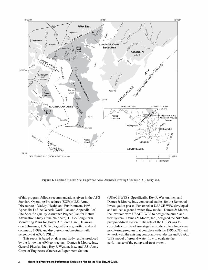
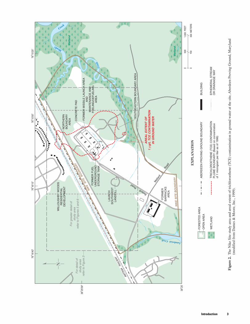
1. Map showing the location of Nike Site, Edgewood Area, Aberdeen Proving Ground (APG), Maryland....................22. Map showing the Nike Site study area and areal extent of trichloroethene (TCE)
contamination in ground water .............................................................................................................................33. Map showing water-level altitudes in the surficial aquifer at the Nike Site, October 1996..........................................64. Photograph showing view looking east at Nike Site ground-water treatment system ..................................................75. Map showing sampling points for long-term monitoring at the Nike Site ....................................................................96. Map showing location of Nike Site extraction wells...................................................................................................147. Decision tree to determine modifications to treatment system....................................................................................178. Decision tree to determine treatment system shutdown ..............................................................................................18
iii
TABLES
1. Well construction details and trichloroethene (TCE) concentrations for monitoring wells at theFormer Nike Site, Aberdeen Proving Ground, Maryland ..................................................................................10
2. Description of extraction well construction at the Former Nike Site, Aberdeen Proving Ground, Maryland ........13
CONVERSION FACTORS, ABBREVIATIONS, AND VERTICAL DATUM_____________________________________________________________________________________________________________________________________
Multiply By To obtain
_____________________________________________________________________________________________________________________________________inch (in.) 2.54 centimeterinch (in.) 25,400 micrometer
foot (ft) 0.3048 meterfoot per day (ft/d) 0.3048 meter per day
gallons per minute (gpm) 0.00006309 cubic meters per secondmile (mi) 1.609 kilometer
_____________________________________________________________________________________________________________________________________
Vertical datum: In this report, “sea level” refers to the national Geodetic Vertical Datum of 1929—a geodetic datum derived from a general adjustment of the first order level nets of the United States and Canada, formerly called Sea Level Datum of 1929.
Other abbreviated units of measure: Water temperature, chemical concentration, and other chemical and physical properties of constituents are given in metric units. Water temperature in degrees Celsius (ºC) can be converted to degrees Fahrenheit (ºF) by use of the following equation:
oF = 1.8 x (oC) + 32
Chemical concentration in water is expressed in milligrams per liter (mg/L), and in micrograms per liter (µg/L).
iv
ACRONYMS AND ABBREVIATIONS
APG Aberdeen Proving Groundbgs below ground surfaceCOC contaminant of concernCERCLA Comprehensive Environmental Response, Compensation, and Liability ActDQO Data-Quality Objectives
DSHE Directorate of Safety, Health, and EnvironmentECRD Environmental Conservation and Restoration DivisionEW extraction wellFS Feasibility StudyGAC granular activated carbon
GMS Groundwater Modeling Systemgpm gallons per minuteIR Installation RestorationLTM Long-Term MonitoringMCL Maximum Contaminant Level
MDE Maryland Department of the EnvironmentNPDES National Pollution Discharge Elimination SystemQA/QC Quality Assurance/Quality ControlQAPP Quality Assurance Project PlanQC Quality Control
RAB Restoration Advisory BoardRCRA Resource Conservation and Recovery ActRI Remedial InvestigationRI/FS Remedial Investigation/Feasibility StudyROD Record of Decision
SOP Standard Operating ProcedureTCE Trichloroetheneµg/L micrograms per literUSACE U.S. Army Corps of EngineersUSEPA U.S. Environmental Protection Agency
USGS U.S. Geological SurveyUST underground storage tankVOC Volatile Organic CompoundWES Waterways Experiment Station
v

1Abstract
Long-Term Ground-Water Monitoring Program and Performance-Evaluation Plan for the Extraction System at the Former Nike Missile Battery Site, Aberdeen Proving Ground, Maryland
By Michael P. Senus and Frederick J. Tenbus
Abstract
This report presents a long-term ground-water monitoring program and ground-water extraction system performance monitoring and evaluation program developed by the U.S. Geological Survey during 1999–2000 in support of the remedial action conducted at the Former Nike Missile Battery Site (Nike Site), Edgewood Area, Aberdeen Proving Ground, Maryland. Concentra-tions of trichloroethene at the Nike Site ranged from below the Maximum Contaminant Level of 5 micrograms per liter to 299 micrograms per liter during the Remedial Investigation under the Comprehensive Environmental Response, Compensation, and Liability Act program. The long-term monitoring program utilizes six selected monitoring wells that surround a trichloroethene contaminant plume. These wells will be monitored for five years and then reviewed by Federal and State regulators to determine whether future monitoring will be required. The perform-ance assessment plan was formulated from existing data and interpretations provided by the Remedial Investigation/Feasibility Study process and the 100% Remedial Design of the extraction-treatment system. A performance evaluation of the Nike Site extraction system partially fulfills the remedial action requirement to monitor ground water as stipulated in the September 1996 Record of Decision. Eight extraction wells that can pump up to 60 gallons per minute will be closely monitored and evaluated to determine capture and treatment of the trichloroethene plume at the Nike Site. Water-level and water-quality data will be
reviewed and analyzed to determine program cost-effectiveness and on-site ground-water extraction system performance. Tools such as the U.S. Army Corps of Engineers Waterways Experiment Station ground-water-flow model can be used to help run the system efficiently while maintaining hydraulic control of the contaminant plume.
Introduction
In 1999, the U.S. Army instituted a ground-water remediation program for the Former Nike Missile Battery Site (Nike Site), Edgewood Area, Aberdeen Proving Ground (APG), Maryland (figs. 1 and 2) in accordance with its 1996 Record of Decision (ROD) (Dames & Moore, Inc., 1996) under the Comprehensive Environmental Response, Compensation, and Liability Act (CERCLA) program. The remedial action involves long-term monitoring (LTM) (Dames & Moore, Inc., 1996) and recovery of trichloro-ethene (TCE)-contaminated ground water at concentrations above 5 µg/L (micrograms per liter)1 (Dames & Moore, Inc., 1999) to prevent future off-site migration of the plume (fig. 2). A performance monitoring and evaluation program of the remedial action was formulated from existing data and interpretations from the Remedial Investigation (RI) (Dames & Moore, Inc., 1995a), Feasibility Study (FS) (Dames & Moore, Inc., 1995b), and the ground-water-treatment system design report (Dames & Moore, Inc, 1999).
In 1999, the U.S. Geological Survey (USGS) began a cooperative study with the Environmental Conservation and Restoration Division (ECRD) of the APG Directorate of Safety, Health, and Environment (DSHE) to prepare a plan to evaluate the performance of the pump-and-treat system as it pertains to the requirements of the ROD 2. The LTM part
1. The contaminant plume (fig. 2) is defined in the ROD as ground water with concentrations of TCE above 1 microgram per liter (Dames & Moore, Inc., 1996, p. 2–7) for purposes of discussing site contamination. Ground-water recovery and monitoring at and above concentrations of 5 µg/L TCE, however, are stipulated in the ROD.
2. For the purposes of this report, chemical analyses and ground-water elevation data for the Nike Site from the RI produced by Dames & Moore, Inc., (1995a, b) under the CERCLA program (Donald Green, ECRD, DSHE, APG, oral commun., 1999) will be used.
Monitoring Program and Performance-Evaluation Plan for the Nike Site, APG, Md.2
of this program follows recommendations given in the APG Standard Operating Procedures (SOPs) (U.S. Army Directorate of Safety, Health and Environment, 1995, Appendix J of the Generic Work Plan and Appendix I of Site-Specific Quality Assurance Project Plan for Natural Attenuation Study at the Nike Site), USGS Long-Term Monitoring Plans for Dover Air Force Base, Delaware (Kurt Hinaman, U.S. Geological Survey, written and oral commun., 1999), and discussions and meetings with personnel at APG’s DSHE.
This report is based on data and study results produced by the following APG contractors: Dames & Moore, Inc., General Physics, Inc., Roy F. Weston, Inc., and U.S. Army Corps of Engineers Waterways Experiment Station
(USACE WES). Specifically, Roy F. Weston, Inc., and Dames & Moore, Inc., conducted studies for the Remedial Investigation phase. Personnel at USACE WES developed and utilized a ground-water-flow model. Dames & Moore, Inc., worked with USACE WES to design the pump-and-treat system. Dames & Moore, Inc., designed the Nike Site pump-and-treat system. The role of the USGS was to consolidate results of investigative studies into a long-term monitoring program that complies with the 1996 ROD, and to work with the existing pump-and-treat design and USACE WES model of ground-water flow to evaluate the performance of the pump-and-treat system.
3Introduction
Monitoring Program and Performance-Evaluation Plan for the Nike Site, APG, Md.4
Purpose and ScopeThis report presents a long-term monitoring and
performance-evaluation program in support of the remedial action conducted at the Former Nike Missile Battery Site at APG. The performance monitoring and evaluation program presents site-specific details for a performance assessment of the extraction system in conjunction with LTM at the Nike Site. The system will be evaluated relative to its ability to remediate TCE from the surficial aquifer as stipulated in the ROD (Dames & Moore, Inc., 1996). This report also includes descriptions of the site, previous environmental sampling, and a discussion of the rationale for implement-ation of monitoring plans for TCE contamination at the Nike Site. Pursuant to CERCLA, the ground-water extraction system evaluation is in partial fulfillment of the remedial action requirement to monitor ground water as documented in the ROD (Dames & Moore, Inc., 1996).
The extraction system performance evaluation of this program follows recommendations and suggestions from discussions and meetings with personnel at APG’s DSHE, Dames & Moore, Inc., Roy F. Weston, Inc., and the U.S. Army Corps of Engineers WES. One of the objectives of this report was to develop a performance-evaluation plan that could be used at any time during the long-term monitoring program, and/or during the operation of the extraction system. It was designed so that APG DSHE (or its contractors) could easily review objectives and regulatory constraints at the Nike Site, and make appropriate changes (if necessary) in response to new hydrologic or geochemical data or changes in remedial, hydrologic, technical, or socioeconomic conditions.
The plan set forth in this report will assist in answering the following questions:
• What are the recommended methods for meeting the challenges of effective hydraulic containment of the plume?
• How can the design and operation of the pump-and-treat system be optimized and its performance measured?
Site HistoryAPG is a U.S. Army installation in Harford County,
Maryland, about 20 miles northeast of Baltimore (fig. 1). The Nike Site is within the boundaries of the Edgewood Area of APG, Lauderick Creek Area (fig. 1), and is managed by DSHE as a CERCLA site under the Installation Restoration (IR) Program. The Nike Site is regulated by the U.S. Environmental Protection Agency (USEPA), Region III and the Maryland Department of the Environment (MDE). From 1954 to 1973, this site was an active Nike-Ajax and Nike-Hercules missile-storage and launch-operations facility. The Nike surface-to-air weapon system was used to defend major populated areas, such as the City of Baltimore, during the years following World War II (U.S. Army Ordnance Missile Command, 1959). Ground-water contamination at the Nike Site is attributed to the storage, handling, and disposal of solvents and cleaning agents used
during operations and activities at Nike control and launching areas (Nemeth, 1989; Dames & Moore, Inc., 1996). In 1973, the Nike Missile Battery was decommis-sioned and many on-site structures were demolished. In 1993, all six missile vaults were sealed with concrete. In addition to abandonment of Nike Missile Battery facilities, there were CERCLA-related removal actions in the vicinity of the launch area between 1994 and 1995 (Dames & Moore, Inc., 1999). The Maryland U.S. Army National Guard currently uses the area for infantry training. Access to the site is restricted to authorized personnel.
Previous WorkPrevious investigations and information on the Nike Site
include required reports under the Resource Conservation and Recovery Act (RCRA) and CERCLA programs. Documents for the work performed under RCRA include the RCRA Facilities Assessment (Nemeth, 1989) and RCRA Facilities Investigation (Nemeth, 1990). Documentation of the CERCLA work can be found in the Preliminary Assessment/Site Investigation report (Dames & Moore, Inc., 1990), the RI report (Dames & Moore, Inc., 1995a), the FS report (Dames & Moore, Inc., 1995b), the ROD (Dames & Moore, Inc., 1996), the 100% Remedial Design (Dames & Moore, Inc., 1999), Nike Site Natural Attenuation Evaluation (Roy F. Weston, Inc., 1999, 2000b), and Nike Site Plume Migration Study (Roy F. Weston, Inc., 2000a). A ground-water-flow model of the site was constructed to support the remedial design (U.S. Army Corps of Engineers Waterways Experiment Station, 1998).
Description of Study AreaAPG is divided into multiple CERCLA-related “study
areas,” which are each comprised of one or more “clusters” that contain potential and known sources of contamination. The Nike Site is in Cluster 1 of the Lauderick Creek Study Area, in the northeast section of the Edgewood Area (fig. 2). The site is bordered to the west and north by APG’s boundary, the Amtrak railroad line, and residential areas (Willoughby Woods Residential Development). Wooded and marshy areas of Monks Creek border the site to the south and east. Six abandoned missile vaults, several buildings, open fields, a landfill, and a septic tank/subsurface sand filter bed system occupy the site (Dames & Moore, Inc., 1995a).
Geologic Setting The Edgewood Area of APG includes the Gunpowder Neck Peninsula in Harford County (fig. 1) and is located within the Atlantic Coastal Plain Physiographic Province. The Nike Site is underlain by unconsolidated sediments more than 300 ft (feet) thick (Owens, 1969). These sediments comprise interbedded strata of Late Cretaceous and Quaternary fluvial clay, silt, and sand with occasional gravel lenses. These sediments belong to the Patapsco Formation of the Potomac Group (Cretaceous), which is an interbedded sand and clay unit of fluvial origin, and to the Talbot Formation (Pleistocene), which contains fluvial, estuarine, and marginal marine deposits comprising sand, gravel, and silty clay (Owens, 1969). These sediments dip and thicken toward the
5Introduction
southeast (in the direction of the Chesapeake Bay). Paleozoic bedrock in the area consists of schist, gneiss, metagabbro, marble, and quartzite (Dames & Moore, Inc., 1995a).
Hydrogeologic Setting The hydrogeologic units that comprise the shallow ground-water-flow systems within the Potomac Group and Talbot Formation appear to be discontinuous and not extensive across the Edgewood Area (Donnelly and Tenbus, 1998). Unconsolidated sediments create a system of irregularly shaped aquifers and confining units that result in complex ground-water-flow paths (Drummond and Johnston, 1997). These sediments are divided into multiple aquifers by their respective confining units. The surficial aquifer is approximately 25 ft thick along the northern boundary of APG and thickens to approximately 40 ft toward the south-southeast. Hydraulic conductivity in the surficial aquifer ranges from 0.1 to 106 (ft/d) feet per day (Dames & Moore, Inc., 1999, p. 2–11). Precipitation supplies recharge to this aquifer. The surficial aquifer is underlain by 15 to 50 ft of clay that forms a confining unit above a deeper aquifer located 130–165 ft below ground surface (bgs) (Dames & Moore, Inc., 1997, p. 2–10).
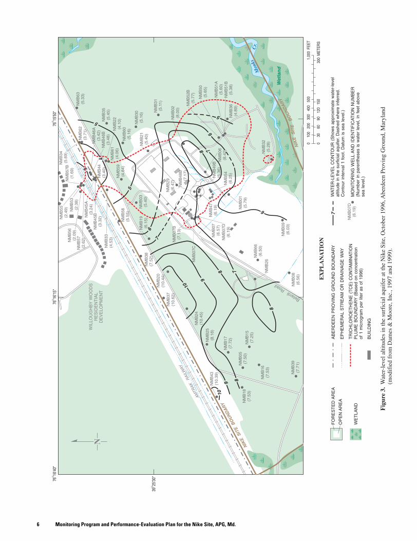
Ground Water—Ground water at the site flows south-southeast toward Monks Creek and north-northwest toward the northern boundary of the installation and the Harford County Sanitary Sewer System (Dames & Moore, Inc., 1997, p. 4–31) (fig. 3). Depth to water in the surficial aquifer generally ranges from 7 to 30 ft bgs near the Former Fueling/Defueling Area and the Northern Boundary Area, respectively (Dames & Moore, Inc., 1997, p. 4–31; 1999). The Remedial Investigation report (Dames & Moore, Inc., 1997) and other Dames & Moore, Inc., reports provide specific detail on water-table elevations throughout a given year. Based on these water-table maps, there is no significant seasonal change in flow direction relative to height of the water table below land surface. For this reason, the head configuration shown in figure 3 is considered to be representative or typical of conditions throughout the year.
Surface Water—The Nike Site is nearly flat with an altitude of approximately 30 ft above sea level. The ground surface slopes gently toward marsh areas to the south, and east towards Monks Creek and associated tributaries. When precipitation is abundant, water collects in wooded areas where drainage is poor due to the low permeability soils (Dames & Moore, Inc., 1999).
Water Use—The current drinking-water supply for residents of the Edgewood Area of APG and areas adjacent to APG is obtained from the Harford County public water supply. This drinking water is a mix of Perryman well field water and treated water from the Susquehanna River (Harford County Government, written commun., 1998). There is presently (2000) no evidence of contamination from the Nike Site to this drinking-water supply.
Climate and Precipitation Climate in Maryland is generally temperate, with average annual precipitation of about 42 inches (van der Leeden and others, 1990, table 1–7). The average high temperature is 90° F (degrees Fahrenheit) in the summer and 40° F in the winter. The average low temperatures are 65° F and 25° F, respectively.
Extent of Contamination TCE has been selected as the single contaminant of concern (COC) at the Nike Site that will be monitored and remediated using a pump-and-treat system (Dames & Moore, Inc., 1996, p. 2–7). The spatial extent of the contaminant plume (defined in the ROD as TCE concentration greater than 1 µg/L) in ground-water samples from geoprobes and monitoring wells used during the Remedial Investigation is shown in figure 3. The TCE contamination in ground water is probably a result of the use and handling of solvents and cleaning agents in and around the Former Maintenance and Fueling/Defueling Area of the Nike Site (Nemeth, 1989; Dames & Moore, Inc., 1996). Concentrations as high as 299 µg/L TCE 3 have been detected near the west-central part of the plume (Dames & Moore, Inc., 1996, p. 2–7). The directions of ground-water flow affecting plume migration are predominantly to the south-southeast toward Monks Creek and to the north toward the APG boundary (fig. 3). The surficial and confined aquifers do not appear to be hydraulically interconnected due to the presence of a continuous confining layer of clay, so the contamination in the surficial aquifer is not expected to migrate downward (Dames & Moore, Inc., 1996, p. 2–7).
Environmental Receptors The 1996 ROD states that the RI concluded that widespread low-level organic chemical contamination poses no current threat to human populations or the environment (Dames & Moore, Inc., 1996, p. 2–6). Forested land, open fields, low brush, marshes, and residential areas are located on and around the Nike Site. Flora and fauna in these areas are currently the only known environmental receptors. Willoughby Woods Residential Development, a housing subdivision, is located to the north within approximately 500 ft of the Nike Site’s plume boundary (fig. 3). There have been no TCE detections to date in this subdivision. If future monitoring indicates northward movement of the plume, evaluation of potential impact to the residential area should be considered.
Remedial Action at the Nike SiteThe Nike Site ROD (Dames & Moore, Inc., 1996) called
for the construction and operation of a ground-water- treatment system (fig. 4) to remediate concentrations of TCE to below State and Federal action levels. Although TCE daughter products may have been present at the time of the ROD declaration, TCE was the primary COC and was the only contaminant addressed. The USGS has therefore not been asked to evaluate other contaminants (Donald Green, ECRD, DSHE, APG, written and oral communs., 1999). An extraction-treatment system (Dames & Moore, Inc., 1999) was designed by Dames & Moore, Inc., with “shakedown”
3. The highest TCE concentration found to date at the Nike Site is 299 µg/L. This concentration was found in sample TNMB90A (direct-push probe) collected near monitoring well NMB07A at a sample depth of 1.4 ft above sea level (Dames & Moore, Inc., 1997, p. 4–2).
Monitoring Program and Performance-Evaluation Plan for the Nike Site, APG, Md.6

7Introduction
activities that began in October 1999. These shakedown activities involved the startup, continuous operation of the plant to demonstrate the effective extraction and treatment of contaminated ground water, and the development of plant operations and maintenance manuals (Dames & Moore, Inc., 1999, p. 3–21 and 3–22). Normal plant operations began in January 2000.
Areas contaminated by TCE at concentrations greater than 5 µg/L were targeted zones for the pump-and-treat system (Dames & Moore, Inc., 1999). This remediation goal was agreed upon by APG, regulatory agencies, the surrounding community at large, and the Restoration Advisory Board (RAB). This agreement outlines the investigation, design, and construction of the treatment system. In accordance with CERCLA protocol, this report will use the terms “treatment system,” “extraction system,” and “pump-and-treat” interchangeably to reference the ground-water remediation system designed and built by Dames & Moore, Inc. The 60-gpm (gallons per minute) system consists of eight extraction wells, treatment by liquid phase granular activated carbon (GAC) adsorption, and discharge to surface water (Monks Creek).
Permit and Monitoring RequirementsCERCLA sites, such as the Nike Site at Aberdeen
Proving Ground, do not require State or Federal permits for operation of pump-and-treat systems (Dames & Moore, Inc., 1999, p. 4–1 to 4–2). APG has agreed to collect and analyze samples on a regular basis, however, as outlined under the National Pollution Discharge Elimination System (NPDES) permit (Dames & Moore, Inc., 1996, p. 3–5). Substantive monitoring and reporting requirements of the NPDES permit will be followed to ensure that the water discharged has no adverse effect on the environment (Dames & Moore, Inc., July 1997, written commun., Attachment 1, Appendix B).
AcknowledgmentsThe authors acknowledge the following people and
agencies for their important contributions to this report. Donald Green of the ECRD, DSHE, APG provided site access and support for many aspects of this project. James May and Earl Edris of the USACE WES provided assistance with their Nike Site ground-water-flow model. Jerry Burgess of Roy F. Weston, Inc., and Jeffrey Hutchins of Dames & Moore, Inc., provided valuable technical discussion about the Nike Site. Emitt Witt and
Monitoring Program and Performance-Evaluation Plan for the Nike Site, APG, Md.8
Kurt C. Hinaman of the USGS provided thorough colleague reviews of this report. Dorothy H. Tepper and Earl A. Greene of the USGS provided additional technical reviews. G. Jean Hyatt, Timothy W. Auer, Valerie M. Gaine, and Donna R. Knight of the USGS assisted with publication of this report.
Long-Term Monitoring Program for the Nike Site
This report includes a plan to monitor the Nike Site by sampling six monitoring wells for TCE and a plan to evaluate the extraction-treatment system for a 5-year period. The six-well network surrounds or “brackets” the boundaries of the TCE plume. This bracketing will help indicate plume movement if multiple sampling events show an increase or decrease in concentrations of TCE.
Long-Term Monitoring ObjectivesOriginal LTM objectives (Donald Green, oral commun.,
1999) were designed as strategies to minimize the resources expended for monitoring the Nike Site without compromis-ing quality. These objectives include:
1. Select and maintain a minimized number of sampling points.
2. Choose wells that act as location “triggers” or “trips” to plume movement and have the highest probability of detection of ground-water extraction system “leaks” in hydraulic capture.
3. Maintain surveillance for contaminant migration at the Northern Boundary Area.
4. Minimize frequency of conventional and/or mainstream sampling programs.
5. Utilize less expensive analytical programs instead of conventional and/or mainstream sampling programs.
6. Initiate a streamlined data management and reporting information system.
7. Monitor wells in accordance with APG SOPs (U.S. Army Directorate of Safety, Health and Environment, 1995 and 1999, SOP No. 010, 013, 014, and 029).
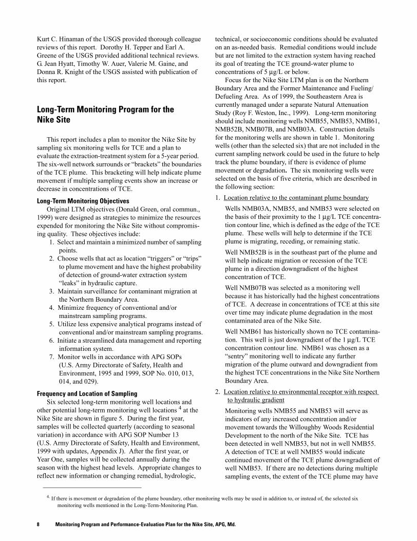
Frequency and Location of SamplingSix selected long-term monitoring well locations and
other potential long-term monitoring well locations 4 at the Nike Site are shown in figure 5. During the first year, samples will be collected quarterly (according to seasonal variation) in accordance with APG SOP Number 13 (U.S. Army Directorate of Safety, Health and Environment, 1999 with updates, Appendix J). After the first year, or Year One, samples will be collected annually during the season with the highest head levels. Appropriate changes to reflect new information or changing remedial, hydrologic,
technical, or socioeconomic conditions should be evaluated on an as-needed basis. Remedial conditions would include but are not limited to the extraction system having reached its goal of treating the TCE ground-water plume to concentrations of 5 µg/L or below.
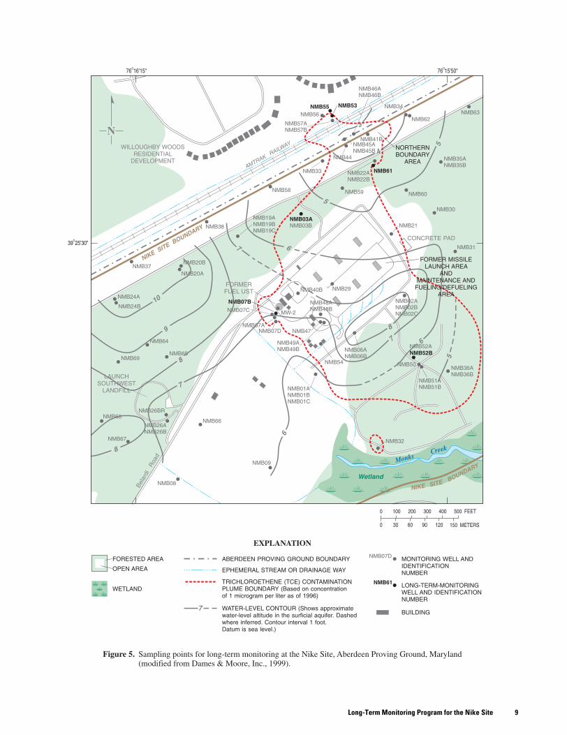
Focus for the Nike Site LTM plan is on the Northern Boundary Area and the Former Maintenance and Fueling/Defueling Area. As of 1999, the Southeastern Area is currently managed under a separate Natural Attenuation Study (Roy F. Weston, Inc., 1999). Long-term monitoring should include monitoring wells NMB55, NMB53, NMB61, NMB52B, NMB07B, and NMB03A. Construction details for the monitoring wells are shown in table 1. Monitoring wells (other than the selected six) that are not included in the current sampling network could be used in the future to help track the plume boundary, if there is evidence of plume movement or degradation. The six monitoring wells were selected on the basis of five criteria, which are described in the following section:1. Location relative to the contaminant plume boundary
Wells NMB03A, NMB55, and NMB53 were selected on the basis of their proximity to the 1 µg/L TCE concentra-tion contour line, which is defined as the edge of the TCE plume. These wells will help to determine if the TCE plume is migrating, receding, or remaining static.Well NMB52B is in the southeast part of the plume and will help indicate migration or recession of the TCE plume in a direction downgradient of the highest concentration of TCE.Well NMB07B was selected as a monitoring well because it has historically had the highest concentrations of TCE. A decrease in concentrations of TCE at this site over time may indicate plume degradation in the most contaminated area of the Nike Site.Well NMB61 has historically shown no TCE contamina-tion. This well is just downgradient of the 1 µg/L TCE concentration contour line. NMB61 was chosen as a “sentry” monitoring well to indicate any further migration of the plume outward and downgradient from the highest TCE concentrations in the Nike Site Northern Boundary Area.
2. Location relative to environmental receptor with respect to hydraulic gradient
Monitoring wells NMB55 and NMB53 will serve as indicators of any increased concentration and/or movement towards the Willoughby Woods Residential Development to the north of the Nike Site. TCE has been detected in well NMB53, but not in well NMB55. A detection of TCE at well NMB55 would indicate continued movement of the TCE plume downgradient of well NMB53. If there are no detections during multiple sampling events, the extent of the TCE plume may have
4. If there is movement or degradation of the plume boundary, other monitoring wells may be used in addition to, or instead of, the selected six monitoring wells mentioned in the Long-Term-Monitoring Plan.
9Long-Term Monitoring Program for the Nike Site
Monitoring Program and Performance-Evaluation Plan for the Nike Site, APG, Md.10
Tabl
e 1.
Wel
l con
stru
ctio
n de
tail
s an
d tr
ichl
oroe
then
e (T
CE
) co
ncen
trat
ions
for
mon
itor
ing
wel
ls a
t the
For
mer
Nik
e Si
te,
Abe
rdee
n P
rovi
ng G
roun
d, M
aryl
and
[Fro
m D
ames
& M
oore
, Inc
., 19
95a,
199
6, 1
999
and
Roy
F. W
esto
n, In
c., 1
999,
200
0a; T
CE,
tric
hlor
oeth
ene;
no.
, num
ber;
nd, n
on-d
etec
t]
NU
MB
ER
OF
SA
MP
LIN
G E
VE
NT
S P
ER
YE
AR
Stat
ion
no.
Mon
itor
ing
wel
lid
enti
fica
tion
Loc
atio
n
Ver
tica
lta
rget
area
of surf
icia
laq
uife
r
TC
Eco
ncen
trat
ion
dete
cted
(par
tspe
rbi
llion
)
Lan
dsu
rfac
eel
evat
ion
(fee
t ab
ove
sea
leve
l)
Top
of
casi
ngel
evat
ion
(fee
t ab
ove
sea
leve
l)
Bor
ing
dept
h(f
eet
belo
wla
ndsu
rfac
e)
Dep
thto sc
reen
bott
om(f
eet
belo
wla
ndsu
rfac
e)
Wel
lsc
reen
leng
th(f
eet)
Wel
lsc
reen
diam
eter
(inc
hes)
Yea
r 1
Yea
r2
Yea
r3
Yea
r4
Yea
r5
1N
MB
55N
orth
ern
B
ound
ary
A
rea
Low
ernd
31.1
033
.53
4545
102.
04
11
14
2N
MB
53N
orth
ern
B
ound
ary
A
rea
Upp
er/
Low
er12
.90
21.8
524
.02
3737
102.
04
11
14
3N
MB
61N
orth
ern
B
ound
ary
A
rea
Upp
ernd
28.4
830
.71
5046
102.
04
11
14
4N
MB
52B
Sout
heas
tern
Are
aU
pper
/L
ower
18.0
021
.52
23.8
527
273
2.0
41
11
4
5N
MB
07B
Form
er
M
aint
enan
ce
and
Fu
elin
g/
Def
uelin
g
Are
a
Upp
er/
Low
er25
8.00
14.6
317
.09
1515
62.
04
11
14
6N
MB
03A
Form
er
M
aint
enan
ce
and
Fu
elin
g/
Def
uelin
g
Are
a
Low
er6.
7920
.40
21.7
519
195
4.0
41
11
4
11Long-Term Monitoring Program for the Nike Site
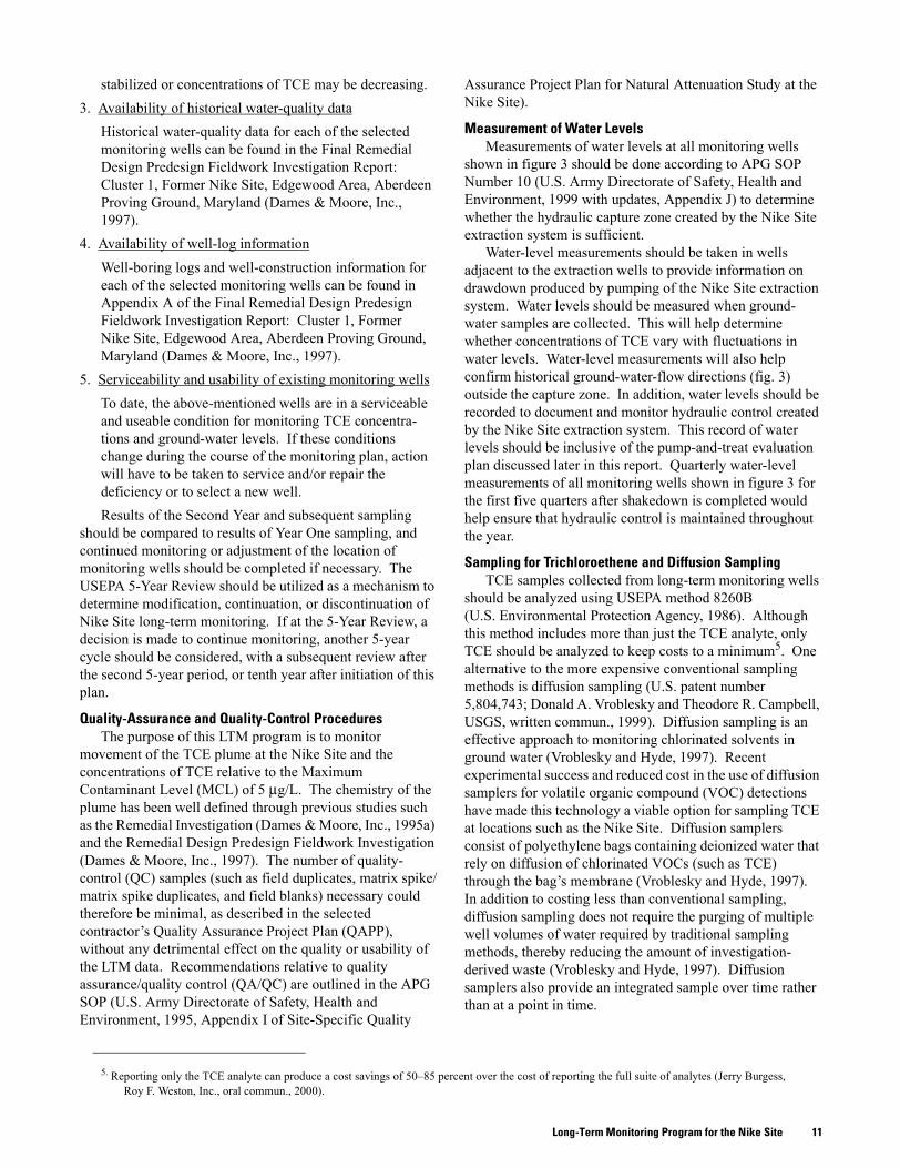
stabilized or concentrations of TCE may be decreasing.3. Availability of historical water-quality data
Historical water-quality data for each of the selected monitoring wells can be found in the Final Remedial Design Predesign Fieldwork Investigation Report: Cluster 1, Former Nike Site, Edgewood Area, Aberdeen Proving Ground, Maryland (Dames & Moore, Inc., 1997).
4. Availability of well-log informationWell-boring logs and well-construction information for each of the selected monitoring wells can be found in Appendix A of the Final Remedial Design Predesign Fieldwork Investigation Report: Cluster 1, Former Nike Site, Edgewood Area, Aberdeen Proving Ground, Maryland (Dames & Moore, Inc., 1997).
5. Serviceability and usability of existing monitoring wellsTo date, the above-mentioned wells are in a serviceable and useable condition for monitoring TCE concentra-tions and ground-water levels. If these conditions change during the course of the monitoring plan, action will have to be taken to service and/or repair the deficiency or to select a new well.Results of the Second Year and subsequent sampling
should be compared to results of Year One sampling, and continued monitoring or adjustment of the location of monitoring wells should be completed if necessary. The USEPA 5-Year Review should be utilized as a mechanism to determine modification, continuation, or discontinuation of Nike Site long-term monitoring. If at the 5-Year Review, a decision is made to continue monitoring, another 5-year cycle should be considered, with a subsequent review after the second 5-year period, or tenth year after initiation of this plan.
Quality-Assurance and Quality-Control ProceduresThe purpose of this LTM program is to monitor
movement of the TCE plume at the Nike Site and the concentrations of TCE relative to the Maximum Contaminant Level (MCL) of 5 µg/L. The chemistry of the plume has been well defined through previous studies such as the Remedial Investigation (Dames & Moore, Inc., 1995a) and the Remedial Design Predesign Fieldwork Investigation (Dames & Moore, Inc., 1997). The number of quality-control (QC) samples (such as field duplicates, matrix spike/matrix spike duplicates, and field blanks) necessary could therefore be minimal, as described in the selected contractor’s Quality Assurance Project Plan (QAPP), without any detrimental effect on the quality or usability of the LTM data. Recommendations relative to quality assurance/quality control (QA/QC) are outlined in the APG SOP (U.S. Army Directorate of Safety, Health and Environment, 1995, Appendix I of Site-Specific Quality
Assurance Project Plan for Natural Attenuation Study at the Nike Site).
Measurement of Water LevelsMeasurements of water levels at all monitoring wells
shown in figure 3 should be done according to APG SOP Number 10 (U.S. Army Directorate of Safety, Health and Environment, 1999 with updates, Appendix J) to determine whether the hydraulic capture zone created by the Nike Site extraction system is sufficient.
Water-level measurements should be taken in wells adjacent to the extraction wells to provide information on drawdown produced by pumping of the Nike Site extraction system. Water levels should be measured when ground-water samples are collected. This will help determine whether concentrations of TCE vary with fluctuations in water levels. Water-level measurements will also help confirm historical ground-water-flow directions (fig. 3) outside the capture zone. In addition, water levels should be recorded to document and monitor hydraulic control created by the Nike Site extraction system. This record of water levels should be inclusive of the pump-and-treat evaluation plan discussed later in this report. Quarterly water-level measurements of all monitoring wells shown in figure 3 for the first five quarters after shakedown is completed would help ensure that hydraulic control is maintained throughout the year.
Sampling for Trichloroethene and Diffusion SamplingTCE samples collected from long-term monitoring wells
should be analyzed using USEPA method 8260B (U.S. Environmental Protection Agency, 1986). Although this method includes more than just the TCE analyte, only TCE should be analyzed to keep costs to a minimum5. One alternative to the more expensive conventional sampling methods is diffusion sampling (U.S. patent number 5,804,743; Donald A. Vroblesky and Theodore R. Campbell, USGS, written commun., 1999). Diffusion sampling is an effective approach to monitoring chlorinated solvents in ground water (Vroblesky and Hyde, 1997). Recent experimental success and reduced cost in the use of diffusion samplers for volatile organic compound (VOC) detections have made this technology a viable option for sampling TCE at locations such as the Nike Site. Diffusion samplers consist of polyethylene bags containing deionized water that rely on diffusion of chlorinated VOCs (such as TCE) through the bag’s membrane (Vroblesky and Hyde, 1997). In addition to costing less than conventional sampling, diffusion sampling does not require the purging of multiple well volumes of water required by traditional sampling methods, thereby reducing the amount of investigation-derived waste (Vroblesky and Hyde, 1997). Diffusion samplers also provide an integrated sample over time rather than at a point in time.
5. Reporting only the TCE analyte can produce a cost savings of 50–85 percent over the cost of reporting the full suite of analytes (Jerry Burgess, Roy F. Weston, Inc., oral commun., 2000).
Monitoring Program and Performance-Evaluation Plan for the Nike Site, APG, Md.12
Ground-Water-Flow ModelingA steady-state ground-water-flow model for the
Nike Site was constructed and calibrated by the USACE WES (1998). The modeling system chosen for the Nike Site application was the Department of Defense Goundwater Modeling System (GMS) (U.S. Army Corps of Engineers Waterways Experiment Station, 1998, p. 5). The model simulated several different extraction scenarios and was used to help evaluate the number of wells, well locations, and extraction rates for the design of the pump-and-treat system. Because the design of the extraction system was based on a specific scenario used in the modeling (U.S. Army Corps of Engineers Waterways Experiment Station, 1998, Scenario D), it is anticipated that the ground-water-flow model could also be used as a tool to evaluate potential effects of adjusting pumping rates in the extraction wells as conditions change at the site.
Data collected on pumping rates from the extraction wells and the associated cones of depression collected during the shakedown period for the extraction and treatment system can be used to test the accuracy of the existing ground-water-flow model. These data can be used to validate the model and aid in determining whether the model can successfully simulate a cone of depression that is close to that observed for a given pumping rate at an extraction well. This comparison can then be used to evaluate whether the model is a good predictive tool for the future performance of the extraction system. If the model is validated as is or with minor adjustments, it could prove a valuable tool in optimizing the extraction rates over the life of the pump-and-treat system.
The objective of optimizing the extraction system at the Nike Site is to minimize the sum of pumping rates while ensuring hydraulic capture of the TCE plume. This can be accomplished with optimization modeling, which uses numerical methods to determine an optimal method of achieving an objective given multiple constraints (Tenbus and Fleck, 1999).
Performance-Evaluation Plan for the Nike Site Ground-Water Extraction System
The performance monitoring and evaluation program for the Nike Site at APG is designed to determine whether ground-water contamination is moving off-site at concentrations that warrant further study or action. Selection of monitoring well locations, discussed in the “Long-Term Monitoring Program for the Nike Site” section, was based in part on the highest probability of detection of ground-water extraction system “leaks” in hydraulic capture. The Data-Quality Objective Process of the U.S. Environmental Protection Agency (1993) was used to help design the monitoring and sampling program for the Nike Site.
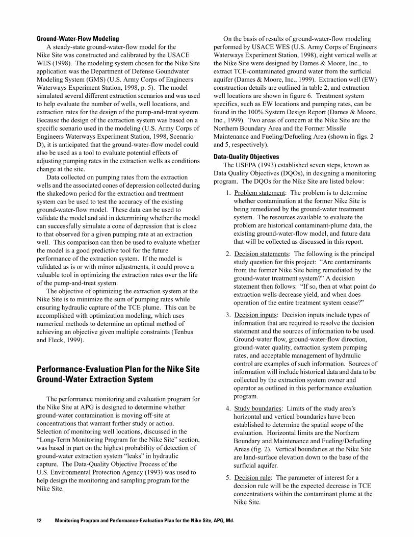
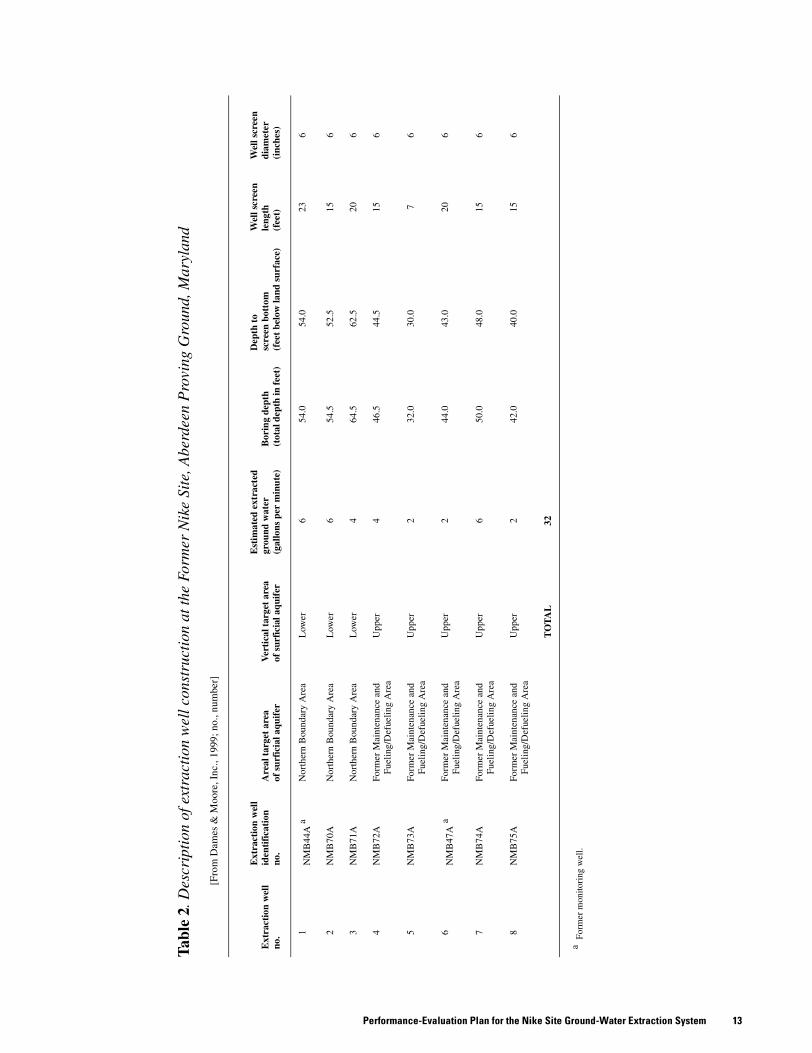
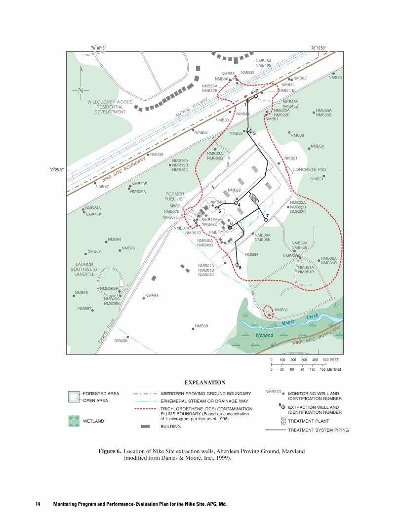
On the basis of results of ground-water-flow modeling performed by USACE WES (U.S. Army Corps of Engineers Waterways Experiment Station, 1998), eight vertical wells at the Nike Site were designed by Dames & Moore, Inc., to extract TCE-contaminated ground water from the surficial aquifer (Dames & Moore, Inc., 1999). Extraction well (EW) construction details are outlined in table 2, and extraction well locations are shown in figure 6. Treatment system specifics, such as EW locations and pumping rates, can be found in the 100% System Design Report (Dames & Moore, Inc., 1999). Two areas of concern at the Nike Site are the Northern Boundary Area and the Former Missile Maintenance and Fueling/Defueling Area (shown in figs. 2 and 5, respectively).
Data-Quality ObjectivesThe USEPA (1993) established seven steps, known as
Data Quality Objectives (DQOs), in designing a monitoring program. The DQOs for the Nike Site are listed below:
1. Problem statement: The problem is to determine whether contamination at the former Nike Site is being remediated by the ground-water treatment system. The resources available to evaluate the problem are historical contaminant-plume data, the existing ground-water-flow model, and future data that will be collected as discussed in this report.
2. Decision statements: The following is the principal study question for this project: “Are contaminants from the former Nike Site being remediated by the ground-water treatment system?” A decision statement then follows: “If so, then at what point do extraction wells decrease yield, and when does operation of the entire treatment system cease?”
3. Decision inputs: Decision inputs include types of information that are required to resolve the decision statement and the sources of information to be used. Ground-water flow, ground-water-flow direction, ground-water quality, extraction system pumping rates, and acceptable management of hydraulic control are examples of such information. Sources of information will include historical data and data to be collected by the extraction system owner and operator as outlined in this performance evaluation program.
4. Study boundaries: Limits of the study area’s horizontal and vertical boundaries have been established to determine the spatial scope of the evaluation. Horizontal limits are the Northern Boundary and Maintenance and Fueling/Defueling Areas (fig. 2). Vertical boundaries at the Nike Site are land-surface elevation down to the base of the surficial aquifer.
5. Decision rule: The parameter of interest for a decision rule will be the expected decrease in TCE concentrations within the contaminant plume at the Nike Site.
13Performance-Evaluation Plan for the Nike Site Ground-Water Extraction System
Tabl
e 2.
Des
crip
tion
of e
xtra
ctio
n w
ell c
onst
ruct
ion
at th
e Fo
rmer
Nik
e Si
te, A
berd
een
Pro
ving
Gro
und,
Mar
ylan
d
[Fro
m D
ames
& M
oore
, Inc
., 19
99; n
o., n
umbe
r]
Ext
ract
ion
wel
lno
.
Ext
ract
ion
wel
lid
enti
fica
tion
no.
Are
al t
arge
t ar
eaof
sur
fici
al a
quif
erV
erti
cal t
arge
t ar
eaof
sur
fici
al a
quif
er
Est
imat
ed e
xtra
cted
grou
nd w
ater
(gal
lons
per
min
ute)
Bor
ing
dept
h(t
otal
dep
th in
feet
)
Dep
th t
o sc
reen
bot
tom
(fee
t be
low
land
sur
face
)
Wel
l scr
een
leng
th(f
eet)
Wel
l scr
een
diam
eter
(inc
hes)
1N
MB
44A
aN
orth
ern
Bou
ndar
y A
rea
Low
er6
54.0
54.0
236
2N
MB
70A
Nor
ther
n B
ound
ary
Are
aL
ower
654
.552
.515
6
3N
MB
71A
Nor
ther
n B
ound
ary
Are
aL
ower
464
.562
.520
6
4N
MB
72A
Form
er M
aint
enan
ce a
nd
Fuel
ing/
Def
uelin
g A
rea
Upp
er4
46.5
44.5
156
5N
MB
73A
Form
er M
aint
enan
ce a
nd
Fuel
ing/
Def
uelin
g A
rea
Upp
er2
32.0
30.0
76
6N
MB
47A
aFo
rmer
Mai
nten
ance
and
Fu
elin
g/D
efue
ling
Are
aU
pper
244
.043
.020
6
7N
MB
74A
Form
er M
aint
enan
ce a
nd
Fuel
ing/
Def
uelin
g A
rea
Upp
er6
50.0
48.0
156
8N
MB
75A
Form
er M
aint
enan
ce a
nd
Fuel
ing/
Def
uelin
g A
rea
Upp
er2
42.0
40.0
156
TO
TA
L32
a F
orm
er m
onito
ring
wel
l.
Monitoring Program and Performance-Evaluation Plan for the Nike Site, APG, Md.14

15Performance-Evaluation Plan for the Nike Site Ground-Water Extraction System
6. Limits on decision errors: Once the range of parameters is defined, then the decision errors will be determined.
7. Optimization of the extraction-well network: The extraction-well network should be reviewed on an as-needed basis to determine the efficiency of extraction wells relative to the cost of operation and maintenance at full performance as designed. This optimization should be performed using the USACE WES ground-water-flow model while comparing pre-start-up data, start-up data, and data from post-start-up analyses. Extraction-well yield and hydraulic containment of the plume are limiting factors in optimization.
TasksThe purpose of this section is to describe the proposed
extraction-system evaluation program through containment and aquifer restoration monitoring (U.S. Environmental Protection Agency, 1996) at the Nike Site. Hydraulic characterization and TCE-contaminant plume character-ization are necessary to properly evaluate site clean-up progress at the site. Considerable information about the hydrogeology and contamination of the Nike Site is presented in the RI/FS reports (Dames & Moore, Inc., 1995a, b). The RI/FS established a baseline that can be used to evaluate the effectiveness of the treatment system. Results from future data-collection efforts can be compared to this baseline data to determine whether the remedial efforts were successful. In summary, the site characterization can be determined by:
• TCE plume boundaries,• Pre-pumping (unstressed) hydraulic-head distribution,• Pumping rates for the extraction wells,• Cones of influence and zones of hydraulic capture for
the extraction wells,• Hydraulic head during extraction, and• Comparing results of the predictive simulations made
with the existing ground-water-flow model with real extraction data.
The evaluation program can be implemented on the basis of this baseline characterization. The evaluation program includes the following activities:
• Sample for TCE at six LTM wells (see section on Long-Term Monitoring Program for the Nike Site) and at extraction-well locations;
• Measure water levels to produce potentiometric, or head, maps for wells (shown in figure 3);
• Use a decision-tree as a guide for input variables to the USACE WES ground-water-flow model and to adjust for changes needed for system optimization;
• Use USACE WES ground-water-flow model output to manage extraction system; and
• Submit milestone results to regulatory agencies (USEPA and MDE) and assess TCE contamination at the USEPA 5-Year Review for the Nike Site.
Ground-Water Extraction System Optimization and Evaluation The 100% Remedial Design (Dames & Moore, Inc., 1999, p. 3–9 and 3–10) indicates that extraction wells 1, 2, and 3 (fig. 6) will be used to remove TCE-contaminated water from the lower two-thirds of the surficial aquifer in the Northern Boundary Area. Concentrations of TCE as high as 43.4 µg/L were detected in this area; the removal action level is 5 µg/L. Extraction Wells 4 through 8 will remove water from the upper part of the surficial aquifer at the Former Missile Maintenance and Fueling/Defueling Area. Concentrations of TCE as high as 299 µg/L were detected in direct-push probe samples in the vicinity of well NMB07 (direct-push probe TNMB90A, Dames & Moore, Inc., 1997, p. 4–2).
After the results of simulations made with the USACE WES ground-water-flow model have been compared to actual system performance and the model input parameters adjusted if necessary, any significant change to plume and site conditions, such as changes in water-table elevation or plume boundaries, could be simulated in the model as a new scenario. Over time, changes in the plume boundary could allow for possible modifications to the extraction-well pumping rate configuration (table 2). This could result in cost savings for the operation and maintenance of the system. Alternatively, if some extraction wells are more effective than others at contaminant removal, alterations to the extraction-well pumping rate configuration could speed the site remediation time. Such alterations could include periodic shutting off and restarting pumps at one or more EWs, varying the pumping rates of one or more EWs, long-term shutdown of one or more EWs, and/or closure of one or more EWs.
An effective way to analyze different extraction scenarios is through the use of optimization software coupled with the USACE WES ground-water-flow model (U.S. Army Corps of Engineers Waterways Experiment Station, 1998). With appropriate objectives and constraints, a ground-water management model can be used to determine numerically optimal extraction configurations for a variety of conditions. The process is relatively quick, accurate, and sufficiently flexible to adjust simulation of changes in objectives or constraints. In addition to the flexibility of the extraction system at the Nike Site, this modeling method could prove to be extremely useful in optimizing the performance of the Nike Site remedial system.
Treatment System Sampling and Analysis In addition to sampling requirements outlined in a previous section, “Permit and Monitoring Requirements,” the following sampling schedule is suggested. The data collected from the initial sampling of the eight extraction wells will be used to determine where and at what concentrations TCE is present at the site. Sampling of the extraction wells should be performed in accordance with APG SOP Numbers 14 and 29 (U.S. Army Directorate of Safety, Health and Environment,
Monitoring Program and Performance-Evaluation Plan for the Nike Site, APG, Md.16
1995 with updates, Appendix J). Water levels should be measured and TCE concentrations should be sampled at the six LTM wells to determine hydraulic control and TCE distribution, respectively.
Water levels will be measured manually on both a scheduled basis and a situation-specific basis, as determined by professional judgment of APG (or contractor carrying out plan). Water-level data will be documented so that trends can be established.
EW1 and EW6 are converted monitoring wells NMB44A and NMB47A, respectively. Historical data for these two monitoring wells, as well as the pre-startup sampling of the eight extraction wells, show steady-state conditions in ground water at the Nike Site. As the monitoring program progresses, any subsequent decrease in monitoring frequency should be justified on the basis of a significant supporting trend over various seasons.
Description of Decision Points The objective of the following section is to provide sufficient explanation of the decision matrix (shown in figs. 7 and 8) so that the ground-water extraction system can be effectively managed to achieve the remedial actions outlined in the ROD in a timely manner. Conversely, this decision matrix can also be used as a tool to determine the practicality of continuing the use of an engineered clean-up system instead of monitored natural attenuation, LTM, or site closure.
Decision Matrix for Optimizing Extraction System The decision matrix, or decision tree, presented in figure 7 can be used as a tool to manage the extraction-well network on the basis of sampling results from perimeter, or “sentry,” monitoring wells. The key component of the decision tree is the successful use of the USACE WES ground-water-flow model simulation results, which are used to modify the extraction-well network in such a way that hydraulic capture of the TCE plume is maintained whether the plume is expanding or contracting.Decision Point 1A. Is concentration of contaminant of
concern (COC) in the monitoring well decreasing or increasing?If the answer is “no,” the COC (TCE for the Nike Site)
is above State and Federal action levels (5 µg/L) and not increasing or decreasing markedly, then pumping rates from the extraction wells should remain the same and monitoring should continue. If “yes,” there are increasing or decreasing concentrations of TCE at the monitoring well, and decision point B should be followed, to adjust the TCE concentration contour line accordingly.
Decision Point 1B. Is there a significant data trend to justify new COC contour lines?Historical TCE concentration data and contour maps
should be utilized to compare current site conditions relative to TCE contamination, and a significant difference in concentration contours should be sought.
If “no, there is not a significant difference,” continue to monitor this well until a reasonable trend or change can
be established. In some cases, professional judgment by APG or its contractor may be needed to identify such a trend or change.
If “yes,” a trend or significant bias can justify an inward shift in plume boundaries, and a new model scenario should be run. The USACE WES ground-water-flow model would simulate a smaller plume that could potentially result in adjustment of extraction system pumping rates.
One important feature of the USACE WES ground-water-flow model is its ability to calculate hydraulic capture of plume boundaries. Although the extraction well may be producing “clean” water, the effects of “throttling down” the pump or shutting the pump off would impact hydraulic capture as it was originally designed (Dames & Moore, Inc., 1999). Serious consideration should be given before reducing yield at a particular extraction well in light of the overall goals of the extraction system and plume migration.
Decision Point 1C. Does the USACE WES ground-water-flow model support modifications to the existing extraction system configuration?If “no,” maintain the current pumping configuration of
the system and continue to monitor. Monitoring wells should be monitored frequently, so that any changes indicating degradation of the contaminant plume can be detected. If sampling of a particular well on a quarterly basis reveals no change in detected concentrations of TCE, then semi-annual or annual sampling may be appropriate and adequate. Minimal sampling on an as-needed basis rather than set sampling schedules with numerous sampling locations would reduce costs.
If “yes,” and if technically reasonable, implement modifications to system pumping configurations according to USACE WES ground-water-flow model scenarios. Modifications may be as minor as throttling down the pumping rate of one well from 3 gpm to 2 gpm or as significant as shutting off an extraction well while significantly reducing pumping rates in multiple extraction wells.Decision Matrix for Determining System Shutdown The
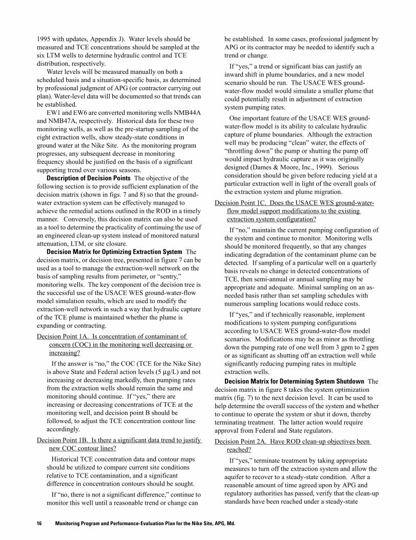
decision matrix in figure 8 takes the system optimization matrix (fig. 7) to the next decision level. It can be used to help determine the overall success of the system and whether to continue to operate the system or shut it down, thereby terminating treatment. The latter action would require approval from Federal and State regulators.Decision Point 2A. Have ROD clean-up objectives been
reached?If “yes,” terminate treatment by taking appropriate
measures to turn off the extraction system and allow the aquifer to recover to a steady-state condition. After a reasonable amount of time agreed upon by APG and regulatory authorities has passed, verify that the clean-up standards have been reached under a steady-state

17Performance-Evaluation Plan for the Nike Site Ground-Water Extraction System
Monitoring Program and Performance-Evaluation Plan for the Nike Site, APG, Md.18
19Summary
condition. Final disposition of the treatment system will depend on decisions by Federal and State regulators.
If “no,” continue to modify the system as practical. Adjust the USACE WES ground-water-flow model scenario to reflect changes to the extraction network.
Decision Point 2B. After modification, is there a significant trend in overall plume degradation?If “yes,” return to decision Point 2A, “Have ROD
clean-up objectives been reached?”If “no,” then continued monitoring is indicated. At the
5-Year Review stage (or at another acceptable timeframe), evaluate whether cleaning up the aquifer is technically impracticable. An appropriate timeframe could be determined by use of the existing ground-water-flow model. The model could be used to evaluate the length of time it takes to flush a complete volume of water through the aquifer system at the Nike Site. After one or more aquifer volumes have gone through the system, some reduction of the contaminant plume should have occurred. If no such reduction has been observed, an alternative remedy or a technical impracticability waiver may be more appropriate than continued use of the pump-and-treat system. If State and Federal regulators approve a waiver for technical impracticability, then the next step would be a consensual agreement on modifying remedial action objectives, which would be specified in an amended ROD.
Summary
Trichloroethene has been detected at concentrations up to 299 micrograms per liter at the Former Nike Missile Battery Site (Nike Site) during the Remedial Investigation under the Comprehensive Environmental Response, Compensation, and Liability Act Program. This report provides Aberdeen Proving Ground with a framework to evaluate the ground-water extraction system at the Nike Site so that the remedial goals are efficiently and effectively achieved in accordance with the 1996 Record of Decision, and to provide criteria on when to shutdown the treatment system, when its useful life is over. This report is based on existing data and interpretations described in the Remedial Investigation/Feasibility Study process, and the 100% Remedial Design of the extraction-treatment system. As stipulated in the September 1996 Record of Decision, eight extraction wells pumping a total of approximately 32 gallons per minute will be closely monitored and evaluated to determine capture and treatment of the trichloroethene plume at the Nike Site. The Record of Decision also requires long-term monitoring of the Nike Site.
The long-term monitoring program for the Nike Site described in this report recommends the use of six monitoring wells to track the trichloroethene-contamination plume. This report also includes a plan to evaluate the extraction-treatment system for a 5-year period, which will be followed by a U.S. Environmental Protection Agency 5-Year Review to determine the future of the Nike Site. During the first year, sampling will be done on a quarterly basis. After the first year, samples will be collected annually during the season with the highest water-table elevations.
The pump-and-treat evaluation part of this program utilizes a decision-tree matrix, a ground-water-flow model developed by the U.S. Army Corps of Engineers Waterways Experiment Station, and analysis of actual pumping results to help run the treatment system efficiently while maintaining hydraulic control of the contaminant plume. On the basis of new extraction-system modifications indicated in the decision-tree matrix and in numerical simulations designed to optimize pumping efficiency, the extraction system pumping configuration and long-term monitoring program can be modified. This report provides a necessary and flexible plan to accommodate changing plume boundaries and site conditions while evaluating the performance of the Nike Site extraction system.
Monitoring Program and Performance-Evaluation Plan for the Nike Site, APG, Md.20
Baker Environmental, Inc., 1998, Long-term monitoring work plan: Operable Unit No. 2 (Sites 6 and 82): U.S. Marine Corps Base, Camp Lejeune, North Carolina: Consultant’s report for Department of the Navy, Atlantic Division, Naval Facilities Engineering Command, Norfolk, Va., [variously paged].
Dames & Moore, Inc., 1990, Preliminary Assessment/Site Investigation, Cluster 1, Former Nike Site, Edgewood Area, Aberdeen Proving Ground, Maryland: Consultant’s report for U.S. Army Corps of Engineers: Waterways Experiment Station, Vicksburg, Miss., [variously paged].
_____ 1995a, Final Remedial Investigation/Feasibility Study, Part 1: Remedial Investigation, Cluster 1, Former Nike Site, Edgewood Area, Aberdeen Proving Ground, Maryland: Consultant’s report for U.S. Army Corps of Engineers Waterways Experiment Station, Vicksburg, Miss., [variously paged].
_____ 1995b, Final Remedial Investigation/Feasibility Study, Part 2: Feasibility Study, Cluster 1, Former Nike Site, Edgewood Area, Aberdeen Proving Ground, Maryland: Consultant’s report for U.S. Army Corps of Engineers Waterways Experiment Station, Vicksburg, Miss., [variously paged].
_____ 1996, Final Record of Decision: Cluster 1, Former Nike Site, Edgewood Area, Aberdeen Proving Ground, Maryland: Consultant’s report for U.S. Army Corps of Engineers Waterways Experiment Station, Vicksburg, Miss., 89 p., plus appendixes.
_____ 1997, Final Remedial Design Predesign Fieldwork Investigation Report: Cluster 1, Former Nike Site, Edgewood Area, Aberdeen Proving Ground, Maryland: Consultant’s report for Hazardous Waste Remedial Actions Program, Oak Ridge, Tenn., 237 p., plus appendixes.
_____ 1999, Final Groundwater Treatment System 100% Design Report: Cluster 1, Former Nike Site, Edgewood Area, Aberdeen Proving Ground, Maryland: Consultant’s report for Hazardous Waste Remedial Actions Program, Oak Ridge, Tenn., 56 p., plus appendixes.
Donnelly, C.A, and Tenbus, F.J., 1998, Temporal and vertical variation of hydraulic head in the Edgewood Area, Aberdeen Proving Ground, Maryland: U.S. Geological Survey Water-Resources Investigations Report 98–4047, 26 p.
Drummond, D.D., and Blomquist, J.D., 1993, Hydrogeology, water-supply potential, and water quality of the Coastal Plain aquifers of Harford County, Maryland: Maryland Geological Survey Report of Investigations No. 58, 160 p.
Drummond, D.D. , and Johnston, R.P.B., 1997, Hydrogeology and estimation of ground-water contributing areas of the Perryman Well Field, Harford County, Maryland: Maryland Geological Survey Report of Investigations No. 63, 143 p.
Nemeth, Gary, 1989, Resource Conservation Recovery Act Facilities Assessment, Edgewood Area, Aberdeen Proving Ground, Maryland: Aberdeen Proving Ground, Maryland, Report 39–26–0490–90, 1,158 p.
_____ 1990, Resource Conservation Recovery Act Facilities Investigation, Edgewood Area, Aberdeen Proving Ground, Maryland: Aberdeen Proving Ground, Maryland, [variously paged].
Nyer, Evan, Mayfield, Polly, and Hughes, Joseph, 1998, Beyond the AFCEE protocol for Natural Attenuation: Ground Water Monitoring and Remediation, v. XVIII, no. 3, p. 70–77.
Owens, J.P., 1969, Coastal Plain rocks of Harford County, Maryland, in The geology of Harford County, Maryland: Maryland Geological Survey, p. 77–103.
Roy F. Weston, Inc., 1999, Evaluation of Natural Attenuation at the Southeastern Area, Former Nike Site, Edgewood Area, Aberdeen Proving Ground, Maryland: Consultant’s report for Hazardous Waste Remedial Actions Program, Oak Ridge, Tenn., [variously paged].
_____ 2000a, Nike Site Plume Migration Study, Edgewood Area, Aberdeen Proving Ground, Maryland: Consultant’s report for Hazardous Waste Remedial Actions Program, Oak Ridge, Tenn., 45 p.
_____ 2000b, Natural Attenuation Study of Groundwater at the Southeast Area, Former Nike Site, Edgewood Area, Aberdeen Proving Ground, Maryland: Consultant’s report for Hazardous Waste Remedial Actions Program, Oak Ridge, Tenn., 145 p.
Tenbus, F.J., and Fleck, W.B, 1999, Documentation of work for the optimization project, Canal Creek, Aberdeen Proving Ground, Maryland, October 1, 1997 through September 30, 1998: U.S. Geological Survey Open-File Report 99–76, 124 p.
U.S. Air Force Center for Environmental Excellence, 1997, Long-Term Monitoring Optimization Guide: Headquarters Air Force Center for Environmental Excellence, Consultant Operations Division, Brooks Air Force Base, Tex., 45 p.
U.S. Army Directorate of Safety, Health and Environment, 1995, Aberdeen Proving Ground, June 1995 with updates, Appendix I Standard Operating Procedures, Site–Specific Quality Assurance Project Plan for Natural Attenuation Study at the Nike Site, Environmental Conservation and Restoration Division, Aberdeen Proving Ground, Md., [variously paged].
Selected References
21Selected References
_____ 1999, Aberdeen Proving Ground, December 1999 with updates, Appendix J: Standard Operating Procedures (SOPs), Work Plan for CERCLA Remedial Investigation/Feasibility Study (Generic Work Plan), Environmental Conservation and Restoration Division, Aberdeen Proving Ground, Md. [variously paged]. SOP No. 010 Water Level and Well-Depth Measurements (August 1993), No. 013 Collection of Monitoring Well samples (August 1993), No. 014 Collection of Production Wells Samples (July 1993), and No. 029 Extraction Wells (August 1993).
U.S. Army Corps of Engineers Waterways Experiment Station, 1998, Interim Report on Groundwater Modeling at the Former Nike Site, Aberdeen Proving Grounds [sic], Maryland: U.S. Army Corps of Engineers, Waterways Experiment Station, Vicksburg, Miss., 16 p., plus appendixes.
U.S. Army Ordnance Missile Command, 1959, Nike Ajax historical monograph: Development, production, and deployment of the Nike Ajax guided missile system 1945–1959, Redstone Arsenal, Ala., U.S. Army Ordnance Missile Command, 295 p.
U.S. Environmental Protection Agency, 1986, RCRA Technical Enforcement Guidance Document, OSWER-99: Washington, D.C., USEPA Office of Research and Development, [variously paged].
_____ 1993, Data Quality Objectives process for Superfund: Interim Final Guidance, USEPA/540/G-93/071: Washington, D.C., USEPA Office of Research and Development, [variously paged].
_____ 1996, Pump-and-treat ground-water remediation: A guide for decision makers and practitioners, USEPA/625/R–95/005: Cincinnati, Ohio, USEPA, Office of Research and Development, National Risk Management Research Laboratory, [variously paged].
van der Leeden, Frits, Troise, F.L., and Todd, D.K., 1990, The water encyclopedia (2d ed.): Chelsea, Mich., Lewis Publishers, 808 p.
Vroblesky, D.A., and Hyde, W.T., 1997, Diffusion samplers as an inexpensive approach to monitoring VOCs in ground water: Ground Water Monitoring and Remediation, v. XVII, no. 3, p. 177–184.