Embed Size (px)
Citation preview
Long Range RepeaterInstallation AddendumFor AC- and Solar-Powered Long Range RepeatersModels 7653 and 7654
For Vantage Pro2™ Vantage Vue®Weather Envoy™ Envoy8X™
Davis Instruments, 3465 Diablo Avenue, Hayward, CA 94545-2778 U.S.A. • 510-732-9229 • www.davisnet.com
®
Vantage Pro2™ Long Range Wireless Repeater AddendumRev. B, December 1, 2011Document Part Number: 07395.258For Vantage Pro2 Long Range Wireless Repeaters: 7653, 7654
Compatible with Vantage Pro2 Antennas: 7656, 7660
Vantage Pro2™, Vantage Vue®, and Envoy™ are trademarks of Davis Instruments Corp., Hay-ward, CA. © Davis Instruments Corp. 2011. All rights reserved.
Davis Instruments Quality Management System is ISO 9001 certified.Information in this document subject to change without notice.
3465 Diablo Avenue, Hayward, CA 94545-2778 U.S.A.510-732-9229 • Fax: 510-732-9188
E-mail: [email protected] • www.davisnet.com
®
FCC Part 15 Class B Registration WarningThis equipment has been tested and found to comply with the limits for a Class B digital device, pursuant to Part 15 of the FCC Rules. These limits are designed to provide reasonable protection against harmful interference in a res-idential installation. This equipment generates, uses, and can radiate radio frequency energy and, if not installed and used in accordance with the instructions, may cause harmful interference to radio communications.However, there is no guarantee that interference will not occur in a particular installation. If this equipment does cause harmful interference to radio or television reception, which can be determined by turning the equipment on and off, the user is encouraged to try to correct the interference by one or more of the following measures:• Reorient or relocate the receiving antenna.• Increase the separation between the equipment and receiver.• Connect the equipment into an outlet on a circuit different from that to which the receiver is connected.• Consult the dealer or an experienced radio/TV technician for help.Changes or modification not expressly approved in writing by Davis Instruments may void the warranty and void the user's authority to operate this equipment.FCC ID: IRDWW765YIC: 3788A-765Y
EC EMC ComplianceThis product complies with the essential protection requirements of the EC EMC Directive 2004/108/EC, as tested to the following directives: • ETSI EN 300 220• ETSI EN 301 489This device has been designed to operate with an antenna having a maximum gain of 11 dBi. Antennas having a higher gain are strictly prohibited per regulations of Industry Canada. The required antenna impedance is 50 ohms. To reduce potential radio interference to other users, the antenna type and its gain should be chosen that the equivalent isotropically radiated power (EIRP) is not more than that required for successful communication.
1
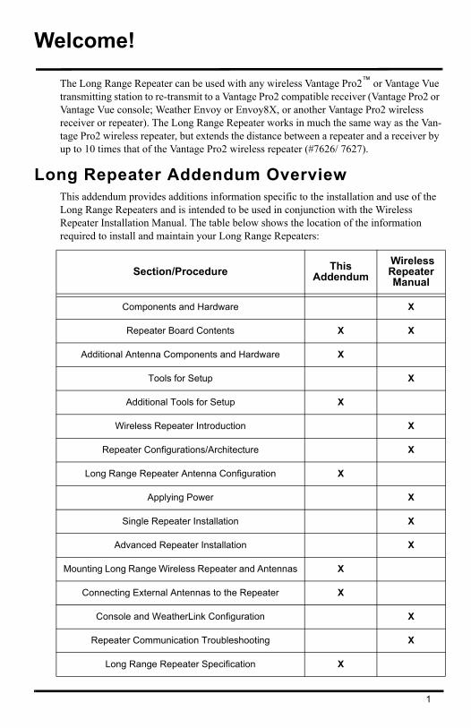
Welcome!
The Long Range Repeater can be used with any wireless Vantage Pro2™ or Vantage Vue transmitting station to re-transmit to a Vantage Pro2 compatible receiver (Vantage Pro2 or Vantage Vue console; Weather Envoy or Envoy8X, or another Vantage Pro2 wireless receiver or repeater). The Long Range Repeater works in much the same way as the Van-tage Pro2 wireless repeater, but extends the distance between a repeater and a receiver by up to 10 times that of the Vantage Pro2 wireless repeater (#7626/ 7627).
Long Repeater Addendum OverviewThis addendum provides additions information specific to the installation and use of the Long Range Repeaters and is intended to be used in conjunction with the Wireless Repeater Installation Manual. The table below shows the location of the information required to install and maintain your Long Range Repeaters:
Section/Procedure This Addendum
Wireless Repeater Manual
Components and Hardware X
Repeater Board Contents X X
Additional Antenna Components and Hardware X
Tools for Setup X
Additional Tools for Setup X
Wireless Repeater Introduction X
Repeater Configurations/Architecture X
Long Range Repeater Antenna Configuration X
Applying Power X
Single Repeater Installation X
Advanced Repeater Installation X
Mounting Long Range Wireless Repeater and Antennas X
Connecting External Antennas to the Repeater X
Console and WeatherLink Configuration X
Repeater Communication Troubleshooting X
Long Range Repeater Specification X
2
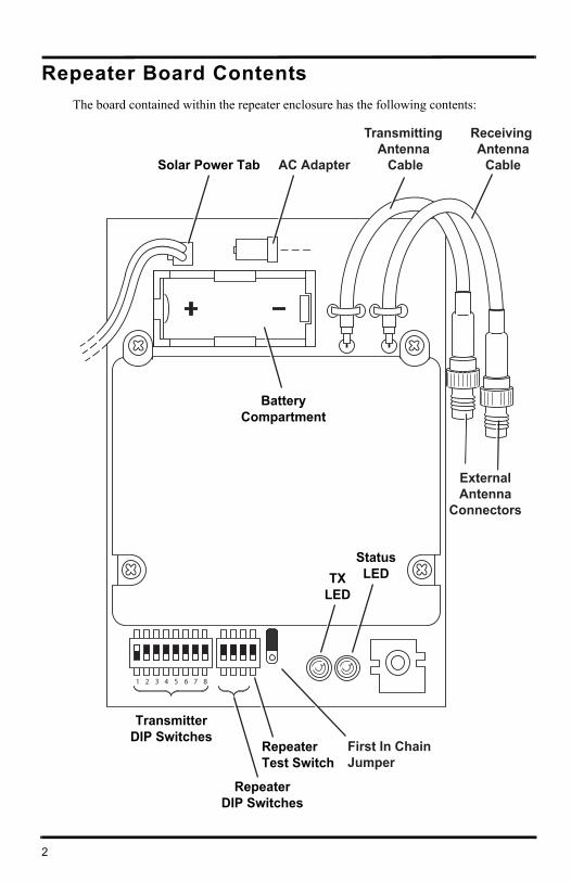
Repeater Board Contents
The board contained within the repeater enclosure has the following contents:
TransmitterDIP Switches
RepeaterDIP Switches
RepeaterTest Switch
TXLED
StatusLED
BatteryCompartment
Solar Power Tab
Receiving Antenna
CableAC Adapter
Transmitting Antenna
Cable
ExternalAntenna
Connectors
First In ChainJumper
1 2 3 4 5 6 7 8
3
The components unique to the Long Range Repeater board are:
• Transmitting Antenna Cable — Connects the repeater to the external transmitting antenna.
• Receiving Antenna Cable — Connects the repeater to the external antenna receiving a station or repeater signal.
Additional Tools for SetupIn addition to the tools required for standard wireless repeater installation, the following additional tool is required to set up and install the long range repeater:
• 1/2'' socket
Long Range Repeater HardwareEach long range repeater requires two antennas, one for receiving a station or wireless repeater, and one for transmitting the data to another repeater or receiver. The two exter-nal antenna choices are:
• Omni-direction
• Yagi (directional) antenna
You must purchase external antennas appropriate to your network architecture require-ments
Note: Davis Instruments sells FCC Type approved antennas for the long range repeater. These antennas are available for US customers only. US customer must use these antennas. Overseas customers are responsible for procuring their own long range antennas for use with the long range wireless repeater that comply with local regulations. See “Specifications” on page 13 for more information.
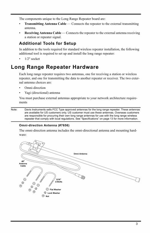
Omni-direction Antenna (#7656)
The omni-direction antenna includes the omni-directional antenna and mounting hard-ware:
Omni Antenna
5/16"U-Bolts
48"Antenna
Cable
Flat Washer
Lock WasherNut
4
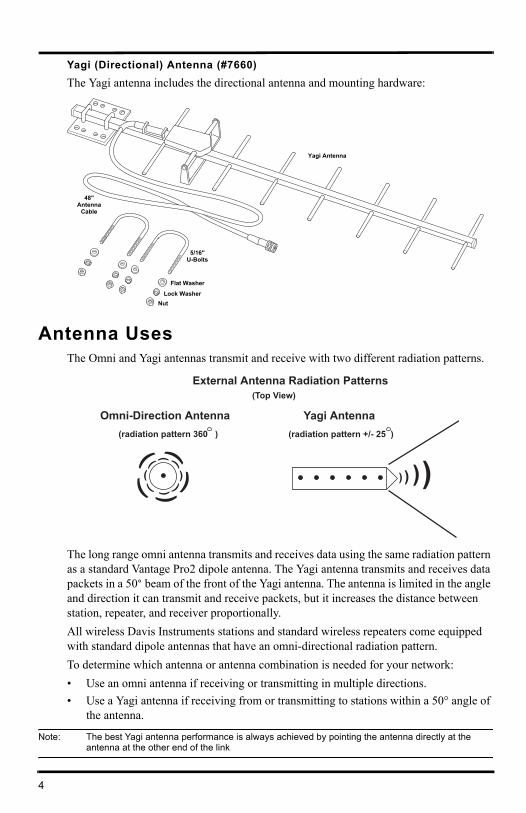
Yagi (Directional) Antenna (#7660)
The Yagi antenna includes the directional antenna and mounting hardware:
Antenna UsesThe Omni and Yagi antennas transmit and receive with two different radiation patterns.
The long range omni antenna transmits and receives data using the same radiation pattern as a standard Vantage Pro2 dipole antenna. The Yagi antenna transmits and receives data packets in a 50° beam of the front of the Yagi antenna. The antenna is limited in the angle and direction it can transmit and receive packets, but it increases the distance between station, repeater, and receiver proportionally.
All wireless Davis Instruments stations and standard wireless repeaters come equipped with standard dipole antennas that have an omni-directional radiation pattern.
To determine which antenna or antenna combination is needed for your network:
• Use an omni antenna if receiving or transmitting in multiple directions.
• Use a Yagi antenna if receiving from or transmitting to stations within a 50° angle of the antenna.
Note: The best Yagi antenna performance is always achieved by pointing the antenna directly at the antenna at the other end of the link
Yagi Antenna
5/16"U-Bolts
48"Antenna
Cable
Flat Washer
Lock WasherNut
External Antenna Radiation Patterns
(radiation pattern 360 )
)
)
)
) )
))
)
))
)
)
)
Omni-Direction Antenna(radiation pattern +/- 25 )
Yagi Antenna
) ) ))
(Top View)
5
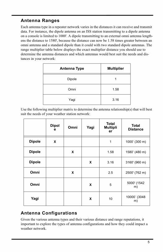
Antenna RangesEach antenna type in a repeater network varies in the distances it can receive and transmit data. For instance, the dipole antenna on an ISS station transmitting to a dipole antenna on a console is limited to 1000'. A dipole transmitting to an external omni antenna length-ens the distance to 1580', because the distance can now be 1.58 times greater between an omni antenna and a standard dipole than it could with two standard dipole antennas. The range multiplier table below displays the exact multiplier distance you should use to determine the antenna distances and which antennas would best suit the needs and dis-tances in your network:
Use the following multiplier matrix to determine the antenna relationship(s) that will best suit the needs of your weather station network:
Antenna ConfigurationsGiven the various antenna types and their various distance and range reputations, it important to explore the types of antenna configurations and how they could impact a weather network.
Antenna Type Multiplier
Dipole 1
Omni 1.58
Yagi 3.16
Dipole Omni Yagi
Total Multipli
er
TotalDistance
Dipole X 1 1000’ (300 m)
Dipole X 1.58 1580’ (480 m)
Dipole X 3.16 3160' (960 m)
Omni X 2.5 2500' (762 m)
Omni X 55000' (1542
m)
Yagi X 1010000´ (3048
m)
6
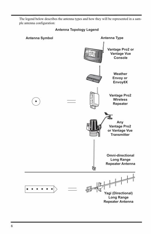
The legend below describes the antenna types and how they will be represented in a sam-ple antenna configuration:
Antenna Topology Legend
Antenna Symbol Antenna Type
Vantage Pro2 orVantage Vue
Console
WeatherEnvoy or Envoy8X
Vantage Pro2WirelessRepeater
AnyVantage Pro2
or Vantage VueTransmitter
Omni-directionalLong Range
Repeater Antenna
Yagi (Directional)Long Range
Repeater Antenna
7
The first symbol represents any station/receiver/repeater with a normal dipole or long range omni antenna. The second symbol represents the long range Yagi antenna.
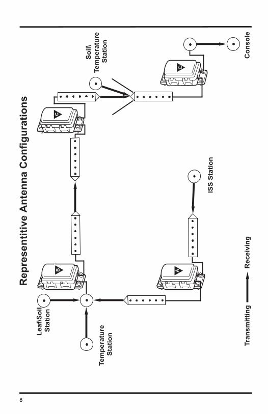
The diagram on the next page contains all the long range external antenna configurations available for a network. In this example, there are four repeaters, each with a unique sta-tion-to-repeater or repeater-to-repeater antenna relationship.
Repeater A has two Yagi antennas, the first antenna receiving data packets from an ISS station with the standard dipole omni antenna. The transmitting Yagi antenna is sending the data packets to Repeater B.
The receiving antenna on Repeater B is an omni antenna, that is collecting data from not only repeater A, but also from two other stations in different directions. The transmitting Yagi antenna is in direct line to the Yagi antenna on Repeater C.
The transmitting antenna on Repeater C is also a Yagi antenna. Repeater C is also sharing a line of sight to Repeater D’s receiving Yagi antenna with another station. The omni transmitting antenna on Repeater D is in range of the console.
Decide which configuration or multiple antenna configurations works best for your net-work before mounting and installing your long range wireless repeaters.
8
A
C
ISS
Stat
ion
Tem
pera
ture
Sta
tionLe
af\S
oil
Sta
tion
B
D
Soil\
Tem
pera
ture
Sta
tion
Con
sole
Tran
smitt
ing
Rec
eivi
ng
Rep
rese
ntiti
ve A
nten
na C
onfig
urat
ions
9
Mounting the Repeater and External AntennasThe antenna configuration and wireless repeater can be mounted on a pole at a designated location. Use the provided U-bolts for the wireless repeater and the U-bolts provided for each antenna type to install them all to a pole.
Note: To accommodate your antenna configuration (omni and Yagi or Yagi and Yagi), mount the antennas first before mounting the wireless repeater enclosure.
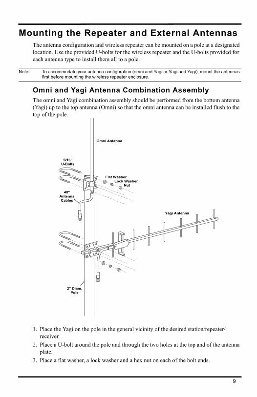
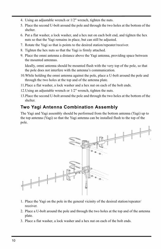
Omni and Yagi Antenna Combination AssemblyThe omni and Yagi combination assembly should be performed from the bottom antenna (Yagi) up to the top antenna (Omni) so that the omni antenna can be installed flush to the top of the pole.
1. Place the Yagi on the pole in the general vicinity of the desired station/repeater/receiver.
2. Place a U-bolt around the pole and through the two holes at the top and of the antenna plate.
3. Place a flat washer, a lock washer and a hex nut on each of the bolt ends.
Omni Antenna
Yagi Antenna
5/16"U-Bolts
Flat WasherLock Washer
Nut
48"AntennaCables
2" Diam.Pole
10
4. Using an adjustable wrench or 1/2" wrench, tighten the nuts.
5. Place the second U-bolt around the pole and through the two holes at the bottom of the shelter.
6. Put a flat washer, a lock washer, and a hex nut on each bolt end, and tighten the hex nuts so that the Yagi remains in place, but can still be adjusted.
7. Rotate the Yagi so that is points to the desired station/repeater/receiver.
8. Tighten the hex nuts so that the Yagi is firmly attached.
9. Place the omni antenna a distance above the Yagi antenna, providing space between the mounted antennas.
Ideally, omni antenna should be mounted flush with the very top of the pole, so that the pole does not interfere with the antenna’s communication.
10.While holding the omni antenna against the pole, place a U-bolt around the pole and through the two holes at the top and of the antenna plate.
11.Place a flat washer, a lock washer and a hex nut on each of the bolt ends.
12.Using an adjustable wrench or 1/2" wrench, tighten the nuts.
13.Place the second U-bolt around the pole and through the two holes at the bottom of the shelter.
Two Yagi Antenna Combination AssemblyThe Yagi and Yagi assembly should be performed from the bottom antenna (Yagi) up to the top antenna (Yagi) so that the Yagi antenna can be installed flush to the top of the pole.
1. Place the Yagi on the pole in the general vicinity of the desired station/repeater/receiver.
2. Place a U-bolt around the pole and through the two holes at the top and of the antenna plate.
3. Place a flat washer, a lock washer and a hex nut on each of the bolt ends.
11
4. Using an adjustable wrench or 1/2" wrench, tighten the nuts.
5. Place the second U-bolt around the pole and through the two holes at the bottom of the shelter.
6. Put a flat washer, a lock washer, and a hex nut on each bolt end, and tighten the hex nuts so that the Yagi remains in place, but can still be adjusted.
7. Rotate the Yagi so that is points to the desired station/repeater/receiver.
8. Tighten the hex nuts so that the Yagi is firmly attached.
9. Rotate the second Yagi so that is points to the desired station/repeater/receiver.
10.While holding the Yagi antenna in the correct alignment against the pole, place a U-bolt around the pole and through the two holes at the top and of the antenna plate.
11.Place a flat washer, a lock washer and a hex nut on each of the bolt ends.
12.Using an adjustable wrench or 1/2" wrench, tighten the nuts.
13.Place the second U-bolt around the pole and through the two holes at the bottom of the shelter.
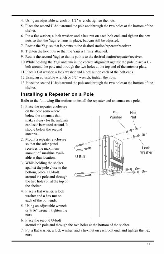
Installing a Repeater on a PoleRefer to the following illustrations to install the repeater and antennas on a pole:
1. Place the repeater enclosure on the pole somewhere below the antennas that makes it easy for the antenna cables to be routed around. It should below the second antenna.
2. Mount a repeater enclosure so that the solar panel receives the maximum amount of sunshine avail-able at that location.
3. While holding the shelter against the pole close to the bottom, place a U-bolt around the pole and through the two holes on at the top of the shelter.
4. Place a flat washer, a lock washer and a hex nut on each of the bolt ends.
5. Using an adjustable wrench or 7/16" wrench, tighten the nuts.
6. Place the second U-bolt around the pole and through the two holes at the bottom of the shelter.
7. Put a flat washer, a lock washer, and a hex nut on each bolt end, and tighten the hex nuts.
Flat Washer
Lock Washer
HexNut
U-Bolt
12
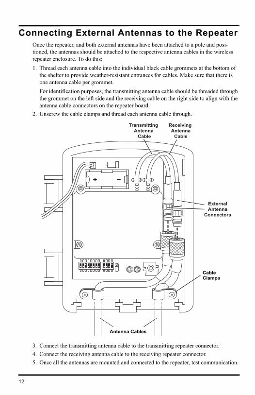
Connecting External Antennas to the RepeaterOnce the repeater, and both external antennas have been attached to a pole and posi-tioned, the antennas should be attached to the respective antenna cables in the wireless repeater enclosure. To do this:
1. Thread each antenna cable into the individual black cable grommets at the bottom of the shelter to provide weather-resistant entrances for cables. Make sure that there is one antenna cable per grommet.
For identification purposes, the transmitting antenna cable should be threaded through the grommet on the left side and the receiving cable on the right side to align with the antenna cable connectors on the repeater board.
2. Unscrew the cable clamps and thread each antenna cable through.
3. Connect the transmitting antenna cable to the transmitting repeater connector.
4. Connect the receiving antenna cable to the receiving repeater connector.
5. Once all the antennas are mounted and connected to the repeater, test communication.
Antenna Cables
CableClamps
Receiving Antenna
Cable
Transmitting Antenna
Cable
ExternalAntenna
Connectors
13
SpecificationsComplete specifications for all of the Vantage Pro2 weather products as well as the wire-less repeater are available in the Weather Support section of our website:
http://www.davisnet.com/support/weather/
GeneralOperating Temperature. . . . . . . . . . . . . . -40 to 150° Fahrenheit (-40 to 65° Celsius)Non-Operating Temperature . . . . . . . . . . -40 to 150° Fahrenheit (-40 to 65° Celsius)Current Draw . . . . . . . . . . . . . . . . . . . . . 1.5 mA at 4-6 VDC (average draw when not in
Test Mode)Batteries . . . . . . . . . . . . . . . . . . . . . . . . .CR 123A 3-volt lithium battery Battery Life Estimates (with no solar or AC power input):
*Both received directly by the repeater and those IDs repeated from the previous repeater in a chain.
Note: Battery life in excess of two years is expected with normal solar input.
Solar Panel . . . . . . . . . . . . . . . . . . . . . . . 0.5 WattsAlternate Power . . . . . . . . . . . . . . . . . . .AC power adapterHousing Material . . . . . . . . . . . . . . . . . . .UV-resistant PVC plasticDimensions . . . . . . . . . . . . . . . . . . . . . . . 6.25'' x 2.25” x 7.88'' (159 mm x 57 mm x 200 mm)Weight. . . . . . . . . . . . . . . . . . . . . . . . . . . 1.188 lb. (.539 kg)
# of IDs* Estimated Life Expectancy (Months)
1 4
4 1.5
8 <1
14
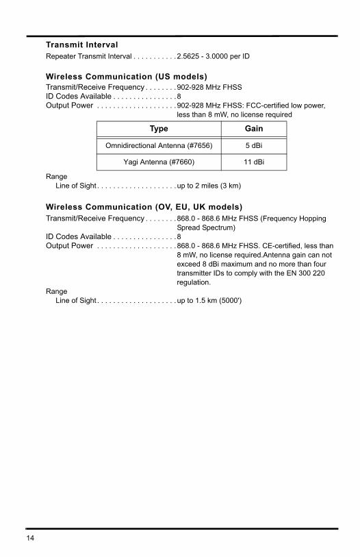
Transmit IntervalRepeater Transmit Interval . . . . . . . . . . . 2.5625 - 3.0000 per ID
Wireless Communication (US models)Transmit/Receive Frequency . . . . . . . . 902-928 MHz FHSSID Codes Available . . . . . . . . . . . . . . . .8Output Power . . . . . . . . . . . . . . . . . . . . 902-928 MHz FHSS: FCC-certified low power,
less than 8 mW, no license required
RangeLine of Sight . . . . . . . . . . . . . . . . . . . . up to 2 miles (3 km)
Wireless Communication (OV, EU, UK models)Transmit/Receive Frequency . . . . . . . . 868.0 - 868.6 MHz FHSS (Frequency Hopping
Spread Spectrum)ID Codes Available . . . . . . . . . . . . . . . .8Output Power . . . . . . . . . . . . . . . . . . . . 868.0 - 868.6 MHz FHSS. CE-certified, less than
8 mW, no license required.Antenna gain can not exceed 8 dBi maximum and no more than four transmitter IDs to comply with the EN 300 220 regulation.
RangeLine of Sight . . . . . . . . . . . . . . . . . . . . up to 1.5 km (5000')
Type Gain
Omnidirectional Antenna (#7656) 5 dBi
Yagi Antenna (#7660) 11 dBi