Embed Size (px)
Citation preview
1062 OPTICS LETTERS / Vol. 20, No. 9 / May 1, 1995
Long-distance frequency-division interferometerfor communication and quantum cryptography
P. C. Sun, Y. Mazurenko,* and Y. Fainman
Department of Electrical and Computer Engineering, University of California, San Diego, MC-0407, La Jolla, California 92093
Received December 5, 1994
We introduce and demonstrate experimentally a single-channel long-distance interferometer that utilizes fre-quency division of two optical waves by using acousto-optic devices at the transmitting and receiving nodesof the interferometer. This novel single-channel long-distance interferometer provides unity visibility of theinterference and therefore is useful not only for remote sensing and optical communications but also for quantumcryptosystems applications.
A long-distance interferometer (LDI) is a device thatprovides interferometric interaction between trans-mitter and receiver nodes in remote locations. Itallows a phase information coded beam and the refer-ence beam from a transmitter node to be transmittedto a remote receiver node. For practical considera-tions, to ensure preservation of the fields’ coherenceproperties that are necessary for detection it is de-sirable to use a single long-distance channel, in whichthe two optical fields are multiplexed and demulti-plexed at the transmitter and the receiver nodes.1,2
LDI’s have been used for high-sensitivity detec-tion of phase information in physical processes thatoccur in a remote location2 as well as for opticalcommunication network applications.1 Another ap-plication of a single-channel LDI is in secure op-tical communication that uses such principles ofquantum cryptography3,4 as polarization encoding(division) or time division5,6 or a combination of po-larization division and time division.7,8 The quan-tum cryptosystems5 – 8 use LDI’s for the transmissionof single photons. The states of the photons are se-lected randomly at the transmitting node from twoconjugated bases by the use of orthonomal polariza-tions or phases, and at the receiving node one ofthese two conjugated bases is again selected at ran-dom for detection. When the selection of the basisat the receiver matches that used by the transmitter,the detection corresponds to probability 1; when thebases mismatch, the detection corresponds to proba-bility 1/2. A prearranged protocol is used for trans-lation of encrypted signals through an open channel.Operators at the transmitter and the receiver nodesdevelop a sequence of codes that can be used later forsecret key encryption. The implementation of thequantum crypotosystem relies on the ability to de-tect single-photon interference effects. Inasmuch asfor each photon the observation can be realized onlyonce, a LDI with unity visibility of interference pat-tern is necessary to ensure that when one of the twoconjugated bases at the receiver is selected correctlythe detection will correspond to probability 1.
The existing techniques of implementing LDI’s usetime division, coherence division, or polarization di-vision of two beams in a single communication chan-
0146-9592/95/091062-03$6.00/0
nel. In the case of coherence division or time divi-sion a LDI can be realized by use of two unbalancedMach–Zehnder devices communicating via a singletransmission channel. The device at the transmit-ter node creates a time delay between the two beamsthat is greater than the coherence time1,2 or thepulse duration5,6 of the radiation. The device at thereceiver node compensates for this time delay fortwo of the total of four optical signals and createstheir interference at the output. For the coherence-division technique, because of the inevitable existenceof a noninterfering signal the maximum visibility ofinterference is 1/2, which is nevertheless sufficientfor remote sensing and communications. However,for the time-division LDI, interference with unityvisibility can be obtained by use of time-resolved(time-gated) detection to isolate the two interferingoptical signals from the two noninterfering signals.5,6
A combination of time division and polarization di-vision has been used to achieve high photon trans-mission efficiency,7,8 which is important for quantumcryptography applications.
In this Letter we introduce a novel single-channelLDI that achieves frequency division of two opti-cal waves by the use of acousto-optic devices inthe transmitting and receiving nodes. Our single-communication-channel LDI provides unity visibilityof the interference pattern and thereby is useful notonly for remote sensing and optical communicationbut also for quantum cryptosystems applications.Frequency shift of radiation was used earlier in aLDI to provide heterodyne detection2; however, inthis case unity fringe visibility can never be reached.
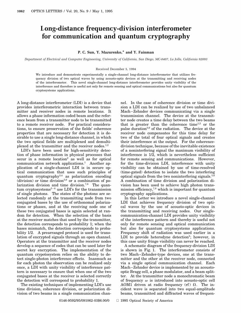
A schematic diagram of the frequency-division LDIis shown in Fig. 1. The interferometer consists oftwo Mach–Zehnder-type devices, one at the trans-mitter and the other at the receiver node, connectedvia a single optical communication channel. EachMach–Zehnder device is implemented by an acousto-optic Bragg cell, a phase modulator, and a beam split-ter. At the transmitter node a monochromatic beamof frequency v is introduced into acousto-optic cellAOM1 driven at radio frequency (rf ) V. The in-cident wave is separated into two equal-amplitudebeams, transmitted and diffracted waves of frequen-
1995 Optical Society of America
May 1, 1995 / Vol. 20, No. 9 / OPTICS LETTERS 1063
Fig. 1. Schematic diagram of the frequency-division long-distance interferometer. M’s, mirrors.
cies v and v 1 V, respectively. The diffracted beamis transmitted through a phase modulator, PM1, tointroduce a transmitter phase shift fA (this phaseshift can also be introduced through the rf of AOM1).The transmitted and the diffracted waves propagatethrough different paths and are combined by beamsplitter BS1 to implement frequency division. Theresultant single two-frequency beam can be intro-duced into a long-distance optical communication linkfor transmission to the receiver node.
At the receiver node the beam from the communi-cation channel is separated by beam splitter BS2 intotwo beams for demultiplexing and detection. Thesetwo beams, each containing waves at two optical fre-quencies, v and v 1 V, propagate through differ-ent paths, where one of the beams is transmittedthrough phase modulator PM2 to introduce the re-ceiver phase shift fB (again, this phase shift canalso be introduced via the rf of AOM2). Finally thetwo beams are combined by receiver acousto-opticcell AOM2 where each of the two incident beams isseparated into equal-amplitude transmitted and dif-fracted waves. The two beams entering AOM2 needto be aligned such that the diffracted beam of onepropagates in the direction of the transmitted beamof the other. Depending on the mutual direction ofthe two incident beams and the direction of propaga-tion of the sound wave in AOM2, the diffracted beamswill experience a frequency shift of V or 2V. The re-sultant output beams 1 and 2 will contain frequencysignals of v 2 V, v, v 1 V and v, v 1 V, v 1 2V,respectively (see Fig. 1). Note that for precise com-
pensation of the frequency shifts both the transmitterand the receiver acousto-optic cells need to be drivenat the same rf, V.
After demultiplexing, only the waves of frequencyv in beam 1 and that of frequency v 1 V in beam2 can produce interference signals. These two in-terference signals in beams 1 and 2 result from thesuperposition of optical fields that propagate throughpath AOM1, M1, BS1, BS2, PM2, AOM2 and throughpath AOM1, PM1, BS1, BS2, M2, AOM2, respec-tively. The resultant interference signals depend onthe phase difference fA 2 fB, controlled by both PM1and PM2, and therefore the transmitted informationcan be demodulated. These two output interferencesignals at frequencies v and v 1 V are mutuallycomplementary, similar to these of the conventionaldouble-beam interferometer. In general, the twointerference signals may be detected with two pho-todetectors, D1 and D2, but the maximum interfer-ence fringe visibility of such an interferometer will belimited to 1/2 because the presence of noninterferingfrequency components. However, it is possible toachieve unity fringe visibility for the two interferingsignals at frequencies v and v 1 V by use of narrow-band optical frequency filters F svd and F sv 1 Vd,respectively (see Fig. 1). Using monochromaticradiation and frequency division with frequency se-lection, as introduced in our LDI described above, isanalogous to using short optical pulses and time gat-ing in the LDI’s with time division. Note that theintroduced LDI can also be operated with a chaoticlight source with a frequency bandwidth much larger
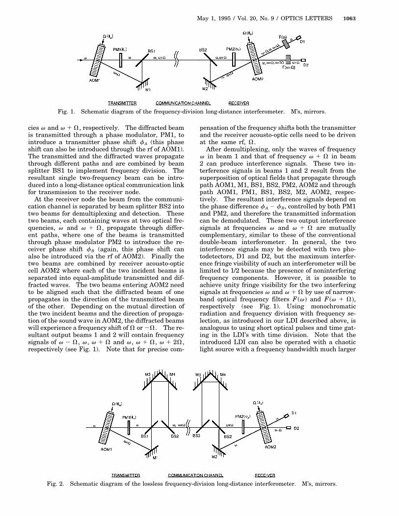
Fig. 2. Schematic diagram of the lossless frequency-division long-distance interferometer. M’s, mirrors.
1064 OPTICS LETTERS / Vol. 20, No. 9 / May 1, 1995
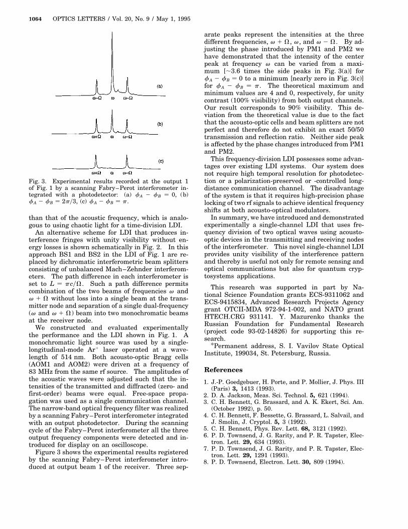
Fig. 3. Experimental results recorded at the output 1of Fig. 1 by a scanning Fabry–Perot interferometer in-tegrated with a photodetector: (a) fA 2 fB 0, (b)fA 2 fB 2py3, (c) fA 2 fB p.
than that of the acoustic frequency, which is analo-gous to using chaotic light for a time-division LDI.
An alternative scheme for LDI that produces in-terference fringes with unity visibility without en-ergy losses is shown schematically in Fig. 2. In thisapproach BS1 and BS2 in the LDI of Fig. 1 are re-placed by dichromatic interferometric beam splittersconsisting of unbalanced Mach–Zehnder interferom-eters. The path difference in each interferometer isset to L pcyV. Such a path difference permitscombination of the two beams of frequencies v andv 1 V without loss into a single beam at the trans-mitter node and separation of a single dual-frequency(v and v 1 V) beam into two monochromatic beamsat the receiver node.
We constructed and evaluated experimentallythe performance and the LDI shown in Fig. 1. Amonochromatic light source was used by a single-longitudinal-mode Ar1 laser operated at a wave-length of 514 nm. Both acousto-optic Bragg cells(AOM1 and AOM2) were driven at a frequency of83 MHz from the same rf source. The amplitudes ofthe acoustic waves were adjusted such that the in-tensities of the transmitted and diffracted (zero- andfirst-order) beams were equal. Free-space propa-gation was used as a single communication channel.The narrow-band optical frequency filter was realizedby a scanning Fabry–Perot interferometer integratedwith an output photodetector. During the scanningcycle of the Fabry–Perot interferometer all the threeoutput frequency components were detected and in-troduced for display on an oscilloscope.
Figure 3 shows the experimental results registeredby the scanning Fabry–Perot interferometer intro-duced at output beam 1 of the receiver. Three sep-
arate peaks represent the intensities at the threedifferent frequencies, v 1 V, v, and v 2 V. By ad-justing the phase introduced by PM1 and PM2 wehave demonstrated that the intensity of the centerpeak at frequency v can be varied from a maxi-mum [,3.6 times the side peaks in Fig. 3(a)] forfA 2 fB 0 to a minimum [nearly zero in Fig. 3(c)]for fA 2 fB p. The theoretical maximum andminimum values are 4 and 0, respectively, for unitycontrast (100% visibility) from both output channels.Our result corresponds to 90% visibility. This de-viation from the theoretical value is due to the factthat the acousto-optic cells and beam splitters are notperfect and therefore do not exhibit an exact 50/50transmission and reflection ratio. Neither side peakis affected by the phase changes introduced from PM1and PM2.
This frequency-division LDI possesses some advan-tages over existing LDI systems. Our system doesnot require high temporal resolution for photodetec-tion or a polarization-preserved or -controlled long-distance communication channel. The disadvantageof the system is that it requires high-precision phaselocking of two rf signals to achieve identical frequencyshifts at both acousto-optical modulators.
In summary, we have introduced and demonstratedexperimentally a single-channel LDI that uses fre-quency division of two optical waves using acousto-optic devices in the transmitting and receiving nodesof the interferometer. This novel single-channel LDIprovides unity visibility of the interference patternand thereby is useful not only for remote sensing andoptical communications but also for quantum cryp-tosystems applications.
This research was supported in part by Na-tional Science Foundation grants ECS-9311062 andECS-9415834, Advanced Research Projects Agencygrant OTCII-MDA 972-94-1-002, and NATO grantHTECH.CRG 931141. Y. Mazurenko thanks theRussian Foundation for Fundamental Research(project code 93-02-14826) for supporting this re-search.
*Permanent address, S. I. Vavilov State OpticalInstitute, 199034, St. Petersburg, Russia.
References
1. J.-P. Goedgebuer, H. Porte, and P. Mollier, J. Phys. III(Paris) 3, 1413 (1993).
2. D. A. Jackson, Meas. Sci. Technol. 5, 621 (1994).3. C. H. Bennett, G. Brassard, and A. K. Ekert, Sci. Am.
(October 1992), p. 50.4. C. H. Bennett, F. Bessette, G. Brassard, L. Salvail, and
J. Smolin, J. Cryptol. 5, 3 (1992).5. C. H. Bennett, Phys. Rev. Lett. 68, 3121 (1992).6. P. D. Townsend, J. G. Rarity, and P. R. Tapster, Elec-
tron. Lett. 29, 634 (1993).7. P. D. Townsend, J. G. Rarity, and P. R. Tapster, Elec-
tron. Lett. 29, 1291 (1993).8. P. D. Townsend, Electron. Lett. 30, 809 (1994).