Embed Size (px)
Citation preview
Long-Baseline Neutrino Experiment (LBNE) Project Conceptual Design Report
Volume 6: Conventional Facilities at the Far Site
March 13, 2012
i
Contents
Contents ....................................................................................................................................... i
Acronyms and Abbreviations .................................................................................................... v
List of Figures ........................................................................................................................... vii
List of Tables .............................................................................................................................. ix
1 Introduction ...................................................................................................................... 1-1
1.1 Introduction to LBNE .................................................................................................. 1-1
1.1.1 About this Conceptual Design Report .................................................................... 1-1
1.1.2 LBNE and the U.S. Neutrino-Physics Program ...................................................... 1-2
1.1.3 LBNE Project Organization .................................................................................... 1-3
1.1.4 Principal Parameters of the LBNE Project ............................................................. 1-3
1.1.5 Supporting Documents ........................................................................................... 1-3
1.2 Introduction to LBNE Conventional Facilities at the Far Site ...................................... 1-4
1.3 Participants................................................................................................................. 1-6
1.4 Codes and Standards................................................................................................. 1-6
2 Existing Site Conditions .................................................................................................. 2-8
2.1 Existing Site Conditions ............................................................................................ 2-12
2.1.1 Existing Facilities and Site Assessment ............................................................... 2-12
2.2 Geology and Existing Excavations ........................................................................... 2-16
2.2.1 Geologic Setting ................................................................................................... 2-17
2.2.2 Rock Mass Characterization ................................................................................ 2-17
2.2.3 Geologic Conclusions ........................................................................................... 2-20
3 The Facility Layout ......................................................................................................... 3-21
3.1 Surface Infrastructure (WBS 130.06.05.05.02.02.01) .............................................. 3-23
3.1.1 Roads and Access ............................................................................................... 3-23
3.1.2 Electrical Infrastructure ......................................................................................... 3-24
3.1.3 Cyberinfrastructure ............................................................................................... 3-25
3.1.4 Mechanical and HVAC ......................................................................................... 3-26
3.1.5 Plumbing Systems ................................................................................................ 3-26
ii
3.2 Project-Wide Considerations .................................................................................... 3-30
3.2.1 Environmental Protection ..................................................................................... 3-30
3.2.2 Safeguards and Security ...................................................................................... 3-31
3.2.3 Emergency Shelter Provisions ............................................................................. 3-32
3.2.4 Energy Conservation ............................................................................................ 3-32
3.2.5 DOE Space Allocation .......................................................................................... 3-32
4 Surface Buildings ........................................................................................................... 4-33
4.1 Ross Headframe and Hoist Buildings (WBS 130.06.05.05.02.04.02) ..................... 4-33
4.1.1 Architectural ......................................................................................................... 4-34
4.1.2 Structural .............................................................................................................. 4-34
4.1.3 Mechanical ........................................................................................................... 4-35
4.1.4 Electrical ............................................................................................................... 4-35
4.1.5 Plumbing .............................................................................................................. 4-35
4.1.6 ES&H .................................................................................................................... 4-35
4.2 Ross Crusher Building .............................................................................................. 4-35
4.3 Ross Dry................................................................................................................... 4-36
4.4 Yates Headframe and Hoist Building (WBS 130.06.05.05.02.03.02) ....................... 4-37
4.4.1 Civil ....................................................................................................................... 4-38
4.4.2 Architectural ......................................................................................................... 4-39
4.4.3 Structural .............................................................................................................. 4-39
4.4.4 Mechanical and Plumbing .................................................................................... 4-39
4.4.5 Electrical ............................................................................................................... 4-40
4.5 Temporary Warehouse Space ................................................................................. 4-40
5 Underground Excavation (WBS 130.06.05.05.04) ........................................................ 5-41
5.1 LAr Cavity (WBS 130.06.05.05.04.02) ..................................................................... 5-42
5.1.1 Structural and Cranes .......................................................................................... 5-45
5.2 LAr-FD Upper Cavity ................................................................................................ 5-46
5.3 Access/Egress Drifts (WBS 130.06.05.05.04.01) ..................................................... 5-46
5.4 Interfaces between LAr-FD and Excavation ............................................................. 5-46
6 Underground Infrastructure (WBS 130.06.05.05.03) .................................................. 6-47
6.1 Fire/Life Safety Systems (WBS 130.06.05.05.03.05) ............................................... 6-48
6.1.1 Egress and Areas of Refuge ................................................................................ 6-48
6.1.2 Emergency Systems ............................................................................................ 6-48
6.2 Shafts and Hoists (WBS 130.06.05.05.05) ............................................................... 6-49
6.2.1 Ross Shaft ............................................................................................................ 6-50
iii
6.2.2 Yates Shaft ........................................................................................................... 6-51
6.3 Ventilation (WBS 130.06.05.05.03.02) ..................................................................... 6-54
6.3.1 Ventilation and Utility Borehole ............................................................................ 6-55
6.4 Electrical (WBS 130.06.05.05.03.04) ....................................................................... 6-56
6.4.1 Normal Power ....................................................................................................... 6-56
6.4.2 Standby Power ..................................................................................................... 6-57
6.4.3 Fire Alarm and Detection ...................................................................................... 6-57
6.4.4 Lighting ................................................................................................................. 6-58
6.4.5 Grounding ............................................................................................................. 6-58
6.5 Plumbing (WBS 130.06.05.05.03.03) ....................................................................... 6-58
6.5.1 Potable Water ....................................................................................................... 6-59
6.5.2 Industrial Water .................................................................................................... 6-59
6.5.3 Fire Suppression .................................................................................................. 6-59
6.5.4 Drainage ............................................................................................................... 6-60
6.5.5 Sanitary Drainage ................................................................................................. 6-60
6.5.6 Chilled Water ........................................................................................................ 6-60
6.6 Cyberinfrastructure (WBS 130.06.05.05.03.01) ....................................................... 6-61
6.7 Waste Rock Handling (WBS 130.06.05.05.03.07) ................................................... 6-61

v
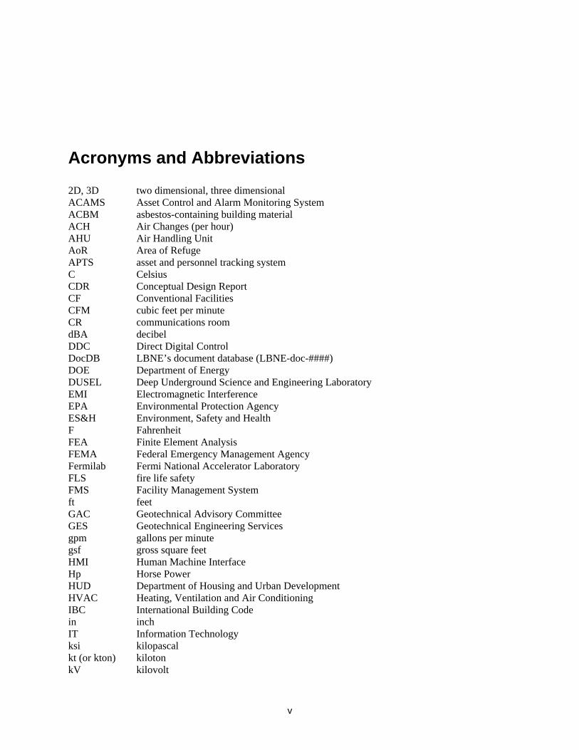
Acronyms and Abbreviations
2D, 3D two dimensional, three dimensional ACAMS Asset Control and Alarm Monitoring System ACBM asbestos-containing building material ACH Air Changes (per hour) AHU Air Handling Unit AoR Area of Refuge APTS asset and personnel tracking system C Celsius CDR Conceptual Design Report CF Conventional Facilities CFM cubic feet per minute CR communications room dBA decibel DDC Direct Digital Control DocDB LBNE’s document database (LBNE-doc-####) DOE Department of Energy DUSEL Deep Underground Science and Engineering Laboratory EMI Electromagnetic Interference EPA Environmental Protection Agency ES&H Environment, Safety and Health F Fahrenheit FEA Finite Element Analysis FEMA Federal Emergency Management Agency Fermilab Fermi National Accelerator Laboratory FLS fire life safety FMS Facility Management System ft feet GAC Geotechnical Advisory Committee GES Geotechnical Engineering Services gpm gallons per minute gsf gross square feet HMI Human Machine Interface Hp Horse Power HUD Department of Housing and Urban Development HVAC Heating, Ventilation and Air Conditioning IBC International Building Code in inch IT Information Technology ksi kilopascal kt (or kton) kiloton kV kilovolt
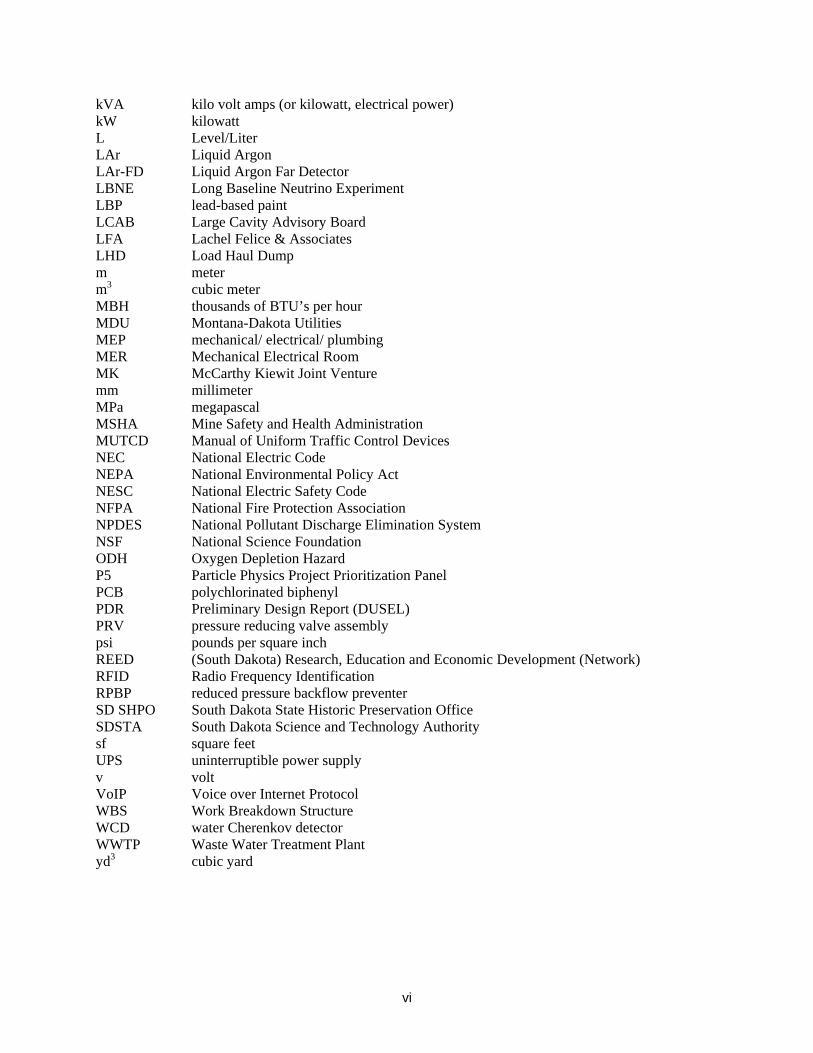
vi
kVA kilo volt amps (or kilowatt, electrical power) kW kilowatt L Level/Liter LAr Liquid Argon LAr-FD Liquid Argon Far Detector LBNE Long Baseline Neutrino Experiment LBP lead-based paint LCAB Large Cavity Advisory Board LFA Lachel Felice & Associates LHD Load Haul Dump m meter m3 cubic meter MBH thousands of BTU’s per hour MDU Montana-Dakota Utilities MEP mechanical/ electrical/ plumbing MER Mechanical Electrical Room MK McCarthy Kiewit Joint Venture mm millimeter MPa megapascal MSHA Mine Safety and Health Administration MUTCD Manual of Uniform Traffic Control Devices NEC National Electric Code NEPA National Environmental Policy Act NESC National Electric Safety Code NFPA National Fire Protection Association NPDES National Pollutant Discharge Elimination System NSF National Science Foundation ODH Oxygen Depletion Hazard P5 Particle Physics Project Prioritization Panel PCB polychlorinated biphenyl PDR Preliminary Design Report (DUSEL) PRV pressure reducing valve assembly psi pounds per square inch REED (South Dakota) Research, Education and Economic Development (Network) RFID Radio Frequency Identification RPBP reduced pressure backflow preventer SD SHPO South Dakota State Historic Preservation Office SDSTA South Dakota Science and Technology Authority sf square feet UPS uninterruptible power supply v volt VoIP Voice over Internet Protocol WBS Work Breakdown Structure WCD water Cherenkov detector WWTP Waste Water Treatment Plant yd3 cubic yard
vii
List of Figures
Figure 1-1: Location of LAr-FD at 4850L. [Dangermond Keane Architecture, Courtesy Sanford Laboratory] ................................................................................................................................. 1-5
Figure 2-1: Regional Context showing the city of Lead, South Dakota. [Dangermond Keane Architecture, Courtesy Sanford Laboratory] ............................................................................... 2-9
Figure 2-2: Sanford Laboratory Complex shown in the context of the city of Lead, South Dakota, and the property remaining under ownership of Barrick. Area shown in yellow is a potential future expansion of the SDSTA property. [Dangermond Keane Architecture, Courtesy of Sanford Laboratory] ................................................................................................................. 2-10
Figure 2-3: Sanford Laboratory Yates Campus shown on the left and Kirk Canyon to the right. [Courtesy of Sanford Laboratory] ............................................................................................. 2-11
Figure 2-4: Aerial view of Sanford Laboratory (boundary in red) and the adjacent city of Lead. [Dangermond Keane Architecture, Courtesy of Sanford Laboratory] ...................................... 2-11
Figure 2-5: Historic photo of milling operation, Yates Headframe, Hoist, and Foundry. [Courtesy Homestake Adams Research and Cultural Center] ................................................................. 2-15
Figure 2-6: Map of Lead Historic District. [Dangermond Keane Architecture, Courtesy of Sanford Laboratory] ............................................................................................................................... 2-16
Figure 2-7: General geologic map at the 4850L and location of drill holes. [Golder Associates, Courtesy Sanford Laboratory] .................................................................................................. 2-19
Figure 3-1: Architectural Site Plan. [HDR] ............................................................................... 3-21
Figure 3-2: Yate Complex Architectural Site Plan. [HDR] ........................................................ 3-22
Figure 3-3: Ross Complex Architectural Site Plan. [HDR] ....................................................... 3-22
Figure 3-4: Oro Hondo Complex Architectural Site Plan. [HDR] .............................................. 3-23
Figure 3-5: Supply Power for LAr-FD at 4850L. [HDR] ............................................................ 3-24
Figure 3-6: Yates Complex civil site plan including water distribution system. [HDR] ............. 3-27
Figure 3-7: Ross Complex civil site plan. [HDR] ...................................................................... 3-28
Figure 3-8: Depiction of what the pipe conveyor will look like to the Lead, SD community. [SRK, Courtesy Sanford Laboratory] .................................................................................................. 3-31
Figure 4-1: Photo of Ross Hoist exterior. [HDR] ...................................................................... 4-33
Figure 4-2: Photo of Ross Headframe. [HDR] ......................................................................... 4-34
Figure 4-3: Photo of Ross Crusher exterior. [HDR] ................................................................. 4-36
Figure 4-4: Photo of Ross Dry Exterior. [HDR] ........................................................................ 4-37
Figure 4-5: Location of new Command and Control Center. [HDR] ......................................... 4-37
viii
Figure 4-6: Photo of Yates Headframe exterior. [HDR] ........................................................... 4-38
Figure 4-7: Photo of Yates Headframe interior. [HDR] ............................................................ 4-38
Figure 4-8: Layout of fire pump and AHUs in Yates Headframe. [HDR] .................................. 4-39
Figure 5-1: Spaces required for LAr-FD at 4850L (Yates AoR not shown for clarity). [Golder Associates] ............................................................................................................................... 5-41
Figure 5-2: Spaces required for LAr-FD on the 3650L. [Golder Associates] ........................... 5-42
Figure 5-3: Dimensions of the 33kT detector. The lower section is 395’(121m) long, while the upper portion is 527’ (161m) long. [Golder Associates] ........................................................... 5-43
Figure 5-4: LAr-FD Cavity Excavation Sequence. [Golder Associates] ................................... 5-44
Figure 5-5: LAr-FD Cavity ground support. [Golder Associates] .............................................. 5-45
Figure 6-1: Life Safety Systems for LAr-FD at 4850L. [Arup] .................................................. 6-49
Figure 6-2: Ross Shaft, typical shaft set. [SRK, Courtesy Sanford Laboratory] ....................... 6-50
Figure 6-3: Existing Yates Shaft layout. [Adapted from SRK, Courtesy Sanford Laboratory] .. 6-53
Figure 6-4: Preliminary Yates Shaft design layout. [Sanford Laboratory] ................................ 6-53
Figure 6-5: Ventilation flow diagram (ventilation path shown with red arrows). [Arup]............. 6-55
Figure 6-6: Waste Rock Handling System route. [Dangermond Keane Architecture, Courtesy Sanford Laboratory] ................................................................................................................. 6-63
ix
List of Tables
Table 1-1: LBNE Principal Parameters. ..................................................................................... 1-3
Table 1-2: LBNE CD-1 Documents. ........................................................................................... 1-4
Table 3-1: Electrical Load Table. ............................................................................................. 3-25
Table 6-1: Environmental Design Criteria. [Arup] .................................................................... 6-55

Chapter 1: Introduction 1-1
LBNE Conceptual Design Report
1 Introduction
1.1 Introduction to LBNE
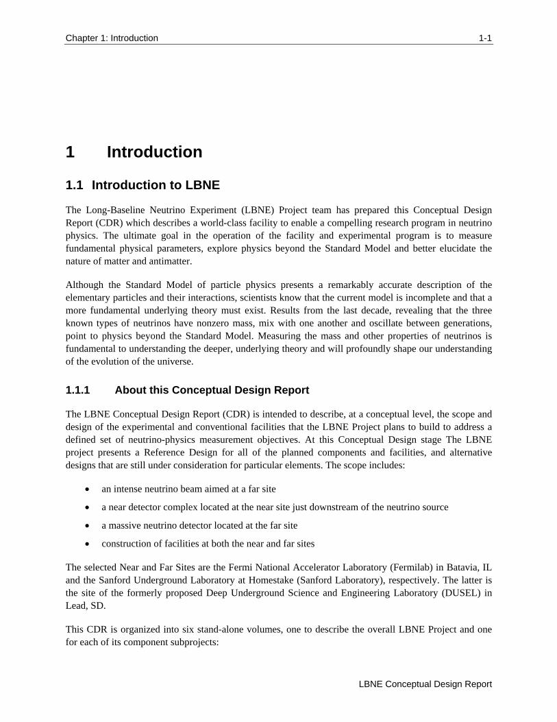
The Long-Baseline Neutrino Experiment (LBNE) Project team has prepared this Conceptual Design Report (CDR) which describes a world-class facility to enable a compelling research program in neutrino physics. The ultimate goal in the operation of the facility and experimental program is to measure fundamental physical parameters, explore physics beyond the Standard Model and better elucidate the nature of matter and antimatter.
Although the Standard Model of particle physics presents a remarkably accurate description of the elementary particles and their interactions, scientists know that the current model is incomplete and that a more fundamental underlying theory must exist. Results from the last decade, revealing that the three known types of neutrinos have nonzero mass, mix with one another and oscillate between generations, point to physics beyond the Standard Model. Measuring the mass and other properties of neutrinos is fundamental to understanding the deeper, underlying theory and will profoundly shape our understanding of the evolution of the universe.
1.1.1 About this Conceptual Design Report
The LBNE Conceptual Design Report (CDR) is intended to describe, at a conceptual level, the scope and design of the experimental and conventional facilities that the LBNE Project plans to build to address a defined set of neutrino-physics measurement objectives. At this Conceptual Design stage The LBNE project presents a Reference Design for all of the planned components and facilities, and alternative designs that are still under consideration for particular elements. The scope includes:
an intense neutrino beam aimed at a far site
a near detector complex located at the near site just downstream of the neutrino source
a massive neutrino detector located at the far site
construction of facilities at both the near and far sites
The selected Near and Far Sites are the Fermi National Accelerator Laboratory (Fermilab) in Batavia, IL and the Sanford Underground Laboratory at Homestake (Sanford Laboratory), respectively. The latter is the site of the formerly proposed Deep Underground Science and Engineering Laboratory (DUSEL) in Lead, SD.
This CDR is organized into six stand-alone volumes, one to describe the overall LBNE Project and one for each of its component subprojects:
1-2 Chapter 1: Introduction
Volume 6: LBNE Conventional Facilities at the Far Site
Volume 1: The LBNE Project
Volume 2: The Beamline at the Near Site
Volume 3: Detectors at the Near Site
Volume 4: The Liquid Argon Detector at the Far Site
Volume 5: Conventional Facilities at the Near Site
Volume 6: Conventional Facilities at the Far Site
Volume 1 is intended to provide readers of varying backgrounds an introduction to LBNE and to the following volumes of this CDR. It contains high-level information and refers the reader to topic-specific volumes and supporting documents, listed in Section 1.1.5. Each of the other volumes contains a common, brief introduction to the overall LBNE Project, an introduction to the individual subproject, and a detailed description of its conceptual design.
1.1.2 LBNE and the U.S. Neutrino-Physics Program
In its 2008 report, the Particle Physics Project Prioritization Panel (P5) recommended a world-class neutrino-physics program as a core component of the U.S. particle physics program [1]. Included in the report is the long-term vision of a large detector at the Sanford Laboratory and a high-intensity neutrino source at Fermilab.
On January 8, 2010, the Department of Energy (DOE) approved the Mission Need for a new long-baseline neutrino experiment that would enable this world-class program and firmly establish the U.S. as the leader in neutrino science. The LBNE Project is designed to meet this Mission Need.
With the facilities provided by the LBNE Project, the LBNE Science Collaboration proposes to mount a broad attack on the science of neutrinos with sensitivity to all known parameters in a single experiment. The focus of the program will be the explicit demonstration of leptonic CP violation, if it exists, by precisely measuring the asymmetric oscillations of muon-type neutrinos and antineutrinos into electron-type neutrinos and antineutrinos.
The experiment will result in the most precise measurements of the three-flavor neutrino-oscillation parameters over a very long baseline and a wide range of neutrino energies, in particular, the CP-violating phase in the three-flavor framework. The unique features of the experiment – the long baseline, the broad-band beam, and the high resolution of the detector – will enable the search for new physics that manifests itself as deviations from the expected three-flavor neutrino-oscillation model.
The configuration of the LBNE facility, in which a large neutrino detector is located deep underground, could also provide opportunities for research in other areas of physics, such as nucleon decay and neutrino astrophysics, including studies of neutrino bursts from supernovae occurring in our galaxy. The scientific goals and capabilities of LBNE are outlined in Volume 1 of this CDR and described fully in the LBNE Case Study Report (Liquid Argon TPC Far Detector) [2], and the 2010 Interim report of the Long-Baseline Neutrino Experiment Collaboration Physics Working Groups [3].
Chapter 1: Introduction 1-3
LBNE Conceptual Design Report
1.1.3 LBNE Project Organization
The LBNE Project Office at Fermilab is headed by the Project Manager and assisted by the Project Engineer, Project Systems Engineer, and Project Scientist. Project Office support staff include a Project Controls Manager and supporting staff, a Financial Manager, an Environment, Safety and Health (ES&H) Manager, a Computing Coordinator, Quality Assurance and Risk Managers, a documentation team and administrative support.
The Beamline, Liquid Argon Far Detector and Conventional Facilities subprojects are managed by the Project Office at Fermilab, while the Near Detector Complex subproject is managed by a Project Office at Los Alamos National Laboratory.
More information on Project Organization can be found in Volume 1 of this CDR. A full description of LBNE Project management is contained in the LBNE Project Management Plan [4].
1.1.4 Principal Parameters of the LBNE Project
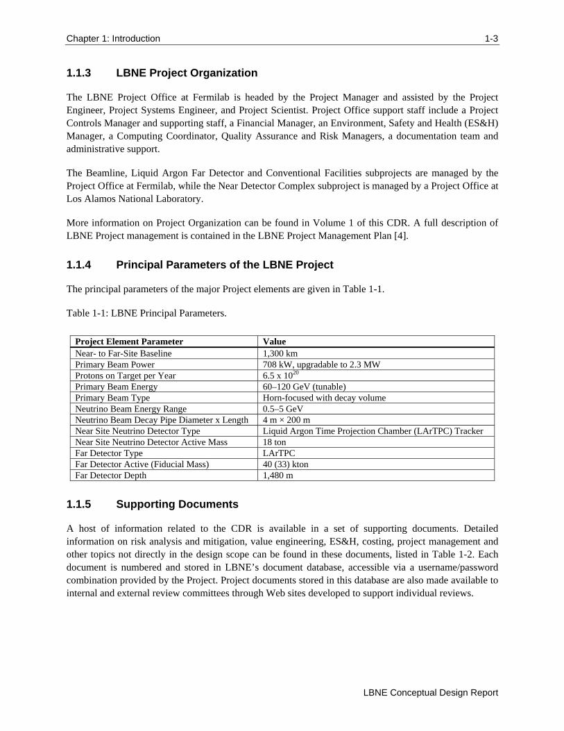
The principal parameters of the major Project elements are given in Table 1-1.
Table 1-1: LBNE Principal Parameters.
Project Element Parameter Value Near- to Far-Site Baseline 1,300 km Primary Beam Power 708 kW, upgradable to 2.3 MW Protons on Target per Year 6.5 x 10²⁰ Primary Beam Energy 60–120 GeV (tunable) Primary Beam Type Horn-focused with decay volume Neutrino Beam Energy Range 0.5–5 GeV Neutrino Beam Decay Pipe Diameter x Length 4 m × 200 m Near Site Neutrino Detector Type Liquid Argon Time Projection Chamber (LArTPC) Tracker Near Site Neutrino Detector Active Mass 18 ton Far Detector Type LArTPC Far Detector Active (Fiducial Mass) 40 (33) kton Far Detector Depth 1,480 m
1.1.5 Supporting Documents
A host of information related to the CDR is available in a set of supporting documents. Detailed information on risk analysis and mitigation, value engineering, ES&H, costing, project management and other topics not directly in the design scope can be found in these documents, listed in Table 1-2. Each document is numbered and stored in LBNE’s document database, accessible via a username/password combination provided by the Project. Project documents stored in this database are also made available to internal and external review committees through Web sites developed to support individual reviews.
1-4 Chapter 1: Introduction
Volume 6: LBNE Conventional Facilities at the Far Site
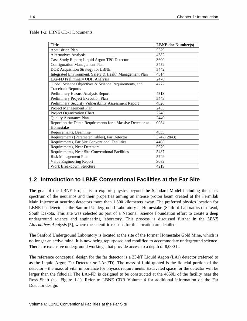
Table 1-2: LBNE CD-1 Documents.
Title LBNE doc Number(s) Acquisition Plan 5329 Alternatives Analysis 4382 Case Study Report; Liquid Argon TPC Detector 3600 Configuration Management Plan 5452 DOE Acquisition Strategy for LBNE 5442 Integrated Environment, Safety & Health Management Plan 4514 LAr-FD Preliminary ODH Analysis 2478 Global Science Objectives & Science Requirements, and Traceback Reports
4772
Preliminary Hazard Analysis Report 4513 Preliminary Project Execution Plan 5443 Preliminary Security Vulnerability Assessment Report 4826 Project Management Plan 2453 Project Organization Chart 2248 Quality Assurance Plan 2449 Report on the Depth Requirements for a Massive Detector at Homestake
0034
Requirements, Beamline 4835 Requirements (Parameter Tables), Far Detector 3747 (2843) Requirements, Far Site Conventional Facilities 4408 Requirements, Near Detectors 5579 Requirements, Near Site Conventional Facilities 5437 Risk Management Plan 5749 Value Engineering Report 3082 Work Breakdown Structure 4219
1.2 Introduction to LBNE Conventional Facilities at the Far Site
The goal of the LBNE Project is to explore physics beyond the Standard Model including the mass spectrum of the neutrinos and their properties aiming an intense proton beam created at the Fermilab Main Injector at neutrino detectors more than 1,300 kilometers away. The preferred physics location for LBNE far detector is the Sanford Underground Laboratory at Homestake (Sanford Laboratory) in Lead, South Dakota. This site was selected as part of a National Science Foundation effort to create a deep underground science and engineering laboratory. This process is discussed further in the LBNE Alternatives Analysis [5], where the scientific reasons for this location are detailed.
The Sanford Underground Laboratory is located at the site of the former Homestake Gold Mine, which is no longer an active mine. It is now being repurposed and modified to accommodate underground science. There are extensive underground workings that provide access to a depth of 8,000 ft.
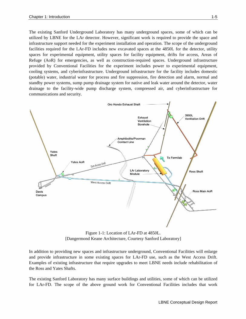
The reference conceptual design for the far detector is a 33-kT Liquid Argon (LAr) detector (referred to as the Liquid Argon Far Detector or LAr-FD). The mass of fluid quoted is the fiducial portion of the detector – the mass of vital importance for physics requirements. Excavated space for the detector will be larger than the fiducial. The LAr-FD is designed to be constructed at the 4850L of the facility near the Ross Shaft (see Figure 1-1). Refer to LBNE CDR Volume 4 for additional information on the Far Detector design.
Chapter 1: Introduction 1-5
LBNE Conceptual Design Report
The existing Sanford Underground Laboratory has many underground spaces, some of which can be utilized by LBNE for the LAr detector. However, significant work is required to provide the space and infrastructure support needed for the experiment installation and operation. The scope of the underground facilities required for the LAr-FD includes new excavated spaces at the 4850L for the detector, utility spaces for experimental equipment, utility spaces for facility equipment, drifts for access, Areas of Refuge (AoR) for emergencies, as well as construction-required spaces. Underground infrastructure provided by Conventional Facilities for the experiment includes power to experimental equipment, cooling systems, and cyberinfrastructure. Underground infrastructure for the facility includes domestic (potable) water, industrial water for process and fire suppression, fire detection and alarm, normal and standby power systems, sump pump drainage system for native and leak water around the detector, water drainage to the facility-wide pump discharge system, compressed air, and cyberinfrastructure for communications and security.
Figure 1-1: Location of LAr-FD at 4850L. [Dangermond Keane Architecture, Courtesy Sanford Laboratory]
In addition to providing new spaces and infrastructure underground, Conventional Facilities will enlarge and provide infrastructure in some existing spaces for LAr-FD use, such as the West Access Drift. Examples of existing infrastructure that require upgrades to meet LBNE needs include rehabilitation of the Ross and Yates Shafts.
The existing Sanford Laboratory has many surface buildings and utilities, some of which can be utilized for LAr-FD. The scope of the above ground work for Conventional Facilities includes that work
1-6 Chapter 1: Introduction
Volume 6: LBNE Conventional Facilities at the Far Site
necessary for LBNE, and not for the general rehabilitation of buildings on the site, which remains the responsibility of the Sanford Laboratory. The Yates and Ross Headframes and Hoist Buildings will receive structural, architectural, and electrical improvements. Electrical substations and distribution will be upgraded to increase power and provide standby capability for life safety. Additional surface scope includes a small control room in an existing building and temporary warehouse space during installation of the experiment. The only new buildings provided for LAr-FD are to support cryogen transfer from the surface to the underground near the existing Oro Hondo Shaft.
1.3 Participants
The Far Detector is planned to be located at the Sanford Laboratory site, which is managed by the South Dakota Science and Technology Authority (SDSTA). The design and construction of LBNE Far Site Conventional Facilities will be executed in conjunction with Sanford Laboratory staff.
The LBNE Project Conventional Facilities is managed by the Work Breakdown Structure (WBS) Level 2 Conventional Facilities Manager. The supporting team includes a WBS Level 3 Manager for Conventional Facilities at Far Site, who works directly with the Sanford Laboratory engineering staff. The Level 3 Far Site Manager is also the LBNE Project liaison with the LAr subproject to ensure the detector requirements are met and is responsible for all LBNE scope at the Far Site. [Management of the Sanford Lab and the organizational relationship between it and the LBNE Project and Fermilab are in the process of being determined; this section will be updated when that is known.]
To date, Sanford Laboratory has utilized a team of in-house facility engineers to oversee multiple engineering design and construction consultants. Design consultants have specific areas of expertise in excavation, rock support, fire/life safety, electrical power distribution, cyberinfrastructure, cooling with chilled water, and heating/ventilation systems. Design consultants for LBNE’s Conceptual Design were: HDR for surface facilities, Arup, USA for underground infrastructure, and Golder Associates for excavation. Interaction between Sanford Laboratory facility engineers, LBNE Far Site design teams, and design consultants was done via weekly telephone conferences, periodic design interface workshops, and electronic mail. The Sanford Laboratory facility engineers coordinated all information between design consultants to assure that design efforts remain on track.
For the LBNE Conceptual Design phase, the McCarthy Kiewit Joint Venture (MK) performed as the construction manager for pre-construction services. MK reviewed the consultant designs for constructability and provided independent estimates of cost and schedule. MK also provided guidance on packaging of design components for contracting as part of the Far Site Conventional Facilities acquisition strategy.
1.4 Codes and Standards
Conventional Facilities to be constructed at the Far Site shall be design and constructed in conformance with the Sanford Underground Laboratory ESH Standards, (EHS-1000-L6-01, document 73205, Version 3, dated September 2, 2010 available publically through Sanford Laboratory’s document management system: https://docs.sanfordlab.org/docushare/dsweb/View/Collection-7391), but particularly the latest edition of the following codes and standards:
Chapter 1: Introduction 1-7
LBNE Conceptual Design Report
Applicable Federal Code of Federal Regulations (CFR), Executive Orders, and DOE Requirements
2009 International Building Code (IBC)
Sanford Underground Laboratory Subterranean Design Criteria, EHS-1000-L3-05
“Fire Protection/Life Safety Assessment for the Conceptual Design of the Far Site of the Long Baseline Neutrino Experiment (LBNE)”, a preliminary assessment dated October 11, 2011, by Aon/Schirmer Engineering
The Occupational Health and Safety Act of 1970 (OSHA)
Mine Safety and Health Administration (MSHA)
NFPA 101, Life Safety Code
NFPA 520, Standard on Subterranean Spaces, 2005 Edition
NFPA 72, National Fire Alarm Code
American Concrete Institute (ACI) 318
American Institute of Steel Construction Manual, 14th Edition
ASHRAE 90.1-2007, Energy Standard for Buildings
ASHRAE 62, Indoor Air Quality
2009 National Electrical Code (NEC)
American Society of Mechanical Engineers (ASME)
American Society for Testing and Material (ASTM)
American National Standards Institute (ANSI)
National Institute of Standards & Technology (NIST)
Insulated Cable Engineers Association (ICEA)
Institute of Electrical and Electronics Engineers (IEEE)
National Electrical Manufacturers Association (NEMA)
American Society of Plumbing Engineers (ASPE)
American Water Works Association (AWWA)
American Society of Sanitary Engineering (ASSE)
American Gas Association (AGA)
National Sanitation Foundation (NSF)
Federal American's with Disabilities Act (ADA) along with State of South Dakota ADA amendments. These requirements shall only be applied to those facilities which are located at the ground surface and accessible to the public.
2-8 Chapter 2: Existing Site Conditions
Volume 6: LBNE Conventional Facilities at the Far Site
2 Existing Site Conditions
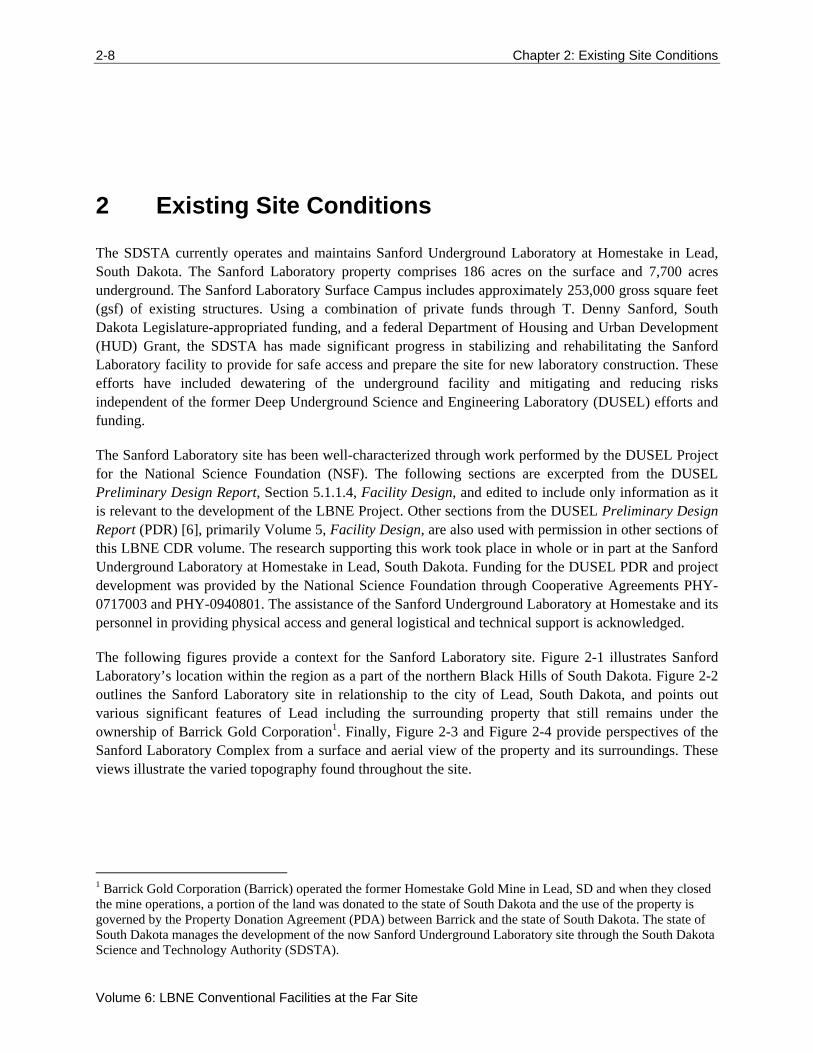
The SDSTA currently operates and maintains Sanford Underground Laboratory at Homestake in Lead, South Dakota. The Sanford Laboratory property comprises 186 acres on the surface and 7,700 acres underground. The Sanford Laboratory Surface Campus includes approximately 253,000 gross square feet (gsf) of existing structures. Using a combination of private funds through T. Denny Sanford, South Dakota Legislature-appropriated funding, and a federal Department of Housing and Urban Development (HUD) Grant, the SDSTA has made significant progress in stabilizing and rehabilitating the Sanford Laboratory facility to provide for safe access and prepare the site for new laboratory construction. These efforts have included dewatering of the underground facility and mitigating and reducing risks independent of the former Deep Underground Science and Engineering Laboratory (DUSEL) efforts and funding.
The Sanford Laboratory site has been well-characterized through work performed by the DUSEL Project for the National Science Foundation (NSF). The following sections are excerpted from the DUSEL Preliminary Design Report, Section 5.1.1.4, Facility Design, and edited to include only information as it is relevant to the development of the LBNE Project. Other sections from the DUSEL Preliminary Design Report (PDR) [6], primarily Volume 5, Facility Design, are also used with permission in other sections of this LBNE CDR volume. The research supporting this work took place in whole or in part at the Sanford Underground Laboratory at Homestake in Lead, South Dakota. Funding for the DUSEL PDR and project development was provided by the National Science Foundation through Cooperative Agreements PHY-0717003 and PHY-0940801. The assistance of the Sanford Underground Laboratory at Homestake and its personnel in providing physical access and general logistical and technical support is acknowledged.
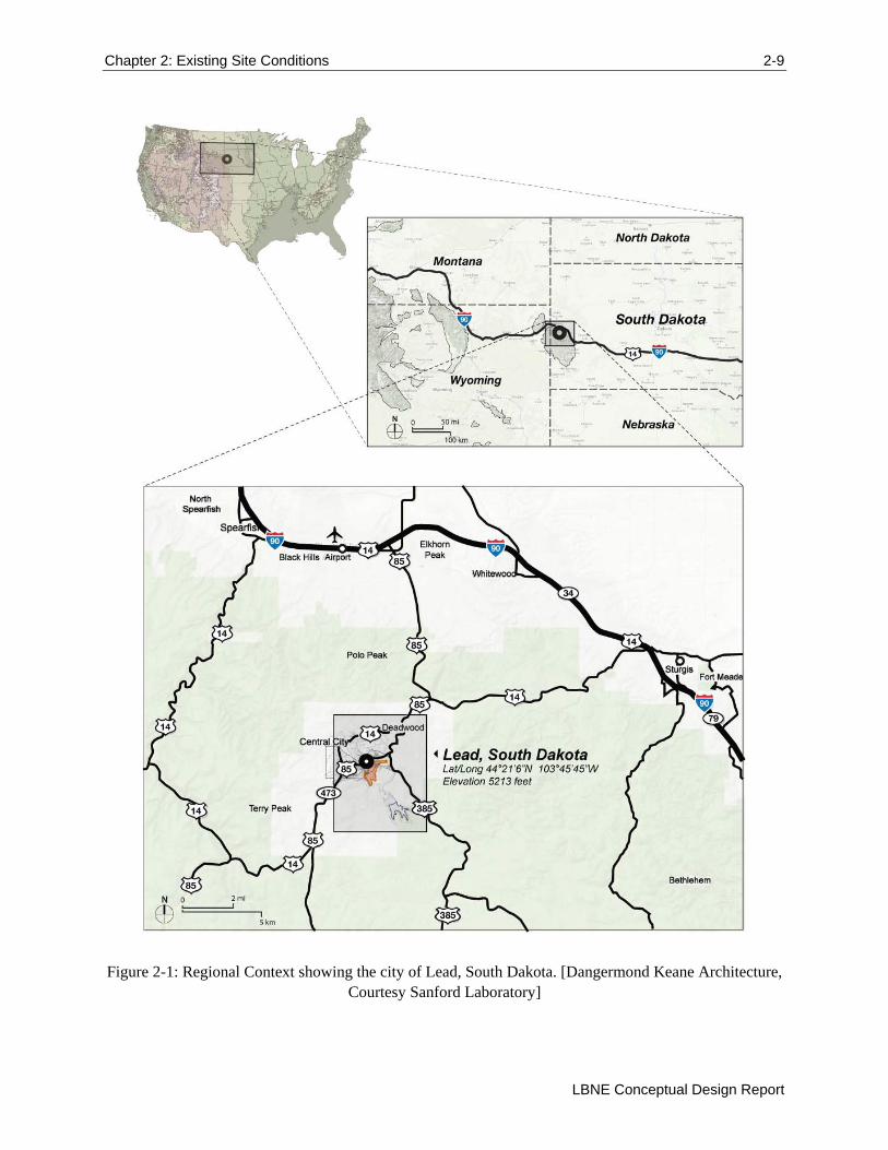
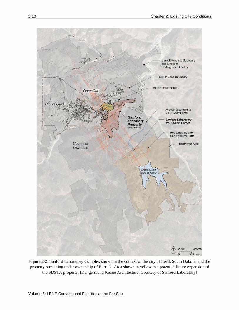
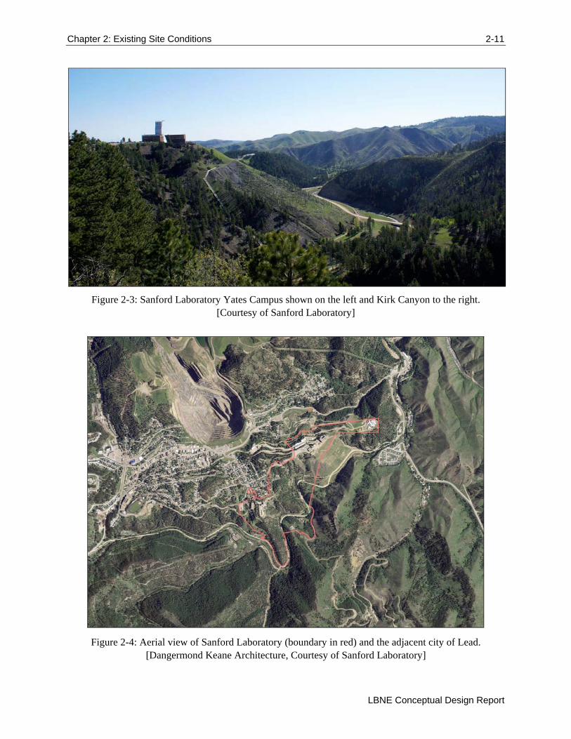
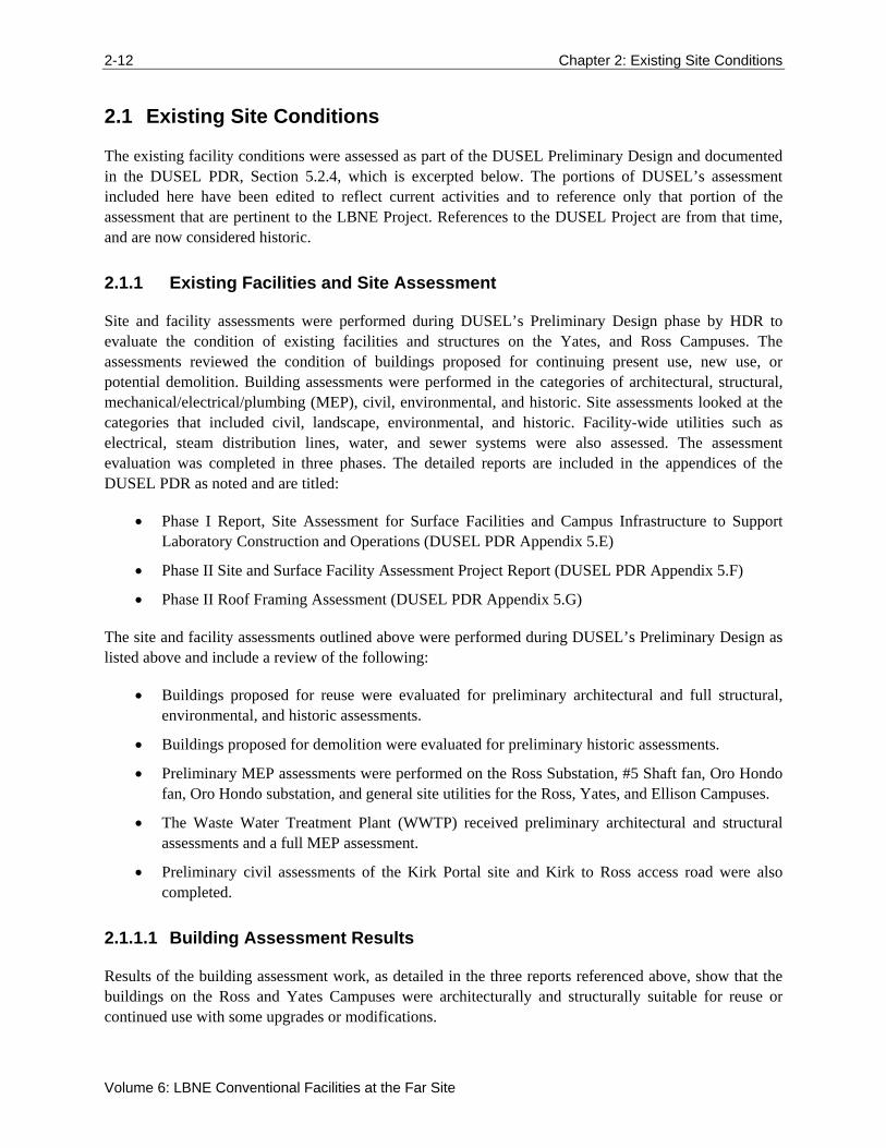
The following figures provide a context for the Sanford Laboratory site. Figure 2-1 illustrates Sanford Laboratory’s location within the region as a part of the northern Black Hills of South Dakota. Figure 2-2 outlines the Sanford Laboratory site in relationship to the city of Lead, South Dakota, and points out various significant features of Lead including the surrounding property that still remains under the ownership of Barrick Gold Corporation1. Finally, Figure 2-3 and Figure 2-4 provide perspectives of the Sanford Laboratory Complex from a surface and aerial view of the property and its surroundings. These views illustrate the varied topography found throughout the site.
1 Barrick Gold Corporation (Barrick) operated the former Homestake Gold Mine in Lead, SD and when they closed the mine operations, a portion of the land was donated to the state of South Dakota and the use of the property is governed by the Property Donation Agreement (PDA) between Barrick and the state of South Dakota. The state of South Dakota manages the development of the now Sanford Underground Laboratory site through the South Dakota Science and Technology Authority (SDSTA).
Chapter 2: Existing Site Conditions 2-9
LBNE Conceptual Design Report
Figure 2-1: Regional Context showing the city of Lead, South Dakota. [Dangermond Keane Architecture, Courtesy Sanford Laboratory]
2-10 Chapter 2: Existing Site Conditions
Volume 6: LBNE Conventional Facilities at the Far Site
Figure 2-2: Sanford Laboratory Complex shown in the context of the city of Lead, South Dakota, and the property remaining under ownership of Barrick. Area shown in yellow is a potential future expansion of
the SDSTA property. [Dangermond Keane Architecture, Courtesy of Sanford Laboratory]
Chapter 2: Existing Site Conditions 2-11
LBNE Conceptual Design Report
Figure 2-3: Sanford Laboratory Yates Campus shown on the left and Kirk Canyon to the right. [Courtesy of Sanford Laboratory]
Figure 2-4: Aerial view of Sanford Laboratory (boundary in red) and the adjacent city of Lead. [Dangermond Keane Architecture, Courtesy of Sanford Laboratory]
2-12 Chapter 2: Existing Site Conditions
Volume 6: LBNE Conventional Facilities at the Far Site
2.1 Existing Site Conditions
The existing facility conditions were assessed as part of the DUSEL Preliminary Design and documented in the DUSEL PDR, Section 5.2.4, which is excerpted below. The portions of DUSEL’s assessment included here have been edited to reflect current activities and to reference only that portion of the assessment that are pertinent to the LBNE Project. References to the DUSEL Project are from that time, and are now considered historic.
2.1.1 Existing Facilities and Site Assessment
Site and facility assessments were performed during DUSEL’s Preliminary Design phase by HDR to evaluate the condition of existing facilities and structures on the Yates, and Ross Campuses. The assessments reviewed the condition of buildings proposed for continuing present use, new use, or potential demolition. Building assessments were performed in the categories of architectural, structural, mechanical/electrical/plumbing (MEP), civil, environmental, and historic. Site assessments looked at the categories that included civil, landscape, environmental, and historic. Facility-wide utilities such as electrical, steam distribution lines, water, and sewer systems were also assessed. The assessment evaluation was completed in three phases. The detailed reports are included in the appendices of the DUSEL PDR as noted and are titled:
Phase I Report, Site Assessment for Surface Facilities and Campus Infrastructure to Support Laboratory Construction and Operations (DUSEL PDR Appendix 5.E)
Phase II Site and Surface Facility Assessment Project Report (DUSEL PDR Appendix 5.F)
Phase II Roof Framing Assessment (DUSEL PDR Appendix 5.G)
The site and facility assessments outlined above were performed during DUSEL’s Preliminary Design as listed above and include a review of the following:
Buildings proposed for reuse were evaluated for preliminary architectural and full structural, environmental, and historic assessments.
Buildings proposed for demolition were evaluated for preliminary historic assessments.
Preliminary MEP assessments were performed on the Ross Substation, #5 Shaft fan, Oro Hondo fan, Oro Hondo substation, and general site utilities for the Ross, Yates, and Ellison Campuses.
The Waste Water Treatment Plant (WWTP) received preliminary architectural and structural assessments and a full MEP assessment.
Preliminary civil assessments of the Kirk Portal site and Kirk to Ross access road were also completed.
2.1.1.1 Building Assessment Results
Results of the building assessment work, as detailed in the three reports referenced above, show that the buildings on the Ross and Yates Campuses were architecturally and structurally suitable for reuse or continued use with some upgrades or modifications.
Chapter 2: Existing Site Conditions 2-13
LBNE Conceptual Design Report
2.1.1.2 Site Civil Assessment
Results of the civil assessment found in the Phase I Report, Site Assessment for Surface Facilities and Campus Infrastructure to Support Laboratory Construction and Operations (DUSEL PDR Appendix 5.E) and Phase II Site and Facility Assessment, Project Report (DUSEL PDR Appendix 5.F) showed the following results:
Water and sewer utilities on both the Ross and Yates Campuses need replacement.
Roadway and parking lot surfaces need replacement and regrading. Drainage ways and steep slopes need maintenance.
Retaining walls and transportation structures are in useable condition, with some maintenance, except for two failing retaining walls.
Retaining walls and transportation structures need maintenance in the form of drainage improvements and minor repairs to section loss due to rust and erosion.
Existing fencing and guardrails are a very inconsistent pattern of chain link, wood, and steel; much of the fencing is deteriorating or collapsed.
Abandoned equipment/scrap-metal piles around the sites represent traffic and health hazards.
Pedestrian and traffic separation is poorly defined.
Existing traffic signs are faded and do not meet Manual of Uniform Traffic Control Devices (MUTCD) standards.
The Civil Site Assessment recommendations can be found in DUSEL PDR Appendix 5.E (Section 4, Page 4(1) of the Phase I Report, Site Assessment for Surface Facilities and Campus Infrastructure to Support Laboratory Construction and Operations); and DUSEL PDR Appendix 5.F (Section 2, Page (2.1) – 39 of the Phase II Site and Facility Assessment Project Report). All items that would cause immediate concern for the health and safety of on-site personnel have been addressed by the SDSTA by removing, repairing, or isolating the concerns.
2.1.1.3 Landscape Assessment
The landscape assessment, found in DUSEL PDR Appendix 5.E (Phase I Report, Site Assessment for Surface Facilities and Campus Infrastructure to Support Laboratory Construction and Operations); and DUSEL PDR Appendix 5.F (Phase II Site and Surface Facility Assessment Project Report) noted many of the same items as the site civil assessment: drainage issues, erosion concerns, abandoned equipment, and scrap metal. Soil conditions were noted as well as rock escarpments and soil stability concerns.
2.1.1.4 Site MEP Assessment
The site assessments, detailed in DUSEL PDR Appendix 5.E (Phase I Report, Site Assessment for Surface Facilities and Campus Infrastructure to Support Laboratory Construction and Operations); and DUSEL PDR Appendix 5.F (Phase II Site and Surface Facility Assessment Project Report) found the electrical distribution condition to range from fair to excellent, depending on the age of the equipment. The Ross Campus recommendations generally consisted of upgrades to increase reliability. The Yates
2-14 Chapter 2: Existing Site Conditions
Volume 6: LBNE Conventional Facilities at the Far Site
Campus recommendations call for a new substation to replace the old abandoned East Substation if significant loads are added to this campus.
The assessments also evaluated the natural gas and steam distribution systems. Natural gas is provided to the site at three locations and appears to have the capacity required to meet surface needs as they are currently understood. However, the natural gas supply is an interruptible supply (non-firm) and thus cannot be guaranteed. Either an upgrade to Montana-Dakota Utilities (MDU, local natural gas supplier) supply lines (outside the scope of this Project) or an alternate fuel/heating source will be needed to meet the surface needs. The steam boiler systems have been dismantled and should not be reused. The existing components represent placeholders for routing for new distribution if steam is re-employed.
The site telecommunications service currently is provided by Knology Inc., Rapid City, South Dakota, and a fiber-optic data connection is from the South Dakota Research, Education and Economic Development (REED) Network (see DUSEL PDR Chapter 5.5, Cyberinfrastructure Systems Design, for details on these service providers). Both services are quite new and have historically been very reliable. The site distribution system is a mix of copper and fiber, copper being quite old and fiber very new. The Ross and Yates Campus’ recommendations are to increase reliability as the campuses are developed.
2.1.1.5 Environmental Assessment
The environmental assessment, found in DUSEL PDR Appendix 5.F (Phase II Site and Surface Facility Assessment Project Report) looked for contamination from lead-based paint (LBP); polychlorinated biphenyls (PCBs) contained in electrical equipment, lubrication oils, and hydraulics; asbestos-containing building materials (ACBMs); heavy metals; the historic presence of petroleum hydrocarbons and chlorinated solvents; molds; historic uncontrolled discharges of domestic sewage; industrial wastewater; and storm-water runoff. Environmental results showed some LBPs in various locations across both the Ross and Yates Campuses. No PCB concentrations above Environmental Protection Agency (EPA) regulatory standards were encountered, and no heavy metals above EPA regulatory standards were found.
2.1.1.6 Historic Assessment
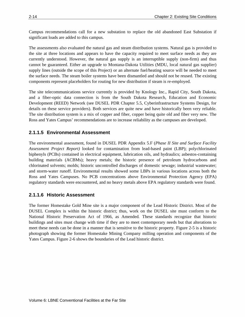
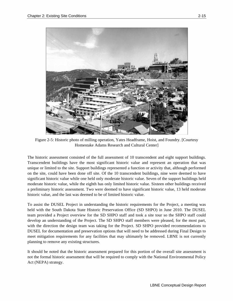
The former Homestake Gold Mine site is a major component of the Lead Historic District. Most of the DUSEL Complex is within the historic district; thus, work on the DUSEL site must conform to the National Historic Preservation Act of 1966, as Amended. These standards recognize that historic buildings and sites must change with time if they are to meet contemporary needs but that alterations to meet these needs can be done in a manner that is sensitive to the historic property. Figure 2-5 is a historic photograph showing the former Homestake Mining Company milling operation and components of the Yates Campus. Figure 2-6 shows the boundaries of the Lead historic district.
Chapter 2: Existing Site Conditions 2-15
LBNE Conceptual Design Report
Figure 2-5: Historic photo of milling operation, Yates Headframe, Hoist, and Foundry. [Courtesy Homestake Adams Research and Cultural Center]
The historic assessment consisted of the full assessment of 10 transcendent and eight support buildings. Transcendent buildings have the most significant historic value and represent an operation that was unique or limited to the site. Support buildings represented a function or activity that, although performed on the site, could have been done off site. Of the 10 transcendent buildings, nine were deemed to have significant historic value while one held only moderate historic value. Seven of the support buildings held moderate historic value, while the eighth has only limited historic value. Sixteen other buildings received a preliminary historic assessment. Two were deemed to have significant historic value, 13 held moderate historic value, and the last was deemed to be of limited historic value.
To assist the DUSEL Project in understanding the historic requirements for the Project, a meeting was held with the South Dakota State Historic Preservation Office (SD SHPO) in June 2010. The DUSEL team provided a Project overview for the SD SHPO staff and took a site tour so the SHPO staff could develop an understanding of the Project. The SD SHPO staff members were pleased, for the most part, with the direction the design team was taking for the Project. SD SHPO provided recommendations to DUSEL for documentation and preservation options that will need to be addressed during Final Design to meet mitigation requirements for any facilities that may ultimately be removed. LBNE is not currently planning to remove any existing structures.
It should be noted that the historic assessment prepared for this portion of the overall site assessment is not the formal historic assessment that will be required to comply with the National Environmental Policy Act (NEPA) strategy.
2-16 Chapter 2: Existing Site Conditions
Volume 6: LBNE Conventional Facilities at the Far Site
See section 3.2.1 of this volume for additional information about the LBNE NEPA strategy.2
The entire historic assessment process and results can be viewed in DUSEL PDR Appendix 5.E (Phase I Report, Site Assessment for Surface Facilities and Campus Infrastructure to Support Laboratory Construction and Operations), and DUSEL PDR Appendix 5.F (Phase II Site and Surface Facility Assessment Project Report).
Figure 2-6: Map of Lead Historic District. [Dangermond Keane Architecture, Courtesy of Sanford Laboratory]
2.2 Geology and Existing Excavations
LBNE Far Site facilities are planned to be constructed at Sanford Laboratory which is being developed within the footprint of the former Homestake Gold Mine, located in Lead, South Dakota. The accessible underground mine workings are extensive. Over the life of the former gold mine some 360 miles of drifts (tunnels) were mined and shafts and winzes sunk to gain access to depths in excess of 8,000 feet. A number of underground workings are being refurbished by Sanford Laboratory and new experiments are being developed at the 4850L, the same level as proposed for LBNE LAr-FD facilities. Geotechnical
2 For clarity, this discussion of NEPA activities was developed for this Conceptual Design Report and inserted into this section of text which is largely copied from the DUSEL Preliminary Design Report. Discussions on NEPA were not included in the text of the DUSEL Preliminary Design Report.
Chapter 2: Existing Site Conditions 2-17
LBNE Conceptual Design Report
investigations and initial geotechnical analyses have been completed for the DUSEL Preliminary Design and are described in detail in the DUSEL PDR. Below are summaries of some of the work completed to date that is applicable to LBNE as excerpted from the DUSEL Preliminary Design Report, Chapter 5.3, and edited to include only information as it is relevant to the development of the LBNE Project. Much of the work completed for the alternate detector technology considered by LBNE (water Cherenkov detector [WCD]) is also applicable to LAr-FD at the 4850L.
2.2.1 Geologic Setting
The Sanford Laboratory is sited within a metamorphic complex containing the Poorman, Homestake, Ellison and Northwestern Formations (oldest to youngest), which are sedimentary and volcanic in origin. An amphibolite unit (Yates Member) is present within the lower known portions of the Poorman Formation. While the Yates Member is the preferred host rock for the LBNE excavations at 4850L, the LAr-FD cavity has been located in the Poorman formation to isolate it from the remainder of the level. The layout adopted on the 4850L attempts to optimize the needs for ventilation isolation, access control, and orientation relative to the beam line.
2.2.2 Rock Mass Characterization
One of the goals of the geotechnical investigations performed to date by the DUSEL Project was to provide information for the excavation and stabilization of an alternative large cavity for a Water Cherenkov Detector (WCD) supporting the Long Baseline Neutrino Experiment (LBNE). Characterization of the rock mass (see DUSEL PDR Sections 5.3.2 and 5.3.3) was accomplished through a program of mapping existing drifts and rooms in the vicinity of planned excavations, drilling and geotechnical logging of rock core samples, and laboratory measurements of the properties of those samples. Much of the geotechnical work performed for WCD is applicable to LAr-FD at the 4850L.
As part of the Preliminary Design process, the DUSEL Project engaged two advisory boards to provide expert review of the geotechnical investigation and excavation design efforts. The Geotechnical Advisory Committee (GAC) was an internal committee that focused primarily on geotechnical investigation and analysis. The Large Cavity Advisory Board (LCAB) was an internal high-level board that focused on geotechnical investigations and excavation design of the WCD cavity in support of the LBNE Project, much of which is applicable to LAr-FD at the 4850L. The Geotechnical Engineering Services (GES) contract, which was used to execute geotechnical investigations, was reviewed by the GAC and the LCAB and included the following scope of work:
The mapping program included drift mapping at the 300L and 4850L and 4,400 ft (1,340 m) of existing drifts mapped in detail and 2,600 ft (793 m) of newly excavated drifts and large openings mapped in detail (Davis Campus, Transition Area, and associated connecting drifts).
The drilling program included the completion of nine new holes totaling 5,399 ft (1,646 m) of HQ (4-inch) diamond core drilling, which incorporated continuous logging, continuous core orientation, detailed geotechnical and geological logging, full depth continuous televiewer imaging, and initial groundwater monitoring.
2-18 Chapter 2: Existing Site Conditions
Volume 6: LBNE Conventional Facilities at the Far Site
The in situ stress measurement program included stress measurements in three locations; two sites in amphibolite and one site in rhyolite for the total of eight measurements (six in amphibolite and two in rhyolite).
The laboratory testing program included uniaxial compressive strength tests (80 samples that incorporated elastic constants and failure criteria), indirect tensile strength tests (40 samples), triaxial compressive strength tests (63 samples), and direct shear strength of discontinuities (36 samples).
Geotechnical investigations were initiated by DUSEL in January 2009 and executed by RESPEC Inc., with Golder Associates and Lachel Felice & Associates (LFA) as their main subcontractors. The initial scope was modified to include the addition of a 100kT water Cherenkov detector (WCD). The scope was further modified, resulting in the requirement for the potential to include up to two 100kT WCDs into the DUSEL Preliminary Design effort. In mid-2010, the DUSEL Preliminary Design scope was narrowed to one WCD. Subsequently, the project has considered locating a LAr detector on the same level.
In mid-2009, an initial geotechnical program was executed by DUSEL, first on the 300L, then on the 4850L of the Homestake site. This program included site mapping, reconnaissance level geotechnical drilling and core logging, in situ stress measurements, optical and acoustic televiewer logging, numerical modeling, laboratory testing, initial surveying, and generation of a three dimensional (3D) Geological and Geotechnical Model. Additional tasks added in 2010 included characterization of ground vibrations from blasting associated with the Davis Campus excavation activities, and groundwater monitoring. A Geotechnical Engineering Summary Report (DUSEL PDR Appendix 5.H) was completed in March 2010, which recommended additional drilling and mapping to address data gaps and reduce uncertainty in the characterization of the rock mass that would be important for future phases of design. All of the geologic, geotechnical, and hydrogeologic information collected has been used to advance the Conceptual Design of the LAr-FD at the 4850L.
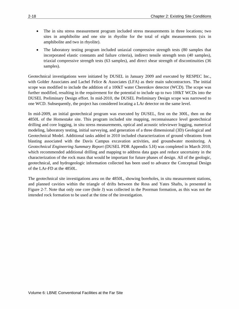
The geotechnical site investigations area on the 4850L, showing boreholes, in situ measurement stations, and planned cavities within the triangle of drifts between the Ross and Yates Shafts, is presented in Figure 2-7. Note that only one core (hole J) was collected in the Poorman formation, as this was not the intended rock formation to be used at the time of the investigation.
Chapter 2: Existing Site Conditions 2-19
LBNE Conceptual Design Report
Figure 2-7: General geologic map at the 4850L and location of drill holes. [Golder Associates, Courtesy Sanford Laboratory]
2-20 Chapter 2: Existing Site Conditions
Volume 6: LBNE Conventional Facilities at the Far Site
Since their formation, the host rock units have been subject to periods of significant structural deformation. Deformations during the Precambrian era lead to the development of complex fold patterns, and local shear zones. Brittle deformations that took place during the Tertiary era resulted in the development of joint sets, veining, faulting and the intrusion of dikes [7]. Tertiary rhyolite dikes cross-cut the Precambrian rock units across the former mine site, from surface (open cut) to the deepest development levels (>8,000ft). In the areas of the 4850L observed and investigated to date, these dikes are commonplace. Rhyolite is estimated to constitute some 40% of the country rock volume in the area of the proposed campus. Faulting and veining have also been observed within the host rock mass (Lachel Felice & Associates, Geotechnical Engineering Services Final Report for 4850L Mapping [8], and Golder Associates, LBNE Far Site Detector Excavation Conceptual Design: 4850 Level Liquid Argon (LAr) Reference Design Final Report [9]).
The in situ stress levels at various levels of the Sanford Laboratory underground facility have been measured on a number of occasions. The major principle stress, at depth, is sub-vertical. Recent measurements on the 4850L report a range of vertical stress values, from 22 to 61 MPa (3.2 to 8.8 ksi) (average 44Mpa / 6.4ksi). Measured intermediate: major and minor: major stress ratios were reported to be 0.6 to 0.8 and 0.5 to 0.7 respectively. For further details, see Golder’s Geotechnical Engineering Services, In Situ Stress Measurement Deep Underground Science and Engineering Laboratory [10].
The intact hard metamorphic rocks are generally of low primary hydrologic conductivity. During historic mine operations most water inflows were observed to be local and typically attributed to secondary permeability [11]. A recent evaluation by Golder [9] estimates the typical inflow rate of about 1 to 2 gallons per minute per mile of underground workings. Some additional flow may be anticipated in the upper workings where fractures may be generally more weathered, open and directly connected to the surface and/or the Open Cut.
2.2.3 Geologic Conclusions
The recovery of rock cores, plus geologic mapping, was performed to determine if discontinuities in the rock mass exist that would cause difficulties in the construction and maintenance of planned excavations. In general, the proposed locations of the excavations do not appear to be complicated by geologic structures that cause undue difficulties for construction. This information, along with measurement of in situ stresses, allowed initial numerical modeling [9] of the stresses associated with the anticipated excavations. 2D and 3D numerical modeling was then used to design ground support systems that will ensure that the LAr-FD cavern, in particular, remains stable. The excavation design, which is influenced by anticipated methods of excavation and sequence of excavation, is described in Golder Associates Conceptual Design [9], followed by the means by which the excavations will be monitored to ensure their long-term stability.
The overall analysis of the work indicates that the rock in the proposed location of the LAr-FD cavern is of good quality for the purposes of the LBNE Project, that preliminary numerical modeling shows that a large cavern of the size envisioned can be constructed, and that a workable excavation design has been developed.
Chapter 3: The Facility Layout 3-21
LBNE Conceptual Design Report
3 The Facility Layout
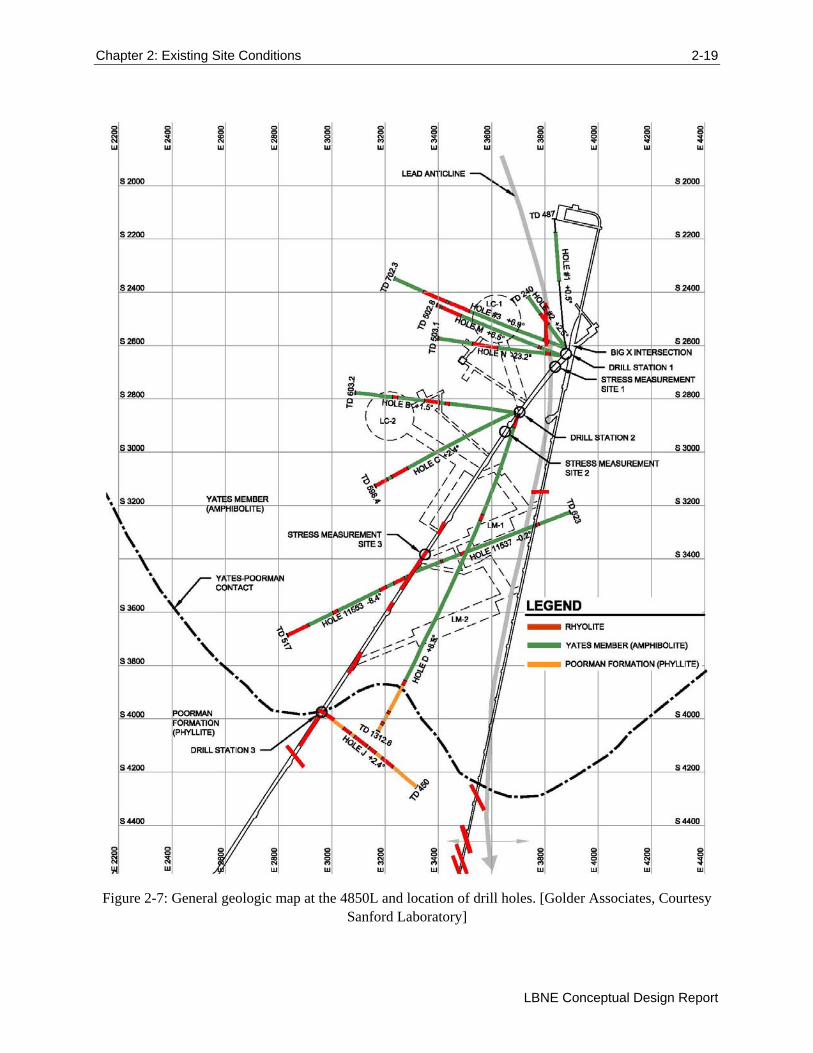
The Sanford Laboratory property of 186 acres consists of steep terrain and man-made cuts dating from its mining history. There are approximately 50 buildings and associated site infrastructure in various states of repair. A select few of these buildings and the main utilities are needed by the LAr-FD experiment and will be upgraded and rehabilitated as necessary. HDR prepared a conceptual design for surface facility improvements for LAr-FD that can be found in LAr 4850L Conceptual Design Report [12]. This section summarizes the work done by HDR and utilizes information from that report.
A layout of the overall Sanford Laboratory architectural site plan for the LBNE Project is found in Figure 3-1.
Figure 3-1: Architectural Site Plan. [HDR]
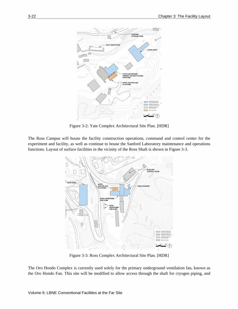
The Yates Campus contains the main Sanford Laboratory Administration building. Layout of surface facilities in the vicinity of the Yates Shaft is shown in Figure 3-2.
3-22 Chapter 3: The Facility Layout
Volume 6: LBNE Conventional Facilities at the Far Site
Figure 3-2: Yate Complex Architectural Site Plan. [HDR]
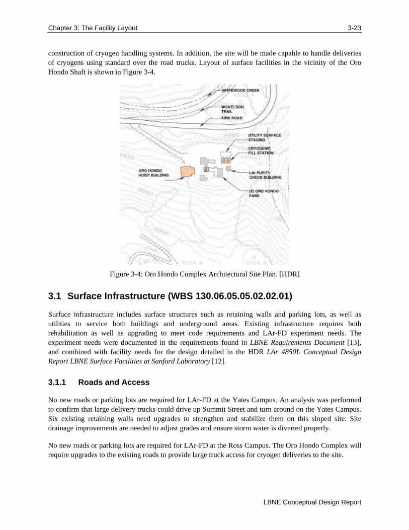
The Ross Campus will house the facility construction operations, command and control center for the experiment and facility, as well as continue to house the Sanford Laboratory maintenance and operations functions. Layout of surface facilities in the vicinity of the Ross Shaft is shown in Figure 3-3.
Figure 3-3: Ross Complex Architectural Site Plan. [HDR]
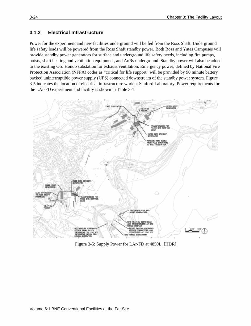
The Oro Hondo Complex is currently used solely for the primary underground ventilation fan, known as the Oro Hondo Fan. This site will be modified to allow access through the shaft for cryogen piping, and
Chapter 3: The Facility Layout 3-23
LBNE Conceptual Design Report
construction of cryogen handling systems. In addition, the site will be made capable to handle deliveries of cryogens using standard over the road trucks. Layout of surface facilities in the vicinity of the Oro Hondo Shaft is shown in Figure 3-4.
Figure 3-4: Oro Hondo Complex Architectural Site Plan. [HDR]
3.1 Surface Infrastructure (WBS 130.06.05.05.02.02.01)
Surface infrastructure includes surface structures such as retaining walls and parking lots, as well as utilities to service both buildings and underground areas. Existing infrastructure requires both rehabilitation as well as upgrading to meet code requirements and LAr-FD experiment needs. The experiment needs were documented in the requirements found in LBNE Requirements Document [13], and combined with facility needs for the design detailed in the HDR LAr 4850L Conceptual Design Report LBNE Surface Facilities at Sanford Laboratory [12].
3.1.1 Roads and Access
No new roads or parking lots are required for LAr-FD at the Yates Campus. An analysis was performed to confirm that large delivery trucks could drive up Summit Street and turn around on the Yates Campus. Six existing retaining walls need upgrades to strengthen and stabilize them on this sloped site. Site drainage improvements are needed to adjust grades and ensure storm water is diverted properly.
No new roads or parking lots are required for LAr-FD at the Ross Campus. The Oro Hondo Complex will require upgrades to the existing roads to provide large truck access for cryogen deliveries to the site.
3-24 Chapter 3: The Facility Layout
Volume 6: LBNE Conventional Facilities at the Far Site
3.1.2 Electrical Infrastructure
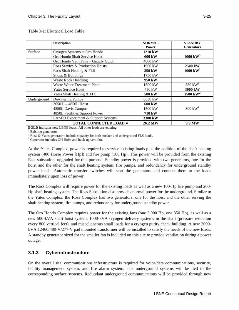
Power for the experiment and new facilities underground will be fed from the Ross Shaft. Underground life safety loads will be powered from the Ross Shaft standby power. Both Ross and Yates Campuses will provide standby power generators for surface and underground life safety needs, including fire pumps, hoists, shaft heating and ventilation equipment, and AoRs underground. Standby power will also be added to the existing Oro Hondo substation for exhaust ventilation. Emergency power, defined by National Fire Protection Association (NFPA) codes as “critical for life support” will be provided by 90 minute battery backed uninterruptible power supply (UPS) connected downstream of the standby power system. Figure 3-5 indicates the location of electrical infrastructure work at Sanford Laboratory. Power requirements for the LAr-FD experiment and facility is shown in Table 3-1.
Figure 3-5: Supply Power for LAr-FD at 4850L. [HDR]
Chapter 3: The Facility Layout 3-25
LBNE Conceptual Design Report
Table 3-1: Electrical Load Table.
Description NORMAL Power
STANDBY Generators
Surface Cryogen Systems at Oro Hondo 1210 kW Oro Hondo Shaft Service Hoist 600 kW 1000 kW3 Oro Hondo Vent Fans + Grizzly Gulch 4000 kW Ross Service & Production Hoists 1900 kW 2500 kW Ross Shaft Heating & FLS 350 kW 1000 kW2 Shops & Buildings 1750 kW Waste Rock Handling 950 kW Waste Water Treatment Plant 1500 kW 580 kW1 Yates Service Hoist 750 kW 3000 kW Yates Shaft Heating & FLS 580 kW 1500 kW2 Underground Dewatering Pumps 6530 kW 3650 L – 4850L Hoist 600 kW 4850L Davis Campus 1500 kW 300 kW1 4850L Facilities Support Power 710 kW LAr-FD Experiment & Support Systems 3300 kW
TOTAL CONNECTED LOAD = 26.2 MW 9.9 MW BOLD indicates new LBNE loads. All other loads are existing. 1 Existing generators. 2 Ross & Yates generators include capacity for both surface and underground FLS loads. 3 Generator includes OH Hoist and back-up vent fan.
At the Yates Complex, power is required to service existing loads plus the addition of the shaft heating system (400 Horse Power [Hp]) and fire pump (100 Hp). This power will be provided from the existing East substation, upgraded for this purpose. Standby power is provided with two generators, one for the hoist and the other for the shaft heating system, fire pumps, and redundancy for underground standby power loads. Automatic transfer switches will start the generators and connect them to the loads immediately upon loss of power.
The Ross Complex will require power for the existing loads as well as a new 100-Hp fire pump and 200-Hp shaft heating system. The Ross Substation also provides normal power for the underground. Similar to the Yates Complex, the Ross Complex has two generators, one for the hoist and the other serving the shaft heating system, fire pumps, and redundancy for underground standby power.
The Oro Hondo Complex requires power for the existing fans (one 3,000 Hp, one 350 Hp), as well as a new 500-kVA shaft hoist system, 1000-kVA cryogen delivery systems in the shaft (pressure reduction every 800 vertical feet), and miscellaneous small loads for a cryogen purity check building. A new 2000-kVA 12460/480-V/277-V pad mounted transformer will be installed to satisfy the needs of the new loads. A standby generator sized for the smaller fan is included on this site to provide ventilation during a power outage.
3.1.3 Cyberinfrastructure
On the overall site, communications infrastructure is required for voice/data communications, security, facility management system, and fire alarm system. The underground systems will be tied to the corresponding surface systems. Redundant underground communications will be provided through new
3-26 Chapter 3: The Facility Layout
Volume 6: LBNE Conventional Facilities at the Far Site
backbone cables in both the Ross and Yates Shafts with connection at the 4850L and interconnected at the 4850L to provide redundancy. Additional communications are provided through the Oro Hondo shaft to the 3650L and the new borehole from the 3650L to the 4850L for the cryogen delivery system. The campus fiber and copper backbone network will be upgraded and extended to the existing Ross Hoist Building telecommunications closet and a new closet in the Yates Hoist Building. The Yates Campus will be the main IT source, with the Ross as backup. Surface network connection will be done through existing tunnels as much as practical. New routes will be created in ductbanks. Surface connections will include connection to the Ross Dry control room and Yates Administration Building.
3.1.4 Mechanical and HVAC
Ventilation for the underground systems is provided by equipment at the Ross and Yates Campuses. New equipment is required to meet life safety codes. Heating of the supplied air is required to prevent ice formation in the Ross and Yates Shafts during cold weather. Air handling units (AHUs) are equipped with filtration, fans and indirect natural gas‐fired furnace sections. All major system components will be provided with a stand‐by unit utilizing an N+1 design approach. If one of the AHUs were to fail, the stand‐by component will provide 100% redundancy.
The shaft ventilation system for the Yates Shaft is proposed to be located outside of the existing Yates Headframe on a new mezzanine above the west roll up access door. The normal ventilation load for the Yates Shaft will be 200,000 cubic feet per minute (CFM). This volume corresponds with the minimum flow capacity of the existing Oro Hondo fan as well as the requirements for heat removal from the LAr-FD experiment. This would be met by three AHUs, each sized at 100,000 CFM, permitting two units to meet the required capacity and one unit to act as stand‐by should a unit fail or be shut down for maintenance. Should interim construction conditions require higher ventilation rates, the redundant AHU could be put into service and/or supplemental, heated, make‐up air will be provided by the construction contractors. In order to provide some level of temperature control within the shaft the supply air temperature from the AHUs will be maintained at a minimum level of 45°F. No cooling will be provided.
3.1.5 Plumbing Systems
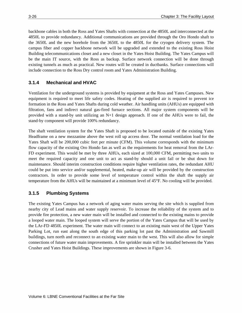
The existing Yates Campus has a network of aging water mains serving the site which is supplied from nearby city of Lead mains and water supply reservoir. To increase the reliability of the system and to provide fire protection, a new water main will be installed and connected to the existing mains to provide a looped water main. The looped system will serve the portion of the Yates Campus that will be used by the LAr-FD 4850L experiment. The water main will connect to an existing main west of the Upper Yates Parking Lot, run east along the south edge of this parking lot past the Administration and Sawmill buildings, turn north and reconnect to an existing water main to the west. This will also allow for simple connections of future water main improvements. A fire sprinkler main will be installed between the Yates Crusher and Yates Hoist Buildings. These improvements are shown in Figure 3-6.
Chapter 3: The Facility Layout 3-27
LBNE Conceptual Design Report
Figure 3-6: Yates Complex civil site plan including water distribution system. [HDR]
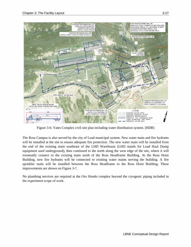
The Ross Campus is also served by the city of Lead municipal system. New water main and fire hydrants will be installed at the site to ensure adequate fire protection. The new water main will be installed from the end of the existing main southeast of the LHD Warehouse (LHD stands for Load Haul Dump equipment used underground), then continued to the north along the west edge of the site, where it will eventually connect to the existing main north of the Ross Headframe Building. At the Ross Hoist Building, new fire hydrants will be connected to existing water mains serving the building. A fire sprinkler main will be installed between the Ross Headframe to the Ross Hoist Building. These improvements are shown on Figure 3-7.
No plumbing services are required at the Oro Hondo complex beyond the cryogenic piping included in the experiment scope of work.
3-28 Chapter 3: The Facility Layout
Volume 6: LBNE Conventional Facilities at the Far Site
Figure 3-7: Ross Complex civil site plan. [HDR]
3.1.5.1 Potable and Industrial Water Systems
The city of Lead provides two type of water to the site. Industrial water is provided from a mountain stream source several miles away directly to the site. This system was installed by the former Homestake Mining Company specifically for underground mining, and therefore it provides a reliable direct source of water. Potable water treats a side stream of the industrial water supply by filtering and adding fluorine and/or chlorine to the water.
The Yates Campus water system will supply an 8‐inch potable water line into the Yates Headframe Building and up to the shaft collar in order to support the underground water needs. Industrial cold water will be provided to serve all detector support systems that require an industrial water supply. The industrial cold water distribution system will be connected to the potable water system for redundant fire protection, but isolated using a reduced pressure backflow preventer (RPBP). The potable and industrial cold water distribution piping will be galvanized steel pipe. Piping has been sized for a maximum velocity of 8 fps for the cold water.
The Ross Campus water system will supply an 8‐inch industrial water line into the Ross Headframe Building and up to the shaft collar in order to support the underground water needs.
Chapter 3: The Facility Layout 3-29
LBNE Conceptual Design Report
3.1.5.2 Fire Protection Systems
All areas of the existing buildings will be fully sprinklered. The building fire protection system for the existing buildings will be supplied from the water distribution system on site. The system will be designed in accordance with NFPA‐13 guidelines, with fire sprinkler hazard classifications selected to suit the building function. Underground laboratories will be supplied fire water from the existing gravity water distribution system. Fire water piping will be routed to the shaft collars for interface with the underground piping installation.
Given the relatively low water pressure available on the Yates and Ross Campuses, new fire pump systems will be provided to serve the taller structures at both campuses. Each system will include two 1,000-gallon per minute (GPM) electric fire pumps supplied with stand‐by power. Systems will include all required accessories such as jockey pumps, flow test meters, flow test headers, controllers, etc. The Yates Campus system will be located in the Yates Crusher Building, while the Ross Campus system will reside in the Ross Headframe Building. New fire pumps will be UL/FM approved and fully compliant with NFPA 20. Piping for the sprinkler and standpipe systems will be Schedule 40 black steel with flanged, grooved or threaded fittings. Two fire pumps, each capable of 100% of the required flow, will be provided at each campus.
3.1.5.3 Gas Fuel System
Natural gas will be used as the primary fuel in the shaft ventilation systems, but dual fuel systems are required, since the Black Hills area is near the end of a natural gas pipeline from North Dakota. Service is reliable but is served on an interruptible basis for large loads during adverse weather conditions. Loads below approximately 2,500 MBH (thousands of BTU’s per hour) per customer are typically allowed to be served on a firm basis. The periods of interruption are typically one to several days.
Independent propane systems will be provided at both the Yates and Ross Campuses in order to serve the shaft heating systems, in the event of natural gas curtailment. Each system will be designed to provide five full days of back‐up fuel, assuming winter design conditions and normal ventilation airflow. Based on calculations, the Yates Campus will utilize a single 12,000-gallon propane tank, while the Ross Campus will utilize two 3,500-gallon propane tanks. Each system will be provided with an associated vaporizer unit.
Natural gas will be distributed to the heating, ventilation, and air conditioning (HVAC) mechanical equipment requiring natural gas. The low pressure gas shall be distributed inside the buildings at 7 inch to 11 inch water column. The primary design criteria use the 2009 International Plumbing Code and NFPA‐54, including the applicable state and city amendments.
Natural gas and propane will be distributed within buildings in Schedule 40 black steel piping with black iron welded fittings. The natural gas and propane lines serving the facility will be sized for the current building program with an additional anticipated load of 20% for renovation flexibility.
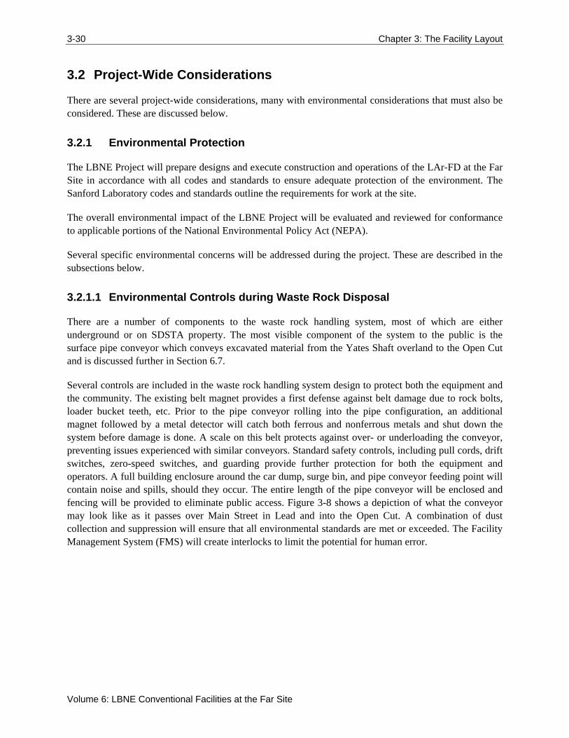
3-30 Chapter 3: The Facility Layout
Volume 6: LBNE Conventional Facilities at the Far Site
3.2 Project-Wide Considerations
There are several project-wide considerations, many with environmental considerations that must also be considered. These are discussed below.
3.2.1 Environmental Protection
The LBNE Project will prepare designs and execute construction and operations of the LAr-FD at the Far Site in accordance with all codes and standards to ensure adequate protection of the environment. The Sanford Laboratory codes and standards outline the requirements for work at the site.
The overall environmental impact of the LBNE Project will be evaluated and reviewed for conformance to applicable portions of the National Environmental Policy Act (NEPA).
Several specific environmental concerns will be addressed during the project. These are described in the subsections below.
3.2.1.1 Environmental Controls during Waste Rock Disposal
There are a number of components to the waste rock handling system, most of which are either underground or on SDSTA property. The most visible component of the system to the public is the surface pipe conveyor which conveys excavated material from the Yates Shaft overland to the Open Cut and is discussed further in Section 6.7.
Several controls are included in the waste rock handling system design to protect both the equipment and the community. The existing belt magnet provides a first defense against belt damage due to rock bolts, loader bucket teeth, etc. Prior to the pipe conveyor rolling into the pipe configuration, an additional magnet followed by a metal detector will catch both ferrous and nonferrous metals and shut down the system before damage is done. A scale on this belt protects against over- or underloading the conveyor, preventing issues experienced with similar conveyors. Standard safety controls, including pull cords, drift switches, zero-speed switches, and guarding provide further protection for both the equipment and operators. A full building enclosure around the car dump, surge bin, and pipe conveyor feeding point will contain noise and spills, should they occur. The entire length of the pipe conveyor will be enclosed and fencing will be provided to eliminate public access. Figure 3-8 shows a depiction of what the conveyor may look like as it passes over Main Street in Lead and into the Open Cut. A combination of dust collection and suppression will ensure that all environmental standards are met or exceeded. The Facility Management System (FMS) will create interlocks to limit the potential for human error.
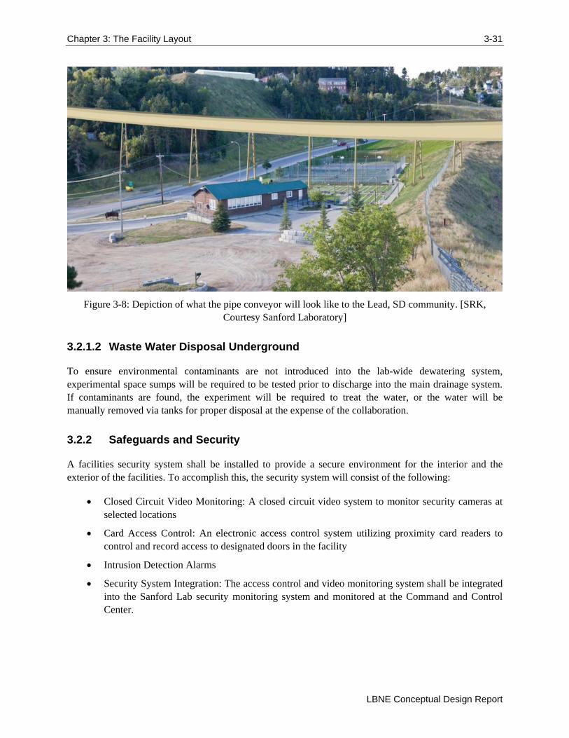
Chapter 3: The Facility Layout 3-31
LBNE Conceptual Design Report
Figure 3-8: Depiction of what the pipe conveyor will look like to the Lead, SD community. [SRK, Courtesy Sanford Laboratory]
3.2.1.2 Waste Water Disposal Underground
To ensure environmental contaminants are not introduced into the lab-wide dewatering system, experimental space sumps will be required to be tested prior to discharge into the main drainage system. If contaminants are found, the experiment will be required to treat the water, or the water will be manually removed via tanks for proper disposal at the expense of the collaboration.
3.2.2 Safeguards and Security
A facilities security system shall be installed to provide a secure environment for the interior and the exterior of the facilities. To accomplish this, the security system will consist of the following:
Closed Circuit Video Monitoring: A closed circuit video system to monitor security cameras at selected locations
Card Access Control: An electronic access control system utilizing proximity card readers to control and record access to designated doors in the facility
Intrusion Detection Alarms
Security System Integration: The access control and video monitoring system shall be integrated into the Sanford Lab security monitoring system and monitored at the Command and Control Center.
3-32 Chapter 3: The Facility Layout
Volume 6: LBNE Conventional Facilities at the Far Site
3.2.3 Emergency Shelter Provisions
Guidelines established by the Federal Emergency Management Agency (FEMA) in publications TR-83A and TR-83B and referenced in Section 0111-2.5, DOE 6430.1A may, if determined to be applicable, be used to assess the design of the buildings to insure safe areas within the buildings for the protection of the occupants. These protected areas would also serve as dual-purpose spaces with regard to protection during a national emergency in accordance with the direction given in Section 0110-10, DOE 6430.1A.
FEMA guidelines indicate that protected areas are:
on the lowest floor of a surface building
in an interior space, avoiding spaces with glass partitions
areas with short spans of the floor or roof structure are best; small rooms are usually safe, large rooms are to be avoided.
3.2.4 Energy Conservation
The DOE directive, Guiding Principles of High-Performance Building Design, is being assessed to determine applicability of how it may, or may not, be incorporated into the design of the LBNE Conventional Facilities. However, discussions are ongoing regarding the applicability of the guiding principles based on the ownership/stewardship of the Sanford Laboratory, the type and use of the facilities. If applicable, LBNE processes and each project element will be evaluated during design to reduce their impact on natural resources without sacrificing program objectives. The project design will incorporate maintainability, aesthetics, environmental justice, and program requirements as required to deliver a well-balanced project.
As applicable, elements of this project may be reviewed for energy conservation features that can be effectively incorporated into the overall building design. Energy conservation techniques and high efficiency equipment will be utilized wherever appropriate to minimize the total energy consumption.
3.2.5 DOE Space Allocation
The elimination of excess facility capacity is an ongoing effort at all DOE programs. Eliminating excess facilities (buildings) to offset new building construction (on a building square foot basis) frees up future budget resources for maintaining and recapitalizing DOE’s remaining facilities.
The LBNE Near Site project has obtained a DOE Space Allocation/Space Bank waiver, meaning that there is sufficient elimination of excess facilities capacity elsewhere in DOE labs to offset the new LBNE building square footage. The ultimate applicability of these DOE requirements to the Far Site will be determined as the ownership/stewardship model of the Far Site is determined.
Chapter 4: Surface Buildings 4-33
LBNE Conceptual Design Report
4 Surface Buildings
Surface facilities utilized for the LAr-FD include those necessary for safe access and egress to the underground through the Ross and Yates Shafts, as well as spaces for temporary offices (by Sanford Laboratory) and temporary warehousing of experiment installation parts and equipment. Existing buildings will be rehabilitated to code-compliance and to provide for the needs of the experiment. The only new buildings will be for cryogen purity testing and shaft access at the Oro Hondo site, and the temporary warehouse for experiment installation.
4.1 Ross Headframe and Hoist Buildings (WBS 130.06.05.05.02.04.02)
The headframe and hoist buildings at the Ross Campus require exterior rehabilitation to provide a warm, usable shell. The Ross Headframe Building will be the main entry point for construction activities as well as the ongoing operations and maintenance functions. The Ross Hoist Building and Ross Headframe are pictured in Figure 4-1 and Figure 4-2.
Figure 4-1: Photo of Ross Hoist exterior. [HDR]
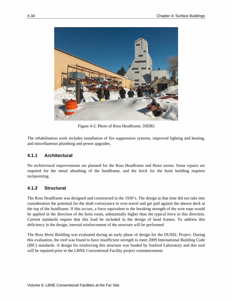
4-34 Chapter 4: Surface Buildings
Volume 6: LBNE Conventional Facilities at the Far Site
Figure 4-2: Photo of Ross Headframe. [HDR]
The rehabilitation work includes installation of fire suppression systems, improved lighting and heating, and miscellaneous plumbing and power upgrades.
4.1.1 Architectural
No architectural improvements are planned for the Ross Headframe and Hoist rooms. Some repairs are required for the metal sheathing of the headframe, and the brick for the hoist building requires tuckpointing.
4.1.2 Structural
The Ross Headframe was designed and constructed in the 1930’s. The design at that time did not take into consideration the potential for the shaft conveyance to over-travel and get pull against the sheave deck at the top of the headframe. If this occurs, a force equivalent to the breaking strength of the wire rope would be applied in the direction of the hoist room, substantially higher than the typical force in this direction. Current standards require that this load be included in the design of head frames. To address this deficiency in the design, internal reinforcement of the structure will be performed.
The Ross Hoist Building was evaluated during an early phase of design for the DUSEL Project. During this evaluation, the roof was found to have insufficient strength to meet 2009 International Building Code (IBC) standards. A design for reinforcing this structure was funded by Sanford Laboratory and this roof will be repaired prior to the LBNE Conventional Facility project commencement.
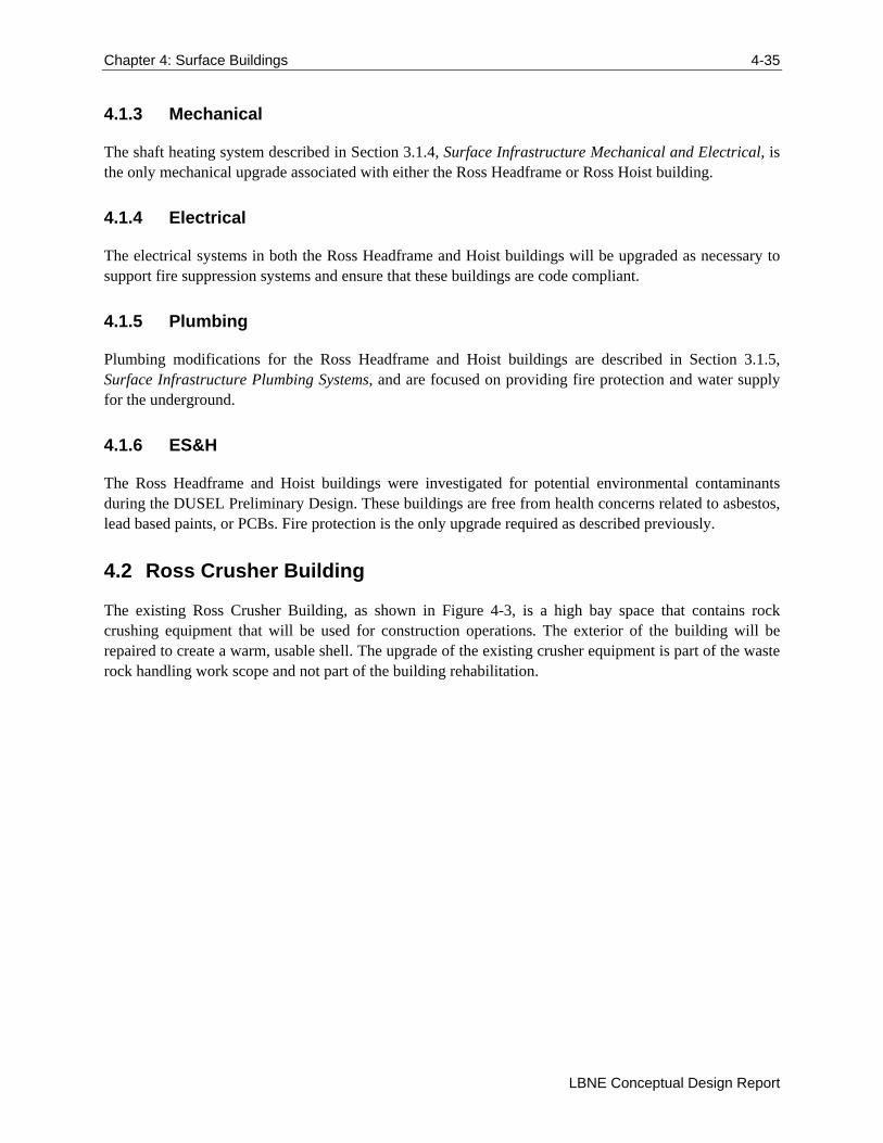
Chapter 4: Surface Buildings 4-35
LBNE Conceptual Design Report
4.1.3 Mechanical
The shaft heating system described in Section 3.1.4, Surface Infrastructure Mechanical and Electrical, is the only mechanical upgrade associated with either the Ross Headframe or Ross Hoist building.
4.1.4 Electrical
The electrical systems in both the Ross Headframe and Hoist buildings will be upgraded as necessary to support fire suppression systems and ensure that these buildings are code compliant.
4.1.5 Plumbing
Plumbing modifications for the Ross Headframe and Hoist buildings are described in Section 3.1.5, Surface Infrastructure Plumbing Systems, and are focused on providing fire protection and water supply for the underground.
4.1.6 ES&H
The Ross Headframe and Hoist buildings were investigated for potential environmental contaminants during the DUSEL Preliminary Design. These buildings are free from health concerns related to asbestos, lead based paints, or PCBs. Fire protection is the only upgrade required as described previously.
4.2 Ross Crusher Building
The existing Ross Crusher Building, as shown in Figure 4-3, is a high bay space that contains rock crushing equipment that will be used for construction operations. The exterior of the building will be repaired to create a warm, usable shell. The upgrade of the existing crusher equipment is part of the waste rock handling work scope and not part of the building rehabilitation.
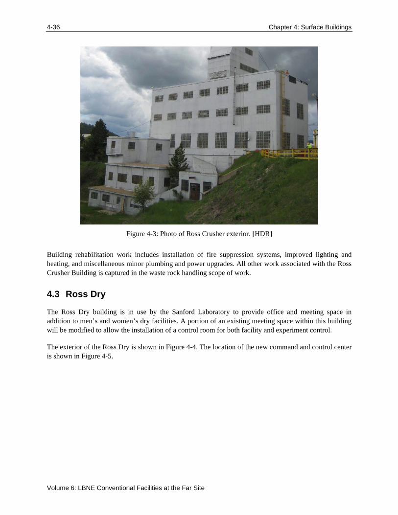
4-36 Chapter 4: Surface Buildings
Volume 6: LBNE Conventional Facilities at the Far Site
Figure 4-3: Photo of Ross Crusher exterior. [HDR]
Building rehabilitation work includes installation of fire suppression systems, improved lighting and heating, and miscellaneous minor plumbing and power upgrades. All other work associated with the Ross Crusher Building is captured in the waste rock handling scope of work.
4.3 Ross Dry
The Ross Dry building is in use by the Sanford Laboratory to provide office and meeting space in addition to men’s and women’s dry facilities. A portion of an existing meeting space within this building will be modified to allow the installation of a control room for both facility and experiment control.
The exterior of the Ross Dry is shown in Figure 4-4. The location of the new command and control center is shown in Figure 4-5.
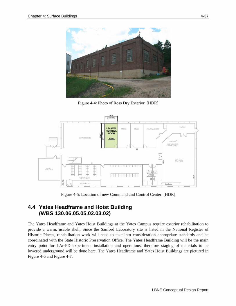
Chapter 4: Surface Buildings 4-37
LBNE Conceptual Design Report
Figure 4-4: Photo of Ross Dry Exterior. [HDR]
Figure 4-5: Location of new Command and Control Center. [HDR]
4.4 Yates Headframe and Hoist Building (WBS 130.06.05.05.02.03.02)
The Yates Headframe and Yates Hoist Buildings at the Yates Campus require exterior rehabilitation to provide a warm, usable shell. Since the Sanford Laboratory site is listed in the National Register of Historic Places, rehabilitation work will need to take into consideration appropriate standards and be coordinated with the State Historic Preservation Office. The Yates Headframe Building will be the main entry point for LAr-FD experiment installation and operations, therefore staging of materials to be lowered underground will be done here. The Yates Headframe and Yates Hoist Buildings are pictured in Figure 4-6 and Figure 4-7.
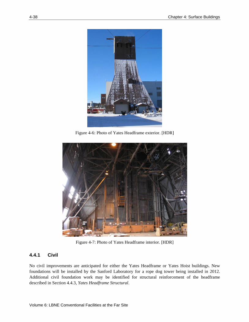
4-38 Chapter 4: Surface Buildings
Volume 6: LBNE Conventional Facilities at the Far Site
Figure 4-6: Photo of Yates Headframe exterior. [HDR]
Figure 4-7: Photo of Yates Headframe interior. [HDR]
4.4.1 Civil
No civil improvements are anticipated for either the Yates Headframe or Yates Hoist buildings. New foundations will be installed by the Sanford Laboratory for a rope dog tower being installed in 2012. Additional civil foundation work may be identified for structural reinforcement of the headframe described in Section 4.4.3, Yates Headframe Structural.
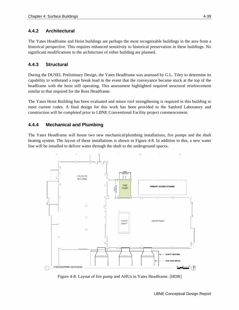
Chapter 4: Surface Buildings 4-39
LBNE Conceptual Design Report
4.4.2 Architectural
The Yates Headframe and Hoist buildings are perhaps the most recognizable buildings in the area from a historical perspective. This requires enhanced sensitivity to historical preservation in these buildings. No significant modifications to the architecture of either building are planned.
4.4.3 Structural
During the DUSEL Preliminary Design, the Yates Headframe was assessed by G.L. Tiley to determine its capability to withstand a rope break load in the event that the conveyance became stuck at the top of the headframe with the hoist still operating. This assessment highlighted required structural reinforcement similar to that required for the Ross Headframe.
The Yates Hoist Building has been evaluated and minor roof strengthening is required in this building to meet current codes. A final design for this work has been provided to the Sanford Laboratory and construction will be completed prior to LBNE Conventional Facility project commencement.
4.4.4 Mechanical and Plumbing
The Yates Headframe will house two new mechanical/plumbing installations, fire pumps and the shaft heating system. The layout of these installations is shown in Figure 4-8. In addition to this, a new water line will be installed to deliver water through the shaft to the underground spaces.
Figure 4-8: Layout of fire pump and AHUs in Yates Headframe. [HDR]
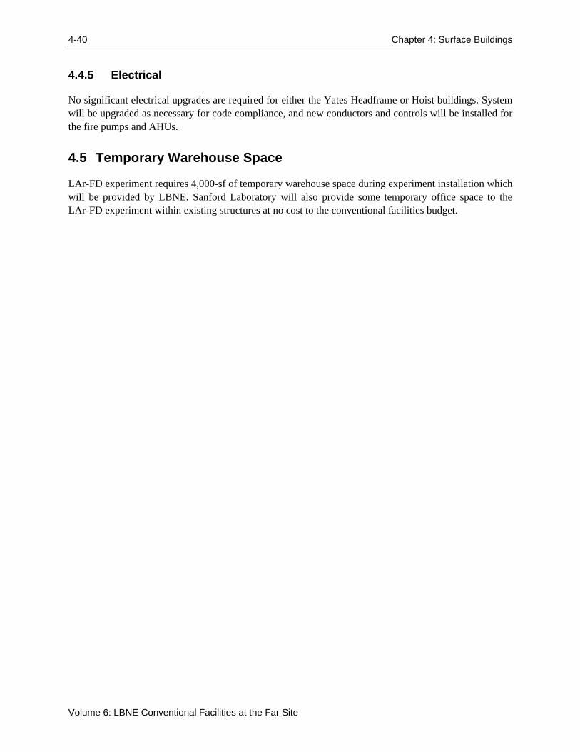
4-40 Chapter 4: Surface Buildings
Volume 6: LBNE Conventional Facilities at the Far Site
4.4.5 Electrical
No significant electrical upgrades are required for either the Yates Headframe or Hoist buildings. System will be upgraded as necessary for code compliance, and new conductors and controls will be installed for the fire pumps and AHUs.
4.5 Temporary Warehouse Space
LAr-FD experiment requires 4,000-sf of temporary warehouse space during experiment installation which will be provided by LBNE. Sanford Laboratory will also provide some temporary office space to the LAr-FD experiment within existing structures at no cost to the conventional facilities budget.
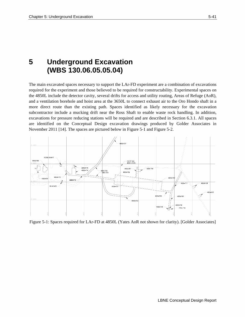
Chapter 5: Underground Excavation 5-41
LBNE Conceptual Design Report
5 Underground Excavation (WBS 130.06.05.05.04)
The main excavated spaces necessary to support the LAr-FD experiment are a combination of excavations required for the experiment and those believed to be required for constructability. Experimental spaces on the 4850L include the detector cavity, several drifts for access and utility routing, Areas of Refuge (AoR), and a ventilation borehole and hoist area at the 3650L to connect exhaust air to the Oro Hondo shaft in a more direct route than the existing path. Spaces identified as likely necessary for the excavation subcontractor include a mucking drift near the Ross Shaft to enable waste rock handling. In addition, excavations for pressure reducing stations will be required and are described in Section 6.3.1. All spaces are identified on the Conceptual Design excavation drawings produced by Golder Associates in November 2011 [14]. The spaces are pictured below in Figure 5-1 and Figure 5-2.
Figure 5-1: Spaces required for LAr-FD at 4850L (Yates AoR not shown for clarity). [Golder Associates]
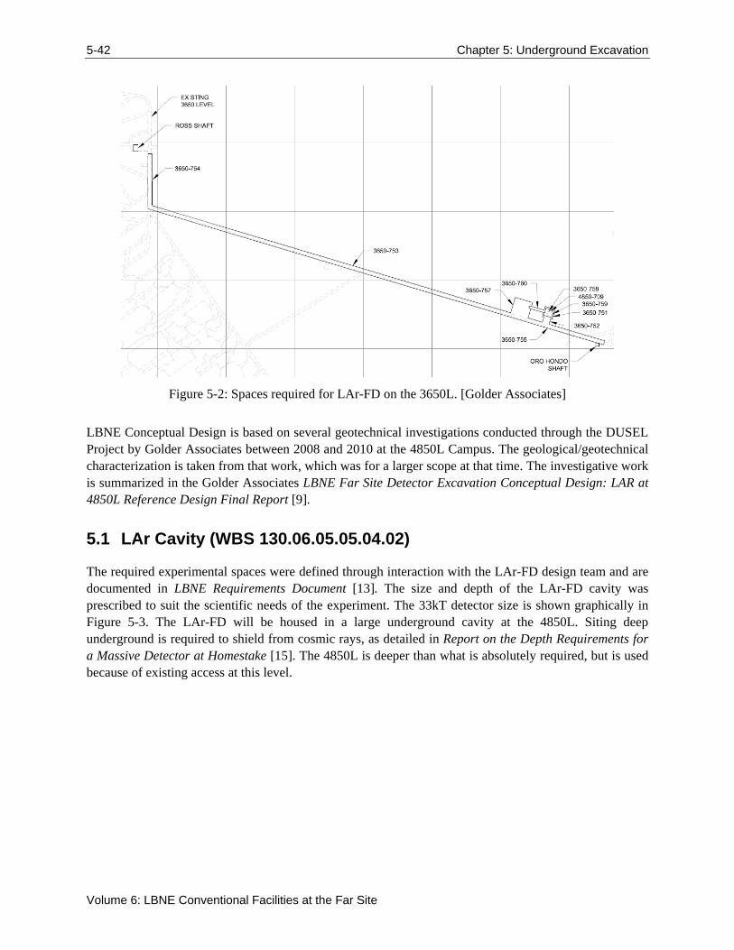
5-42 Chapter 5: Underground Excavation
Volume 6: LBNE Conventional Facilities at the Far Site
Figure 5-2: Spaces required for LAr-FD on the 3650L. [Golder Associates]
LBNE Conceptual Design is based on several geotechnical investigations conducted through the DUSEL Project by Golder Associates between 2008 and 2010 at the 4850L Campus. The geological/geotechnical characterization is taken from that work, which was for a larger scope at that time. The investigative work is summarized in the Golder Associates LBNE Far Site Detector Excavation Conceptual Design: LAR at 4850L Reference Design Final Report [9].
5.1 LAr Cavity (WBS 130.06.05.05.04.02)
The required experimental spaces were defined through interaction with the LAr-FD design team and are documented in LBNE Requirements Document [13]. The size and depth of the LAr-FD cavity was prescribed to suit the scientific needs of the experiment. The 33kT detector size is shown graphically in Figure 5-3. The LAr-FD will be housed in a large underground cavity at the 4850L. Siting deep underground is required to shield from cosmic rays, as detailed in Report on the Depth Requirements for a Massive Detector at Homestake [15]. The 4850L is deeper than what is absolutely required, but is used because of existing access at this level.
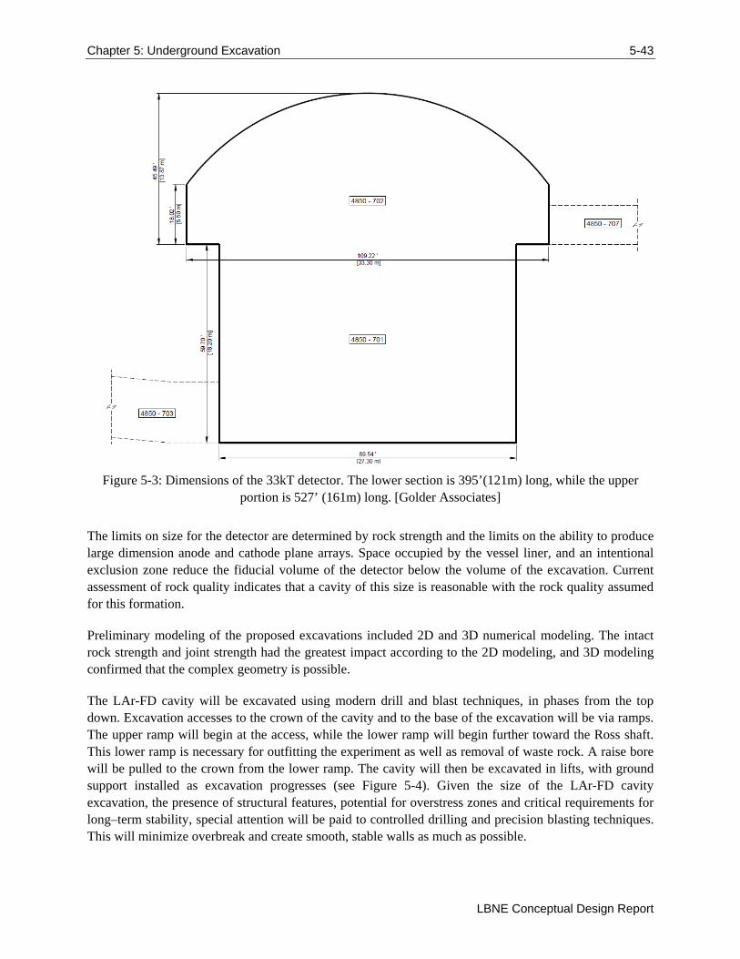
Chapter 5: Underground Excavation 5-43
LBNE Conceptual Design Report
Figure 5-3: Dimensions of the 33kT detector. The lower section is 395’(121m) long, while the upper portion is 527’ (161m) long. [Golder Associates]
The limits on size for the detector are determined by rock strength and the limits on the ability to produce large dimension anode and cathode plane arrays. Space occupied by the vessel liner, and an intentional exclusion zone reduce the fiducial volume of the detector below the volume of the excavation. Current assessment of rock quality indicates that a cavity of this size is reasonable with the rock quality assumed for this formation.
Preliminary modeling of the proposed excavations included 2D and 3D numerical modeling. The intact rock strength and joint strength had the greatest impact according to the 2D modeling, and 3D modeling confirmed that the complex geometry is possible.
The LAr-FD cavity will be excavated using modern drill and blast techniques, in phases from the top down. Excavation accesses to the crown of the cavity and to the base of the excavation will be via ramps. The upper ramp will begin at the access, while the lower ramp will begin further toward the Ross shaft. This lower ramp is necessary for outfitting the experiment as well as removal of waste rock. A raise bore will be pulled to the crown from the lower ramp. The cavity will then be excavated in lifts, with ground support installed as excavation progresses (see Figure 5-4). Given the size of the LAr-FD cavity excavation, the presence of structural features, potential for overstress zones and critical requirements for long–term stability, special attention will be paid to controlled drilling and precision blasting techniques. This will minimize overbreak and create smooth, stable walls as much as possible.
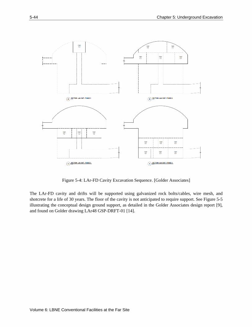
5-44 Chapter 5: Underground Excavation
Volume 6: LBNE Conventional Facilities at the Far Site
Figure 5-4: LAr-FD Cavity Excavation Sequence. [Golder Associates]
The LAr-FD cavity and drifts will be supported using galvanized rock bolts/cables, wire mesh, and shotcrete for a life of 30 years. The floor of the cavity is not anticipated to require support. See Figure 5-5 illustrating the conceptual design ground support, as detailed in the Golder Associates design report [9], and found on Golder drawing LAr48 GSP-DRFT-01 [14].
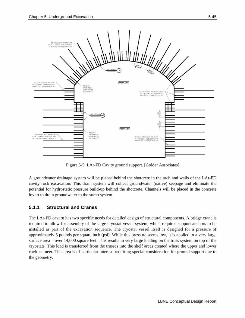
Chapter 5: Underground Excavation 5-45
LBNE Conceptual Design Report
Figure 5-5: LAr-FD Cavity ground support. [Golder Associates]
A groundwater drainage system will be placed behind the shotcrete in the arch and walls of the LAr-FD cavity rock excavation. This drain system will collect groundwater (native) seepage and eliminate the potential for hydrostatic pressure build-up behind the shotcrete. Channels will be placed in the concrete invert to drain groundwater to the sump system.
5.1.1 Structural and Cranes
The LAr-FD cavern has two specific needs for detailed design of structural components. A bridge crane is required to allow for assembly of the large cryostat vessel system, which requires support anchors to be installed as part of the excavation sequence. The cryostat vessel itself is designed for a pressure of approximately 5 pounds per square inch (psi). While this pressure seems low, it is applied to a very large surface area – over 14,000 square feet. This results in very large loading on the truss system on top of the cryostats. This load is transferred from the trusses into the shelf areas created where the upper and lower cavities meet. This area is of particular interest, requiring special consideration for ground support due to the geometry.
5-46 Chapter 5: Underground Excavation
Volume 6: LBNE Conventional Facilities at the Far Site
5.2 LAr-FD Upper Cavity
The LAr-FD experiment requires spaces for experimental equipment outside of the cavity. These requirements have been combined with that for the MEP utilities in the upper chamber of the cavity. These areas will house the experiment’s cryogen system, electrical equipment to supply power for facility and experiment needs, sump pump access and controls, fire sprinkler room, air handling units (AHUs), chilled water system, and exhaust ducting.
5.3 Access/Egress Drifts (WBS 130.06.05.05.04.01)
After the Yates Shaft rehabilitation is complete, the Yates Shaft may become the primary experimental access for the delivery of materials and equipment and the Ross Shaft may be used for personnel access to and egress from the underground. The existing West Access Drift must be enlarged to accommodate installation of utilities. This enlargement will also allow either shaft to be used for conveyance of materials and equipment since this drift will become a main access passageway from the Yates Shaft. Secondary egress from the cavity extends from the center of the cavity to the existing south drift on the 4850L. From this location, egress paths exist to either the Ross or Yates Shafts.
Life safety requirements also dictate provision for areas of refuge at specific locations throughout the occupied areas. AoRs are provided at the base of the Yates and Ross Shafts, in the secondary egress path, and in the West Access Drift.
5.4 Interfaces between LAr-FD and Excavation
There are several points at which the experiment and the facility interface closely. These are managed through discussions between LAr-FD design team and the Conventional Facilities Level 3 managers and design consultants.
The LAr-FD concrete vessel and heating system is placed directly against the excavated rock. Low tolerance control in excavation will impact the cost of installing this vessel.
The LAr-FD roof truss supports connect directly to the rock at the “shoulder” where the upper and lower cavities meet. This requires good excavation elevation grade control as well as substantial ground support for the resultant loads.
The utility spaces to house the cryogen system are directly influenced by the size of the cryogen system equipment.
Chapter 6: Underground Infrastructure 6-47
LBNE Conceptual Design Report
6 Underground Infrastructure (WBS 130.06.05.05.03)
The requirements for underground infrastructure for the LBNE Project will be satisfied by a combination of existing infrastructure, improvements to those systems, and development of new infrastructure to suit specific needs. The Project assumes that the only other tenant underground at Sanford Laboratory for which infrastructure is required is the existing Davis Campus experiments.
The systems will support the Conventional Facilities (CF) construction activities, CF designed to support the experiment, and the LAr-FD experiment installation and operations. The three scenarios were analyzed and the most demanding requirements chosen from each situation were used to define the requirements for design.
Some of the Sanford Laboratory infrastructure that requires upgrading for LBNE will be rehabilitated prior to the beginning of LBNE construction funding. This work is important for LBNE, but is considered not part of the LBNE Project scope. This includes Ross Shaft rehabilitation, Yates Shaft rope dog installation, Hoist Buildings’ roof strengthening, and Headframe Buildings’ structural upgrades. This work is expected to be performed using non-project funding, and will be discussed in this CDR as it is pertinent to the LBNE Project.
The conceptual underground infrastructure design for LAr-FD has been performed by several entities. The primary designer referenced in this document is Arup, USA. Arup’s scope includes utility provisions and fire/life safety (FLS) strategy, covering infrastructure from the surface through the shafts and drifts, to the cavity excavations for the experiment. Utility infrastructure includes fire/life safety systems, permanent ventilation guidance, HVAC, power, plumbing systems, communications infrastructure, lighting and controls, per the experimental utility requirements provided by LAr-FD and through coordination with LBNE, Sanford Laboratory and the excavation and surface design teams. The design is described in Arup’s LBNE 100% Concept Design Report for LAr at 4850L [16] and in the conceptual design drawings [17]. This chapter summarizes the work done by Arup and utilizes information from that report.
Shaft rehabilitation and waste rock handling design were previously provided by Arup for the DUSEL PDR. This chapter uses excerpts from the DUSEL Preliminary Design Report, Chapter 5.4. The research supporting this work took place in whole or in part at the Sanford Underground Laboratory at Homestake in Lead, South Dakota. Funding for this work was provided by the National Science Foundation through Cooperative Agreements PHY-0717003 and PHY-0940801. The assistance of the Sanford Underground Laboratory at Homestake and its personnel in providing physical access and general logistical and technical support is acknowledged.
6-48 Chapter 6: Underground Infrastructure
Volume 6: LBNE Conventional Facilities at the Far Site
6.1 Fire/Life Safety Systems (WBS 130.06.05.05.03.05)
Life safety is a significant design criterion for underground facilities, focusing on events that could impact the ability to safely escape, or if escape is not immediately possible, isolate people from events underground. Design for fire events includes both preventing spread of fire and removing smoke through the ventilation system.
Life safety requirements were identified and the design developed by Arup, utilizing applicable codes and standards, including NFPA 520: Standard on Subterranean Spaces, which requires adequate egress in the event of an emergency. Facility fire detection and suppression systems, as well as personnel occupancy requirements are defined in accordance with NFPA 101: Life Safety Code. The design was reviewed by Aon Risk Solutions and the recommendations documented in Fire Protection/Life Safety Assessment for the Conceptual Design of the Far Site of the Long Baseline Neutrino Experiment [18].
Based on data provided by Sanford Laboratory the maximum occupant load of the 4850L will be 101 occupants. This includes 42 Underground Operations staff, 50 science staff for LAr-FD (during installation), and 9 science staff associated with the Davis Cavity.
Compartmentation will be needed for egress routes to separate them from adjacent spaces to limit the horizontal and vertical spread of fire and smoke. Use of compartmentation will help to reduce the likelihood of fire and smoke spreading from the area of fire origin to other areas or compartments. Compartmentation will also help limit the spread of other materials such as cryogenic gases, leaks and spills. This results in design criteria of minimum 4-hour fire separation between the LAr-FD cavity and adjacent drifts, while all rooms that connect directly to the egress drift at 4850L, as well as the shafts, will have 2-hour minimum fire separation.
6.1.1 Egress and Areas of Refuge
The evacuation strategy for occupants at the 4850L is to egress directly to the Yates Hoist/Cage (or Ross Hoist/Cage if the Yates Hoist/Cage is not working or inaccessible) to evacuate to grade. If occupants are subjected to untenable conditions within the egress route, then they will need to evacuate to the alternate hoist/cage or to their nearest Area of Refuge (AoR). There will be a minimum of two ways out of the LAr-FD Cavity and areas of high hazard. Once in a drift (exit route) there will be at least two directions to escape from any location leading to a choice of exit hoist/cage.
AoRs provide a protected environment for occupants during an emergency event, such as a fire or cryogen leak. AoRs are strategically located within the 4850L such that the travel distance to an area of refuge is limited to within the NFPA 520 maximum travel distance of 2,000 ft. AoRs are to be located at each of the hoistways/cages (i.e. Yates Shaft and Ross Shaft), where people are working (i.e. LAr-FD Cavity), and intermittently throughout the 4850L (i.e. within the drifts). AoR area calculations use a baseline area of 10 sf/person, derived from NFPA 520.
6.1.2 Emergency Systems
Systems will be installed to facilitate egress for life safety and protect personnel and equipment during emergencies. This includes fire suppressions systems, smoke control, alarm and detection systems, two-
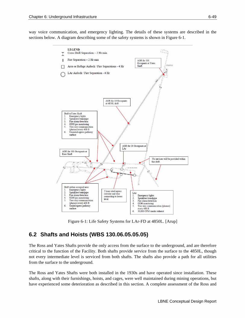
Chapter 6: Underground Infrastructure 6-49
LBNE Conceptual Design Report
way voice communication, and emergency lighting. The details of these systems are described in the sections below. A diagram describing some of the safety systems is shown in Figure 6-1.
Figure 6-1: Life Safety Systems for LAr-FD at 4850L. [Arup]
6.2 Shafts and Hoists (WBS 130.06.05.05.05)
The Ross and Yates Shafts provide the only access from the surface to the underground, and are therefore critical to the function of the Facility. Both shafts provide service from the surface to the 4850L, though not every intermediate level is serviced from both shafts. The shafts also provide a path for all utilities from the surface to the underground.
The Ross and Yates Shafts were both installed in the 1930s and have operated since installation. These shafts, along with their furnishings, hoists, and cages, were well maintained during mining operations, but have experienced some deterioration as described in this section. A complete assessment of the Ross and
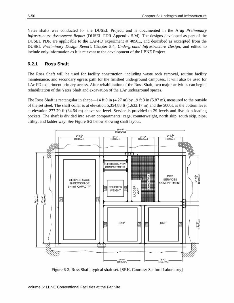
6-50 Chapter 6: Underground Infrastructure
Volume 6: LBNE Conventional Facilities at the Far Site
Yates shafts was conducted for the DUSEL Project, and is documented in the Arup Preliminary Infrastructure Assessment Report (DUSEL PDR Appendix 5.M). The designs developed as part of the DUSEL PDR are applicable to the LAr-FD experiment at 4850L, and described as excerpted from the DUSEL Preliminary Design Report, Chapter 5.4, Underground Infrastructure Design, and edited to include only information as it is relevant to the development of the LBNE Project.
6.2.1 Ross Shaft
The Ross Shaft will be used for facility construction, including waste rock removal, routine facility maintenance, and secondary egress path for the finished underground campuses. It will also be used for LAr-FD experiment primary access. After rehabilitation of the Ross Shaft, two major activities can begin; rehabilitation of the Yates Shaft and excavation of the LAr underground spaces.
The Ross Shaft is rectangular in shape—14 ft 0 in (4.27 m) by 19 ft 3 in (5.87 m), measured to the outside of the set steel. The shaft collar is at elevation 5,354.88 ft (1,632.17 m) and the 5000L is the bottom level at elevation 277.70 ft (84.64 m) above sea level. Service is provided to 29 levels and five skip loading pockets. The shaft is divided into seven compartments: cage, counterweight, north skip, south skip, pipe, utility, and ladder way. See Figure 6-2 below showing shaft layout.
Figure 6-2: Ross Shaft, typical shaft set. [SRK, Courtesy Sanford Laboratory]
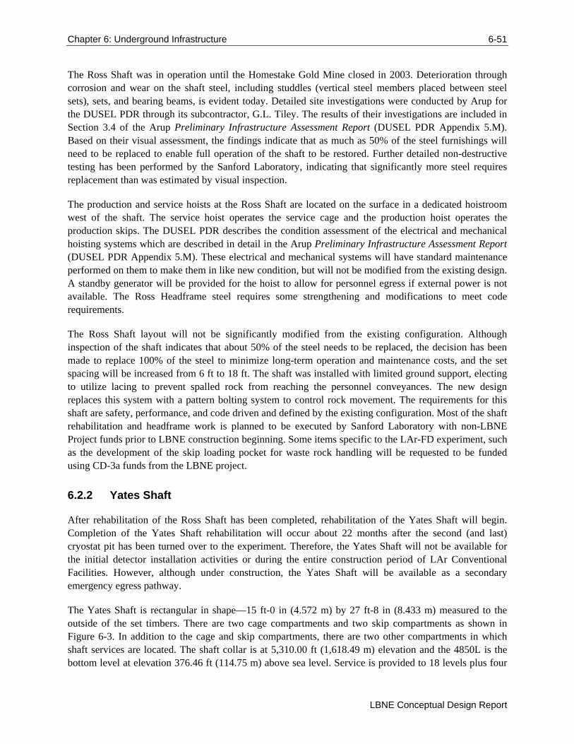
Chapter 6: Underground Infrastructure 6-51
LBNE Conceptual Design Report
The Ross Shaft was in operation until the Homestake Gold Mine closed in 2003. Deterioration through corrosion and wear on the shaft steel, including studdles (vertical steel members placed between steel sets), sets, and bearing beams, is evident today. Detailed site investigations were conducted by Arup for the DUSEL PDR through its subcontractor, G.L. Tiley. The results of their investigations are included in Section 3.4 of the Arup Preliminary Infrastructure Assessment Report (DUSEL PDR Appendix 5.M). Based on their visual assessment, the findings indicate that as much as 50% of the steel furnishings will need to be replaced to enable full operation of the shaft to be restored. Further detailed non-destructive testing has been performed by the Sanford Laboratory, indicating that significantly more steel requires replacement than was estimated by visual inspection.
The production and service hoists at the Ross Shaft are located on the surface in a dedicated hoistroom west of the shaft. The service hoist operates the service cage and the production hoist operates the production skips. The DUSEL PDR describes the condition assessment of the electrical and mechanical hoisting systems which are described in detail in the Arup Preliminary Infrastructure Assessment Report (DUSEL PDR Appendix 5.M). These electrical and mechanical systems will have standard maintenance performed on them to make them in like new condition, but will not be modified from the existing design. A standby generator will be provided for the hoist to allow for personnel egress if external power is not available. The Ross Headframe steel requires some strengthening and modifications to meet code requirements.
The Ross Shaft layout will not be significantly modified from the existing configuration. Although inspection of the shaft indicates that about 50% of the steel needs to be replaced, the decision has been made to replace 100% of the steel to minimize long-term operation and maintenance costs, and the set spacing will be increased from 6 ft to 18 ft. The shaft was installed with limited ground support, electing to utilize lacing to prevent spalled rock from reaching the personnel conveyances. The new design replaces this system with a pattern bolting system to control rock movement. The requirements for this shaft are safety, performance, and code driven and defined by the existing configuration. Most of the shaft rehabilitation and headframe work is planned to be executed by Sanford Laboratory with non-LBNE Project funds prior to LBNE construction beginning. Some items specific to the LAr-FD experiment, such as the development of the skip loading pocket for waste rock handling will be requested to be funded using CD-3a funds from the LBNE project.
6.2.2 Yates Shaft
After rehabilitation of the Ross Shaft has been completed, rehabilitation of the Yates Shaft will begin. Completion of the Yates Shaft rehabilitation will occur about 22 months after the second (and last) cryostat pit has been turned over to the experiment. Therefore, the Yates Shaft will not be available for the initial detector installation activities or during the entire construction period of LAr Conventional Facilities. However, although under construction, the Yates Shaft will be available as a secondary emergency egress pathway.
The Yates Shaft is rectangular in shape—15 ft-0 in (4.572 m) by 27 ft-8 in (8.433 m) measured to the outside of the set timbers. There are two cage compartments and two skip compartments as shown in Figure 6-3. In addition to the cage and skip compartments, there are two other compartments in which shaft services are located. The shaft collar is at 5,310.00 ft (1,618.49 m) elevation and the 4850L is the bottom level at elevation 376.46 ft (114.75 m) above sea level. Service is provided to 18 levels plus four
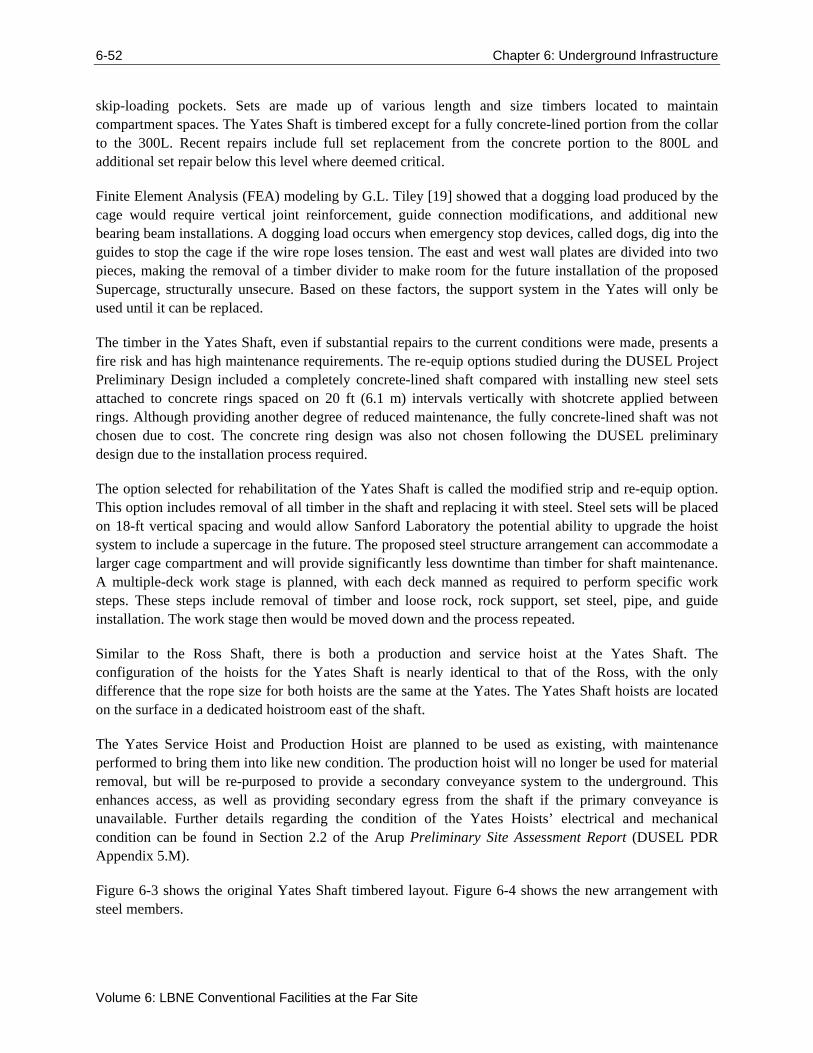
6-52 Chapter 6: Underground Infrastructure
Volume 6: LBNE Conventional Facilities at the Far Site
skip-loading pockets. Sets are made up of various length and size timbers located to maintain compartment spaces. The Yates Shaft is timbered except for a fully concrete-lined portion from the collar to the 300L. Recent repairs include full set replacement from the concrete portion to the 800L and additional set repair below this level where deemed critical.
Finite Element Analysis (FEA) modeling by G.L. Tiley [19] showed that a dogging load produced by the cage would require vertical joint reinforcement, guide connection modifications, and additional new bearing beam installations. A dogging load occurs when emergency stop devices, called dogs, dig into the guides to stop the cage if the wire rope loses tension. The east and west wall plates are divided into two pieces, making the removal of a timber divider to make room for the future installation of the proposed Supercage, structurally unsecure. Based on these factors, the support system in the Yates will only be used until it can be replaced.
The timber in the Yates Shaft, even if substantial repairs to the current conditions were made, presents a fire risk and has high maintenance requirements. The re-equip options studied during the DUSEL Project Preliminary Design included a completely concrete-lined shaft compared with installing new steel sets attached to concrete rings spaced on 20 ft (6.1 m) intervals vertically with shotcrete applied between rings. Although providing another degree of reduced maintenance, the fully concrete-lined shaft was not chosen due to cost. The concrete ring design was also not chosen following the DUSEL preliminary design due to the installation process required.
The option selected for rehabilitation of the Yates Shaft is called the modified strip and re-equip option. This option includes removal of all timber in the shaft and replacing it with steel. Steel sets will be placed on 18-ft vertical spacing and would allow Sanford Laboratory the potential ability to upgrade the hoist system to include a supercage in the future. The proposed steel structure arrangement can accommodate a larger cage compartment and will provide significantly less downtime than timber for shaft maintenance. A multiple-deck work stage is planned, with each deck manned as required to perform specific work steps. These steps include removal of timber and loose rock, rock support, set steel, pipe, and guide installation. The work stage then would be moved down and the process repeated.
Similar to the Ross Shaft, there is both a production and service hoist at the Yates Shaft. The configuration of the hoists for the Yates Shaft is nearly identical to that of the Ross, with the only difference that the rope size for both hoists are the same at the Yates. The Yates Shaft hoists are located on the surface in a dedicated hoistroom east of the shaft.
The Yates Service Hoist and Production Hoist are planned to be used as existing, with maintenance performed to bring them into like new condition. The production hoist will no longer be used for material removal, but will be re-purposed to provide a secondary conveyance system to the underground. This enhances access, as well as providing secondary egress from the shaft if the primary conveyance is unavailable. Further details regarding the condition of the Yates Hoists’ electrical and mechanical condition can be found in Section 2.2 of the Arup Preliminary Site Assessment Report (DUSEL PDR Appendix 5.M).
Figure 6-3 shows the original Yates Shaft timbered layout. Figure 6-4 shows the new arrangement with steel members.
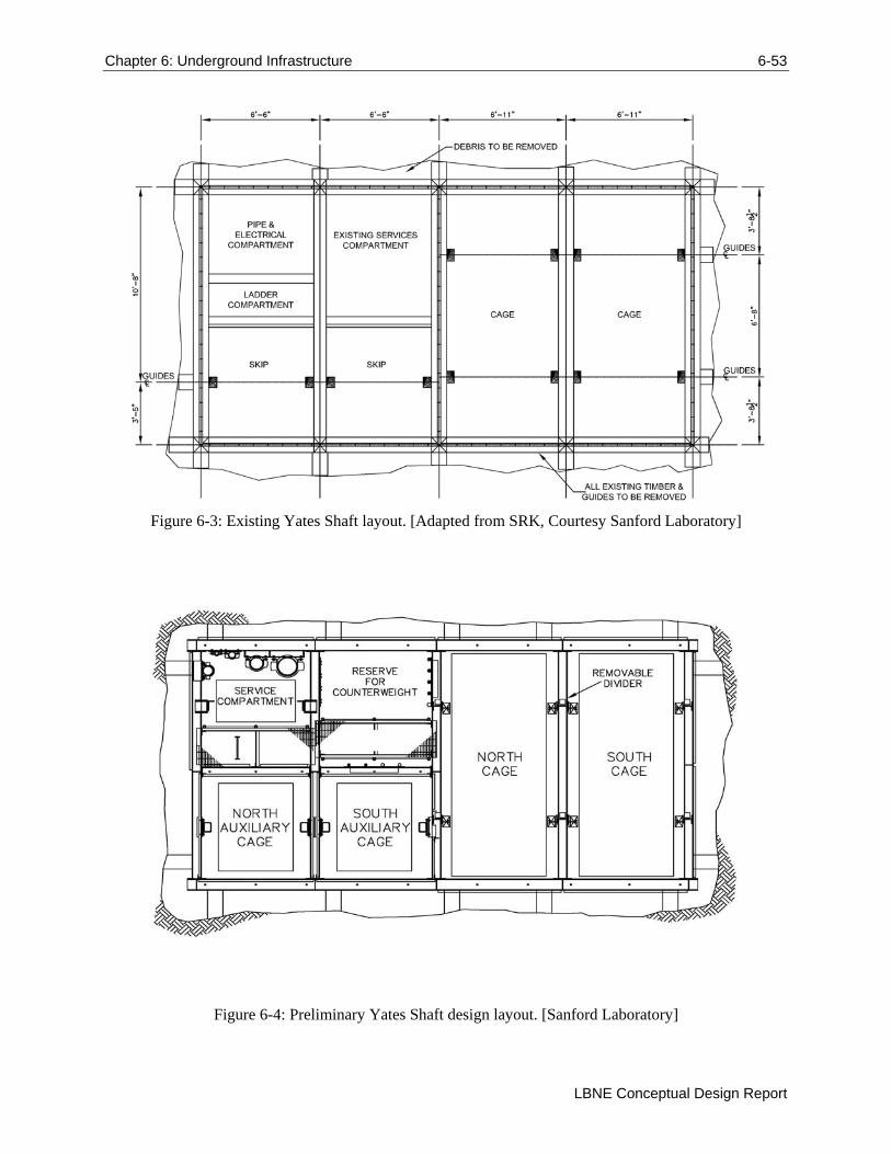
Chapter 6: Underground Infrastructure 6-53
LBNE Conceptual Design Report
Figure 6-3: Existing Yates Shaft layout. [Adapted from SRK, Courtesy Sanford Laboratory]
Figure 6-4: Preliminary Yates Shaft design layout. [Sanford Laboratory]
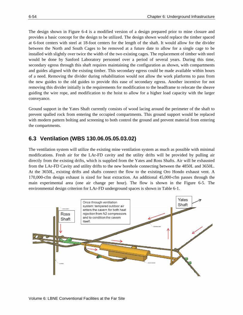
6-54 Chapter 6: Underground Infrastructure
Volume 6: LBNE Conventional Facilities at the Far Site
The design shown in Figure 6-4 is a modified version of a design prepared prior to mine closure and provides a basic concept for the design to be utilized. The design shown would replace the timber spaced at 6-foot centers with steel at 18-foot centers for the length of the shaft. It would allow for the divider between the North and South Cages to be removed at a future date to allow for a single cage to be installed with slightly over twice the width of the two existing cages. The replacement of timber with steel would be done by Sanford Laboratory personnel over a period of several years. During this time, secondary egress through this shaft requires maintaining the configuration as shown, with compartments and guides aligned with the existing timber. This secondary egress could be made available within hours of a need. Removing the divider during rehabilitation would not allow the work platforms to pass from the new guides to the old guides to provide this ease of secondary egress. Another incentive for not removing this divider initially is the requirements for modification to the headframe to relocate the sheave guiding the wire rope, and modification to the hoist to allow for a higher load capacity with the larger conveyance.
Ground support in the Yates Shaft currently consists of wood lacing around the perimeter of the shaft to prevent spalled rock from entering the occupied compartments. This ground support would be replaced with modern pattern bolting and screening to both control the ground and prevent material from entering the compartments.
6.3 Ventilation (WBS 130.06.05.05.03.02)
The ventilation system will utilize the existing mine ventilation system as much as possible with minimal modifications. Fresh air for the LAr-FD cavity and the utility drifts will be provided by pulling air directly from the existing drifts, which is supplied from the Yates and Ross Shafts. Air will be exhausted from the LAr-FD Cavity and utility drifts to the new borehole connecting between the 4850L and 3650L. At the 3650L, existing drifts and shafts connect the flow to the existing Oro Hondo exhaust vent. A 170,000-cfm design exhaust is sized for heat extraction. An additional 45,000-cfm passes through the main experimental area (one air change per hour). The flow is shown in the Figure 6-5. The environmental design criterion for LAr-FD underground spaces is shown in Table 6-1.
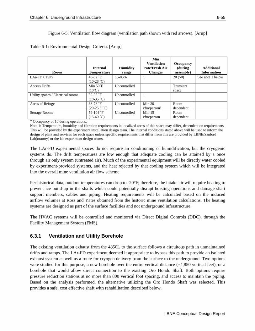
Chapter 6: Underground Infrastructure 6-55
LBNE Conceptual Design Report
Figure 6-5: Ventilation flow diagram (ventilation path shown with red arrows). [Arup]
Table 6-1: Environmental Design Criteria. [Arup]
Room Internal
Temperature Humidity
range
Min Ventilation
rate/Fresh Air Changes
Occupancy (during
assembly) Additional
Information LAr-FD Cavity 40-82 ˚F
(10-28 ˚C) 15-85% 1 20 (50) See note 1 below
Access Drifts Min 50˚F (10˚C)
Uncontrolled Transient space
Utility spaces / Electrical rooms 50-95 ˚F (10-35 ˚C)
Uncontrolled 1
Areas of Refuge 68-78 ˚F (20-25.6 ˚C)
Uncontrolled Min 20 cfm/person²
Room dependent
Storage Rooms 59-104 ˚F (15-40 ˚C)
Uncontrolled Min 15 cfm/person
Room dependent
* Occupancy of 10 during operations. Note 1: Temperature, humidity and filtration requirements in localized areas of this space may differ, dependent on requirements. This will be provided by the experiment installation design team. The internal conditions stated above will be used to inform the design of plant and services for each space unless specific requirements that differ from this are provided by LBNE/Sanford Lab[oratory] or the lab experiment design teams.
The LAr-FD experimental spaces do not require air conditioning or humidification, but the cryogenic systems do. The drift temperatures are low enough that adequate cooling can be attained by a once through air only system (untreated air). Much of the experimental equipment will be directly water cooled by experiment-provided systems, and the heat rejected by that cooling system which will be integrated into the overall mine ventilation air flow scheme.
Per historical data, outdoor temperatures can drop to -20°F; therefore, the intake air will require heating to prevent ice build-up in the shafts which could potentially disrupt hoisting operations and damage shaft support members, cables and piping. Heating requirements will be calculated based on the induced airflow volumes at Ross and Yates obtained from the historic mine ventilation calculations. The heating systems are designed as part of the surface facilities and not underground infrastructure.
The HVAC systems will be controlled and monitored via Direct Digital Controls (DDC), through the Facility Management System (FMS).
6.3.1 Ventilation and Utility Borehole
The existing ventilation exhaust from the 4850L to the surface follows a circuitous path in unmaintained drifts and ramps. The LAr-FD experiment deemed it appropriate to bypass this path to provide an isolated exhaust system as well as a route for cryogen delivery from the surface to the underground. Two options were studied for this purpose, a new borehole over the entire vertical distance (~4,850 vertical feet), or a borehole that would allow direct connection to the existing Oro Hondo Shaft. Both options require pressure reduction stations at no more than 800 vertical foot spacing, and access to maintain the piping. Based on the analysis performed, the alternative utilizing the Oro Hondo Shaft was selected. This provides a safe, cost effective shaft with rehabilitation described below.
6-56 Chapter 6: Underground Infrastructure
Volume 6: LBNE Conventional Facilities at the Far Site
The Oro Hondo Shaft has historically required removal of spalled rock on an annual to biannual basis, as it is an unsupported shaft. This is a reasonable solution for ventilation, though it does introduce risk over long life expectancies. For the LAr-FD experiment, the exhaust path also provides a cryogen delivery path. For this purpose, an unsupported shaft is not acceptable, and in fact routine access through the shaft is required. To provide a more permanent solution to the spalling rock problem, a rehabilitation design was presented by Arup during the DUSEL Preliminary Design development at 60% Preliminary Design. This rehabilitation design was not intended to provide permanent access, nor support for cryogen piping, so a combination of this design and a design for a new shaft connecting the 4850L to the 7400L were used to develop a cost estimate for an appropriate rehabilitation of the Oro Hondo Shaft.
As mentioned, the shaft must also support the installation of pressure reducing stations at 800-ft intervals. The levels selected for this design include the 800L, 1400L, 2000L, 2900L, 3650L, 4250L, and 4850L. While the distance from the 2000L to 2900L exceeds the requirement for a maximum spacing, an exception to the 800 ft spacing was made for this one location. These levels offer the best access through existing drifts to provide secondary egress. The pressure reducing stations themselves will be developed from the shaft, so the accesses do not require substantial modification.
Below the 3650L, a new 12-foot diameter borehole will be installed to provide a direct connection from the 4850L. Both this new borehole and the existing Oro Hondo Shaft will require permanent access. This is provided through the installation of a headframe and hoist building at the surface for the Oro Hondo Shaft, and an excavated sheave space and hoist room at the 3650L. In both cases, sufficient standby power is provided to allow the hoist to be lowered to the nearest level with a means of secondary egress. Standby power is not provided to allow these hoists to be used as an egress pathway. These shafts are intended solely for utility routing and maintenance of these utilities.
6.4 Electrical (WBS 130.06.05.05.03.04)
The underground facilities at the 4850L will have electrical power for normal operations as well as standby power for emergency occupant evacuation. LAr experiment power requires standby power for the cryostat heat, to prevent freezing of the surrounding rock and any water within it.
6.4.1 Normal Power
The electrical systems both at the surface and underground are designed to meet International Building Code (IBC) and applicable portions of the National Electric Code (NEC) and National Electric Safety Code (NESC). Underground portions also comply with National Fire Protection Association (NFPA) Code 520, which is specifically intended for underground facilities.
The estimated electrical loads for both the LAr-FD experiment and the underground infrastructure serving the experimental spaces are included in the facility load determination and design. These loads are shown in Table 3-1.
Power to serve the LAr-FD experiment will originate from the Ross substation and routed down the Ross Shaft to the 4850L. One 15kV mining cable shall be installed down the Ross Shaft to the 4850L and shall be cable rated for mine use, highly flame retardant, low smoke toxicity with high tensile strength and self-supporting. At the 4850L, the 15-kV mining cable will terminate in 15-kV switchgear located in a new
Chapter 6: Underground Infrastructure 6-57
LBNE Conceptual Design Report
Ross underground substation. Facility power will be provided in a similar manner, with a dedicated power supply through the Ross shaft terminating in the new electrical substation near the Ross Shaft. This will be provided early in the construction process to allow it to be used for construction.
Varying voltages will be distributed at strategic locations at the 4850L for use by LAr-FD and the facilities. To conserve space within the drifts, armored cable with low smoke properties will be used to distribute normal power wiring throughout the 4850L.
The LAr-FD experiment equipment will have a dedicated shielded transformer to serve the detector electronics at 208Y/120V. In addition, LAr-FD mechanical equipment will be fed from a dedicated transformer. Within the upper cavity, electrical panels and small transformers will serve equipment operating in the LAr-FD cavity. High voltage equipment and cables will be located away from the detector to meet the experiment Electromagnetic Interference (EMI) requirements.
6.4.2 Standby Power
Surface level generator sets, provided under the surface facilities and located near the Ross Shaft and Yates Shaft will be installed to provide standby power for life safety. Emergency lights, exit signs, 4850L AoRs, fire alarm, security, and IT System for communications will all be supplied by the standby power system.
There will be one multi conductor 15-kV mining armored cable, with low smoke properties, installed down the Ross Shaft from the surface level standby generation system to provide standby power at the 4850L. A redundant, 15-kV multiconductor armored mining cable will be installed down the Yates Shaft to the 4850L to provide a redundant path for standby power. The two 15-kV standby feeders will be tied together at the 4850L through sectionalizing switches.
6.4.3 Fire Alarm and Detection
The 4850L will have notification devices installed to alarm the occupants of a fire. Notification devices will consist of speakers and strobe lights. Manual pull stations will be provided within 200 ft of egress. Phones will be installed at the AORs, in the liquid argon chambers, and every 400 ft along the access drifts to communicate with the surface level command center.
An air sampling and gas detection system will be installed in the drifts and liquid argon detector chamber as an early detection of a fire condition. The air sampling system will be connected into the fire alarm system.
The fire alarm system will also interface with the Oxygen Depletion Hazard (ODH) system to activate the fire alarm system and initiate an alarm at the respective level fire alarm panel and at the surface level command center. Specific sounds and strobe colors will be identified based on the type of alarm (fire, ODH, etc.).
6-58 Chapter 6: Underground Infrastructure
Volume 6: LBNE Conventional Facilities at the Far Site
6.4.4 Lighting
Suspended lights mounted at a height just below the lowest obstruction will be provided for all drifts and ramps. Mounting is to be coordinated with conduit and supports of other systems running overhead. Maintained average illumination of approximately 24 lux (2.4 foot candles) at floor level will be provided throughout the drifts. Lighting control in drifts will be via low voltage occupancy sensors and power packs suitable for high humidity environments.
Lighting within equipment rooms will be UL Wet Location rated, watertight fluorescent fixtures. Exact layouts will be coordinated with final equipment at future design stages. Lighting control in equipment rooms will be via switch only, avoiding possibility of unexpected lights-off triggers.
All light fixtures within the liquid argon chamber will be UL Wet Location rated incandescent light fixtures to minimize Electromagnetic Interference (EMI) near the experiment. Average luminance levels at 0.7m above the liquid argon vessel roof will be between 100 and 150 lux (10-15 foot candles). All light fixtures will be controlled through a networked lighting control system allowing switching of multiple zones or circuits from multiple locations, and time schedule or other automated functions. Emergency light fixtures will be provided with 90 minute battery backup from a centralized system.
6.4.5 Grounding
The grounding system will be designed to provide effective grounding to enable protective devices to operate within a specified time during fault conditions, and to limit touch voltage under such conditions. The grounding system will be designed for a maximum resistance of 5 ohms where possible based on Mine Safety and Health Administration (MSHA) recommendations for ground resistance in mines. Ground beds, consisting of an array of ground rods, will be installed at each substation to provide low impedance to ground.
Main ground bars will be installed in the all substations. All extraneous conducting metal work will be bonded. A dedicated grounding cable will be distributed from the respective level substation ground bus to the LAr-FD detector chamber and from there to individual items of equipment and distribution boards.
A saturable inductor will be installed as part of the surface level work to mitigate common mode noise at the surface level transformers dedicated to the LAr-FD detector electronics. An Ufer grounding system will be provided by grounding the rebar within the liquid argon chambers to rock bolts which will be connected into the main 4850L grounding system. The Ufer grounding system will be connected to the main ground bus at the substation.
6.5 Plumbing (WBS 130.06.05.05.03.03)
Plumbing specific to the LAr-FD experiment includes plumbing for the cooling systems. Beyond this the facility requires supplies of both potable and industrial water, as well as a means to remove water inflows and sewage.
Chapter 6: Underground Infrastructure 6-59
LBNE Conceptual Design Report
6.5.1 Potable Water
An 8-inch potable water line will run down the Yates Shaft from the surface to the 4850L. It is not feasible to run an uninterrupted main water supply line from grade level down to serve the lower levels due to the extremely high hydrostatic pressure that would occur in the system. A series of pressure reducing stations will be located at regular intervals in intermediate levels in order to maintain the pressure within the capability of readily available piping. Each pressure reducing station will have two pressure reducing valve assemblies (PRVs), one duty, and one standby. On either end of each PRV, there will be a pressure transmitter which controls a motorized valve. Both the pressure transmitter and motorized valve will be tied to the Facility Management System (FMS). Pressure reducing stations will be located adjacent to the Yates shaft at the 800L, 1700L, 2600L, 3500L, 4100L, and 4850L.
A potable water double compartment storage tank will be located at 4100L in an existing drift. Water will be supplied to the tank from the potable water service downstream of the PRV at 4100L. Downstream of the PRV, the 8-inch potable water line will split to serve the domestic water tank and the fire water system for 4850L. The potable water storage tank will be 3,000 gallons that will satisfy 101 occupants in either the Yates or Ross AoRs. Potable water will be supplied to all AoRs, the LAr-FD cavity and all ancillary spaces requiring domestic water.
6.5.2 Industrial Water
A new 8-inch industrial water riser will be installed in the Ross Shaft from surface to the 4850L and will be used for construction and as a secondary fire service. It is not feasible to run an uninterrupted main water supply line from grade level down to serve the lower levels due to the extremely high hydrostatic pressure that would occur in the system. A series of pressure reducing stations will be located at regular intervals in intermediate levels and at the 4850L in order to maintain the pressure within the capability of readily available piping. The arrangement for the pressure reducing stations including the monitoring will be similar to the domestic water.
6.5.3 Fire Suppression
The source of fire water main will be the new 8-inch potable water main at the Yates Shaft and the new 8-inch industrial water riser at Ross Shaft. The connection to the potable water will be at 4100L and the connection to the industrial water riser will be at 4850L. The fire protection system at the 4850L Campus will be a gravity fed system. There will be a cross main throughout the west drift fed from both the Ross and the Yates Shafts. This main will consist of an 8-inch main within the campus serving all areas. There will be 2 main control valves for the 4850L fire water system, located in the drifts near the Yates and Ross Shafts at the 4850L Campus.
There will be multiple sprinkler zones in order to help determine the approximate location of a fire event. Sprinkler control valves will be located in the drifts, and will tap off the fire main running in the drifts.
Fire hose stations will be located along the drifts, LAr-FD, and ancillary spaces at a maximum distance of 200 ft apart. The standpipe system will be a wet pipe type with supply valve open and under water pressure at all times. There will be a double interlock pre-action system in the LAr-FD cavity activated by the smoke detectors to prevent any accidental sprinkler discharge over the sensitive equipment.
6-60 Chapter 6: Underground Infrastructure
Volume 6: LBNE Conventional Facilities at the Far Site
6.5.4 Drainage
Drainage from the drifts, mechanical electrical rooms (MER), and any areas where spillage is likely to occur will be collected locally in open sumps. Sumps will be located every 500 ft throughout the West drift, and in any areas where drainage to the drifts is not practical. Sumps will be equipped with sump pumps in a staged configuration where each pump discharging to the adjacent sump until water is discharged to the de-watering station near the Ross Shaft at 5000L.
6.5.5 Sanitary Drainage
Plumbing fixtures in the AoRs at Ross and Yates Shafts (4850L) will be drained by gravity pipes embedded in the floor slab piped to a vented sewage pit. This pit will be equipped with a manually operated sewage ejector. The sewage ejector will be emptied by the facility maintenance staff into a portable container after a signal from the ejector control panel to the Facility Management System indicates that the sump is full. The sump will be sized to hold all fixture discharges for 96 hours in addition to the normal fixture usage in the facility (i.e. beyond the point where a signal is sent to empty the sump).
An atmospheric vent to the surface is impractical. A 4-inch vent from the sewage ejector will terminate in the nearest appropriate drift. Plumbing fixtures in each AoR will be vented using air admittance valves.
All small AOR’s (10-20 occupants) will be equipped with chemical toilets and vented to the nearest drift.
6.5.6 Chilled Water
The LAr equipment will produce a significant amount of heat which will be removed by LBNE-provided chillers. Three chillers at 50% each have been selected to provide N+1 redundancy. Heat from the chillers and various process loads will be rejected using dry coolers located at the east end of the 4850L LAr-FD cavern adjacent to the chillers. To match the chiller arrangement and attain N+1 redundancy, a total of three dry coolers will be provided, each sized for 50% of the load. Air will be ducted directly to the dry coolers to avoid filtering it to the same degree as the air provided to the cavern. The dry coolers are typical AHU’s complete with a filter and a coil tailored to reject heat from the condenser water to the ventilation air. The ventilation air is a mixture of air (170,000 CFM) from the Yates and Ross Shafts at approximately 68°F. This volume of air is such that the total heat rejected (4320 MBH) will raise the air temperature to no more than 95°F. The dry coolers exhaust ductwork is arranged in a header and is ducted to the ventilation borehole.
Constant volume condenser water pumps are provided to also attain N+1 redundancy. The pumps shall be piped in a header arrangement to ensure maximum flexibility and redundancy in system. Each chiller and dry cooler shall have isolation valves to enable rotation. The FMS shall fully integrate with the chillers to enable/disable the condenser water system as necessary. A pressure transmitter shall monitor system pressure and shall annunciate a critical alarm to the FMS in the event of a low or high alarm. A chemical pot feeder is provided to ensure adequate water treatment in system.
A dedicated refrigerant relief vent line shall be provided from chillers to the drift downstream of exhaust fans near the exhaust ventilation borehole. In addition to this, the FMS shall monitor air quality in Chiller
Chapter 6: Underground Infrastructure 6-61
LBNE Conceptual Design Report
Room through the Refrigerant Leak Detection system. In the event of refrigerant leak detection, the chiller room exhaust motorized damper shall open (see damper matrix on design drawing) with a critical alarm annunciated to the FMS workstation. The chillers and its associated plant shall shutdown while the exit strobe lights and horns shall be activated. The system shall not restart until the refrigerant leak detector is re-set and the FMS operator has acknowledged and cleared the alarm event.
6.6 Cyberinfrastructure (WBS 130.06.05.05.03.01)
A fiber optic backbone provides communications for voice, data, and control of all systems on the surface and underground. Redundancy is built into the fiber-optic backbone by providing multiple cables to communication rooms at strategic locations throughout the site. Two separate backbone cables are routed between communication rooms (CR) along separate, diverse pathways to create a ring topology. Damage to the backbone at any point along the ring will not disrupt connectivity to the communication rooms. This design drastically improves the reliability and fault tolerance of the network systems.
Voice communications are provided via two-way radios and phones distributed throughout the underground spaces (in every room as well as every 500 ft in drifts). Two-way radios utilize a leaky feeder system to ensure communications over long distance without line of site. These leaky feeders are cables that act as antennas installed the length of all drifts and shafts. Phones utilize Voice over Internet Protocol (VoIP) to provide communication though the fiber optic data backbone.
The data system is designed to provide 10-Gigabit Ethernet in the backbone and 1-Gigabit Ethernet to connected systems (computers). This system is intentionally left at a lesser level of design due to the continuous progression and advancement of technology that will almost certainly result in more advanced technologies than are currently available being utilized at the time of construction.
A Command and Control Center at the surface will be the primary location for Human Machine Interface (HMI) with the control system for both the underground mechanical and electrical systems and the experiment. This room will also provide a central location for the asset and personnel tracking system (APTS) included in the design to provide personnel tracking for safety and asset tracking for security using Radio Frequency Identification (RFID) technology to sense when people or assets pass specified areas.
Along with the APTS system, an Asset Control and Alarm Monitoring System (ACAMS) provides security through programmable access control points and cameras to remotely control and monitor access to specified areas. This system could use key card technology similar to what is currently in use for security at the site or utilize similar RFID technology to that used for APTS.
The fire alarm and control system will be an isolated system from the remainder of the cyberinfrastructure to ensure reliability of this system independent of the control system.
6.7 Waste Rock Handling (WBS 130.06.05.05.03.07)
Prior to the commencement of any excavation activities, it will be necessary to complete the rehabilitation of the facility waste rock handling system. The capacity of this system will be equivalent to what was in place during mining. There are a number of components to the Facility waste rock handling system,
6-62 Chapter 6: Underground Infrastructure
Volume 6: LBNE Conventional Facilities at the Far Site
including refurbishing the Ross Shaft hoisting system, the Ross Shaft crushers, and the tramway; procuring track haulage equipment; and installing a surface conveyor to the Open Cut from the tramway dump.
The design presented here was developed for the DUSEL Project PDR by Arup/Tilley, is described in great detail the DUSEL Preliminary Design Report, Section 5.4.3.9 and is excerpted here. The systems utilize experience and equipment from the former Homestake Mining Company legacy, where rock was removed to the surface using skips in both the Yates and Ross Shafts. At the headframe of each shaft, the material was crushed to a nominal ¾ in, passed through ore bins, and was transported via underground rail to the mill system. The underground rail passed through a level called the tramway at approximately 125 ft (38 m) below the collar of the Yates Shaft. The third supply of ore was the Open Cut, where material was transported with haul trucks to a surface crushing system. A pipe conveyor (the longest in the world when it was constructed in 1987) delivered the material overland to the mill system.
During LBNE construction, the excavated waste rock material from the underground will be removed for disposal, with no intention of further processing. The Yates Shaft will primarily provide science access and will be rehabilitated during a significant portion of construction. The Ross Shaft will be the means of removing of material from the underground during construction.
The Ross skipping system allows material to be transported at a rate of 3,300 tons per 18-hour day, allowing six hours of downtime for maintenance, breaks, shift changes, etc. The loading pocket at the 5000L for the 4850L will be cleaned of any accumulated sand during the skip pocket rehabilitation prior to excavation starting. Several components of the rock removal system require rehabilitation, including the loading system, the skips, the scroll and the bin at the top of the headframe, the crushers, the electrical service equipment, the belt conveyors, and the dust collector. The gates at the base of the fine-ore bin at the tramway level (~125 ft [38 m] below the Ross Shaft collar will be replaced. The existing rail cars are not large enough to meet the cycle times required for construction, but the axles and wheels can be reused with new bodies. New locomotives will be purchased. At the point where the tramway exits the underground, the existing steel-sided building is in disrepair and will be replaced. All other equipment associated with this material handling system, including the original pipe conveyor, has been removed from the site.
The waste rock from the excavation will be relocated to the Open Cut via an overland conveyor, similar to one used during Homestake Mining Company operations, and the design team has been mindful of the impact this activity may have on the local community. The design will accommodate more stringent noise and dust requirements than other portions of the Project may require. In an effort to limit public exposure to this process, all material will be transported through residential areas only during a 10-hour daytime period, which requires a higher design capacity than a 24-hour operation would allow. A limit of 45 dBA at the property boundary has been established to further minimize the public impact. Extreme weather conditions experienced in Lead, South Dakota, must also be considered in the development of design requirements. The route of the waste rock handling system is shown in Figure 6-6.
The design excavation volume with allowances for rock support and shotcrete will be approximately 232,000 cubic yards (yd3) (177,000 cubic meters [m3]). Assuming an average of 10.5 in (0.27 m) of combined overbreak and lookout, with a 50% swell factor, the total volume of waste rock is expected to be approximately 368,000 yd3 (282,000 m3). This equates to approximately 606,000 short tons of
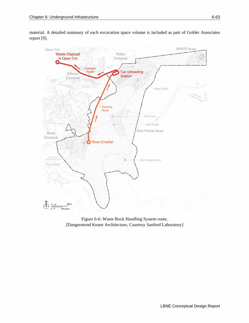
Chapter 6: Underground Infrastructure 6-63
LBNE Conceptual Design Report
material. A detailed summary of each excavation space volume is included as part of Golder Associates report [9].
Figure 6-6: Waste Rock Handling System route. [Dangermond Keane Architecture, Courtesy Sanford Laboratory]
64 References
Volume 6: LBNE Conventional Facilities at the Far Site
References
[1] "US Particle Physics: Scientific Opportunities, A Strategic Plan for the Next Ten Years, Report of
the Particle Physics Project Prioritization Panel," 29 May 2008.
[2] LBNE Science Collaboration, "LBNE Case Study Report: Liquid Argon TPC Far Detector v1.4," November 1, 2011.
[3] LBNE Collaboration, "The 2010 Interim Report of the Long-Baseline Neutrino Experiment Collaboration Physics Working Groups," FERMILAB-FN-0941-PPD,LBNE-PWG-004; arXiv:1110.6249 [hep-ex], 2011.
[4] Long-Baseline Neutrino Experiment Project, "Project Management Plan (LBNE-doc-2453)".
[5] Long-Baseline Neutrino Experiment Project, "Alternatives Analysis (LBNE-doc-4382)".
[6] Deep Underground Science and Engineering Laboratory, "Preliminary Design Report (LBNE-doc-2417-v2)," May 2011.
[7] T. J. Campbell, "Synopsis of Homestake Mine Geology," [Online]. Available: http://homestake.sdsmt.edu/Geology/geology.htm.
[8] Lachel Felice & Associates, "Geotechnical Engineering Services Final Report for 4850L Mapping (LBNE-doc-2417-v2)," September 2009.
[9] Golder Associates, "LBNE Far Site Detector Excavation Conceptual Design: 4850L Liquid Argon (LAr) Reference Design Final Report (LBNE-doc-4945)," November 4, 2011.
[10] Golder Associates, "In Situ Stress Measurement Deep Underground Science and Engineering Laboratory (LBNE-doc-2417-v2)," January 2010.
[11] A. Davis, C. J. Webb and F. Beaver, "Hydrology of the Proposed National Underground Science Laboratory at the Homestake Mine in Lead, South Dakota," Cincinnati, OH, 2003.
[12] HDR, "LAr 4850L Final Conceptual Design Report for LBNE Surface Facilities at Sanford Lab (LBNE-doc-4945)," November 4, 2011.
[13] LBNE, "LBNE LAr-FD Requirements Document (LBNE-doc-3747)".
[14] Golder Associates, "Conceptual Design Excavation Drawings (LBNE-doc-4945)," November 4, 2011.
[15] "Report on the Depth Requirements for a Massive Detector at Homestake (LBNE-doc-34)," 2008.
[16] Arup, USA, "LBNE at Sanford Lab: 100% Concept Design Report, Task 3a: LAr at 4850L (LBNE-doc-4945)," November 4, 2011.
[17] Arup, USA, "Conceptual Design Drawings (consolidated set) for LBNE LAr 4850L (LBNE-doc-4945)," November 11, 2011.
[18] Aon Risk Solutions, Fire Protection Engineering, "Fire Protection/Life Safety Assessment for the Conceptual Design of the Far Site of the Long Baseline Neutrino Experiement (LBNE-doc-4395)," October 11, 2011.
[19] G.L.Tiley, "Finite Element Analysis".