Embed Size (px)
Citation preview

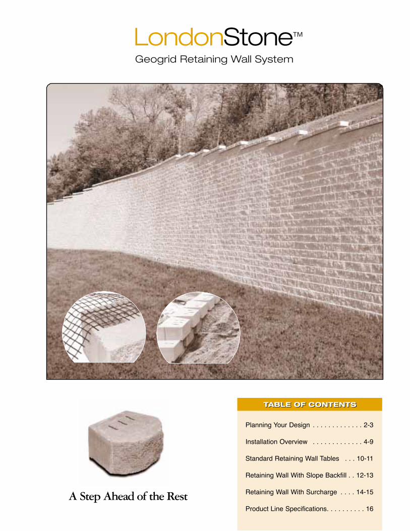
LondonStone™
Retaining wall systems
A Step Ahead of the Rest
LondonStone™
LondonLites™
Straight Face
LondonStone Steps
Rugged LondonStone
RETAINING WALL INSTALLATION GUIDERETAINING WALL INSTALLATION GUIDE

Rugged LondonStone
16
LondonStone™ Product Line SpecificationsLondonStone™ Product Line Specifications
7" Straight Face7 x 18 x 12
Weight: 80 lbs.Face Area: .88 sq. ftUnits per Cube: 27
4" Beveled Cap4 x 16 x 12
Weight: 50 lbs.Face Area: .44 sq. ftUnits per Cube: 45
Reversible Cap4 x 18 x 10 1/2
Weight: 45 lbs.Face Area: .50 sq. ftUnits per Cube: 60
Step Unit7 x 16 x 20
Weight: 168 lbs.Face Area: .78 sq. ftUnits per Cube: 12
Half Step7 x 8 x 20
Weight: 84 lbs.Face Area: .39 sq. ftUnits per Cube: 24
Decrowall4 x 12 x 8
Weight: 25 lbs.Face Area: .33 sq. ftUnits per Cube: 96
Decrowall Cap2 5/8" x 8 x 8
Weight: 10 lbs.Face Area: .14 sq. ftUnits per Cube: 208
7" LondonStone7 x 16 x 12
Weight: 75 lbs.Face Area: .78 sq. ftUnits per Cube: 27
12"
16"
7"
90º Corner
Split onback face
also
20"
16"
20"
8"
7"
12"
16"
4"
8"
12"
4"
12"
18"
7"
101/2 "
18"
4"
8"
8"
2 5/8 "
Rugged Cap4 x 18 x 10 1/2
Weight: 45 lbs.Face Area: .50 sq. ftUnits per Cube: 60
18" Rugged7 x 18 x 12
Weight: 79 lbs.Face Area: .88 sq. ft
12" Rugged7 x 12 x 12
Weight: 68 lbs.Face Area: .58 sq. ft
6" Rugged7 x 6 x 12
Weight: 35 lbs.Face Area: .29 sq. ft
7"
Rugged LondonStone is packaged as one unit in three different sizes. Rugged Cap is sold separately.
101/2 "
18"
4"
12"
18"
7"
12"
6"
Split onback face
also
Patent Pending London Lites™ Patented
The only lite system...
• An affordable landscape lighting alternative
• Low voltage lighting system designed into all of our block sizes & colors
• Easy installation
• Safety feature of having a wall lit stairway or walkway
• Easy maintenancewith a screw inlens cap on thefront of the block
A Step Ahead of the Rest
LondonStone™
TABLE OF CONTENTSTABLE OF CONTENTS
Planning Your Design . . . . . . . . . . . . . 2-3
Installation Overview . . . . . . . . . . . . . 4-9
Standard Retaining Wall Tables . . . 10-11
Retaining Wall With Slope Backfill . . 12-13
Retaining Wall With Surcharge . . . . 14-15
Product Line Specifications. . . . . . . . . . 16
Geogrid Retaining Wall System

14
LondonStone™ Retaining Wall with SurchargeLondonStone™ Retaining Wall with Surcharge
RETAINING WALL WITH A LOADSurcharge loads on a retaining wall may be caused by avariety of sources, e.g., parking lots, bulk storage, buildings,and other retaining walls.
In general, if the source of surcharge is at least a distancetwice the total height of the surcharged wall, its influence isminimal and may be safelyignored in your design.
Methodology: NCMA Design Manual for SRW, 2nd edition. Grid reinforcement LTDS = 1250 lbs/ft. γ = 120 pcf, Sliding SF = 1.5 Overturning SF = 2.0, Global stability checks not included, Soils compacted to min. 95% proctor, No additional surcharges on wall. No water loading. Level wall toe only.
e.g.
San
d / G
rave
le.
g. S
ilty
San
de.
g. S
andy
Silt
/ Le
an C
lay
LONDONSTONE GRID LIP BLOCK: NO SLOPE WITH 250 PSF SURCHARGE
TOTALWALL
HEIGHTH
EXPOSEDWALL
HEIGHTH1
EMBEDMENTD
NUMBEROF
COURSES
GEOGRIDTYPE
GEOGRIDLENGTH
L
NUMBEROF
GEOGRIDLAYERS
(ft) (ft) (ft) --- --- (ft) GRID ELEVATION FROM FIRST COURSE BOTTOM ---4'-8" 4'-2" 0'-6" 8 5XT 5'-0" 1'-9" 3'-6" 2
5'-10" 5'-4" 0'-6" 10 5XT 5'-0" 1'-2" 2'-11" 4'-8" 37'-0" 6'-6" 0'-6" 12 5XT 6'-6" 1'-2" 2'-11" 4'-8" 6'-5" 48'-9" 7'-9" 1'- 0" 15 5XT 7'-0" 1'-9" 3'-6" 5'-10" 7'-0" 4
10'-6" 9'-6" 1'- 0" 18 5XT 8'-0" 0'-7" 2'-4" 4'-1" 5'-10" 7'-7" 9'-4" 6
φ =
34°
11'-8" 10'-8" 1'- 0" 20 5XT 8'-6" 0'-7" 2'-4" 4'-1" 5'-10" 7'-7" 9'-4" 7
TOTALWALL
HEIGHTH
EXPOSEDWALL
HEIGHTH1
EMBEDMENTD
NUMBEROF
COURSES
GEOGRIDTYPE
GEOGRIDLENGTH
L
NUMBEROF
GEOGRIDLAYERS
(ft) (ft) (ft) --- --- (ft) GRID ELEVATION FROM FIRST COURSE BOTTOM ---4'-8" 4'-2" 0'-6" 8 5XT 6'-0" 1'-9" 3'-6" 2
5'-10" 5'-4" 0'-6" 10 5XT 6'-6" 1'-9" 3'-6" 4'-8" 37'-0" 7'-1" 0'-6" 13 5XT 6'-6" 1'-2" 2'-4" 4'-8" 5'-10" 48'-9" 7'-9" 1'-0" 15 5XT 7'-6" 0'-7" 1'-9" 3'-6" 5'-3" 7'-0" 5
10'-6" 9'-6" 1'-0" 18 5XT 8'-6" 0'-7" 1'-9" 3'-6" 5'-3" 7'-0" 8'-9" 6
φ =
30°
11'-8" 10'-8" 1'-0" 20 5XT 10'-0" 0'-7" 1'-9" 3'-6" 5'-3" 7'-0" 8'-9" 10'-6" 7
TOTALWALL
HEIGHTH
EXPOSEDWALL
HEIGHTH1
EMBEDMENTD
NUMBEROF
COURSES
GEOGRIDTYPE
GEOGRIDLENGTH
L
NUMBEROF
GEOGRIDLAYERS
(ft) (ft) (ft) --- --- (ft) GRID ELEVATION FROM FIRST COURSE BOTTOM ---4'-8" 4'-2" 0'-6" 8 5XT 7'-6" 1'-9" 3'-6" 2
5'-10" 5'-4" 0'-6" 10 5XT 8'-6" 1'-2" 2'-11" 4'-8" 37'-0" 6'-6" 0'-6" 12 5XT 7'-6" 1'-2" 2'-11" 4'-8" 5'-10" 48'-9" 7'-9" 1'-0" 15 5XT 8'-6" 1'-2" 2'-11" 4'-8" 6'-5" 7'-7" 5
10'-6" 9'-6" 1'-0" 18 5XT 11'-0" 0'-7" 2'-4" 4'-1" 5'-10" 7'-7" 9'-4" 6
φ =
28°
11'-8" 10'-8" 1'-0" 20 5XT 10'-0" 0'-7" 2'-4" 4'-1" 5'-10" 7'-7" 9'-4" 10'-6" 7
10'-6"

3
OTHER STRUCTURESNEARBYLoads due to structures such asbuildings, parking lots, storageareas, etc. close to your wall canhave an impact on final design.Depending on the circumstances,these loads may be classified eitheras live or dead, depending on theirrelative duration.
For example, slopes generally areconsidered dead loads, whereasloads coming from parking lots maybe classified as live, due to theirshorter duration. Dead loads, e.g.,building loads, or loads from a tieredwall may contribute to the overallstability of the wall, depending oncloseness to the wall edge. As ageneral rule, the closer to the walledge the more likely it is that thoseloads may stabilize the wall,however, surcharges increase thestresses on both block andreinforcing grids. Keep in mindthese facts will contribute to abalanced design.
Live loads, such as those resultingfrom bulk storage, vehicular traffic,etc. may act both as stabilizing anddestabilizing forces in your design.Typically, a conservative designapproach is to neglect any live loadsas part of the resisting set of forcesin design.
As a rule of thumb, surcharge loadsthat are at a distance of twice theheight of a wall below can beneglected in a design.
SOILSSoils are important not only becausethey will ultimately bear the weightof the wall structure you design, butalso because their propertiesdirectly affect your design.
For example, typically well-gradedcoarse sands have better designproperties than finer soils, like clay.Particles in these sands fill voidsand interlock better than uniformgranular soils or clays, resulting instronger structures. Soils that areexpansive, or organic (peats, etc.)should be avoided as fill materialwhen building walls.
Also, granular soils that are toocoarse or sharp should be avoidedas fill material, since they maydamage the reinforcing grid. If thesite has unsuitable soils (disturbedsoils, soft, expansive, chemicallyaggressive, etc.) they must beexcavated and replaced withappropriate materials prior to anyother work, before the wall iserected.
WATEROne crucial site characteristic thatmust be checked before any designis carried out is the presence ofgroundwater. The presence of awater table too close to the bottomof the foundation pad (less than 2/3the height of the wall), or suspicionof a seasonally shifting water tablecan dramatically reduce the integrityof your wall if left unchecked.
Also, be sure to check for thepresence of waterways, or movingfloodwaters that could cause scourof the foundation at the top of thewall. In addition, you must makesure that terrain features do notbring surface water near your wall. Ifthat is the case, your design shouldinclude details to ensure water getsdiverted from your structure. Theseinclude swales over and around thetop of the wall, slopes, impervioussoil tightly compacted at keylocations, etc. These provisionsshould not be confused with internaldrainage within the wall structure,typically comprised of granularaggregate drainage directly behindthe wall face, drain tile pipes, andchimney drains behind thereinforced soil mass.

12
LondonStone™ Wall with Sloped BackfillLondonStone™ Wall with Sloped Backfill
RETAINING WALL ON A SLOPEThe grid quantities in these tables should cover walls withback slopes up to and including 2.5:1. For more complex,steeper slopes contact your LondonStone representative.
When high runoff is anticipated, your design may call for atop drain swale or other means of diverting water before itenters the wall mass.
A licensed engineer should review your wall design if the toeis sloped or it has a body of water near it, such as detentionponds, etc.
e.g.
San
d / G
rave
le.
g. S
ilty
San
de.
g. S
andy
Silt
/ Le
an C
lay
LONDONSTONE GRID LIP BLOCK: 1:2_ SLOPE
TOTALWALL
HEIGHTH
EXPOSEDWALL
HEIGHTH1
EMBEDMENTD
NUMBEROF
COURSES
GEOGRIDTYPE
GEOGRIDLENGTH
L
NUMBEROF
GEOGRIDLAYERS
(ft) (ft) (ft) --- --- (ft) GRID ELEVATION FROM FIRST COURSE BOTTOM ---4'-8" 4'-2" 0'-6" 8 5XT 4'-0" 1'-2" 2'-11" 25'-10" 5'-4" 0'-6" 10 5XT 4'-6" 0'-7" 1'-9" 3'-6" 37'-0" 6'-6" 0'-6" 12 5XT 6'-0" 1'-9" 3'-6" 5'-3" 38'-9" 7'-9" 1'- 0" 15 5XT 7'-0" 1'-9" 3'-6" 5'-3" 7'-0" 410'-6" 9'-6" 1'- 0" 18 5XT 8'-6" 0'-7" 1'-9" 3'-6" 5'-3" 7'-0" 8'-9" 6
φ =
34°
11'-8" 10'-8" 1'- 0" 20 5XT 9'-0" 1'-2" 1'-9" 4'-8" 6'-5" 8'-2" 9'-11" 6
TOTALWALL
HEIGHTH
EXPOSEDWALL
HEIGHTH1
EMBEDMENTD
NUMBEROF
COURSES
GEOGRIDTYPE
GEOGRIDLENGTH
L
NUMBEROF
GEOGRIDLAYERS
(ft) (ft) (ft) --- --- (ft) GRID ELEVATION FROM FIRST COURSE BOTTOM ---4'-8" 4'-2" 0'-6" 8 5XT 4'-6" 1'-2" 2'-11" 2
5'-10" 5'-4" 0'-6" 10 5XT 5'-6" 0'-7" 2'-4" 4'-1" 37'-0" 7'-1" 0'-6" 13 5XT 7'-0" 0'-7" 1'-9" 3'-6" 5'-3" 48'-9" 7'-9" 1'-0" 15 5XT 8'-0" 0'-7" 1'-9" 3'-6" 5'-3" 7'-0" 5
10'-6" 9'-6" 1'-0" 18 5XT 9'-6" 0'-7" 1'-9" 3'-6" 5'-3" 7'-0" 8'-9" 6
φ =
30°
11'-8" 10'-8" 1'-0" 20 5XT 9'-0" 1'-2" 1'-9" 2'-11" 4'-8" 6'-5" 8'-2" 9'-11" 7
TOTALWALL
HEIGHTH
EXPOSEDWALL
HEIGHTH1
EMBEDMENTD
NUMBEROF
COURSES
GEOGRIDTYPE
GEOGRIDLENGTH
L
NUMBEROF
GEOGRIDLAYERS
(ft) (ft) (ft) --- --- (ft) GRID ELEVATION FROM FIRST COURSE BOTTOM ---4'-8" 4'-2" 0'-6" 8 5XT 5'-0" 1'-2" 2'-11" 2
5'-10" 5'-4" 0'-6" 10 5XT 6'-0" 0'-7" 2'-4" 4'-1" 37'-0" 6'-6" 0'-6" 12 5XT 8'-0" 0'-7" 2'-4" 4'-1" 5'-10" 48'-9" 7'-9" 1'-0" 15 5XT 9'-6" 1'-2" 2'-4" 3'-6" 5'-3" 7'-0" 5
10'-6" 9'-6" 1'-0" 18 5XT 9'-9" 0'-7" 1'-9" 3'-6" 5'-3" 7'-0" 5
φ =
28°
11'-8" 10'-8" 1'-0" 20 5XT 13'-0" 0'-7" 1'-9" 3'-6" 5'-3" 7'-0" 8'-9" 6
Methodology: NCMA Design Manual for SRW, 2nd edition. Grid reinforcement LTDS = 1250 lbs/ft. γ = 120 pcf, Sliding SF = 1.5 Overturning SF = 2.0, Global stability checks not included, Soils compacted to min. 95% proctor, No additional surcharges on wall. No water loading. Level wall toe only.

5
EXCAVATION/BASE PREPARATION
1. Foundation soil shall be examined toensure that it is adequate forsupporting the proposed retainingwall structure.
2. Foundation soil shall be excavated asrequired for base course levelingdimension as shown on theconstruction drawings.
3. Base materials should be to the depth and widths shownin the construction drawings with a minimum width of24" and depth of 6". Embedment of the units isrecommended and should coincide with the engineerspecifications.
4. Granular inorganic material should be used for basematerial (i.e. class 5, recycled concrete…)
5. Compact with a mechanical platecompactor to 95% standard proctor.
6. Level compacted base material fromside to side and front to back.
7. A drainage pipe should be installedon walls exceeding 4 feet. Thedrainage collection pipe shoulddaylight into a storm sewer manhole or to a sloped arealower than the pipes behind the walls. The main collectiondrainpipe just behind the block facing shall be a minimumof 3" in diameter.
LONDONSTONE
COURSES
WALLHEIGHT
WALL SETBACK
ft-in in
4 2'- 4" 3.13
5 2'-11" 4.52
6 3'-6" 5.65
7 4'-1" 6.78
8 4'-8" 7.91
9 5'-3" 9.04
10 5'-10" 10.17
11 6'-5" 11.30
12 7'-0" 12.43
13 7'-7" 13.56
14 8'-2" 14.69
15 8'-9" 15.82
16 9'-4" 16.95
17 9'-11" 18.08
18 10'-6" 19.21
19 11'-1" 20.34
20
Situation Embedment
11'-8"
Level slope toe H' / 20
Level slope (abutments) H' / 10
3H : 1V slope toe H' / 10
2H : 1V slope toe H' / 7
* H' = exposed wall height
21.47
CONSTRUCTION PLANNING
One important aspect of your planning is accounting forthe setback each successive course will have basedupon the batter of your LondonStone wall. The battermakes your wall lean back at an angle of 6.11° from thevertical, or ≤” for every 7” of vertical wall unit. If thissetback is not considered, your desired layout may beimpossible to realize once the minimum radius ofcurvature of the LondonStone block has been reached.
This is especially important for tall walls with tightcurves, but it should be considered for every wall youdesign. The following table should help you calculate thesetback for each additional LondonStone course you layout in your project.

10
LondonStone™ Standard Retaining WallLondonStone™ Standard Retaining Wall
Methodology: NCMA Design Manual for SRW, 2nd edition. Grid reinforcement LTDS = 1250 lbs/ft. γ = 120 pcf, Sliding SF = 1.5 Overturning SF = 2.0, Global stability checks not included, Soils compacted to min. 95% proctor, No additional surcharges on wall. No water loading. Level wall toe only.
TOTALWALL
HEIGHTH
EXPOSEDWALL
HEIGHTH1
EMBEDMENTD
NUMBEROF
COURSES
GEOGRIDTYPE
GEOGRIDLENGTH
L
NUMBEROF
GEOGRIDLAYERS
(ft) (ft) (ft) --- --- (ft) GRID ELEVATION FROM FIRST COURSE BOTTOM ---4'-8" 4'-2" 0'-6" 8 5XT 3'-6" 2'-4" 1
5'-10" 5'-4" 0'-6" 10 5XT 4'-0" 1'-2" 3'-6" 27'-0" 6'-6" 0'-6" 12 5XT 5'-0" 1'-9" 3'-6" 5'-3" 38'-9" 7'-9" 1'- 0" 15 5XT 6'-0" 1'-9" 3'-6" 5'-3" 7'-0" 4
10'-6" 9'-6" 1'- 0" 18 5XT 7'-0" 1'-9" 3'-6" 5'-3" 7'-0" 8'-9" 5
φ =
34°
e.g.
San
d / G
rave
le.
g. S
ilty
San
de.
g. S
andy
Silt
/ Le
an C
lay
11'-8" 10'-8" 1'- 0" 20 5XT 7'-6" 1'-2" 2'-11" 4'-8" 6'-5" 8'-2" 9'-11" 6
TOTALWALL
HEIGHTH
EXPOSEDWALL
HEIGHTH1
EMBEDMENTD
NUMBEROF
COURSES
GEOGRIDTYPE
GEOGRIDLENGTH
L
NUMBEROF
GEOGRIDLAYERS
(ft) (ft) (ft) --- --- (ft) GRID ELEVATION FROM FIRST COURSE BOTTOM ---4'-8" 4'-2" 0'-6" 8 5XT 4'-6" 2'-4" 1
5'-10" 5'-4" 0'-6" 10 5XT 4'-6" 0'-7" 2'-4" 4'-1" 37'-0" 7'-1" 0'-6" 13 5XT 5'-6" 1'-9" 3'-6" 5'-3" 38'-9" 7'-9" 1'-0" 15 5XT 6'-6" 1'-9" 3'-6" 5'-3" 7'-0" 4
10'-6" 9'-6" 1'-0" 18 5XT 7'-6" 1'-9" 3'-6" 5'-3" 7'-0" 8'-9" 5
φ =
30°
11'-8" 10'-8" 1'-0" 20 5XT 8'-6" 1'-2" 2'-11" 4'-8" 6'-5" 8'-2" 9'-11" 6
TOTALWALL
HEIGHTH
EXPOSEDWALL
HEIGHTH1
EMBEDMENTD
NUMBEROF
COURSES
GEOGRIDTYPE
GEOGRIDLENGTH
L
NUMBEROF
GEOGRIDLAYERS
(ft) (ft) (ft) --- --- (ft) GRID ELEVATION FROM FIRST COURSE BOTTOM ---4'-8" 4'-2" 0'-6" 8 5XT 4'-6" 2'-4" 1
5'-10" 5'-4" 0'-6" 10 5XT 5'-0" 0'-7" 2'-4" 4'-1" 37'-0" 6'-6" 0'-6" 12 5XT 5'-6" 0'-7" 2'-11" 5'-3" 38'-9" 7'-9" 1'-0" 15 5XT 6'-6" 1'-9" 3'-6" 5'-3" 7'-0" 4
10'-6" 9'-6" 1'-0" 18 5XT 8'-0" 1'-9" 3'-6" 5'-3" 7'-0" 8'-9" 5
φ =
28°
11'-8" 10'-8" 1'-0" 20 5XT 8'-6" 1'-2" 2'-11" 4'-8" 6'-5" 8'-2" 9'-11" 6
LONDONSTONE GRID LIP BLOCK: NO SLOPE NO SURCHARGE
THE STANDARD RETAINING WALLThe basic retaining wall design consists of a straight wallsegment with no slope or surcharge load behind it.
The tables on this page and the following pages for otherloading conditions feature approximate quantities ofreinforcing grid. Use these tables for estimating purposes only.
Quantities, positioning and lengths may vary. Curves, anglesand other features may also have an impact on the finalamounts of grid and LondonStone Grid Lip block needed.Contact your LondonStone representative for actual gridlayout and sizing at the early stage of your planning.
These tables were prepared for the reinforcing grid type andspecifications of the wall heights indicated. Other designsmay be possible.
For taller walls, or walls under loading conditions or terraindifferent than those illustrated in this manual, a qualifieddesign professional should be consulted.
All final designs should be reviewed and approved by a qualified licensed engineer (P.E.) prior to construction.

INSTALLING SUCCESSIVE COURSES OFSRW UNITS
1. Ensure the drainage aggregate islevel with, or slightly below the topof the SRW unit.
2. Clean debris off of top of unit.
3. Stack the next row of block so theseams are offset from the blocksbelow. (A running bond pattern onthe face of the wall is preferred butnot required.)
4. Place and move LondonStone units to engage shearconnector/lip and establish proper setback.
5. Sight down the wall line to ensure wall straightness.Adjust units as needed to form straight lines and smooth curves.
6. Place drainage aggregate and infill soil as statedpreviously.
STEPS
1. Most municipal building departments have coderequirements for steps used in site construction. Checkwith local building officials for requirements.
2. Specify width of stairway. Various incremental dimensionsare possible with unit modification. Each LondonStonestep unit is 16" wide. Therefore, widths of 16", 32", 48",64",… are possible without step-unit modification.
3. Calculate height and depth of stairway. The LondonStonestep offers flexibility because tread lengths between 8"and 16" are attainable. Ex.: 12 step units (risers) x 7" =84" (total height of stairway). With tread lengths of 16",total distance steps will travel = 196". With tread lengthsof 12", total distance steps will travel = 152".
4. If steps are being built adjoining aLondonStone wall, use the samegrade lines as used for the wall. Ifnot, embed the step unit far enoughto allow the next course of steps toalign with the base course of wall.
5. Use the same base and backfillmaterial as recommended forLondonStone units. (Base material= granular inorganic material compacted to 95%standard proctor) (Backfill material should be drainagematerial 3/4 rock)
7
Cut Units 2" To Allow Pipe ThroughDaylight Drain
every 40 ft. max
Typical Daylight Through Wall Face Construction Detail
Figure B

8
USING THE GEOGRID SYSTEM
1. Install units up to the designated height of the first gridlayer, making sure to backfill and compact behind thewall to a depth equal to the designed grid length.
2. Cut grid to design length as shown on the plans and install with design strength directionperpendicular to the wall face. Seams or overlaps of gridparallel to the wall face are not permitted.
3. Place next course of block on top of grid in a manner thatforces LondonStone GridLip into grid squares.
4. Place a 8" layer of backfill soil on top of the grid andcompact to a minimum 95% standard proctor density.
5. Only hand-operated equipment should be allowed within3 feet of the wall. Track construction equipment shall notbe operated on less than 6" of compacted infill material.
GEOGRID GRID LAYOUT IN CURVES AND CORNERS
Curves and corners in designs need additionalconsiderations for the correct layout of the reinforcing grid.Interior corners will invariably force you to leave gapsbetween grid sheets, due to the curvature. To close thesegaps, you should install additional reinforcement on placeswhere gaps occur and on the next course above prior tobackfilling [See Figure A].
In addition, square corners require that the 90° gap be filledwith an extension of the reinforcing sheet equal to 25% ofthe total wall height, on alternate sides of the gap as you goup. [See Figure B]
In contrast, exterior corners will always cause reinforcinggrids to overlap, which in turn dramatically reduces the loadcarrying capacity of the grid. To correct this, a minimum of3" fill must be placed between sheets at those overlap areasprior to backfilling that lift, as shown in Figure C & D.
Scale: NTS
Inside Curve Grid Layout (TYP)
Standard System Installation OverviewStandard System Installation Overview
Figure A

9
q y ( )
Alternate Extension of reinforcement H/4 length on subsequent specified - reinforcement elevations
Main direction of reinforcement strength
Main direction of reinforcement
strength
H/4 From Back Of Block
H/4 From Back Of Block
Inside Square Corner Reinforcement Layout (TYP)
Scale: NTS
STEP #1: Place grid so as to minimize overlap. Place 3" fill between any overlapping edges
STEP #2: Install the next block course. Mark those blocks where there were gaps left in the grid below . Backfill and compact.
STEP #3: Place grid over the areas where gaps were left. Backfill and compact. If overlapping, fill as in Step #1.
Outside Curve Grid Layout (TYP)
Main direction of reinforcement
strength
Main direction of reinforcement strength
Scale: NTS
Scale: NTS
Required Length
Min. 3" of fill required between grid layers at overlap area when placed at same elevation. Alternative: Shift up or down one of the grid layers from the specified elevation. Maintain specified strength direction at all times.
RequiredLength
Outside Square Corner Reinforcement Layout (TYP)
CAPPING1. Install 4" LondonStone Reversible Cap, 4"
LondonStone Beveled Cap or 7" Round Cap(optional).
2. Make sure that the surfaces of the cap unitand unit the cap is being placed on are dryand free of debris.
3. Apply construction adhesive on cap unitand place on top course of wall.
4. The cap may be placed flush with the faceof the wall, set back slightly or overhangingas much as one inch depending onaesthetics and design.
Figure B
Figure C
Figure D

6
SETTING THE FIRST COURSE
1. Begin at the lowest elevation of the wall.
2. The first course of LondonStoneunits shall be placed on the levelingpad and checked for level andalignment.
3. Installer should ensure that theunits are in full contact with thebase. Units are placed side by side for the full length of thewall.
4. Using a rubber mallet and a smallamount of coarse sand, modifywhere necessary to ensure astraight and level base course.
5. Alignment may be done by meansof a string line or offset from thebase line.
6. Please note: The completed wallerection shall be within plus/minus 1.25" measured overa 10' distance in either a horizontal or vertical directioncompared to the design line and grade control.
BACKFILL
1. All drainage material in thedrainfield and infill soils within 3 feetof the wall must be properlycompacted using a plate compactoror manual plate tamper.
2. Compact in maximum 7" lifts – i.e.compaction should occur with eachcourse of LondonStone units set.
3. Place drainage aggregate behind and up to the height ofthe LondonStone wall.
4. Drainage aggregate shall be placed to a minimumthickness of 12" measured from the back of theLondonStone unit.
5. If required, install geotextile filterfabric between the compactedbackfill material and compactedinfill soil.
6. If using geogrid reinforcement, besure to avoid using compactingequipment directly on geogrid. Placethe next 7" lift of soil on top of thegrid before compacting.
Scale: NTS
Native Undisturbed Soil (TYP)
Extend MinimumTwo Blocks Into Slope
Finished Grade
Min. 6"CompactedGranular
Typical Stepping-Up Grid Lip Construction Detail
Standard System Installation OverviewStandard System Installation Overview
Figure A
Recommended Construction Tolerances
Vertical ± 1.25" / 10 ft
Horizontal Straight lines: ± 1.25" / 10 ft
Rotation From design wall batter: 2º
Bulging 1.00" / 10 ft
3" maximum
3" maximum

11
Compacted Impervious Soil
Reinforcing gridlayout & lengthper specifications
Compacted Impervious Soil
Drainage Fill 12" minimum
Drainage Fill 12" minimum
Drain pipe elevation variesOutlet at wall end or every 40' maximum
Leveling pad 6" thick minimum
Leveling pad 6" thick minimum
Embedment Depth D
TypicalExcavationLine
L
ExposedWall
HeightH1
ExposedWall
HeightH1
TotalWall
HeightH
TotalWall
HeightH
L
Drain pipe elevation variesOutlet at wall end or every 40' maximum
Standard Wall Construction DetailsStandard Wall Construction Details

4
UNREINFORCED WALLSA retaining wall is a structure that resists the forcesfrom a soil mass by virtue of its own weight. Inmany cases, a simple gravity wall (with no geogridreinforcement required) will be all that is needed toretain a soil mass. The soil is kept in place by thesole weight of the stacked concrete blocks. Wherethis weight alone is not enough, the use ofreinforcement grid brings together a larger mass ofsoil to counteract the pressures of the retained soil.
Generally, if the terrain is level, with appropriatesoil, no surcharges, or water masses nearby,unreinforced walls can be built up to a height of 3.5to 4 ft, depending on soil and terrain conditions.Otherwise, a complete review by a qualifiedlicensed professional (P.E.) is strongly encouraged.
REINFORCED WALLSWhen your wall design calls for taller walls, orunder special conditions, such as tiers, slopes, orsurcharges behind the wall, reinforcing grid may berequired to stabilize the wall. Grid layers work bybringing together a larger mass to aid the wall inresisting the forces exerted by the retained soil.
LondonStone retaining walls areenvironmentally friendly and complimentany environment. It’s the perfectsolution for any residential orcommercial landscape project.
Standard System Installation OverviewStandard System Installation Overview
KEY POINTS TO CONSIDER BEFORE BEGINNING THE PROJECT
• Stepping up along a grade should be accomplished byembedding at least two LondonStone block units underthe grade line, to ensure the full capacities of the blockare available to the wall. (Page 6, Figure A)
• Drain pipe in your LondonStone Wall should haveoutlets, “daylight drains” or “weep holes” maximumevery 40 ft. Your LondonStone units should be cut asindicated in the figure to ensure a quality finish.(Page 7, Figure B)
• Erosion at the top ends of the wall can be reduced by“curling” your wall top courses into the slope or bank asyou progress toward the ends. However, in taller wallsthis may also increase the stress on the lower portionsof the wall and may require additional support under thecurled portion of the wall.
• In high runoff areas, you should consider finishing thetop layer of backfill with a 6” layer of impervious soil, toprevent the runoff from saturating the filled portion of thesoil behind the wall.
• In walls with a sloped backfill, large paved areas, orother conditions that may concentrate high runoff water,you may also consider the use of a drain swale, to helpcarry the runoff away from the wall. Consult your JMErepresentative for more information.
• Finally, your design should include planning for utilitiesrunning through the wall or into the backfilled portion of it.

Reinforcing gridlayout & lengthper specifications
Compacted Impervious Soil
Drainage Fill 12" minimum
Drainage Fill 12" minimum
Drain pipe elevation variesOutlet at wall end or every 40' maximum
Drain pipe elevation variesOutlet at wall end or every 40' maximum
Leveling pad 6" thick minimum
Leveling pad 6" thick minimum
Embedment Depth D
Compacted impervious soil12" deep recomended
ExposedWall
HeightH1
ExposedWall
HeightH1
TotalWall
HeightH
TotalWall
HeightH
L
TypicalExcavationLine
L
13
Sloped Backfill Wall Construction DetailsSloped Backfill Wall Construction Details

2
TERRAIN GEOMETRYThe first consideration when startinga wall design is to look at the sitetopography. Careful examination ofchanges in terrain elevation will helpreduce excavation costs and plan foradequate drainage and otherremedies to channel water awayfrom your wall.
Other important aspects to considerat this stage are whether adjacentconstruction, waterways or otherterrain features could have an effecton the design or performance of yourwall over time.
GRADINGA careful examination of terraingrading both above and below theplanned wall is essential. Slopesabove the wall create overloads onthe wall, whereas a sloping grade atthe wall footing typically decreasesthe available resistance to thedesign loads.
Grading can also create problems and challenge the good long-termperformance of your wall if it channelsor retains water on or near it.
Planning Your DesignPlanning Your Design
Designing a wall involves more than just calculatingthe number of courses and amount of grid it will taketo cover a desired length.
When bringing your project from idea to reality, careful planning at theearly stages goes a long way toward minimizing costs, repairs and otherproject setbacks. Proper consideration of construction site features,obstacles and constraints is also essential for a cost-effective design, asall of these will influence your final product.

15
Compacted Impervious Soil
Reinforcing gridlayout & lengthper specifications
Compacted Impervious Soil
Drainage Fill 12" minimum
Drainage Fill 12" minimum
Drain pipe elevation variesOutlet at wall end or every 40' maximum
Leveling pad 6" thick minimum
Leveling pad 6" thick minimum
Embedment Depth D
ExposedWall
HeightH1
ExposedWall
HeightH1
TotalWall
HeightH
TotalWall
HeightH
L
TypicalExcavationLine
L
Drain pipe elevation variesOutlet at wall end or every 40' maximum
Surcharge Wall Construction DetailsSurcharge Wall Construction Details

LondonStone has been manufacturing superior
quality concrete products for over 10 years.
By combining the highest quality material and
superior customer service we have become a
leader in the concrete manufacturing industry.
When you’re in need of quality products with
superior service, give us a call. It would be our
pleasure to help you find the best solution.Lon
do
nS
ton
e™
Re
tain
ing
wa
llsy
ste
ms

DISCLAIMER:
The suggested design materials presented in this manual are for
estimating tasks and reference only. It is the user’s responsibility
to ensure that a final, project-specific design is reviewed, approved
and sealed by a registered Professional Engineer, based on actual
soil conditions. It is the project owner’s responsibility to ensure the
adequacy of the designed segmental retaining wall incorporated
into the overall project through a specification. The specification
should include factors which affect the overall integrity of the
retaining wall such as location, interaction with other project
components, and engineering aspects including but not limited to
site soil bearing capacity, global slope stability, presence of
underground or surface water, etc. Specification of excavation,
trenching or any other construction procedures and corresponding
safety specifications are the responsibility of the installer, who shall
adhere to sound industry practice and provide additional support
during construction if needed. © 2004 LondonStoneLon
do
nS
ton
e™
Re
tain
ing
wa
llsy
ste
ms

LondonStone™
Retaining wall systems
Visit us online at: www.LondonStone.net
Manufactured by:Concrete Products of New LondonAlexandria Concrete Company
320-354-2311 New London320-589-3700 Morris320-763-4600 Alexandria218-631-1558 Wadena763-295-3122 Monticello
Other fine products by LondonStone™
When your application requires strength & style,
the London Boulder is the perfect solution.
Available in a variety of sizes to fit your
project. Reversible interlocking blocks can
be used as a partition wall with the
chiseled rock texture on both sides.
The strength and durability of LondonPavers make them an excellent choice
for any driveway, patio or walkway. LondonPavers offer a multitude of pattern
options and come in four styles: cobblestone, paragon, rectangular and
circular. With four solid colors and five blends, you can create the perfect
look for your home or business.
LondonPavers Beauty... designed to last.
LondonBoulder Unmatched Strength with Style
RETAINING WALL INSTALLATION GUIDERETAINING WALL INSTALLATION GUIDE
48"
2,100 lbs