Embed Size (px)
Citation preview
LOGO
An Analog PLL-based Technique for An Analog PLL-based Technique for VCO Phase Noise ReductionVCO Phase Noise Reduction
D. Mavridis, D.Karadimas, M. Papamichail, K.Efstathiou, G.PapadopoulosUniversity of Patras, Greece
www.themegallery.com
Company Logo2
Contents
Phase Noise Reduction by Frequency Synthesizers.
1
Analysis of the Technique2
Simulation Results3
Conclusion4
An Analog PLL-based Technique for VCO Phase Noise Reduction – Mavridis et al.
www.themegallery.com
Company Logo3
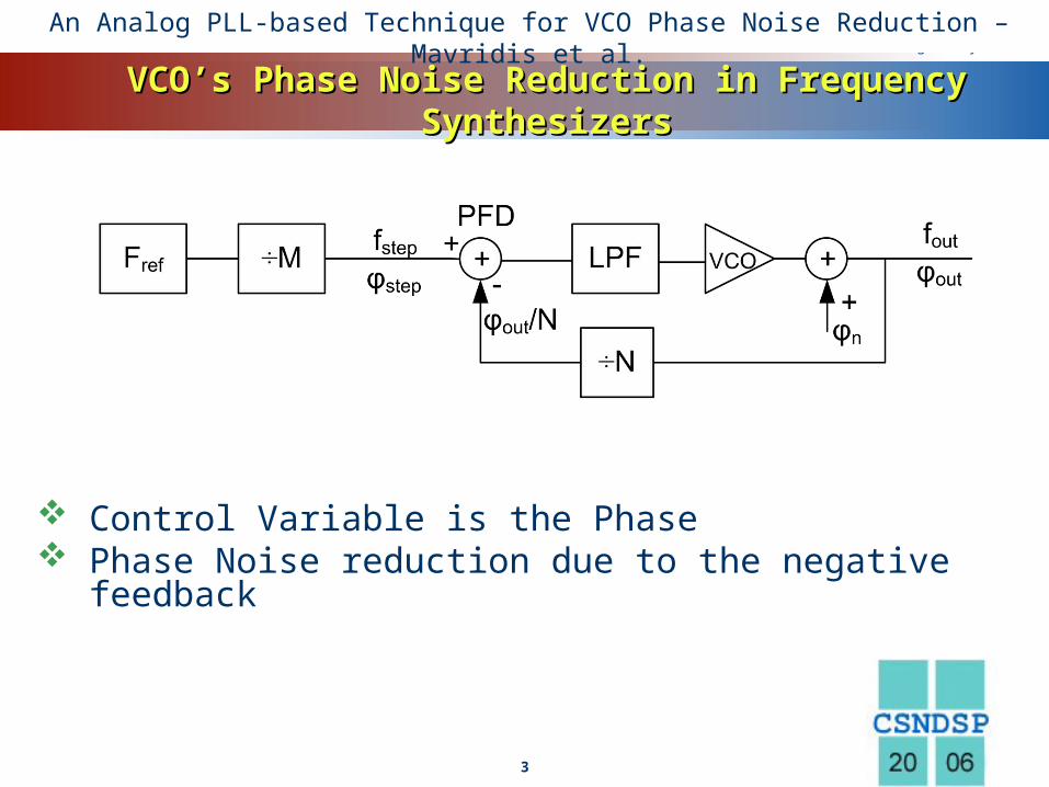
VCO’s Phase Noise Reduction in Frequency VCO’s Phase Noise Reduction in Frequency SynthesizersSynthesizers
Control Variable is the Phase Phase Noise reduction due to the negative
feedback
An Analog PLL-based Technique for VCO Phase Noise Reduction – Mavridis et al.
www.themegallery.com
Company Logo4
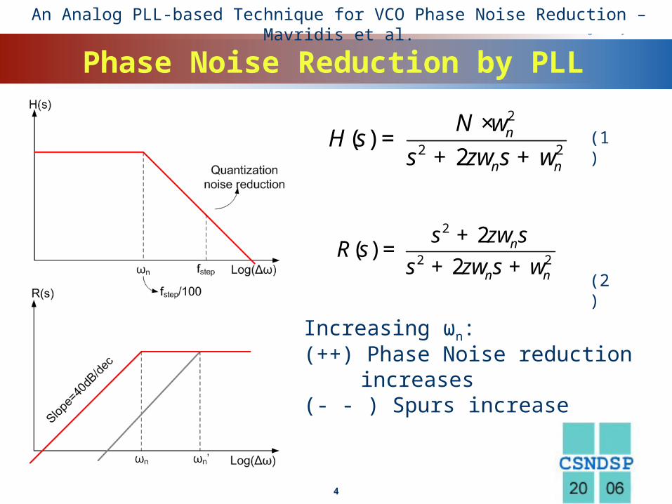
Phase Noise Reduction by PLL
Increasing ωn:(++) Phase Noise reduction
increases(- - ) Spurs increase
2
2 2
2( )
2n
n n
s sR s
s szw
zw w+
=+ +
2
2 2( )
2n
n n
NH s
s sw
zw w×
=+ +
(1)
(2)
An Analog PLL-based Technique for VCO Phase Noise Reduction – Mavridis et al.
www.themegallery.com
Company Logo5
Key point
Increase Sampling rate: Phase Information over a wide Bandwidth Quantization Noise at very high frequencies Large ωn values can be obtained
=> Increased Phase Noise Reduction
An Analog PLL-based Technique for VCO Phase Noise Reduction – Mavridis et al.
www.themegallery.com
Company Logo6
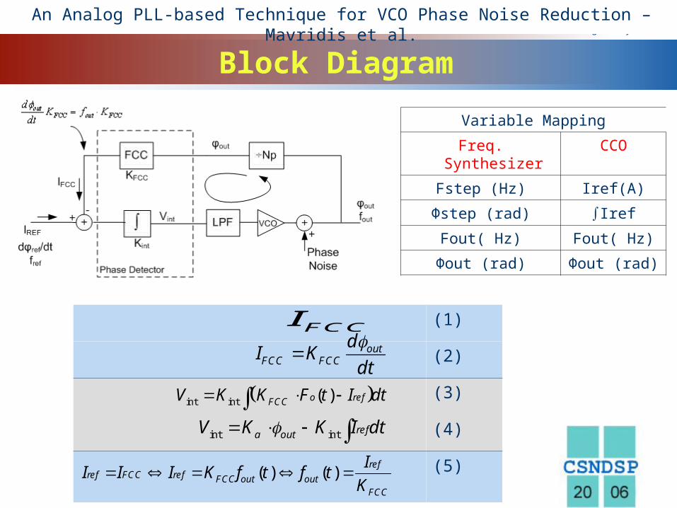
Block Diagram
Variable Mapping
Freq. Synthesizer CCO
Fstep (Hz) Iref(A)
Φstep (rad) ∫Iref
Fout( Hz) Fout( Hz)
Φout (rad) Φout (rad)
(1)
(2)
(3)
(4)
(5)
FCC FCC outI K f
outFCC FCC
dI K
dt
int int ( )o refFCCV K K F t I dt
int int refa outV K K I dt
( ) ( )ref
ref FCC ref FCC out outFCC
II I I K f t f t
K
An Analog PLL-based Technique for VCO Phase Noise Reduction – Mavridis et al.

www.themegallery.com
Company Logo7
CCO dynamics
Transfer Function2
2 2
2
2 2
( ) 1( )
( ) 2
( ) 2 1( )
( ) 2
o n
ref FCC n n
o n
ref FCC n n
F sG s
I s K s s
sP s
I s s K s s
(1)
(2)
(3)F +
= =F + +
2
2 2
( ) 2( )
( ) 2o n
n n n
s s sR s
s s szw
zw w
An Analog PLL-based Technique for VCO Phase Noise Reduction – Mavridis et al.
www.themegallery.com
Company Logo8
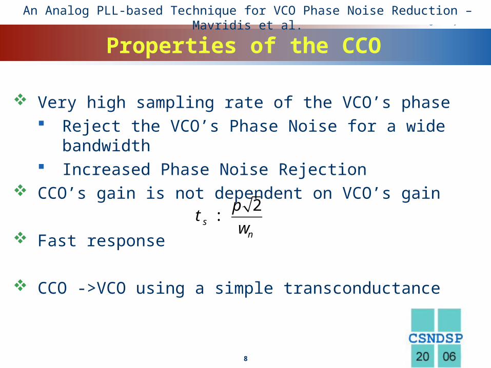
Properties of the CCO
Very high sampling rate of the VCO’s phase Reject the VCO’s Phase Noise for a wide bandwidth Increased Phase Noise Rejection
CCO’s gain is not dependent on VCO’s gain
Fast response
CCO ->VCO using a simple transconductance
2s
n
pt
w:
An Analog PLL-based Technique for VCO Phase Noise Reduction – Mavridis et al.
www.themegallery.com
Company Logo9
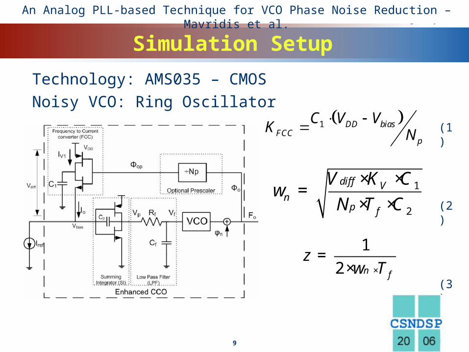
Simulation Setup
Technology: AMS035 – CMOSNoisy VCO: Ring Oscillator
(1)
(2)
(3)
1 DD biasFCC
p
C V VK N
× ×=
× ×1
2
diff Vn
p f
V K CN T C
w
12 n fT
zw ×
=×
An Analog PLL-based Technique for VCO Phase Noise Reduction – Mavridis et al.
www.themegallery.com
Company Logo10
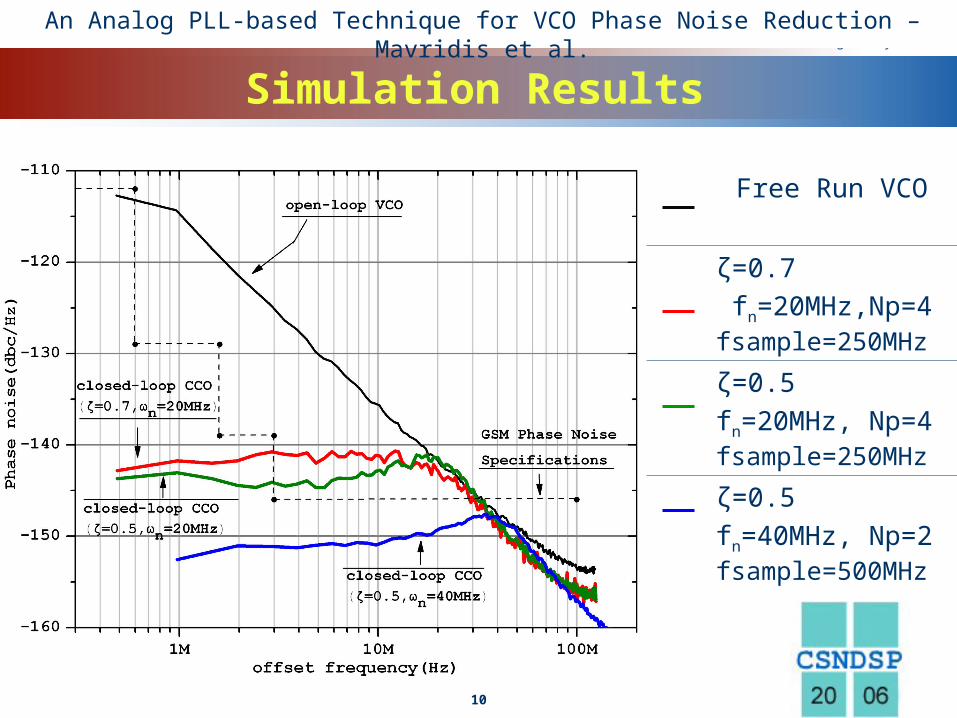
Simulation Results
Free Run VCO
ζ=0.7 fn=20MHz,Np=4 fsample=250MHz
ζ=0.5fn=20MHz, Np=4 fsample=250MHz
ζ=0.5fn=40MHz, Np=2 fsample=500MHz
An Analog PLL-based Technique for VCO Phase Noise Reduction – Mavridis et al.
www.themegallery.com
Company Logo11
Conclusion
Technique based on PLL Negligible circuitry Small Power overhead Small chip area
An Analog PLL-based Technique for VCO Phase Noise Reduction – Mavridis et al.

LOGO
Thank you for your attention!Thank you for your attention!