Embed Size (px)
Citation preview
Logix5000™ Controllers Import/Export1756 ControlLogix 1769 CompactLogix 1789 SoftLogix5800 1794 FlexLogix PowerFlex 700S with DriveLogix
Reference Manual
Important User Information Because of the variety of uses for the products described in this publication, those responsible for the application and use of this control equipment must satisfy themselves that all necessary steps have been taken to assure that each application and use meets all performance and safety requirements, including any applicable laws, regulations, codes and standards.
The illustrations, charts, sample programs and layout examples shown in this guide are intended solely for purposes of example. Since there are many variables and requirements associated with any particular installation, Allen-Bradley does not assume responsibility or liability (to include intellectual property liability) for actual use based upon the examples shown in this publication.
Allen-Bradley publication SGI-1.1, Safety Guidelines for the Application, Installation and Maintenance of Solid-State Control (available from your local Allen-Bradley office), describes some important differences between solid-state equipment and electromechanical devices that should be taken into consideration when applying products such as those described in this publication.
Reproduction of the contents of this copyrighted publication, in whole or part, without written permission of Rockwell Automation, is prohibited.
Throughout this manual we use notes to make you aware of safety considerations:
Attention and warning statements help you to:
• identify a hazard
• avoid a hazard
• recognize the consequences
Allen-Bradley, SLC 5/05, Compact, and ControlLogix are trademarks of Rockwell Automation.
RSLogix 5000, RSLogix 500, RSNetworx, and RSLinx are trademarks of Rockwell Software.
DeviceNet is a trademark of Open DeviceNet Vendor Association (ODVA).
ATTENTION
!Or ATTENTION
!Identifies information about practices or circumstances that can lead to personal injury or death, property damage or economic loss
IMPORTANT Identifies information that is critical for successful application and understanding of the product.

Summary of Changes
Summary of Changes This document describes how to use version 2.6 (major revision 2, minor revision 6) of the import/export feature that is included with RSLogix 5000 programming software, version 15. Changes made to this version of the manual include:
• Information about when an imported file modifies a project such that you cannot go online and access a previously downloaded controller (see page 1-10).
• Equipment Phase program type (see page 3-35) and its relay ladder and structured text instructions (see chapter 4 and 5 ).
• 1769-L32C CompactLogix and 1768-L43 CompactLogix controllers.
This release also removes support for the 1756-L1 ControlLogix, 1794-L33 FlexLogix, 1769-L20 CompactLogix, 1769-L30 CompactLogix, and PowerFlex 700 S controllers.
• Additional values for the Mode attribute of a MODULE component. (see page see page 3-6).
• New SERCOS IDN Read and SERCOS IDN Write message types (see page 3-18).
• New motion AXIS_GENERIC_DRIVE type (see page 3-20).
• ControlLogix and SoftLogix controllers now support 100 programs per task (see page 3-30)
• Removal of the DescriptionWidth parameter from the STEP, TRANSITION, and STOP components in SFC logic (see chapter 7).
• Addition of an Attributes column to the .CSV format for exported tags (see chapter 8).
1 Publication 1756-RM084K-EN-P - May 2005

Summary of Changes 2
Notes:
Publication 1756-RM084K-EN-P - May 2005

Table of Contents
Chapter 1
Import and Export Files Introduction . . . . . . . . . . . . . . . . . . . . . . . . . . . . . . . . . . . . . . . . . . . . . 1-1Export a Project to a Text File . . . . . . . . . . . . . . . . . . . . . . . . . . . . . . 1-2Import a Text File into a Project . . . . . . . . . . . . . . . . . . . . . . . . . . . . . 1-3Export to a .CSV File. . . . . . . . . . . . . . . . . . . . . . . . . . . . . . . . . . . . . . 1-5
Select the scope to export . . . . . . . . . . . . . . . . . . . . . . . . . . . . . . . 1-5Import a .CSV File . . . . . . . . . . . . . . . . . . . . . . . . . . . . . . . . . . . . . . . . 1-6Export to an .L5X File. . . . . . . . . . . . . . . . . . . . . . . . . . . . . . . . . . . . . 1-8Import an .L5X File . . . . . . . . . . . . . . . . . . . . . . . . . . . . . . . . . . . . . . . 1-9
Chapter 2
Structure a Complete (.L5K) Import/Export File Format
Introduction . . . . . . . . . . . . . . . . . . . . . . . . . . . . . . . . . . . . . . . . . . . . . 2-1Conventions . . . . . . . . . . . . . . . . . . . . . . . . . . . . . . . . . . . . . . . . . . . . . 2-1
Internal file comments. . . . . . . . . . . . . . . . . . . . . . . . . . . . . . . . . . 2-1Place Information in an Import/Export File . . . . . . . . . . . . . . . . . . . 2-2
Display style . . . . . . . . . . . . . . . . . . . . . . . . . . . . . . . . . . . . . . . . . . 2-3Component descriptions . . . . . . . . . . . . . . . . . . . . . . . . . . . . . . . . 2-3
Define a Controller . . . . . . . . . . . . . . . . . . . . . . . . . . . . . . . . . . . . . . . 2-4Specify CONTROLLER attributes . . . . . . . . . . . . . . . . . . . . . . . 2-5CONTROLLER guidelines. . . . . . . . . . . . . . . . . . . . . . . . . . . . . . 2-6CONTROLLER example . . . . . . . . . . . . . . . . . . . . . . . . . . . . . . . 2-6
Chapter 3
Create a Complete Import/Export File
Introduction . . . . . . . . . . . . . . . . . . . . . . . . . . . . . . . . . . . . . . . . . . . . . 3-1Define a Data Type . . . . . . . . . . . . . . . . . . . . . . . . . . . . . . . . . . . . . . . 3-1
Specify DATATYPE attributes . . . . . . . . . . . . . . . . . . . . . . . . . . 3-2Specify a DATATYPE member . . . . . . . . . . . . . . . . . . . . . . . . . . 3-2Specify DATATYPE member attributes . . . . . . . . . . . . . . . . . . . 3-4DATATYPE guidelines. . . . . . . . . . . . . . . . . . . . . . . . . . . . . . . . . 3-4DATATYPE example . . . . . . . . . . . . . . . . . . . . . . . . . . . . . . . . . . 3-4
Define a Module. . . . . . . . . . . . . . . . . . . . . . . . . . . . . . . . . . . . . . . . . . 3-5Specify MODULE attributes . . . . . . . . . . . . . . . . . . . . . . . . . . . . 3-5Specify a MODULE connection. . . . . . . . . . . . . . . . . . . . . . . . . . 3-8Specify MODULE connection attributes. . . . . . . . . . . . . . . . . . . 3-9MODULE guidelines . . . . . . . . . . . . . . . . . . . . . . . . . . . . . . . . . . 3-9MODULE example . . . . . . . . . . . . . . . . . . . . . . . . . . . . . . . . . . . 3-10
i Publication 1756-RM084K-EN-P - May 2005
ii
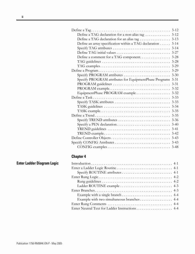
Define a Tag . . . . . . . . . . . . . . . . . . . . . . . . . . . . . . . . . . . . . . . . . . . . 3-12Define a TAG declaration for a non-alias tag . . . . . . . . . . . . . . 3-12Define a TAG declaration for an alias tag . . . . . . . . . . . . . . . . . 3-13Define an array specification within a TAG declaration . . . . . . 3-14Specify TAG attributes . . . . . . . . . . . . . . . . . . . . . . . . . . . . . . . . 3-14Define TAG initial values . . . . . . . . . . . . . . . . . . . . . . . . . . . . . . 3-27Define a comment for a TAG component. . . . . . . . . . . . . . . . . 3-28TAG guidelines . . . . . . . . . . . . . . . . . . . . . . . . . . . . . . . . . . . . . . 3-28TAG examples . . . . . . . . . . . . . . . . . . . . . . . . . . . . . . . . . . . . . . . 3-29
Define a Program . . . . . . . . . . . . . . . . . . . . . . . . . . . . . . . . . . . . . . . . 3-29Specify PROGRAM attributes . . . . . . . . . . . . . . . . . . . . . . . . . . 3-30Specify PROGRAM attributes for EquipmentPhase Programs 3-31PROGRAM guidelines . . . . . . . . . . . . . . . . . . . . . . . . . . . . . . . . 3-31PROGRAM example. . . . . . . . . . . . . . . . . . . . . . . . . . . . . . . . . . 3-32EquipmentPhase PROGRAM example . . . . . . . . . . . . . . . . . . . 3-32
Define a Task . . . . . . . . . . . . . . . . . . . . . . . . . . . . . . . . . . . . . . . . . . . 3-33Specify TASK attributes . . . . . . . . . . . . . . . . . . . . . . . . . . . . . . . 3-33TASK guidelines . . . . . . . . . . . . . . . . . . . . . . . . . . . . . . . . . . . . . 3-34TASK example. . . . . . . . . . . . . . . . . . . . . . . . . . . . . . . . . . . . . . . 3-35
Define a Trend . . . . . . . . . . . . . . . . . . . . . . . . . . . . . . . . . . . . . . . . . . 3-35Specify TREND attributes . . . . . . . . . . . . . . . . . . . . . . . . . . . . . 3-36Specify a PEN declaration. . . . . . . . . . . . . . . . . . . . . . . . . . . . . . 3-40TREND guidelines . . . . . . . . . . . . . . . . . . . . . . . . . . . . . . . . . . . 3-41TREND example. . . . . . . . . . . . . . . . . . . . . . . . . . . . . . . . . . . . . 3-42
Define Controller Objects . . . . . . . . . . . . . . . . . . . . . . . . . . . . . . . . . 3-43Specify CONFIG Attributes . . . . . . . . . . . . . . . . . . . . . . . . . . . . . . . 3-43
CONFIG examples . . . . . . . . . . . . . . . . . . . . . . . . . . . . . . . . . . . 3-48
Chapter 4
Enter Ladder Diagram Logic Introduction . . . . . . . . . . . . . . . . . . . . . . . . . . . . . . . . . . . . . . . . . . . . . 4-1Enter a Ladder Logic Routine . . . . . . . . . . . . . . . . . . . . . . . . . . . . . . . 4-1
Specify ROUTINE attributes . . . . . . . . . . . . . . . . . . . . . . . . . . . . 4-1Enter Rung Logic . . . . . . . . . . . . . . . . . . . . . . . . . . . . . . . . . . . . . . . . . 4-2
Rung guidelines . . . . . . . . . . . . . . . . . . . . . . . . . . . . . . . . . . . . . . . 4-2Ladder ROUTINE example . . . . . . . . . . . . . . . . . . . . . . . . . . . . . 4-3
Enter Branches . . . . . . . . . . . . . . . . . . . . . . . . . . . . . . . . . . . . . . . . . . . 4-3Example with a single branch . . . . . . . . . . . . . . . . . . . . . . . . . . . . 4-4Example with two simultaneous branches . . . . . . . . . . . . . . . . . . 4-4
Enter Rung Comments . . . . . . . . . . . . . . . . . . . . . . . . . . . . . . . . . . . . 4-4Enter Neutral Text for Ladder Instructions . . . . . . . . . . . . . . . . . . . . 4-4
Publication 1756-RM084K-EN-P - May 2005

iii
Chapter 5
Enter Function Block Diagram Logic
Introduction . . . . . . . . . . . . . . . . . . . . . . . . . . . . . . . . . . . . . . . . . . . . . 5-1Enter a Function Block Diagram Routine . . . . . . . . . . . . . . . . . . . . . 5-1
Specify FBD_ROUTINE attributes . . . . . . . . . . . . . . . . . . . . . . . 5-2Enter Function Block Diagram Logic. . . . . . . . . . . . . . . . . . . . . . . . . 5-2
SHEET guidelines . . . . . . . . . . . . . . . . . . . . . . . . . . . . . . . . . . . . . 5-3FBD_ROUTINE example . . . . . . . . . . . . . . . . . . . . . . . . . . . . . . 5-4
Export Function Block Logic While Editing Online . . . . . . . . . . . . . 5-6Enter IREFs and OREFs . . . . . . . . . . . . . . . . . . . . . . . . . . . . . . . . . . 5-7
IREF and OREF guidelines . . . . . . . . . . . . . . . . . . . . . . . . . . . . . 5-8IREF and OREF examples . . . . . . . . . . . . . . . . . . . . . . . . . . . . . . 5-8
Enter ICONs and OCONs . . . . . . . . . . . . . . . . . . . . . . . . . . . . . . . . . 5-9ICON and OCON guidelines . . . . . . . . . . . . . . . . . . . . . . . . . . . . 5-9ICON and OCON examples . . . . . . . . . . . . . . . . . . . . . . . . . . . 5-10
Enter Wires and Feedback Wires . . . . . . . . . . . . . . . . . . . . . . . . . . . 5-10WIRE guidelines . . . . . . . . . . . . . . . . . . . . . . . . . . . . . . . . . . . . . 5-11WIRE example. . . . . . . . . . . . . . . . . . . . . . . . . . . . . . . . . . . . . . . 5-11
Enter Blocks . . . . . . . . . . . . . . . . . . . . . . . . . . . . . . . . . . . . . . . . . . . . 5-11BLOCK guidelines. . . . . . . . . . . . . . . . . . . . . . . . . . . . . . . . . . . . 5-12
Enter Parameters for Function Block Instructions . . . . . . . . . . . . . 5-13
Chapter 6
Enter Structured Text Logic Introduction . . . . . . . . . . . . . . . . . . . . . . . . . . . . . . . . . . . . . . . . . . . . . 6-1Enter a Structured Text Routine . . . . . . . . . . . . . . . . . . . . . . . . . . . . . 6-1
Specify ST_ROUTINE attributes. . . . . . . . . . . . . . . . . . . . . . . . . 6-1Enter Structured Text Logic . . . . . . . . . . . . . . . . . . . . . . . . . . . . . . . . 6-2
Structured text ST_ROUTINE example . . . . . . . . . . . . . . . . . . . 6-3Enter Comments . . . . . . . . . . . . . . . . . . . . . . . . . . . . . . . . . . . . . . . . . 6-3Export Structured Text Logic While Editing Online . . . . . . . . . . . . . 6-4Enter Structured Text . . . . . . . . . . . . . . . . . . . . . . . . . . . . . . . . . . . . . 6-5
Chapter 7
Enter Sequential Function Chart Logic
Introduction . . . . . . . . . . . . . . . . . . . . . . . . . . . . . . . . . . . . . . . . . . . . . 7-1Enter a Sequential Function Chart Routine . . . . . . . . . . . . . . . . . . . . 7-1
Specify SFC_ROUTINE attributes . . . . . . . . . . . . . . . . . . . . . . . 7-3SFC_ROUTINE example . . . . . . . . . . . . . . . . . . . . . . . . . . . . . . . 7-4
Export Sequentical Function Chart Logic While Editing Online . . . 7-9Enter Steps . . . . . . . . . . . . . . . . . . . . . . . . . . . . . . . . . . . . . . . . . . . . . 7-11
Enter a PRESET block . . . . . . . . . . . . . . . . . . . . . . . . . . . . . . . . 7-12Enter a LIMIT_HIGH block . . . . . . . . . . . . . . . . . . . . . . . . . . . 7-13Enter a LIMIT_LOW block . . . . . . . . . . . . . . . . . . . . . . . . . . . . 7-13Enter an ACTION_LIST block . . . . . . . . . . . . . . . . . . . . . . . . . 7-13STEP example . . . . . . . . . . . . . . . . . . . . . . . . . . . . . . . . . . . . . . . 7-15
Publication 1756-RM084K-EN-P - May 2005
iv
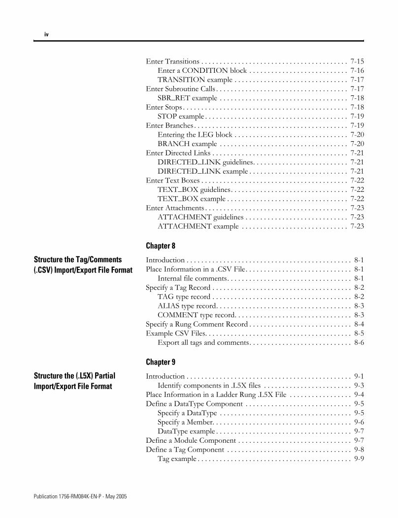
Enter Transitions . . . . . . . . . . . . . . . . . . . . . . . . . . . . . . . . . . . . . . . . 7-15Enter a CONDITION block . . . . . . . . . . . . . . . . . . . . . . . . . . . 7-16TRANSITION example . . . . . . . . . . . . . . . . . . . . . . . . . . . . . . . 7-17
Enter Subroutine Calls . . . . . . . . . . . . . . . . . . . . . . . . . . . . . . . . . . . . 7-17SBR_RET example . . . . . . . . . . . . . . . . . . . . . . . . . . . . . . . . . . . 7-18
Enter Stops . . . . . . . . . . . . . . . . . . . . . . . . . . . . . . . . . . . . . . . . . . . . . 7-18STOP example . . . . . . . . . . . . . . . . . . . . . . . . . . . . . . . . . . . . . . . 7-19
Enter Branches . . . . . . . . . . . . . . . . . . . . . . . . . . . . . . . . . . . . . . . . . . 7-19Entering the LEG block . . . . . . . . . . . . . . . . . . . . . . . . . . . . . . . 7-20BRANCH example . . . . . . . . . . . . . . . . . . . . . . . . . . . . . . . . . . . 7-20
Enter Directed Links . . . . . . . . . . . . . . . . . . . . . . . . . . . . . . . . . . . . . 7-21DIRECTED_LINK guidelines. . . . . . . . . . . . . . . . . . . . . . . . . . 7-21DIRECTED_LINK example . . . . . . . . . . . . . . . . . . . . . . . . . . . 7-21
Enter Text Boxes . . . . . . . . . . . . . . . . . . . . . . . . . . . . . . . . . . . . . . . . 7-22TEXT_BOX guidelines. . . . . . . . . . . . . . . . . . . . . . . . . . . . . . . . 7-22TEXT_BOX example . . . . . . . . . . . . . . . . . . . . . . . . . . . . . . . . . 7-22
Enter Attachments . . . . . . . . . . . . . . . . . . . . . . . . . . . . . . . . . . . . . . . 7-23ATTACHMENT guidelines . . . . . . . . . . . . . . . . . . . . . . . . . . . . 7-23ATTACHMENT example . . . . . . . . . . . . . . . . . . . . . . . . . . . . . 7-23
Chapter 8
Structure the Tag/Comments (.CSV) Import/Export File Format
Introduction . . . . . . . . . . . . . . . . . . . . . . . . . . . . . . . . . . . . . . . . . . . . . 8-1Place Information in a .CSV File. . . . . . . . . . . . . . . . . . . . . . . . . . . . . 8-1
Internal file comments. . . . . . . . . . . . . . . . . . . . . . . . . . . . . . . . . . 8-1Specify a Tag Record . . . . . . . . . . . . . . . . . . . . . . . . . . . . . . . . . . . . . . 8-2
TAG type record . . . . . . . . . . . . . . . . . . . . . . . . . . . . . . . . . . . . . . 8-2ALIAS type record. . . . . . . . . . . . . . . . . . . . . . . . . . . . . . . . . . . . . 8-3COMMENT type record. . . . . . . . . . . . . . . . . . . . . . . . . . . . . . . . 8-3
Specify a Rung Comment Record . . . . . . . . . . . . . . . . . . . . . . . . . . . . 8-4Example CSV Files. . . . . . . . . . . . . . . . . . . . . . . . . . . . . . . . . . . . . . . . 8-5
Export all tags and comments. . . . . . . . . . . . . . . . . . . . . . . . . . . . 8-6
Chapter 9
Structure the (.L5X) Partial Import/Export File Format
Introduction . . . . . . . . . . . . . . . . . . . . . . . . . . . . . . . . . . . . . . . . . . . . . 9-1Identify components in .L5X files . . . . . . . . . . . . . . . . . . . . . . . . 9-3
Place Information in a Ladder Rung .L5X File . . . . . . . . . . . . . . . . . 9-4Define a DataType Component . . . . . . . . . . . . . . . . . . . . . . . . . . . . . 9-5
Specify a DataType . . . . . . . . . . . . . . . . . . . . . . . . . . . . . . . . . . . . 9-5Specify a Member. . . . . . . . . . . . . . . . . . . . . . . . . . . . . . . . . . . . . . 9-6DataType example . . . . . . . . . . . . . . . . . . . . . . . . . . . . . . . . . . . . . 9-7
Define a Module Component . . . . . . . . . . . . . . . . . . . . . . . . . . . . . . . 9-7Define a Tag Component . . . . . . . . . . . . . . . . . . . . . . . . . . . . . . . . . . 9-8
Tag example . . . . . . . . . . . . . . . . . . . . . . . . . . . . . . . . . . . . . . . . . . 9-9
Publication 1756-RM084K-EN-P - May 2005
v
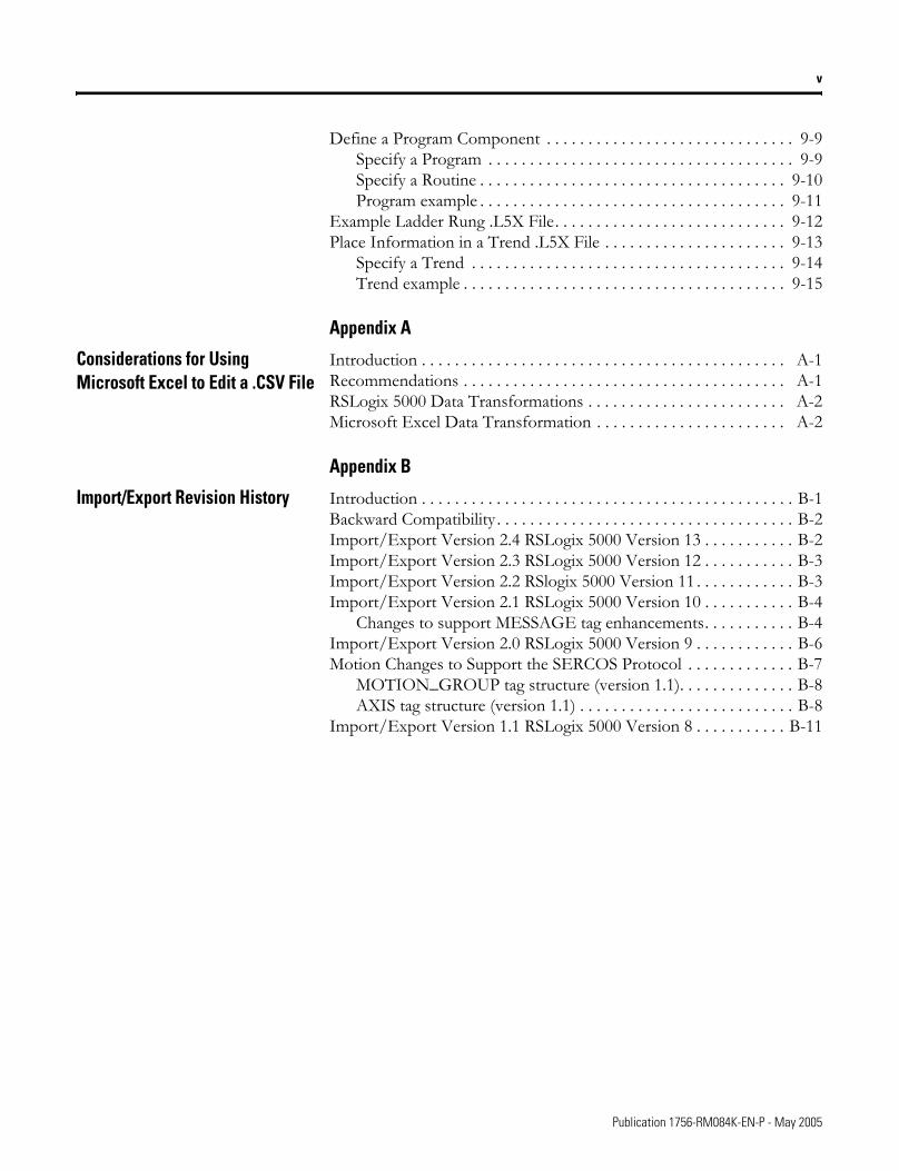
Define a Program Component . . . . . . . . . . . . . . . . . . . . . . . . . . . . . . 9-9Specify a Program . . . . . . . . . . . . . . . . . . . . . . . . . . . . . . . . . . . . . 9-9Specify a Routine . . . . . . . . . . . . . . . . . . . . . . . . . . . . . . . . . . . . . 9-10Program example . . . . . . . . . . . . . . . . . . . . . . . . . . . . . . . . . . . . . 9-11
Example Ladder Rung .L5X File. . . . . . . . . . . . . . . . . . . . . . . . . . . . 9-12Place Information in a Trend .L5X File . . . . . . . . . . . . . . . . . . . . . . 9-13
Specify a Trend . . . . . . . . . . . . . . . . . . . . . . . . . . . . . . . . . . . . . . 9-14Trend example . . . . . . . . . . . . . . . . . . . . . . . . . . . . . . . . . . . . . . . 9-15
Appendix A
Considerations for Using Microsoft Excel to Edit a .CSV File
Introduction . . . . . . . . . . . . . . . . . . . . . . . . . . . . . . . . . . . . . . . . . . . . A-1Recommendations . . . . . . . . . . . . . . . . . . . . . . . . . . . . . . . . . . . . . . . A-1RSLogix 5000 Data Transformations . . . . . . . . . . . . . . . . . . . . . . . . A-2Microsoft Excel Data Transformation . . . . . . . . . . . . . . . . . . . . . . . A-2
Appendix B
Import/Export Revision History Introduction . . . . . . . . . . . . . . . . . . . . . . . . . . . . . . . . . . . . . . . . . . . . . B-1Backward Compatibility . . . . . . . . . . . . . . . . . . . . . . . . . . . . . . . . . . . . B-2Import/Export Version 2.4 RSLogix 5000 Version 13 . . . . . . . . . . . B-2Import/Export Version 2.3 RSLogix 5000 Version 12 . . . . . . . . . . . B-3Import/Export Version 2.2 RSlogix 5000 Version 11 . . . . . . . . . . . . B-3Import/Export Version 2.1 RSLogix 5000 Version 10 . . . . . . . . . . . B-4
Changes to support MESSAGE tag enhancements. . . . . . . . . . . B-4Import/Export Version 2.0 RSLogix 5000 Version 9 . . . . . . . . . . . . B-6Motion Changes to Support the SERCOS Protocol . . . . . . . . . . . . . B-7
MOTION_GROUP tag structure (version 1.1). . . . . . . . . . . . . . B-8AXIS tag structure (version 1.1) . . . . . . . . . . . . . . . . . . . . . . . . . . B-8
Import/Export Version 1.1 RSLogix 5000 Version 8 . . . . . . . . . . . B-11
Publication 1756-RM084K-EN-P - May 2005

vi
Notes:
Publication 1756-RM084K-EN-P - May 2005
Chapter 1
Import and Export Files
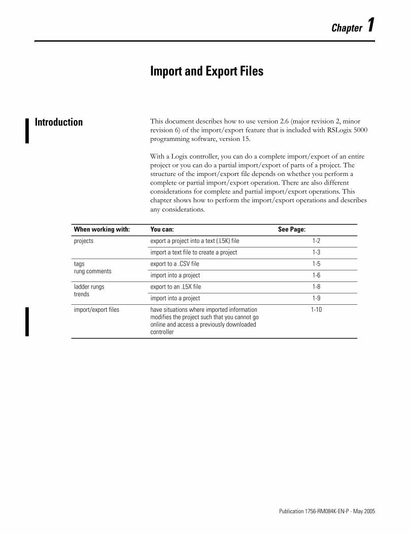
Introduction This document describes how to use version 2.6 (major revision 2, minor revision 6) of the import/export feature that is included with RSLogix 5000 programming software, version 15.
With a Logix controller, you can do a complete import/export of an entire project or you can do a partial import/export of parts of a project. The structure of the import/export file depends on whether you perform a complete or partial import/export operation. There are also different considerations for complete and partial import/export operations. This chapter shows how to perform the import/export operations and describes any considerations.
When working with: You can: See Page:
projects export a project into a text (.L5K) file 1-2
import a text file to create a project 1-3
tagsrung comments
export to a .CSV file 1-5
import into a project 1-6
ladder rungs trends
export to an .L5X file 1-8
import into a project 1-9
import/export files have situations where imported information modifies the project such that you cannot go online and access a previously downloaded controller
1-10
1 Publication 1756-RM084K-EN-P - May 2005
1-2 Import and Export Files
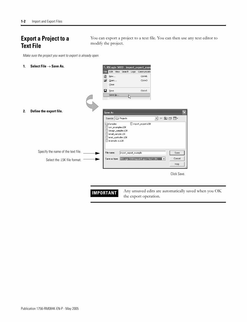
Export a Project to a Text File
You can export a project to a text file. You can then use any text editor to modify the project.
1. Select File → Save As.
2. Define the export file.
Click Save.
Make sure the project you want to export is already open.
Specify the name of the text file.
Select the .L5K file format.
IMPORTANT Any unsaved edits are automatically saved when you OK the export operation.
Publication 1756-RM084K-EN-P - May 2005
Import and Export Files 1-3
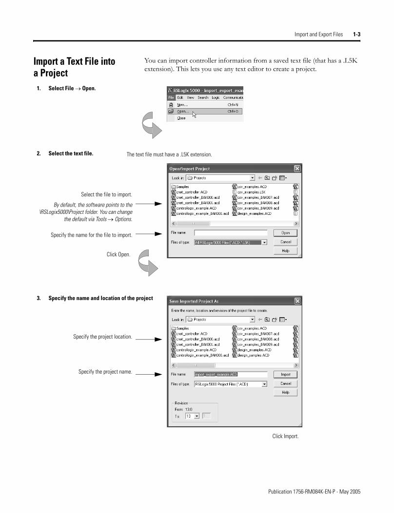
Import a Text File into a Project
You can import controller information from a saved text file (that has a .L5K extension). This lets you use any text editor to create a project.
1. Select File → Open.
2. Select the text file.
Select the file to import.
By default, the software points to the \RSLogix5000\Project folder. You can change
the default via Tools → Options.
Specify the name for the file to import.
Click Open.
The text file must have a .L5K extension.
3. Specify the name and location of the project
Specify the project name.
Specify the project location.
Click Import.
Publication 1756-RM084K-EN-P - May 2005
1-4 Import and Export Files
If you import a project that has forces, the project defaults to Forces Disabled, even if the project was exported with Forces Enabled.
For more information about the structure of the complete import/export file, see:
For information on how to: See chapter:
structure a complete import/export file 2
create a complete import/export file 3
enter relay ladder logic 4
enter function block diagram logic 5
enter structured text logic 6
enter sequential function chart logic 7
IMPORTANT When you import a .L5K file, the project changes such that you cannot go online and access a previously downloaded controller. You will have to first upload from or download to the controller. See page 1-10.
Publication 1756-RM084K-EN-P - May 2005
Import and Export Files 1-5
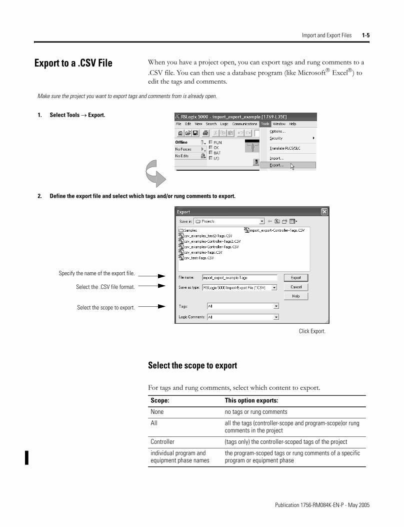
Export to a .CSV File When you have a project open, you can export tags and rung comments to a .CSV file. You can then use a database program (like Microsoft® Excel®) to edit the tags and comments.
Select the scope to export
For tags and rung comments, select which content to export.
1. Select Tools → Export.
2. Define the export file and select which tags and/or rung comments to export.
Click Export.
Make sure the project you want to export tags and comments from is already open.
Specify the name of the export file.
Select the .CSV file format.
Select the scope to export.
Scope: This option exports:
None no tags or rung comments
All all the tags (controller-scope and program-scope)or rung comments in the project
Controller (tags only) the controller-scoped tags of the project
individual program and equipment phase names
the program-scoped tags or rung comments of a specific program or equipment phase
Publication 1756-RM084K-EN-P - May 2005
1-6 Import and Export Files
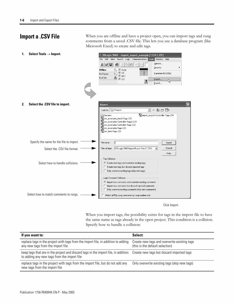
Import a .CSV File When you are offline and have a project open, you can import tags and rung comments from a saved .CSV file. This lets you use a database program (like Microsoft Excel) to create and edit tags.
When you import tags, the possibility exists for tags in the import file to have the same name as tags already in the open project. This condition is a collision. Specify how to handle a collision:
1. Select Tools → Import.
2. Select the .CSV file to import.
Specify the name for the file to import.
Click Import.
Select the .CSV file format.
Select how to handle collisions.
Select how to match comments to rungs.
If you want to: Select:
replace tags in the project with tags from the import file, in addition to adding any new tags from the import file
Create new tags and overwrite existing tags(this is the default selection)
keep tags that are in the project and discard tags in the import file, in addition to adding any new tags from the import file
Create new tags but discard imported tags
replace tags in the project with tags from the import file, but do not add any new tags from the import file
Only overwrite existing tags (skip new tags)
Publication 1756-RM084K-EN-P - May 2005
Import and Export Files 1-7
If you delete tags from an import/export file and then import the file, tags are not deleted from the controller project. You have to use the programming software to delete tags from the tag list.
When you import rung comments, the possibility exists for comments in the import file to differ from comments in the open project when both are matched to the same rung. Specify how to handle a collision:
Also select whether to match comments to rungs based on rung numbers or on owning element information:
For more information about the structure of the partial import/export file for tags and rung comments, see:
If you want to: Select:
replace comments in the project with comments from the import file, in addition to adding any new comments from the import file
Import new comments and overwrite existing comments(this is the default selection)
keep comments that are in the project and discard comments in the import file, in addition to adding any new comments from the import file
Import new comments but discard imported comments
replace comments in the project with comments from the import file, but do not add any new comments from the import file
Only overwrite existing comments (skip new comments)
If you want rung comments applied to: Then in the “Match all RLL comments to rung number only” box:
the next rung that has the instruction, as specified in the Owning Element, as its last instruction on the rungthis is the default and recommended optionthe Location element is ignored
leave the box unchecked
the rung number specified in the Location elementthis overrides the default and recommended optionthe Owning Element is ignored
check the box
For information on how to: See chapter:
structure a partial import/export .CSV file 8
IMPORTANT If a .CSV file contains changes to tags (including aliases), when you import the file, the project changes such that you cannot go online and access a previously downloaded controller. You will have to first upload from or download to the controller. See page 1-10.
If you only modify comments or descriptions before you import a .CSV file, you can go online with the controller.
Publication 1756-RM084K-EN-P - May 2005
1-8 Import and Export Files
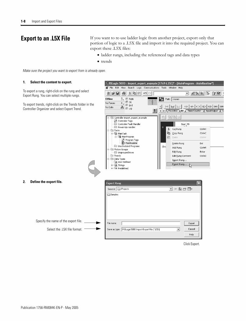
Export to an .L5X File If you want to re-use ladder logic from another project, export only that portion of logic to a .L5X file and import it into the required project. You can export these .L5X files:
• ladder rungs, including the referenced tags and data types• trends
1. Select the content to export.
To export a rung, right-click on the rung and select Export Rung. You can select multiple rungs.
To export trends, right-click on the Trends folder in the Controller Organizer and select Export Trend.
2. Define the export file.
Click Export.
Make sure the project you want to export from is already open.
Specify the name of the export file.
Select the .L5X file format.
Publication 1756-RM084K-EN-P - May 2005
Import and Export Files 1-9
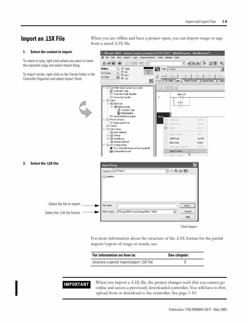
Import an .L5X File When you are offline and have a project open, you can import rungs or tags from a saved .L5X file.
For more information about the structure of the .L5X format for the partial import/export of rungs or trends, see:
2. Select the .L5X file.
Select the file to import.
Click Import.
Select the .L5X file format.
1. Select the content to import.
To import a rung, right-click where you want to insert the imported rungs and select Import Rung.
To import trends, right-click on the Trends folder in the Controller Organizer and select Import Trend
For information on how to: See chapter:
structure a partial import/export .L5X file 9
IMPORTANT When you import a .L5X file, the project changes such that you cannot go online and access a previously downloaded controller. You will have to first upload from or download to the controller. See page 1-10.
Publication 1756-RM084K-EN-P - May 2005
1-10 Import and Export Files
Maintaining Controller Access
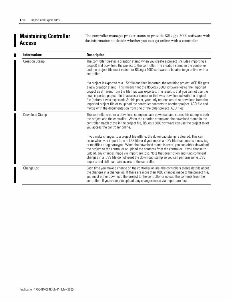
The controller manages project status to provide RSLogix 5000 software with the information to decide whether you can go online with a controller.
Information: Description:
Creation Stamp The controller creates a creation stamp when you create a project (includes importing a project) and download the project to the controller. The creation stamp in the controller and the project file must match for RSLogix 5000 software to be able to go online with a controller.
If a project is exported to a .L5K file and then imported, the resulting project .ACD file gets a new creation stamp. This means that the RSLogix 5000 software views the imported project as different from the file that was exported. The result is that you cannot use the new, imported project file to access a controller that was downloaded with the original file (before it was exported). At this point, your only options are to re-download from the imported project file or to upload the controller contents to another project .ACD file and merge with the documentation from one of the older project .ACD files.
Download Stamp The controller creates a download stamp on each download and stores this stamp in both the project and the controller. When the creation stamp and the download stamp in the controller match those in the project file, RSLogix 5000 software can use the project to let you access the controller online.
If you make changes to a project file offline, the download stamp is cleared. This can occur when you import from a .L5X file or if you import a .CSV file that creates a new tag or modifies a tag datatype. When the download stamp is reset, you can either download the project to the controller or upload the contents from the controller. If you choose to upload, any changes made via import are lost. Note that description and rung comment changes in a .CSV file do not reset the download stamp so you can perform some .CSV imports and still maintain access to the controller.
Change Log Each time you make a change on the controller online, the controllers stores details about the changes in a change log. If there are more than 1000 changes made to the project file, you must either download the project to the controller or upload the contents from the controller. If you choose to upload, any changes made via import are lost.
Publication 1756-RM084K-EN-P - May 2005
Import and Export Files 1-11
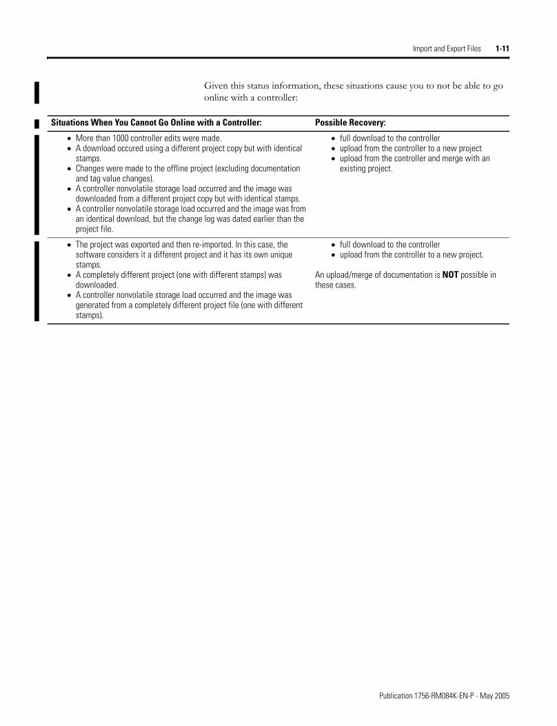
Given this status information, these situations cause you to not be able to go online with a controller:
Situations When You Cannot Go Online with a Controller: Possible Recovery:
• More than 1000 controller edits were made.• A download occured using a different project copy but with identical
stamps.• Changes were made to the offline project (excluding documentation
and tag value changes).• A controller nonvolatile storage load occurred and the image was
downloaded from a different project copy but with identical stamps.• A controller nonvolatile storage load occurred and the image was from
an identical download, but the change log was dated earlier than the project file.
• full download to the controller• upload from the controller to a new project• upload from the controller and merge with an
existing project.
• The project was exported and then re-imported. In this case, the software considers it a different project and it has its own unique stamps.
• A completely different project (one with different stamps) was downloaded.
• A controller nonvolatile storage load occurred and the image was generated from a completely different project file (one with different stamps).
• full download to the controller• upload from the controller to a new project.
An upload/merge of documentation is NOT possible in these cases.
Publication 1756-RM084K-EN-P - May 2005

1-12 Import and Export Files
Notes:
Publication 1756-RM084K-EN-P - May 2005
Chapter 2
Structure a Complete (.L5K) Import/Export File Format
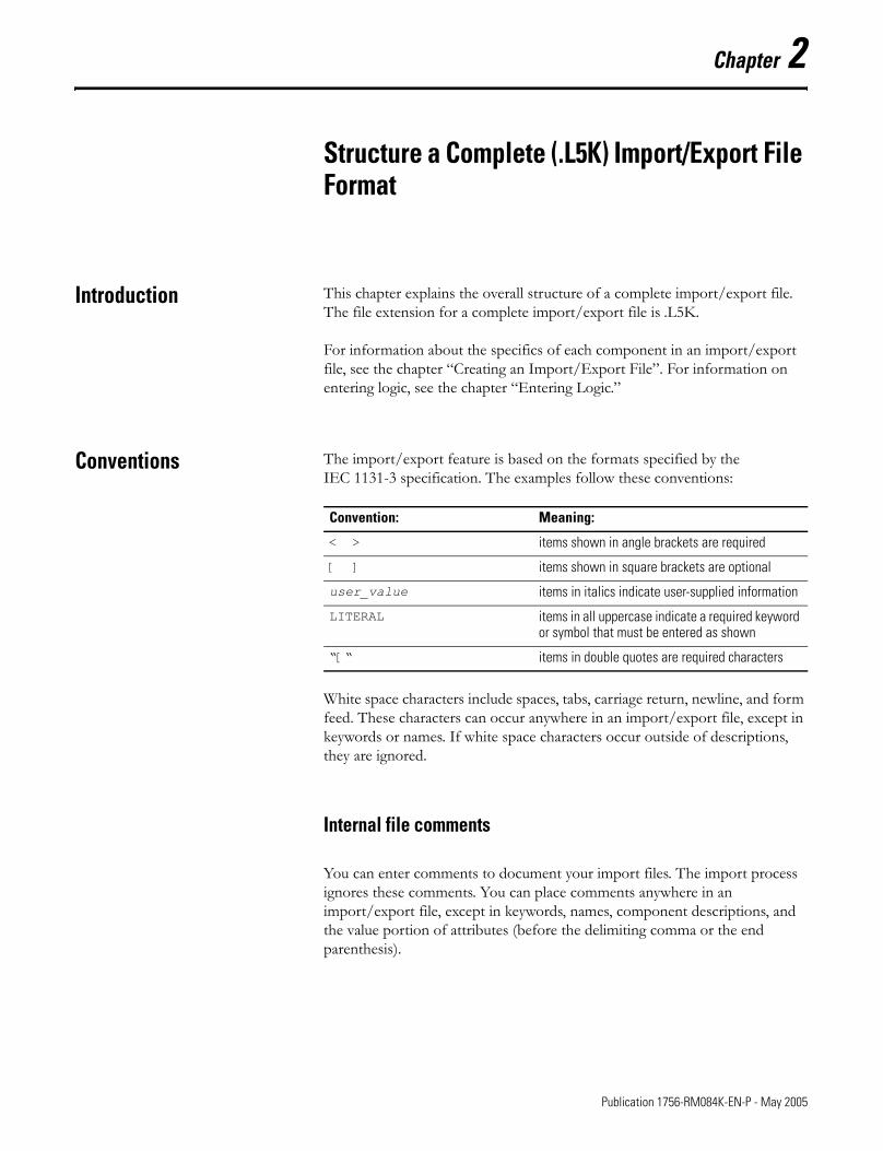
Introduction This chapter explains the overall structure of a complete import/export file. The file extension for a complete import/export file is .L5K.
For information about the specifics of each component in an import/export file, see the chapter �Creating an Import/Export File�. For information on entering logic, see the chapter �Entering Logic.�
Conventions The import/export feature is based on the formats specified by the IEC 1131-3 specification. The examples follow these conventions:
White space characters include spaces, tabs, carriage return, newline, and form feed. These characters can occur anywhere in an import/export file, except in keywords or names. If white space characters occur outside of descriptions, they are ignored.
Internal file comments
You can enter comments to document your import files. The import process ignores these comments. You can place comments anywhere in an import/export file, except in keywords, names, component descriptions, and the value portion of attributes (before the delimiting comma or the end parenthesis).
Convention: Meaning:
< > items shown in angle brackets are required
[ ] items shown in square brackets are optional
user_value items in italics indicate user-supplied information
LITERAL items in all uppercase indicate a required keyword or symbol that must be entered as shown
�[� items in double quotes are required characters
1 Publication 1756-RM084K-EN-P - May 2005
2-2 Structure a Complete (.L5K) Import/Export File Format
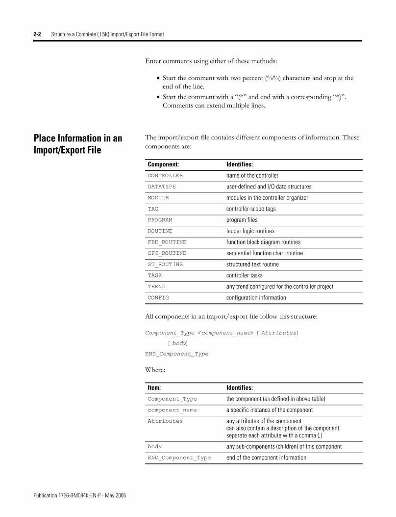
Enter comments using either of these methods:
• Start the comment with two percent (%%) characters and stop at the end of the line.
• Start the comment with a �(*� and end with a corresponding �*)�. Comments can extend multiple lines.
Place Information in an Import/Export File
The import/export file contains different components of information. These components are:
All components in an import/export file follow this structure:
Component_Type <component_name> [Attributes]
[body]
END_Component_Type
Where:
Component: Identifies:
CONTROLLER name of the controller
DATATYPE user-defined and I/O data structures
MODULE modules in the controller organizer
TAG controller-scope tags
PROGRAM program files
ROUTINE ladder logic routines
FBD_ROUTINE function block diagram routines
SFC_ROUTINE sequential function chart routine
ST_ROUTINE structured text routine
TASK controller tasks
TREND any trend configured for the controller project
CONFIG configuration information
Item: Identifies:
Component_Type the component (as defined in above table)
component_name a specific instance of the component
Attributes any attributes of the componentcan also contain a description of the componentseparate each attribute with a comma (,)
body any sub-components (children) of this component
END_Component_Type end of the component information
Publication 1756-RM084K-EN-P - May 2005
Structure a Complete (.L5K) Import/Export File Format 2-3
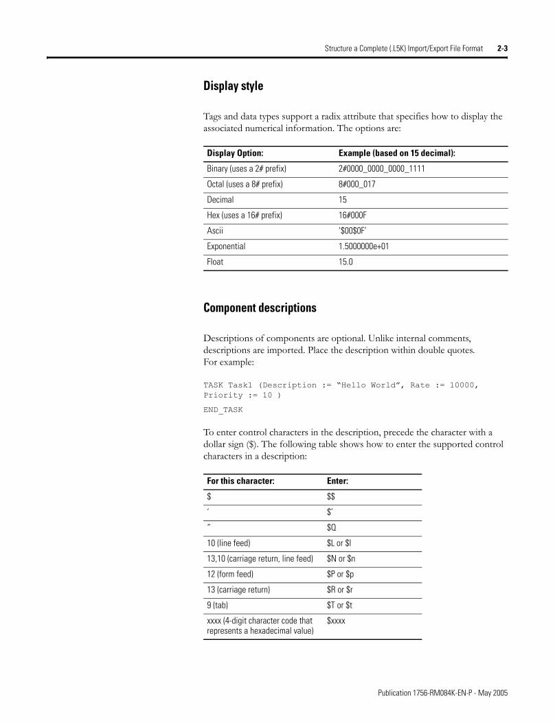
Display style
Tags and data types support a radix attribute that specifies how to display the associated numerical information. The options are:
Component descriptions
Descriptions of components are optional. Unlike internal comments, descriptions are imported. Place the description within double quotes. For example:
TASK Task1 (Description := �Hello World�, Rate := 10000, Priority := 10 )
END_TASK
To enter control characters in the description, precede the character with a dollar sign ($). The following table shows how to enter the supported control characters in a description:
Display Option: Example (based on 15 decimal):
Binary (uses a 2# prefix) 2#0000_0000_0000_1111
Octal (uses a 8# prefix) 8#000_017
Decimal 15
Hex (uses a 16# prefix) 16#000F
Ascii ‘$00$0F’
Exponential 1.5000000e+01
Float 15.0
For this character: Enter:
$ $$
‘ $’
“ $Q
10 (line feed) $L or $l
13,10 (carriage return, line feed) $N or $n
12 (form feed) $P or $p
13 (carriage return) $R or $r
9 (tab) $T or $t
xxxx (4-digit character code that represents a hexadecimal value)
$xxxx
Publication 1756-RM084K-EN-P - May 2005
2-4 Structure a Complete (.L5K) Import/Export File Format
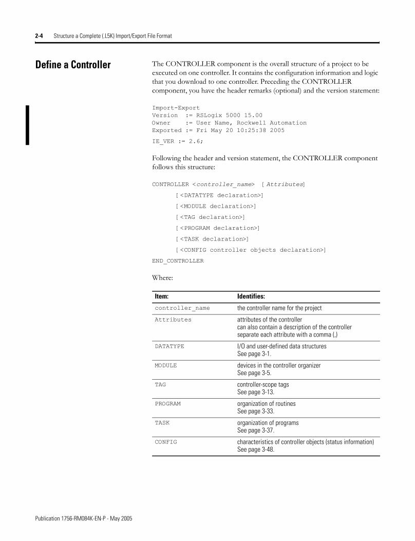
Define a Controller The CONTROLLER component is the overall structure of a project to be executed on one controller. It contains the configuration information and logic that you download to one controller. Preceding the CONTROLLER component, you have the header remarks (optional) and the version statement:
Import-Export Version := RSLogix 5000 15.00 Owner := User Name, Rockwell Automation Exported := Fri May 20 10:25:38 2005
IE_VER := 2.6;
Following the header and version statement, the CONTROLLER component follows this structure:
CONTROLLER <controller_name> [Attributes]
[<DATATYPE declaration>]
[<MODULE declaration>]
[<TAG declaration>]
[<PROGRAM declaration>]
[<TASK declaration>]
[<CONFIG controller objects declaration>]
END_CONTROLLER
Where:
Item: Identifies:
controller_name the controller name for the project
Attributes attributes of the controllercan also contain a description of the controllerseparate each attribute with a comma (,)
DATATYPE I/O and user-defined data structuresSee page 3-1.
MODULE devices in the controller organizerSee page 3-5.
TAG controller-scope tagsSee page 3-13.
PROGRAM organization of routinesSee page 3-33.
TASK organization of programsSee page 3-37.
CONFIG characteristics of controller objects (status information)See page 3-48.
Publication 1756-RM084K-EN-P - May 2005
Structure a Complete (.L5K) Import/Export File Format 2-5
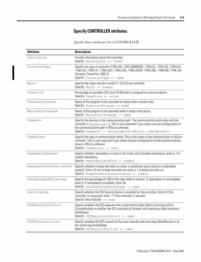
Specify CONTROLLER attributes
Specify these attributes for a CONTROLLER:
Attribute: Description:
Description Provide information about the controller.Specify: Description := �text�
ProcessorType Specify the type of controller (1756-L55, 1756-L60M03SE, 1756-L61, 1756-L62, 1756-L63, 1768-L43, 1769-L31, 1769-L32C, 1769-L32E, 1769-L35CR, 1769-L35E, 1789-L60, 1794-L34, Emulator, PowerFlex 700S 2)Specify: ProcessorType := name
Major Specify the major revision number (1-127) of the controller.Specify: Major := number
TimeSlice Percentage of available CPU time (10-90) that is assigned to communications.Specify: TimeSlice := value
PowerLossProgram Name of the program to be executed on reboot after a power loss.Specify: PowerLossProgram := name
MajorFaultProgram Name of the program to be executed when a major fault occurs.Specify: MajorFaultProgram := name
CommPath Specify the devices in the communication path. The communication path ends with the controller (\Backplane\1). This is only exported if you select manual configuration of the communications path in RSLinx software.Specify: CommPath := device\device\device...\Backplane\1
CommDriver Specify the type of communication driver. This is the name of the selected driver in RSLinx software. This is only exported if you select manual configuration of the communications driver in RSLinx software.Specify: CommDriver := text
RedundancyEnabled Specify whether redundancy is used or not. Enter a 0 to disable redundancy; enter a 1 to enable redundancy.Specify: RedundancyEnabled := number
KeepTestEditsOnSwitchOver Specify whether to keep test edits on when a switchover occurs (only in a redundant system). Enter a 0 not to keep test edits on; enter a 1 to keep test edits on.Specify: KeepTestEditsOnSwitchOver := number
DataTablePadPercentage Specify the percentage (0-100) of the data table to reserve. If redundancy is not enabled, enter 0. If redundancy is enabled, enter 50.Specify: DataTablePadPercentage := name
SecurityCode Specify whether the RSI Security Server is enabled for the controller. Enter 0 if the controller is unsecured; enter -1 if the controller is secured.Specify: SecurityCode := text
SFCExecutionControl Specify whether the SFC executes the current active steps before returning control (CurrentActive) or whether the SFC executes all threads until reaching a false transition (UntilFalse).Specify: SFCExecutionControl := name
SFCRestartPosition Specify whether the SFC restarts at the most recently executed step (MostRecent) or at the initial step (InitialStep).Specify: SFCRestartPosition := name
Publication 1756-RM084K-EN-P - May 2005
2-6 Structure a Complete (.L5K) Import/Export File Format
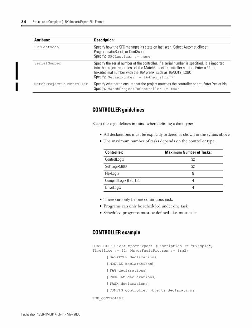
CONTROLLER guidelines
Keep these guidelines in mind when defining a data type:
• All declarations must be explicitly ordered as shown in the syntax above.• The maximum number of tasks depends on the controller type:
• There can only be one continuous task.• Programs can only be scheduled under one task• Scheduled programs must be defined - i.e. must exist
CONTROLLER example
CONTROLLER TestImportExport (Description := �Example", TimeSlice := 11, MajorFaultProgram := Prg2)
[DATATYPE declarations]
[MODULE declarations]
[TAG declarations]
[PROGRAM declarations]
[TASK declarations]
[CONFIG controller objects declarations]
END_CONTROLLER
SFCLastScan Specify how the SFC manages its state on last scan. Select AutomaticReset, ProgrammaticReset, or DontScan.Specify: SFCLastScan := name
SerialNumber Specify the serial number of the controller. If a serial number is specified, it is imported into the project regardless of the MatchProjectToController setting. Enter a 32-bit, hexadecimal number with the 16# prefix, such as 16#0012_E2BCSpecify: SerialNumber := 16#hex_string
MatchProjectToController Specify whether to ensure that the project matches the controller or not. Enter Yes or No.Specify: MatchProjectToController := text
Attribute: Description:
Controller: Maximum Number of Tasks:
ControlLogix 32
SoftLogix5800 32
FlexLogix 8
CompactLogix (L20, L30) 4
DriveLogix 4
Publication 1756-RM084K-EN-P - May 2005
Chapter 3
Create a Complete Import/Export File
Introduction This chapter explains how to enter project and configuration information in a complete import/export file.
For information on entering logic, see the next chapter.
Define a Data Type A DATATYPE component follows this structure:
DATATYPE <DataType_name> [(Attributes)]
[member_definition]
END_DATATYPE
Where:
For information about: See page:
Define a data type 3-1
Define a module 3-5
Define a tag 3-12
Define a program 3-29
Define a task 3-33
Define a trend 3-35
Define a controller 3-43
Item: Identifies:
DataType_name the data structure
Attributes attributes of the data structurecan also contain a description of the componentenclose in parenthesisseparate each attribute with a comma (,)
member_definition each member of the data structure
1 Publication 1756-RM084K-EN-P - May 2005
3-2 Create a Complete Import/Export File
Specify DATATYPE attributes
Specify these attributes for a DATATYPE:
Specify a DATATYPE member
There are two kinds of data type members. A bit member is a member in which only a single bit of information is to be accessed. A non-bit member is a member that is defined as another data type (such as SINT, INT, DINT, COUNTER, etc.).
A non-bit member definition follows this structure:
<TypeName> <MemberName> [(Attributes)];
All data types are allocated in 8-bit boundaries. A single bit of storage is not allowed, so a member cannot be a BOOL data type. To access a single bit, use the BIT declaration. BIT allows access to a single bit within a host member (a non-bit member).
A bit member uses the following syntax:
BIT <BitName> <HostMemberName> : <BitPosition> [(Attributes)];
Attribute: Description:
Description Provide information about the data type.Specify: Description := �text�
FamilyType Specify StringFamily for a string datatype. Specify NoFamily for all other datatypes.Specify: FamilyType := text
Publication 1756-RM084K-EN-P - May 2005
Create a Complete Import/Export File 3-3
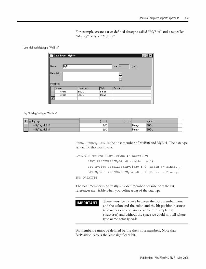
For example, create a user-defined datatype called �MyBits� and a tag called �MyTag� of type �MyBits.�
ZZZZZZZZZZMyBits0 is the host member of MyBit0 and MyBit1. The datatype syntax for this example is:
DATATYPE MyBits (FamilyType := NoFamily)
SINT ZZZZZZZZZZMyBits0 (Hidden := 1);
BIT MyBit0 ZZZZZZZZZZMyBits0 : 0 (Radix := Binary);
BIT MyBit1 ZZZZZZZZZZMyBits0 : 1 (Radix := Binary;
END_DATATYPE
The host member is normally a hidden member because only the bit references are visible when you define a tag of the datatype.
Bit members cannot be defined before their host members. Note that BitPosition zero is the least significant bit.
User-defined datatype “MyBits”
Tag “MyTag” of type “MyBits”
IMPORTANT There must be a space between the host member name and the colon and the colon and the bit position because type names can contain a colon (for example, I/O structures) and without the space we could not tell where type name actually ends.
Publication 1756-RM084K-EN-P - May 2005
3-4 Create a Complete Import/Export File
Specify DATATYPE member attributes
Specify these attributes for a member of a DATATYPE:
DATATYPE guidelines
Keep these guidelines in mind when defining a data type:
• Data types must be defined first within the controller body.
• Data types can be defined out of order. For example, if Type1 depends on Type2, Type2 can be defined first.
• Data types can be unverified. For example if Type1 depends on Type2 and Type2 is never defined, then Type1 will be accessible as an unverified type. Type2 will be typeless type. Tags of Type1 may be created but not of Type2.
• Data type members can be arrays but only one dimension is allowed.
• The following data types cannot be used in a user-defined data type: AXIS types, MOTION_GROUP, and MESSAGE.
DATATYPE example
DATATYPE MyStructure (FamilyType := NoFamily)
DINT x;
TIMER y[3] (Radix := Decimal);
SINT MyFlags (Hidden :=1);
BIT aBit0 MyFlags : 0 (Radix := Binary);
BIT aBit1 MyFlags : 1 (Radix := Binary);
END_DATATYPE
Attribute: Description:
Description Provide information about the data type member.Specify: Description := �text�
Radix Specify decimal, hex, octal, binary, exponential, float, or ASCII.Specify: Radix := value
Hidden Make the member a hidden member of the structure.Specify: Hidden := 1
Publication 1756-RM084K-EN-P - May 2005
Create a Complete Import/Export File 3-5
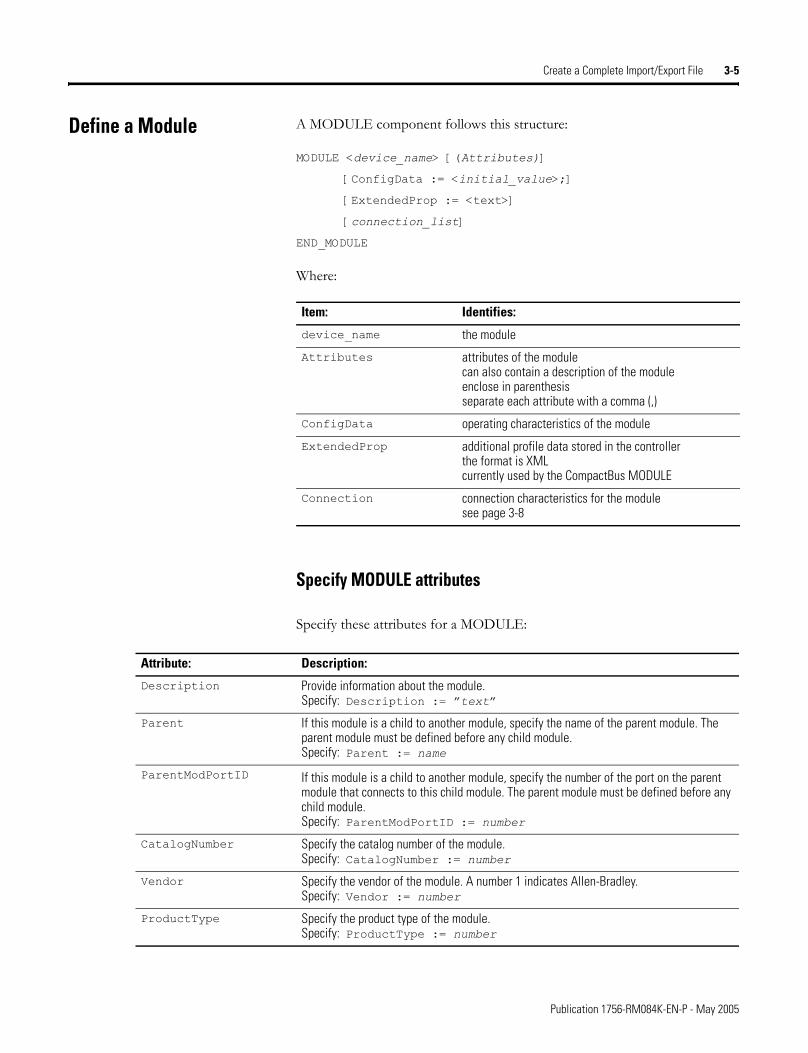
Define a Module A MODULE component follows this structure:
MODULE <device_name> [(Attributes)]
[ConfigData := <initial_value>;]
[ExtendedProp := <text>]
[connection_list]
END_MODULE
Where:
Specify MODULE attributes
Specify these attributes for a MODULE:
Item: Identifies:
device_name the module
Attributes attributes of the modulecan also contain a description of the moduleenclose in parenthesisseparate each attribute with a comma (,)
ConfigData operating characteristics of the module
ExtendedProp additional profile data stored in the controllerthe format is XMLcurrently used by the CompactBus MODULE
Connection connection characteristics for the modulesee page 3-8
Attribute: Description:
Description Provide information about the module.Specify: Description := �text�
Parent If this module is a child to another module, specify the name of the parent module. The parent module must be defined before any child module.Specify: Parent := name
ParentModPortID If this module is a child to another module, specify the number of the port on the parent module that connects to this child module. The parent module must be defined before any child module.Specify: ParentModPortID := number
CatalogNumber Specify the catalog number of the module.Specify: CatalogNumber := number
Vendor Specify the vendor of the module. A number 1 indicates Allen-Bradley.Specify: Vendor := number
ProductType Specify the product type of the module.Specify: ProductType := number
Publication 1756-RM084K-EN-P - May 2005
3-6 Create a Complete Import/Export File
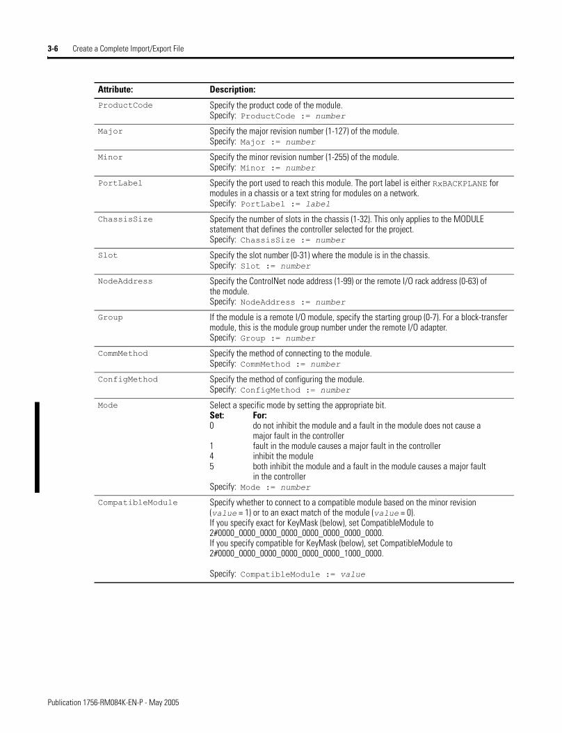
ProductCode Specify the product code of the module.Specify: ProductCode := number
Major Specify the major revision number (1-127) of the module.Specify: Major := number
Minor Specify the minor revision number (1-255) of the module.Specify: Minor := number
PortLabel Specify the port used to reach this module. The port label is either RxBACKPLANE for modules in a chassis or a text string for modules on a network.Specify: PortLabel := label
ChassisSize Specify the number of slots in the chassis (1-32). This only applies to the MODULE statement that defines the controller selected for the project.Specify: ChassisSize := number
Slot Specify the slot number (0-31) where the module is in the chassis.Specify: Slot := number
NodeAddress Specify the ControlNet node address (1-99) or the remote I/O rack address (0-63) of the module.Specify: NodeAddress := number
Group If the module is a remote I/O module, specify the starting group (0-7). For a block-transfer module, this is the module group number under the remote I/O adapter.Specify: Group := number
CommMethod Specify the method of connecting to the module. Specify: CommMethod := number
ConfigMethod Specify the method of configuring the module.Specify: ConfigMethod := number
Mode Select a specific mode by setting the appropriate bit.Set: For: 0 do not inhibit the module and a fault in the module does not cause a
major fault in the controller 1 fault in the module causes a major fault in the controller 4 inhibit the module 5 both inhibit the module and a fault in the module causes a major fault
in the controllerSpecify: Mode := number
CompatibleModule Specify whether to connect to a compatible module based on the minor revision (value = 1) or to an exact match of the module (value = 0).If you specify exact for KeyMask (below), set CompatibleModule to 2#0000_0000_0000_0000_0000_0000_0000_0000.If you specify compatible for KeyMask (below), set CompatibleModule to 2#0000_0000_0000_0000_0000_0000_1000_0000.
Specify: CompatibleModule := value
Attribute: Description:
Publication 1756-RM084K-EN-P - May 2005
Create a Complete Import/Export File 3-7
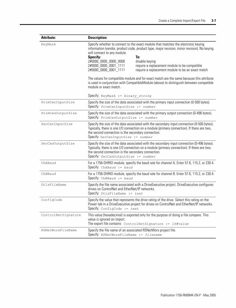
KeyMask Specify whether to connect to the exact module that matches the electronic keying information (vendor, product code, product type, major revision, minor revision). No keying will connect to any module.Specify: To: 2#0000_0000_0000_0000 disable keying 2#0000_0000_0001_1111 require a replacement module to be compatible 2#0000_0000_0001_1111 require a replacement module to be an exact match
The values for compatible module and for exact match are the same because this attribute is used in conjunction with CompatibleModule (above) to distinguish between compatible module or exact match.
Specify: KeyMask := binary_string
PrimCxnInputSize Specify the size of the data associated with the primary input connection (0-500 bytes). Specify: PrimCxnInputSize := number
PrimCxnOutputSize Specify the size of the data associated with the primary output connection (0-496 bytes).Specify: PrimCxnOutputSize := number
SecCxnInputSize Specify the size of the data associated with the secondary input connection (0-500 bytes). Typically, there is one I/O connection on a module (primary connection). If there are two, the second connection is the secondary connection.Specify: SecCxnInputSize := number
SecCxnOutputSize Specify the size of the data associated with the secondary input connection (0-496 bytes). Typically, there is one I/O connection on a module (primary connection). If there are two, the second connection is the secondary connection.Specify: SecCxnOutputSize := number
ChABaud For a 1756-DHRIO module, specify the baud rate for channel A. Enter 57.6, 115.2, or 230.4.Specify: ChABaud := baud
ChBBaud For a 1756-DHRIO module, specify the baud rate for channel B. Enter 57.6, 115.2, or 230.4.Specify: ChBBaud := baud
DtlsFileName Specify the file name associated with a DriveExecutive project. DriveExecutive configures drives on ControlNet and EtherNet/IP networks.Specify: DtlsFileName := text
ConfigCode Specify the value that represents the drive rating of the drive. Select this rating on the Power tab in a DriveExecutive project for drives on ControlNet and EtherNet/IP networks.Specify: ConfigCode := text
ControlNetSignature This value (hexadecimal) is exported only for the purpose of doing a file compare. This value is ignored on import.The export file contains: ControlNetSignature := 16#value
RSNetWorxFileName Specify the file name of an associated RSNetWorx project file.Specify: RSNetWorxFileName := filename
Attribute: Description:
Publication 1756-RM084K-EN-P - May 2005
3-8 Create a Complete Import/Export File
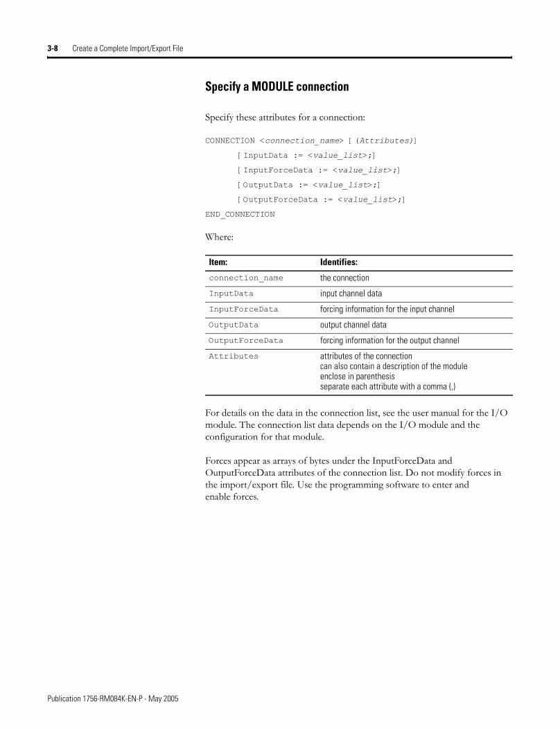
Specify a MODULE connection
Specify these attributes for a connection:
CONNECTION <connection_name> [(Attributes)]
[InputData := <value_list>;]
[InputForceData := <value_list>;]
[OutputData := <value_list>;]
[OutputForceData := <value_list>;]
END_CONNECTION
Where:
For details on the data in the connection list, see the user manual for the I/O module. The connection list data depends on the I/O module and the configuration for that module.
Forces appear as arrays of bytes under the InputForceData and OutputForceData attributes of the connection list. Do not modify forces in the import/export file. Use the programming software to enter and enable forces.
Item: Identifies:
connection_name the connection
InputData input channel data
InputForceData forcing information for the input channel
OutputData output channel data
OutputForceData forcing information for the output channel
Attributes attributes of the connectioncan also contain a description of the moduleenclose in parenthesisseparate each attribute with a comma (,)
Publication 1756-RM084K-EN-P - May 2005
Create a Complete Import/Export File 3-9
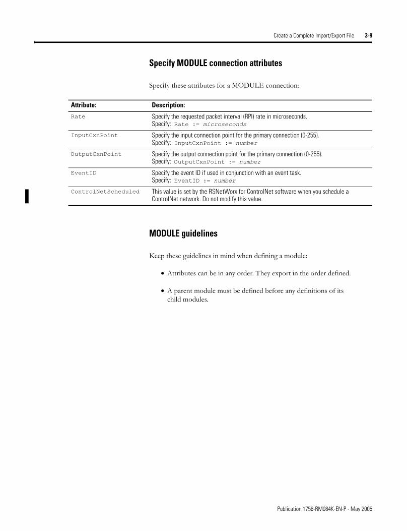
Specify MODULE connection attributes
Specify these attributes for a MODULE connection:
MODULE guidelines
Keep these guidelines in mind when defining a module:
• Attributes can be in any order. They export in the order defined.
• A parent module must be defined before any definitions of its child modules.
Attribute: Description:
Rate Specify the requested packet interval (RPI) rate in microseconds.Specify: Rate := microseconds
InputCxnPoint Specify the input connection point for the primary connection (0-255).Specify: InputCxnPoint := number
OutputCxnPoint Specify the output connection point for the primary connection (0-255).Specify: OutputCxnPoint := number
EventID Specify the event ID if used in conjunction with an event task.Specify: EventID := number
ControlNetScheduled This value is set by the RSNetWorx for ControlNet software when you schedule a ControlNet network. Do not modify this value.
Publication 1756-RM084K-EN-P - May 2005
3-10 Create a Complete Import/Export File
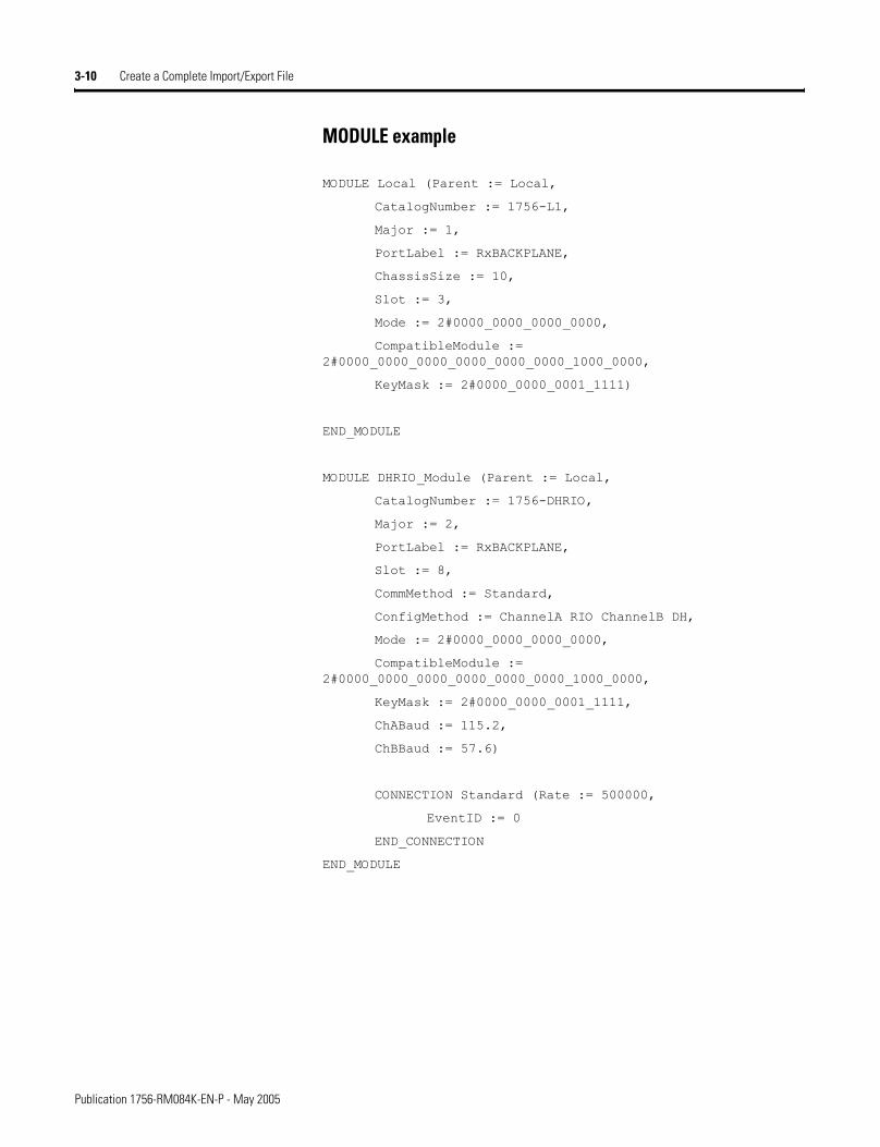
MODULE example
MODULE Local (Parent := Local,
CatalogNumber := 1756-L1,
Major := 1,
PortLabel := RxBACKPLANE,
ChassisSize := 10,
Slot := 3,
Mode := 2#0000_0000_0000_0000,
CompatibleModule := 2#0000_0000_0000_0000_0000_0000_1000_0000,
KeyMask := 2#0000_0000_0001_1111)
END_MODULE
MODULE DHRIO_Module (Parent := Local,
CatalogNumber := 1756-DHRIO,
Major := 2,
PortLabel := RxBACKPLANE,
Slot := 8,
CommMethod := Standard,
ConfigMethod := ChannelA RIO ChannelB DH,
Mode := 2#0000_0000_0000_0000,
CompatibleModule := 2#0000_0000_0000_0000_0000_0000_1000_0000,
KeyMask := 2#0000_0000_0001_1111,
ChABaud := 115.2,
ChBBaud := 57.6)
CONNECTION Standard (Rate := 500000,
EventID := 0
END_CONNECTION
END_MODULE
Publication 1756-RM084K-EN-P - May 2005
Create a Complete Import/Export File 3-11
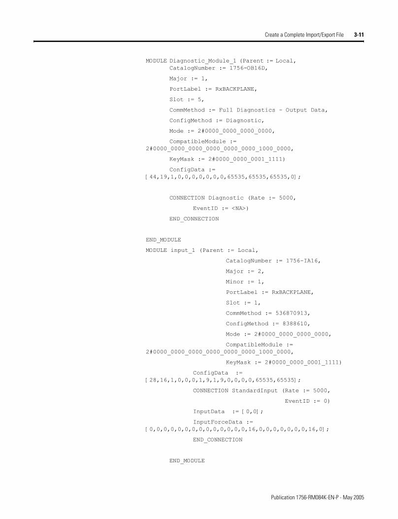
MODULE Diagnostic_Module_1 (Parent := Local, CatalogNumber := 1756-OB16D,
Major := 1,
PortLabel := RxBACKPLANE,
Slot := 5,
CommMethod := Full Diagnostics - Output Data,
ConfigMethod := Diagnostic,
Mode := 2#0000_0000_0000_0000,
CompatibleModule := 2#0000_0000_0000_0000_0000_0000_1000_0000,
KeyMask := 2#0000_0000_0001_1111)
ConfigData := [44,19,1,0,0,0,0,0,0,0,65535,65535,65535,0];
CONNECTION Diagnostic (Rate := 5000,
EventID := <NA>)
END_CONNECTION
END_MODULE
MODULE input_1 (Parent := Local,
CatalogNumber := 1756-IA16,
Major := 2,
Minor := 1,
PortLabel := RxBACKPLANE,
Slot := 1,
CommMethod := 536870913,
ConfigMethod := 8388610,
Mode := 2#0000_0000_0000_0000,
CompatibleModule := 2#0000_0000_0000_0000_0000_0000_1000_0000,
KeyMask := 2#0000_0000_0001_1111)
ConfigData := [28,16,1,0,0,0,1,9,1,9,0,0,0,0,65535,65535];
CONNECTION StandardInput (Rate := 5000,
EventID := 0)
InputData := [0,0];
InputForceData := [0,0,0,0,0,0,0,0,0,0,0,0,0,0,16,0,0,0,0,0,0,0,16,0];
END_CONNECTION
END_MODULE
Publication 1756-RM084K-EN-P - May 2005
3-12 Create a Complete Import/Export File
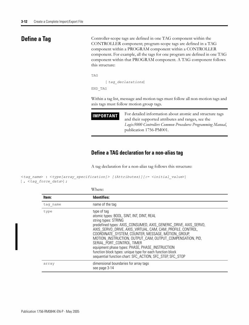
Define a Tag Controller-scope tags are defined in one TAG component within the CONTROLLER component; program-scope tags are defined in a TAG component within a PROGRAM component within a CONTROLLER component. For example, all the tags for one program are defined in one TAG component within that PROGRAM component. A TAG component follows this structure:
TAG
[tag_declarations]
END_TAG
Within a tag list, message and motion tags must follow all non-motion tags and axis tags must follow motion group tags.
Define a TAG declaration for a non-alias tag
A tag declaration for a non-alias tag follows this structure:
<tag_name> : <type[array_specification]> [(Attributes)][:= <initial_value>] [, <tag_force_data>];
Where:
IMPORTANT For detailed information about atomic and structure tags and their supported attributes and ranges, see the Logix5000 Controllers Common Procedures Programming Manual, publication 1756-PM001.
Item: Identifies:
tag_name name of the tag
type type of tagatomic types: BOOL, SINT, INT, DINT, REALstring types: STRINGpredefined types: AXIS_CONSUMED, AXIS_GENERIC_DRIVE, AXIS_SERVO, AXIS_SERVO_DRIVE, AXIS_VIRTUAL, CAM, CAM_PROFILE, CONTROL, COORDINATE_SYSTEM, COUNTER, MESSAGE, MOTION_GROUP, MOTION_INSTRUCTION, OUTPUT_CAM, OUTPUT_COMPENSATION, PID, SERIAL_PORT_CONTROL, TIMERequipment phase types: PHASE, PHASE_INSTRUCTIONfunction block types: unique type for each function blocksequential function chart: SFC_ACTION, SFC_STEP, SFC_STOP
array dimensional boundaries for array tagssee page 3-14
Publication 1756-RM084K-EN-P - May 2005
Create a Complete Import/Export File 3-13
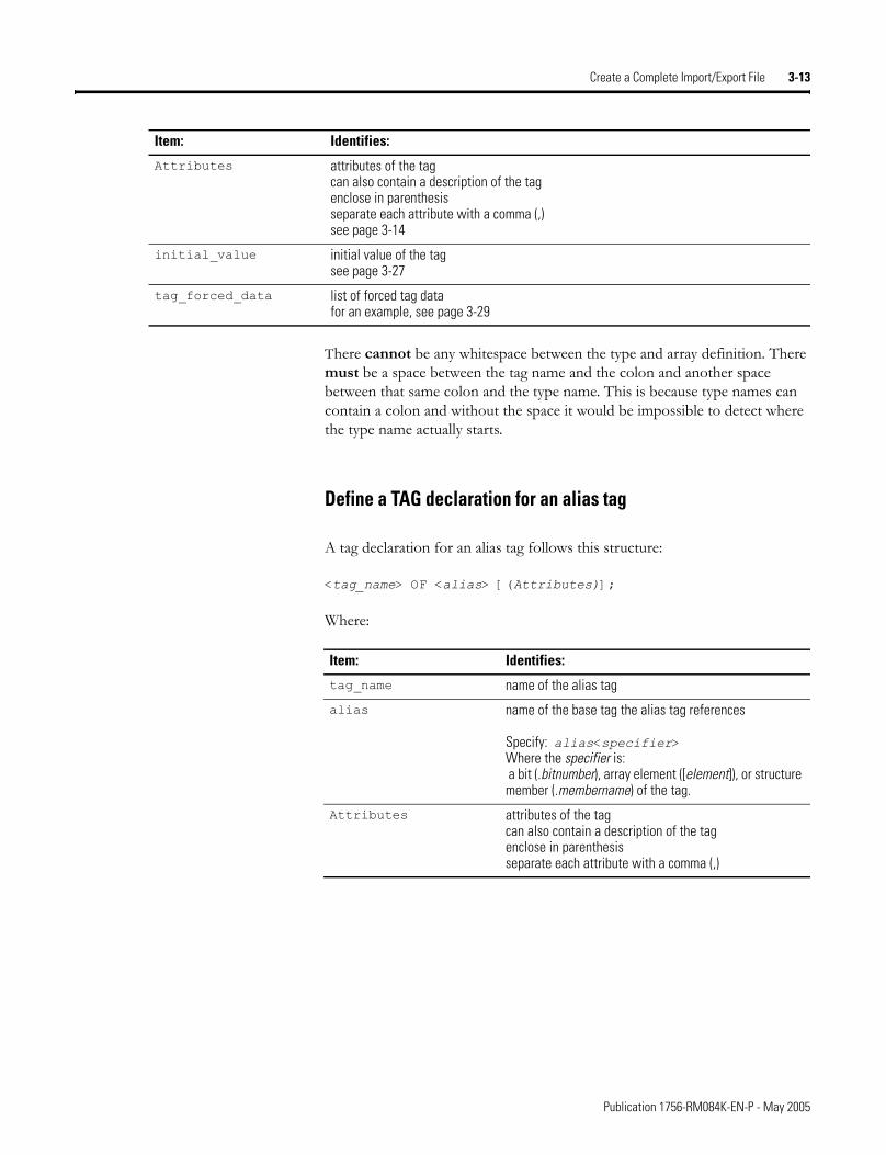
There cannot be any whitespace between the type and array definition. There must be a space between the tag name and the colon and another space between that same colon and the type name. This is because type names can contain a colon and without the space it would be impossible to detect where the type name actually starts.
Define a TAG declaration for an alias tag
A tag declaration for an alias tag follows this structure:
<tag_name> OF <alias> [(Attributes)];
Where:
Attributes attributes of the tagcan also contain a description of the tagenclose in parenthesisseparate each attribute with a comma (,)see page 3-14
initial_value initial value of the tagsee page 3-27
tag_forced_data list of forced tag datafor an example, see page 3-29
Item: Identifies:
Item: Identifies:
tag_name name of the alias tag
alias name of the base tag the alias tag references
Specify: alias<specifier>Where the specifier is: a bit (.bitnumber), array element ([element]), or structure member (.membername) of the tag.
Attributes attributes of the tagcan also contain a description of the tagenclose in parenthesisseparate each attribute with a comma (,)
Publication 1756-RM084K-EN-P - May 2005
3-14 Create a Complete Import/Export File
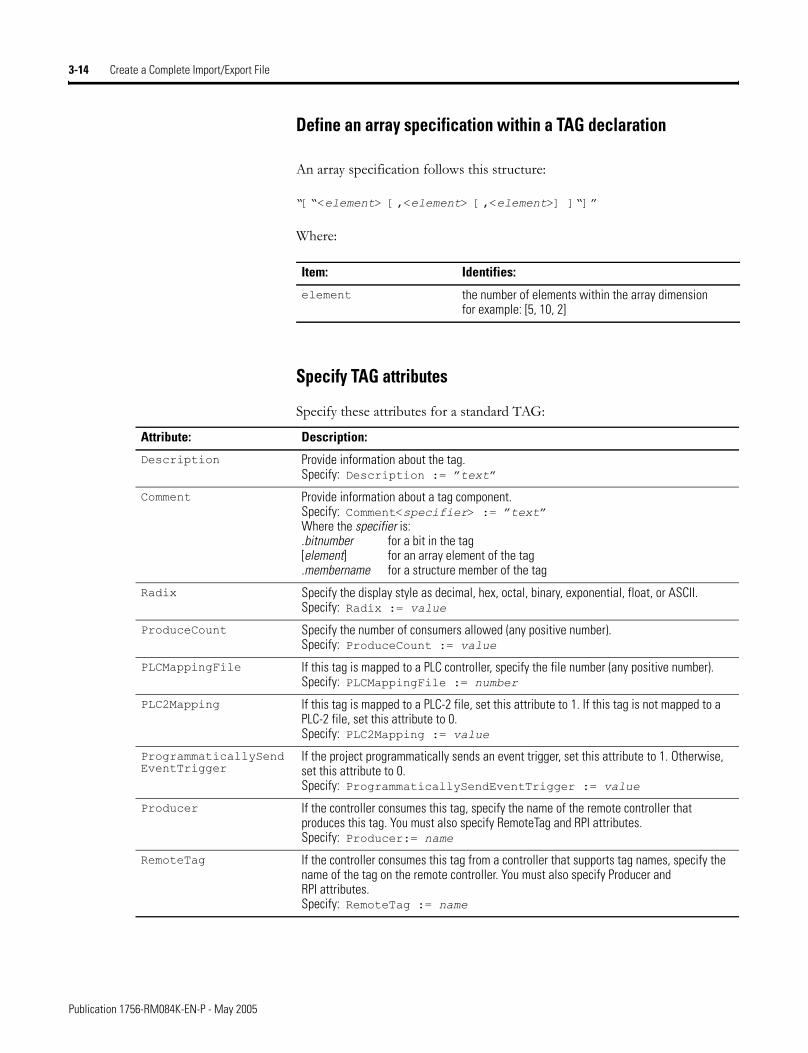
Define an array specification within a TAG declaration
An array specification follows this structure:
�[�<element> [,<element> [,<element>] ]�]�
Where:
Specify TAG attributes
Specify these attributes for a standard TAG:
Item: Identifies:
element the number of elements within the array dimensionfor example: [5, 10, 2]
Attribute: Description:
Description Provide information about the tag.Specify: Description := �text�
Comment Provide information about a tag component.Specify: Comment<specifier> := �text�Where the specifier is:.bitnumber for a bit in the tag[element] for an array element of the tag .membername for a structure member of the tag
Radix Specify the display style as decimal, hex, octal, binary, exponential, float, or ASCII.Specify: Radix := value
ProduceCount Specify the number of consumers allowed (any positive number).Specify: ProduceCount := value
PLCMappingFile If this tag is mapped to a PLC controller, specify the file number (any positive number).Specify: PLCMappingFile := number
PLC2Mapping If this tag is mapped to a PLC-2 file, set this attribute to 1. If this tag is not mapped to a PLC-2 file, set this attribute to 0.Specify: PLC2Mapping := value
ProgrammaticallySend EventTrigger
If the project programmatically sends an event trigger, set this attribute to 1. Otherwise, set this attribute to 0.Specify: ProgrammaticallySendEventTrigger := value
Producer If the controller consumes this tag, specify the name of the remote controller that produces this tag. You must also specify RemoteTag and RPI attributes.Specify: Producer:= name
RemoteTag If the controller consumes this tag from a controller that supports tag names, specify the name of the tag on the remote controller. You must also specify Producer and RPI attributes.Specify: RemoteTag := name
Publication 1756-RM084K-EN-P - May 2005
Create a Complete Import/Export File 3-15
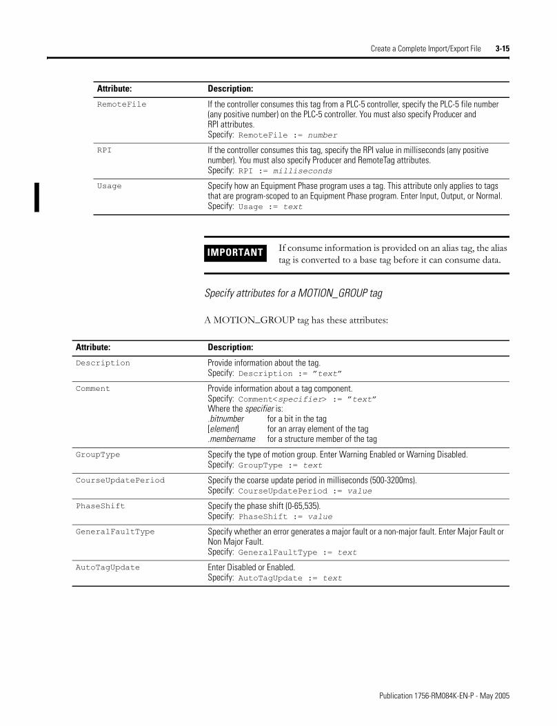
Specify attributes for a MOTION_GROUP tag
A MOTION_GROUP tag has these attributes:
RemoteFile If the controller consumes this tag from a PLC-5 controller, specify the PLC-5 file number (any positive number) on the PLC-5 controller. You must also specify Producer and RPI attributes.Specify: RemoteFile := number
RPI If the controller consumes this tag, specify the RPI value in milliseconds (any positive number). You must also specify Producer and RemoteTag attributes.Specify: RPI := milliseconds
Usage Specify how an Equipment Phase program uses a tag. This attribute only applies to tags that are program-scoped to an Equipment Phase program. Enter Input, Output, or Normal.Specify: Usage := text
Attribute: Description:
IMPORTANT If consume information is provided on an alias tag, the alias tag is converted to a base tag before it can consume data.
Attribute: Description:
Description Provide information about the tag.Specify: Description := �text�
Comment Provide information about a tag component.Specify: Comment<specifier> := �text�Where the specifier is:.bitnumber for a bit in the tag[element] for an array element of the tag .membername for a structure member of the tag
GroupType Specify the type of motion group. Enter Warning Enabled or Warning Disabled.Specify: GroupType := text
CourseUpdatePeriod Specify the coarse update period in milliseconds (500-3200ms).Specify: CourseUpdatePeriod := value
PhaseShift Specify the phase shift (0-65,535).Specify: PhaseShift := value
GeneralFaultType Specify whether an error generates a major fault or a non-major fault. Enter Major Fault or Non Major Fault.Specify: GeneralFaultType := text
AutoTagUpdate Enter Disabled or Enabled.Specify: AutoTagUpdate := text
Publication 1756-RM084K-EN-P - May 2005
3-16 Create a Complete Import/Export File
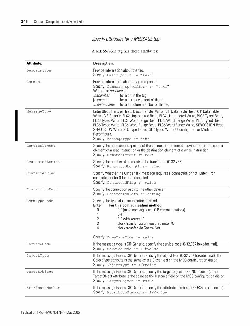
Specify attributes for a MESSAGE tag
A MESSAGE tag has these attributes:
Attribute: Description:
Description Provide information about the tag.Specify: Description := �text�
Comment Provide information about a tag component.Specify: Comment<specifier> := �text�Where the specifier is:.bitnumber for a bit in the tag[element] for an array element of the tag .membername for a structure member of the tag
MessageType Enter Block Transfer Read, Block Transfer Write, CIP Data Table Read, CIP Data Table Write, CIP Generic, PLC2 Unprotected Read, PLC2 Unprotected Write, PLC3 Typed Read, PLC3 Typed Write, PLC3 Word Range Read, PLC3 Word Range Write, PLC5 Typed Read, PLC5 Typed Write, PLC5 Word Range Read, PLC5 Word Range Write, SERCOS IDN Read, SERCOS IDN Write, SLC Typed Read, SLC Typed Write, Unconfigured, or Module Reconfigure.Specify: MessageType := text
RemoteElement Specify the address or tag name of the element in the remote device. This is the source element of a read instruction or the destination element of a write instruction.Specify: RemoteElement := text
RequestedLength Specify the number of elements to be transferred (0-32,767).Specify: RequestedLength := value
ConnectedFlag Specify whether the CIP generic message requires a connection or not. Enter 1 for connected; enter 0 for not connected.Specify: ConnectedFlag := value
ConnectionPath Specify the connection path to the other device.Specify: ConnectionPath := string
CommTypeCode Specify the type of communication method.Enter For this communication method
0 CIP (most messages use CIP communications) 1 DH+ 2 CIP with source ID 3 block transfer via universal remote I/O 4 block transfer via ControlNet
Specify: CommTypeCode := value
ServiceCode If the message type is CIP Generic, specify the service code (0-32,767 hexadecimal).Specify: ServiceCode := 16#value
ObjectType If the message type is CIP Generic, specify the object type (0-32,767 hexadecimal). The ObjectType attribute is the same as the Class field on the MSG configuration dialog.Specify: ObjectType := 16#value
TargetObject If the message type is CIP Generic, specify the target object (0-32,767 decimal). The TargetObject attribute is the same as the Instance field on the MSG configuration dialog.Specify: TargetObject := value
AttributeNumber If the message type is CIP Generic, specify the attribute number (0-65,535 hexadecimal).Specify: AttributeNumber := 16#value
Publication 1756-RM084K-EN-P - May 2005
Create a Complete Import/Export File 3-17
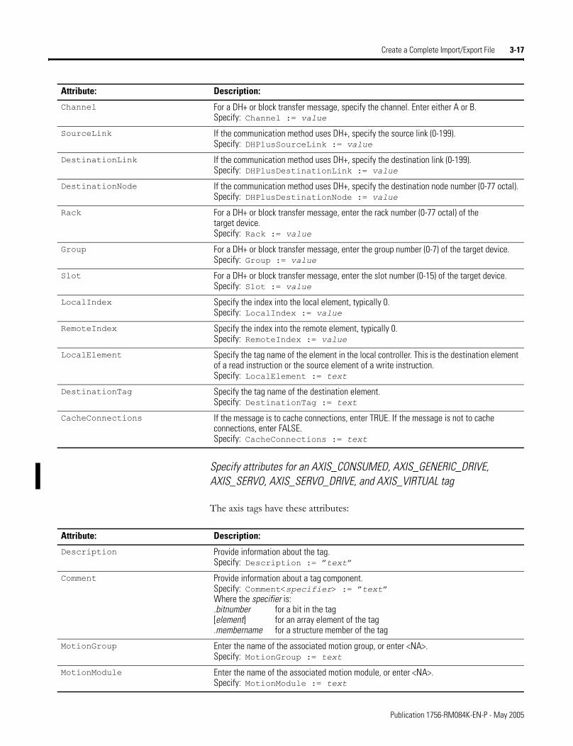
Specify attributes for an AXIS_CONSUMED, AXIS_GENERIC_DRIVE, AXIS_SERVO, AXIS_SERVO_DRIVE, and AXIS_VIRTUAL tag
The axis tags have these attributes:
Channel For a DH+ or block transfer message, specify the channel. Enter either A or B.Specify: Channel := value
SourceLink If the communication method uses DH+, specify the source link (0-199).Specify: DHPlusSourceLink := value
DestinationLink If the communication method uses DH+, specify the destination link (0-199).Specify: DHPlusDestinationLink := value
DestinationNode If the communication method uses DH+, specify the destination node number (0-77 octal).Specify: DHPlusDestinationNode := value
Rack For a DH+ or block transfer message, enter the rack number (0-77 octal) of the target device.Specify: Rack := value
Group For a DH+ or block transfer message, enter the group number (0-7) of the target device.Specify: Group := value
Slot For a DH+ or block transfer message, enter the slot number (0-15) of the target device.Specify: Slot := value
LocalIndex Specify the index into the local element, typically 0.Specify: LocalIndex := value
RemoteIndex Specify the index into the remote element, typically 0.Specify: RemoteIndex := value
LocalElement Specify the tag name of the element in the local controller. This is the destination element of a read instruction or the source element of a write instruction.Specify: LocalElement := text
DestinationTag Specify the tag name of the destination element.Specify: DestinationTag := text
CacheConnections If the message is to cache connections, enter TRUE. If the message is not to cache connections, enter FALSE.Specify: CacheConnections := text
Attribute: Description:
Attribute: Description:
Description Provide information about the tag.Specify: Description := �text�
Comment Provide information about a tag component.Specify: Comment<specifier> := �text�Where the specifier is:.bitnumber for a bit in the tag[element] for an array element of the tag .membername for a structure member of the tag
MotionGroup Enter the name of the associated motion group, or enter <NA>.Specify: MotionGroup := text
MotionModule Enter the name of the associated motion module, or enter <NA>.Specify: MotionModule := text
Publication 1756-RM084K-EN-P - May 2005
3-18 Create a Complete Import/Export File
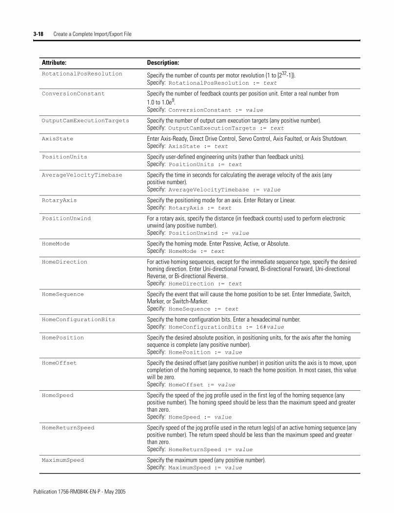
RotationalPosResolution Specify the number of counts per motor revolution (1 to [232-1]).Specify: RotationalPosResolution := text
ConversionConstant Specify the number of feedback counts per position unit. Enter a real number from 1.0 to 1.0e9.Specify: ConversionConstant := value
OutputCamExecutionTargets Specify the number of output cam execution targets (any positive number).Specify: OutputCamExecutionTargets := text
AxisState Enter Axis-Ready, Direct Drive Control, Servo Control, Axis Faulted, or Axis Shutdown.Specify: AxisState := text
PositionUnits Specify user-defined engineering units (rather than feedback units).Specify: PositionUnits := text
AverageVelocityTimebase Specify the time in seconds for calculating the average velocity of the axis (any positive number).Specify: AverageVelocityTimebase := value
RotaryAxis Specify the positioning mode for an axis. Enter Rotary or Linear.Specify: RotaryAxis := text
PositionUnwind For a rotary axis, specify the distance (in feedback counts) used to perform electronic unwind (any positive number).Specify: PositionUnwind := value
HomeMode Specify the homing mode. Enter Passive, Active, or Absolute.Specify: HomeMode := text
HomeDirection For active homing sequences, except for the immediate sequence type, specify the desired homing direction. Enter Uni-directional Forward, Bi-directional Forward, Uni-directional Reverse, or Bi-directional Reverse.Specify: HomeDirection := text
HomeSequence Specify the event that will cause the home position to be set. Enter Immediate, Switch, Marker, or Switch-Marker.Specify: HomeSequence := text
HomeConfigurationBits Specify the home configuration bits. Enter a hexadecimal number.Specify: HomeConfigurationBits := 16#value
HomePosition Specify the desired absolute position, in positioning units, for the axis after the homing sequence is complete (any positive number).Specify: HomePosition := value
HomeOffset Specify the desired offset (any positive number) in position units the axis is to move, upon completion of the homing sequence, to reach the home position. In most cases, this value will be zero.Specify: HomeOffset := value
HomeSpeed Specify the speed of the jog profile used in the first leg of the homing sequence (any positive number). The homing speed should be less than the maximum speed and greater than zero.Specify: HomeSpeed := value
HomeReturnSpeed Specify speed of the jog profile used in the return leg(s) of an active homing sequence (any positive number). The return speed should be less than the maximum speed and greater than zero.Specify: HomeReturnSpeed := value
MaximumSpeed Specify the maximum speed (any positive number).Specify: MaximumSpeed := value
Attribute: Description:
Publication 1756-RM084K-EN-P - May 2005
Create a Complete Import/Export File 3-19
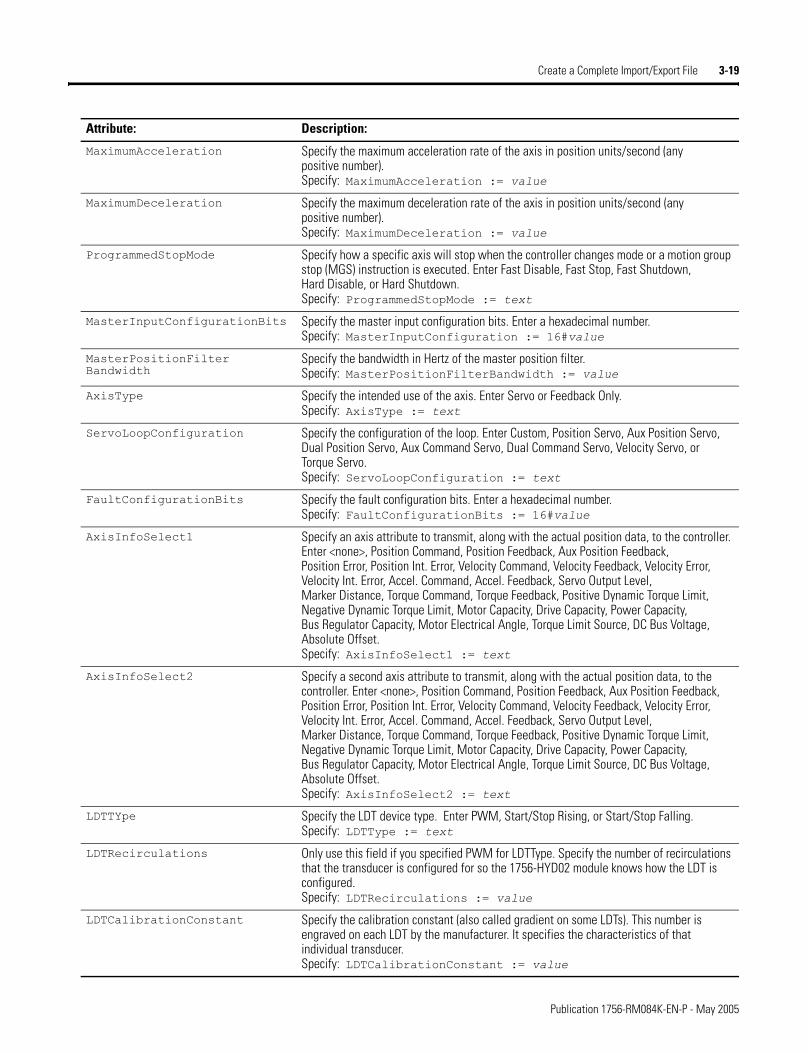
MaximumAcceleration Specify the maximum acceleration rate of the axis in position units/second (any positive number).Specify: MaximumAcceleration := value
MaximumDeceleration Specify the maximum deceleration rate of the axis in position units/second (any positive number).Specify: MaximumDeceleration := value
ProgrammedStopMode Specify how a specific axis will stop when the controller changes mode or a motion group stop (MGS) instruction is executed. Enter Fast Disable, Fast Stop, Fast Shutdown, Hard Disable, or Hard Shutdown.Specify: ProgrammedStopMode := text
MasterInputConfigurationBits Specify the master input configuration bits. Enter a hexadecimal number.Specify: MasterInputConfiguration := 16#value
MasterPositionFilter Bandwidth
Specify the bandwidth in Hertz of the master position filter. Specify: MasterPositionFilterBandwidth := value
AxisType Specify the intended use of the axis. Enter Servo or Feedback Only. Specify: AxisType := text
ServoLoopConfiguration Specify the configuration of the loop. Enter Custom, Position Servo, Aux Position Servo, Dual Position Servo, Aux Command Servo, Dual Command Servo, Velocity Servo, or Torque Servo.Specify: ServoLoopConfiguration := text
FaultConfigurationBits Specify the fault configuration bits. Enter a hexadecimal number.Specify: FaultConfigurationBits := 16#value
AxisInfoSelect1 Specify an axis attribute to transmit, along with the actual position data, to the controller. Enter <none>, Position Command, Position Feedback, Aux Position Feedback, Position Error, Position Int. Error, Velocity Command, Velocity Feedback, Velocity Error, Velocity Int. Error, Accel. Command, Accel. Feedback, Servo Output Level, Marker Distance, Torque Command, Torque Feedback, Positive Dynamic Torque Limit, Negative Dynamic Torque Limit, Motor Capacity, Drive Capacity, Power Capacity, Bus Regulator Capacity, Motor Electrical Angle, Torque Limit Source, DC Bus Voltage, Absolute Offset.Specify: AxisInfoSelect1 := text
AxisInfoSelect2 Specify a second axis attribute to transmit, along with the actual position data, to the controller. Enter <none>, Position Command, Position Feedback, Aux Position Feedback, Position Error, Position Int. Error, Velocity Command, Velocity Feedback, Velocity Error, Velocity Int. Error, Accel. Command, Accel. Feedback, Servo Output Level, Marker Distance, Torque Command, Torque Feedback, Positive Dynamic Torque Limit, Negative Dynamic Torque Limit, Motor Capacity, Drive Capacity, Power Capacity, Bus Regulator Capacity, Motor Electrical Angle, Torque Limit Source, DC Bus Voltage, Absolute Offset.Specify: AxisInfoSelect2 := text
LDTTYpe Specify the LDT device type. Enter PWM, Start/Stop Rising, or Start/Stop Falling.Specify: LDTType := text
LDTRecirculations Only use this field if you specified PWM for LDTType. Specify the number of recirculations that the transducer is configured for so the 1756-HYD02 module knows how the LDT is configured.Specify: LDTRecirculations := value
LDTCalibrationConstant Specify the calibration constant (also called gradient on some LDTs). This number is engraved on each LDT by the manufacturer. It specifies the characteristics of that individual transducer.Specify: LDTCalibrationConstant := value
Attribute: Description:
Publication 1756-RM084K-EN-P - May 2005
3-20 Create a Complete Import/Export File
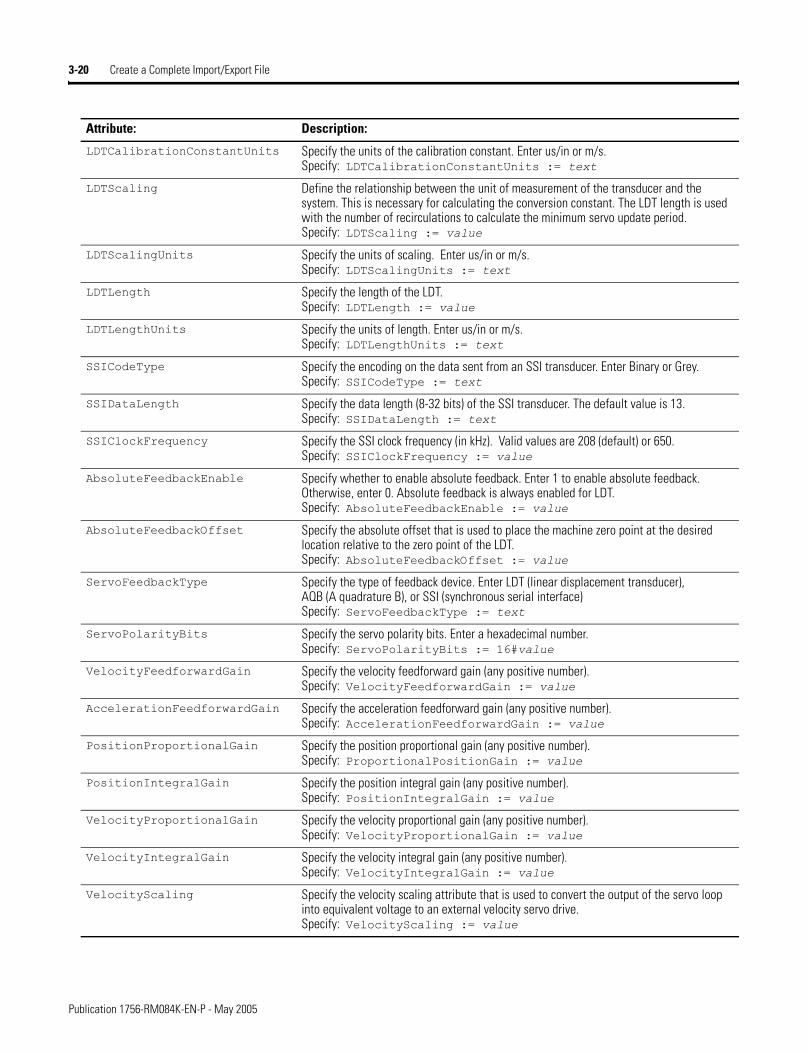
LDTCalibrationConstantUnits Specify the units of the calibration constant. Enter us/in or m/s.Specify: LDTCalibrationConstantUnits := text
LDTScaling Define the relationship between the unit of measurement of the transducer and the system. This is necessary for calculating the conversion constant. The LDT length is used with the number of recirculations to calculate the minimum servo update period.Specify: LDTScaling := value
LDTScalingUnits Specify the units of scaling. Enter us/in or m/s.Specify: LDTScalingUnits := text
LDTLength Specify the length of the LDT.Specify: LDTLength := value
LDTLengthUnits Specify the units of length. Enter us/in or m/s.Specify: LDTLengthUnits := text
SSICodeType Specify the encoding on the data sent from an SSI transducer. Enter Binary or Grey.Specify: SSICodeType := text
SSIDataLength Specify the data length (8-32 bits) of the SSI transducer. The default value is 13.Specify: SSIDataLength := text
SSIClockFrequency Specify the SSI clock frequency (in kHz). Valid values are 208 (default) or 650.Specify: SSIClockFrequency := value
AbsoluteFeedbackEnable Specify whether to enable absolute feedback. Enter 1 to enable absolute feedback. Otherwise, enter 0. Absolute feedback is always enabled for LDT.Specify: AbsoluteFeedbackEnable := value
AbsoluteFeedbackOffset Specify the absolute offset that is used to place the machine zero point at the desired location relative to the zero point of the LDT.Specify: AbsoluteFeedbackOffset := value
ServoFeedbackType Specify the type of feedback device. Enter LDT (linear displacement transducer), AQB (A quadrature B), or SSI (synchronous serial interface)Specify: ServoFeedbackType := text
ServoPolarityBits Specify the servo polarity bits. Enter a hexadecimal number.Specify: ServoPolarityBits := 16#value
VelocityFeedforwardGain Specify the velocity feedforward gain (any positive number).Specify: VelocityFeedforwardGain := value
AccelerationFeedforwardGain Specify the acceleration feedforward gain (any positive number).Specify: AccelerationFeedforwardGain := value
PositionProportionalGain Specify the position proportional gain (any positive number).Specify: ProportionalPositionGain := value
PositionIntegralGain Specify the position integral gain (any positive number).Specify: PositionIntegralGain := value
VelocityProportionalGain Specify the velocity proportional gain (any positive number).Specify: VelocityProportionalGain := value
VelocityIntegralGain Specify the velocity integral gain (any positive number).Specify: VelocityIntegralGain := value
VelocityScaling Specify the velocity scaling attribute that is used to convert the output of the servo loop into equivalent voltage to an external velocity servo drive.Specify: VelocityScaling := value
Attribute: Description:
Publication 1756-RM084K-EN-P - May 2005
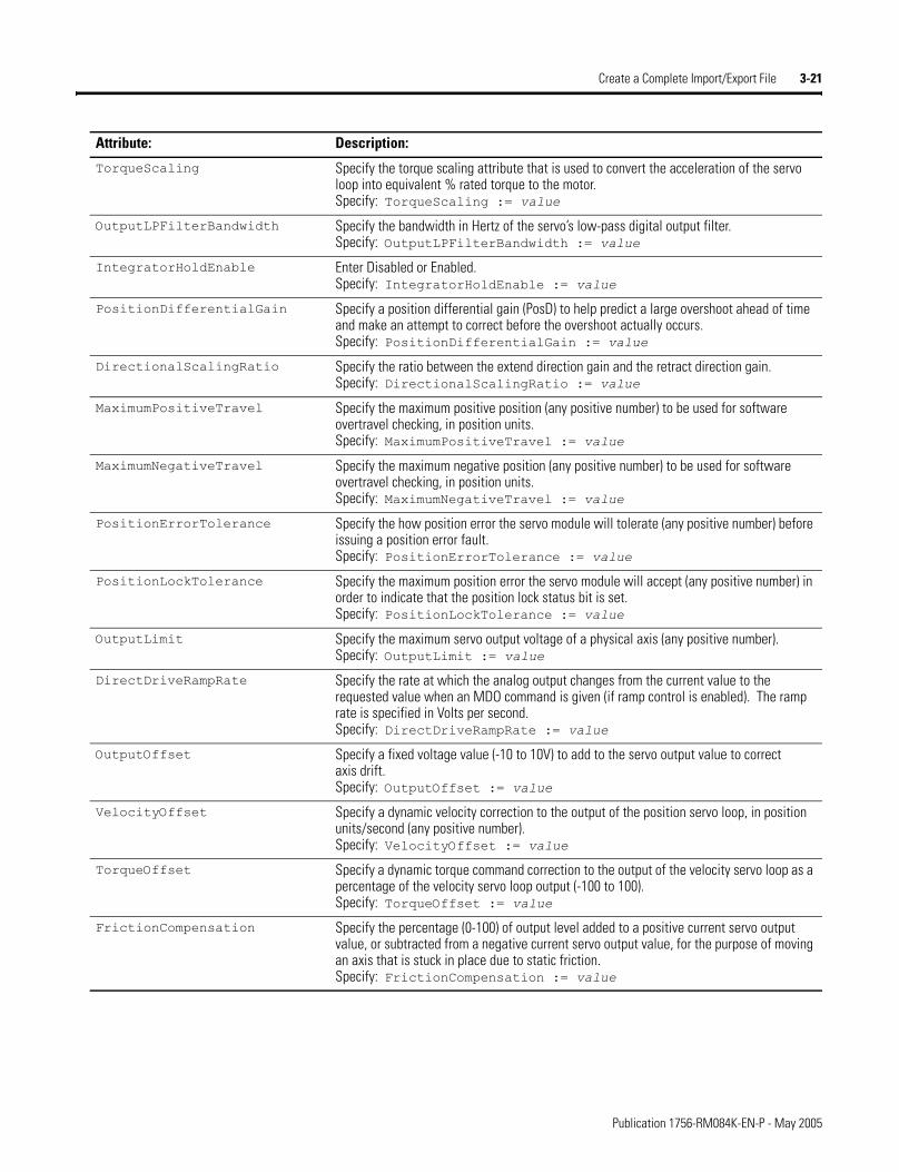
Create a Complete Import/Export File 3-21
TorqueScaling Specify the torque scaling attribute that is used to convert the acceleration of the servo loop into equivalent % rated torque to the motor.Specify: TorqueScaling := value
OutputLPFilterBandwidth Specify the bandwidth in Hertz of the servo’s low-pass digital output filter.Specify: OutputLPFilterBandwidth := value
IntegratorHoldEnable Enter Disabled or Enabled.Specify: IntegratorHoldEnable := value
PositionDifferentialGain Specify a position differential gain (PosD) to help predict a large overshoot ahead of time and make an attempt to correct before the overshoot actually occurs.Specify: PositionDifferentialGain := value
DirectionalScalingRatio Specify the ratio between the extend direction gain and the retract direction gain.Specify: DirectionalScalingRatio := value
MaximumPositiveTravel Specify the maximum positive position (any positive number) to be used for software overtravel checking, in position units.Specify: MaximumPositiveTravel := value
MaximumNegativeTravel Specify the maximum negative position (any positive number) to be used for software overtravel checking, in position units.Specify: MaximumNegativeTravel := value
PositionErrorTolerance Specify the how position error the servo module will tolerate (any positive number) before issuing a position error fault.Specify: PositionErrorTolerance := value
PositionLockTolerance Specify the maximum position error the servo module will accept (any positive number) in order to indicate that the position lock status bit is set.Specify: PositionLockTolerance := value
OutputLimit Specify the maximum servo output voltage of a physical axis (any positive number).Specify: OutputLimit := value
DirectDriveRampRate Specify the rate at which the analog output changes from the current value to the requested value when an MDO command is given (if ramp control is enabled). The ramp rate is specified in Volts per second.Specify: DirectDriveRampRate := value
OutputOffset Specify a fixed voltage value (-10 to 10V) to add to the servo output value to correct axis drift.Specify: OutputOffset := value
VelocityOffset Specify a dynamic velocity correction to the output of the position servo loop, in position units/second (any positive number).Specify: VelocityOffset := value
TorqueOffset Specify a dynamic torque command correction to the output of the velocity servo loop as a percentage of the velocity servo loop output (-100 to 100).Specify: TorqueOffset := value
FrictionCompensation Specify the percentage (0-100) of output level added to a positive current servo output value, or subtracted from a negative current servo output value, for the purpose of moving an axis that is stuck in place due to static friction.Specify: FrictionCompensation := value
Attribute: Description:
Publication 1756-RM084K-EN-P - May 2005
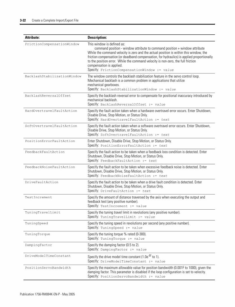
3-22 Create a Complete Import/Export File
FrictionCompensationWindow This window is defined as: command position - window attribute to command position + window attribute
While the command velocity is zero and the actual position is within this window, the friction compensation (or deadband compensation, for hydraulics) is applied proportionally to the position error. While the command velocity is non-zero, the full friction compensation is applied.Specify: FrictionCompensationWindow := value
BacklashStabilizationWindow The window controls the backlash stabilization feature in the servo control loop. Mechanical backlash is a common problem in applications that utilize mechanical gearboxes. Specify: BacklashStabilizationWindow := value
BacklashReversalOffset Specify the backlash reversal error to compensate for positional inaccuracy introduced by mechanical backlash.Specify: BacklashReversalOffset := value
HardOvertravelFaultAction Specify the fault action taken when a hardware overtravel error occurs. Enter Shutdown, Disable Drive, Stop Motion, or Status Only. Specify: HardOvertravelFaultAction := text
SoftOvertravelFaultAction Specify the fault action taken when a software overtravel error occurs. Enter Shutdown, Disable Drive, Stop Motion, or Status Only.Specify: SoftOvertravelFaultAction := text
PositionErrorFaultAction Enter Shutdown, Disable Drive, Stop Motion, or Status Only.Specify: PositionErrorFaultAction := text
FeedbackFaultAction Specify the fault action to be taken when a feedback loss condition is detected. Enter Shutdown, Disable Drive, Stop Motion, or Status Only.Specify: FeedbackFaultAction := text
FeedbackNoiseFaultAction Specify the fault action to be taken when excessive feedback noise is detected. Enter Shutdown, Disable Drive, Stop Motion, or Status Only.Specify: FeedbackNoiseFaultAction := text
DriveFaultAction Specify the fault action to be taken when a drive fault condition is detected. Enter Shutdown, Disable Drive, Stop Motion, or Status Only.Specify: DriveFaultAction := text
TestIncrement Specify the amount of distance traversed by the axis when executing the output and feedback test (any positive number).Specify: TestIncrement := value
TuningTravelLimit Specify the tuning travel limit in revolutions (any positive number).Specify: TuningTravelLimit := value
TuningSpeed Specify the tuning speed in revolutions per second (any positive number).Specify: TuningSpeed := value
TuningTorque Specify the tuning torque % rated (0-300).Specify: TuningTorque := value
DampingFactor Specify the damping factor (0.5 to 2).Specify: DampingFactor := value
DriveModelTimeConstant Specify the drive model time constant (1.0e-6f to 1).Specify: DriveModelTimeConstant := value
PositionServoBandwidth Specify the maximum allowable value for position bandwidth (0.001F to 1000), given the damping factor. This parameter is disabled if the loop configuration is set to velocity.Specify: PositionServoBandwidth := value
Attribute: Description:
Publication 1756-RM084K-EN-P - May 2005
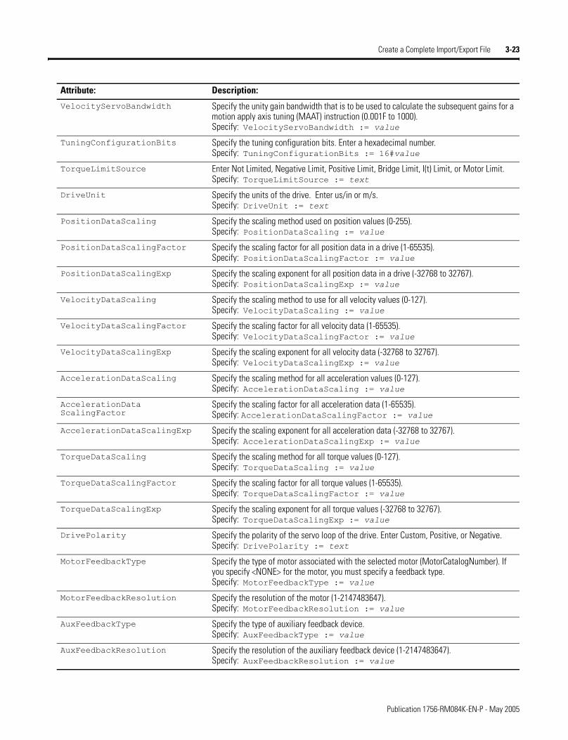
Create a Complete Import/Export File 3-23
VelocityServoBandwidth Specify the unity gain bandwidth that is to be used to calculate the subsequent gains for a motion apply axis tuning (MAAT) instruction (0.001F to 1000).Specify: VelocityServoBandwidth := value
TuningConfigurationBits Specify the tuning configuration bits. Enter a hexadecimal number.Specify: TuningConfigurationBits := 16#value
TorqueLimitSource Enter Not Limited, Negative Limit, Positive Limit, Bridge Limit, I(t) Limit, or Motor Limit.Specify: TorqueLimitSource := text
DriveUnit Specify the units of the drive. Enter us/in or m/s.Specify: DriveUnit := text
PositionDataScaling Specify the scaling method used on position values (0-255).Specify: PositionDataScaling := value
PositionDataScalingFactor Specify the scaling factor for all position data in a drive (1-65535).Specify: PositionDataScalingFactor := value
PositionDataScalingExp Specify the scaling exponent for all position data in a drive (-32768 to 32767).Specify: PositionDataScalingExp := value
VelocityDataScaling Specify the scaling method to use for all velocity values (0-127).Specify: VelocityDataScaling := value
VelocityDataScalingFactor Specify the scaling factor for all velocity data (1-65535).Specify: VelocityDataScalingFactor := value
VelocityDataScalingExp Specify the scaling exponent for all velocity data (-32768 to 32767).Specify: VelocityDataScalingExp := value
AccelerationDataScaling Specify the scaling method for all acceleration values (0-127).Specify: AccelerationDataScaling := value
AccelerationData ScalingFactor
Specify the scaling factor for all acceleration data (1-65535).Specify: AccelerationDataScalingFactor := value
AccelerationDataScalingExp Specify the scaling exponent for all acceleration data (-32768 to 32767).Specify: AccelerationDataScalingExp := value
TorqueDataScaling Specify the scaling method for all torque values (0-127).Specify: TorqueDataScaling := value
TorqueDataScalingFactor Specify the scaling factor for all torque values (1-65535).Specify: TorqueDataScalingFactor := value
TorqueDataScalingExp Specify the scaling exponent for all torque values (-32768 to 32767).Specify: TorqueDataScalingExp := value
DrivePolarity Specify the polarity of the servo loop of the drive. Enter Custom, Positive, or Negative.Specify: DrivePolarity := text
MotorFeedbackType Specify the type of motor associated with the selected motor (MotorCatalogNumber). If you specify <NONE> for the motor, you must specify a feedback type.Specify: MotorFeedbackType := value
MotorFeedbackResolution Specify the resolution of the motor (1-2147483647).Specify: MotorFeedbackResolution := value
AuxFeedbackType Specify the type of auxiliary feedback device.Specify: AuxFeedbackType := value
AuxFeedbackResolution Specify the resolution of the auxiliary feedback device (1-2147483647).Specify: AuxFeedbackResolution := value
Attribute: Description:
Publication 1756-RM084K-EN-P - May 2005
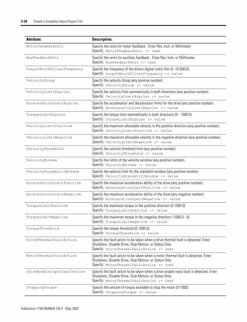
3-24 Create a Complete Import/Export File
MotorFeedbackUnit Specify the units for motor feedback. Enter Rev, Inch, or Millimeter.Specify: MotorFeedbackUnit := text
AuxFeedbackUnit Specify the units for auxiliary feedback. Enter Rev, Inch, or Millimeter.Specify: AuxFeedbackUnit := text
OutputNotchFilterFrequency Specify the frequency of the drive’s digital notch filer (0 -10,000.0).Specify: OutputNotchFilterFrequency := value
VelocityDroop Specify the velocity droop (any positive number).Specify: VelocityDroop := value
VelocityLimitBipolar Specify the velocity limit symmetrically in both directions (any positive number).Specify: VelocityLimitBipolar := value
AccelerationLimitBipolar Specify the acceleration and deceleration limits for the drive (any positive number).Specify: AccelerationLimitBipolar := value
TorqueLimitBipolar Specify the torque limit symmetrically in both directions (0 - 1000.0).Specify: TorqueLimitBipolar := value
VelocityLimitPositive Specify the maximum allowable velocity in the positive direction (any positive number).Specify: VelocityLimitPositive := value
VelocityLimitNegative Specify the maximum allowable velocity in the negative direction (any positive number).Specify: VelocityLimitNegative := value
VelocityThreshold Specify the velocity threshold limit (any positive number).Specify: VelocityThreshold := value
VelocityWindow Specify the limits of the velocity window (any positive number).Specify: VelocityWindow := value
VelocityStandstillWindow Specify the velocity limit for the standstill window (any positive number).Specify: VelocityStandstillWindow := value
AccelerationLimitPositive Specify the maximum acceleration ability of the drive (any positive number).Specify: AccelerationLimitPositive := value
AccelerationLimitNegative Specify the maximum acceleration ability of the drive (any negative number).Specify: AccelerationLimitNegative := value
TorqueLimitPositive Specify the maximum torque in the positive direction (0-1000.0).Specify: TorqueLimitPositive := value
TorqueLimitNegative Specify the maximum torque in the negative direction (-1000.0 - 0).Specify: TorqueLimitNegative := value
TorqueThreshold Specify the torque threshold (0-1000.0).Specify: TorqueThreshold := value
DriveThermalFaultAction Specify the fault action to be taken when a drive thermal fault is detected. Enter Shutdown, Disable Drive, Stop Motion, or Status Only.Specify: DriveThermalFaultAction := text
MotorThermalFaultAction Specify the fault action to be taken when a motor thermal fault is detected. Enter Shutdown, Disable Drive, Stop Motion, or Status Only.Specify: MotorThermalFaultAction := text
DriveEnableInputFaultAction Specify the fault action to be taken when a drive enable input fault is detected. Enter Shutdown, Disable Drive, Stop Motion, or Status Only.Specify: MotorThermalFaultAction := text
StoppingTorque Specify the amount of torque available to stop the motor (0-1000).Specify: StoppingTorque := value
Attribute: Description:
Publication 1756-RM084K-EN-P - May 2005
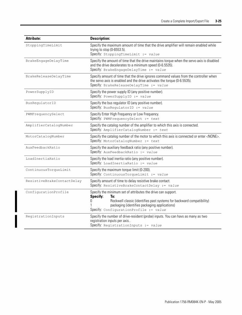
Create a Complete Import/Export File 3-25
StoppingTimeLimit Specify the maximum amount of time that the drive amplifier will remain enabled while trying to stop (0-6553.5).Specify: StoppingTimeLimit := value
BrakeEngageDelayTime Specify the amount of time that the drive maintains torque when the servo axis is disabled and the drive decelerates to a minimum speed (0-6.5535).Specify: BrakeEngageDelayTime := value
BrakeReleaseDelayTime Specify amount of time that the drive ignores command values from the controller when the servo axis is enabled and the drive activates the torque (0-6.5535).Specify: BrakeReleaseDelayTime := value
PowerSupplyID Specify the power supply ID (any positive number).Specify: PowerSupplyID := value
BusRegulatorID Specify the bus regulator ID (any positive number).Specify: BusRegulatorID := value
PWMFrequencySelect Specify Enter High Frequency or Low Frequency.Specify: PWMFrequencySelect := text
AmplifierCatalogNumber Specify the catalog number of the amplifier to which this axis is connected.Specify: AmplifierCatalogNumber := text
MotorCatalogNumber Specify the catalog number of the motor to which this axis is connected or enter <NONE>.Specify: MotorCatalogNumber := text
AuxFeedbackRatio Specify the auxiliary feedback ratio (any positive number).Specify: AuxFeedbackRatio := value
LoadInertiaRatio Specify the load inertia ratio (any positive number).Specify: LoadInertiaRatio := value
ContinuousTorqueLimit Specify the maximum torque limit (0-200).Specify: ContinuousTorqueLimit := value
ResistiveBrakeContactDelay Specify amount of time to delay resistive brake contact.Specify: ResistiveBrakeContactDelay := value
ConfigurationProfile Specify the minimum set of attributes the drive can support.Specify: To: 0 Rockwell classic (identifies past systems for backward compatibility) 1 packaging (identifies packaging applications)Specify: ConfigurationProfile := value
RegistrationInputs Specify the number of drive-resident (probe) inputs. You can havs as many as two registration inputs per axis..Specify: RegistrationInputs := value
Attribute: Description:
Publication 1756-RM084K-EN-P - May 2005
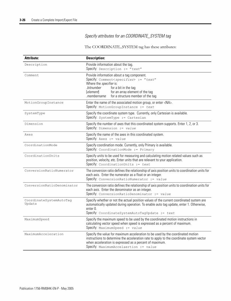
3-26 Create a Complete Import/Export File
Specify attributes for an COORDINATE_SYSTEM tag
The COORDINATE_SYSTEM tag has these attributes:
Attribute: Description:
Description Provide information about the tag.Specify: Description := �text�
Comment Provide information about a tag component.Specify: Comment<specifier> := �text�Where the specifier is:.bitnumber for a bit in the tag[element] for an array element of the tag .membername for a structure member of the tag
MotionGroupInstance Enter the name of the associated motion group, or enter <NA>. Specify: MotionGroupInstance := text
SystemType Specify the coordinate system type. Currently, only Cartesian is available.Specify: SystemType := Cartesian
Dimension Specify the number of axes that this coordinated system supports. Enter 1, 2, or 3.Specify: Dimension := value
Axes Specify the name of the axes in this coordinated system.Specify: Axes := value
CoordinationMode Specify coordination mode. Currently, only Primary is available.Specify: CoordinationMode := Primary
CoordinationUnits Specify units to be used for measuring and calculating motion related values such as position, velocity, etc. Enter units that are relevant to your application.Specify: CoordinationUnits := text
ConversionRatioNumerator The conversion ratio defines the relationship of axis position units to coordination units for each axis. Enter the numerator as a float or an integer. Specify: ConversionRatioNumerator := value
ConversionRatioDenominator The conversion ratio defines the relationship of axis position units to coordination units for each axis. Enter the denominator as an integer.Specify: ConversionRatioDenominator := value
CoordinateSystemAutoTag Update
Specify whether or not the actual position values of the current coordinated system are automatically updated during operation. To enable auto tag update, enter 1. Otherwise, enter 0. Specify: CoordinateSystemAutoTagUpdate := text
MaximumSpeed Specify the maximum speed to be used by the coordinated motion instructions in calculating vector speed when speed is expressed as a percent of maximum.Specify: MaximumSpeed := value
MaximumAcceleration Specify the value for maximum acceleration to be used by the coordinated motion instructions to determine the acceleration rate to apply to the coordinate system vector when acceleration is expressed as a percent of maximum.Specify: MaximumAccelaertion := value
Publication 1756-RM084K-EN-P - May 2005
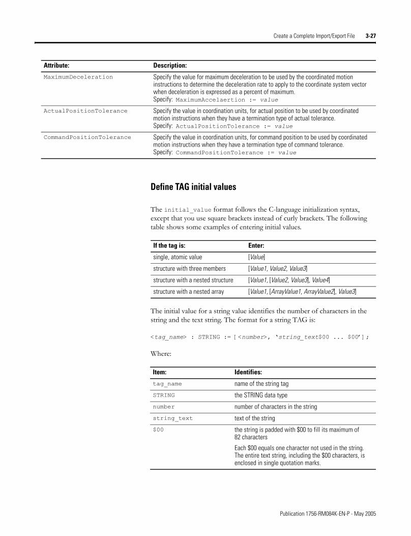
Create a Complete Import/Export File 3-27
Define TAG initial values
The initial_value format follows the C-language initialization syntax, except that you use square brackets instead of curly brackets. The following table shows some examples of entering initial values.
The initial value for a string value identifies the number of characters in the string and the text string. The format for a string TAG is:
<tag_name> : STRING := [<number>, �string_text$00 ... $00�];
Where:
MaximumDeceleration Specify the value for maximum deceleration to be used by the coordinated motion instructions to determine the deceleration rate to apply to the coordinate system vector when deceleration is expressed as a percent of maximum.Specify: MaximumAccelaertion := value
ActualPositionTolerance Specify the value in coordination units, for actual position to be used by coordinated motion instructions when they have a termination type of actual tolerance.Specify: ActualPositionTolerance := value
CommandPositionTolerance Specify the value in coordination units, for command position to be used by coordinated motion instructions when they have a termination type of command tolerance.Specify: CommandPositionTolerance := value
Attribute: Description:
If the tag is: Enter:
single, atomic value [Value]
structure with three members [Value1, Value2, Value3]
structure with a nested structure [Value1, [Value2, Value3], Value4]
structure with a nested array [Value1, [ArrayValue1, ArrayValue2], Value3]
Item: Identifies:
tag_name name of the string tag
STRING the STRING data type
number number of characters in the string
string_text text of the string
$00 the string is padded with $00 to fill its maximum of 82 characters
Each $00 equals one character not used in the string.The entire text string, including the $00 characters, is enclosed in single quotation marks.
Publication 1756-RM084K-EN-P - May 2005
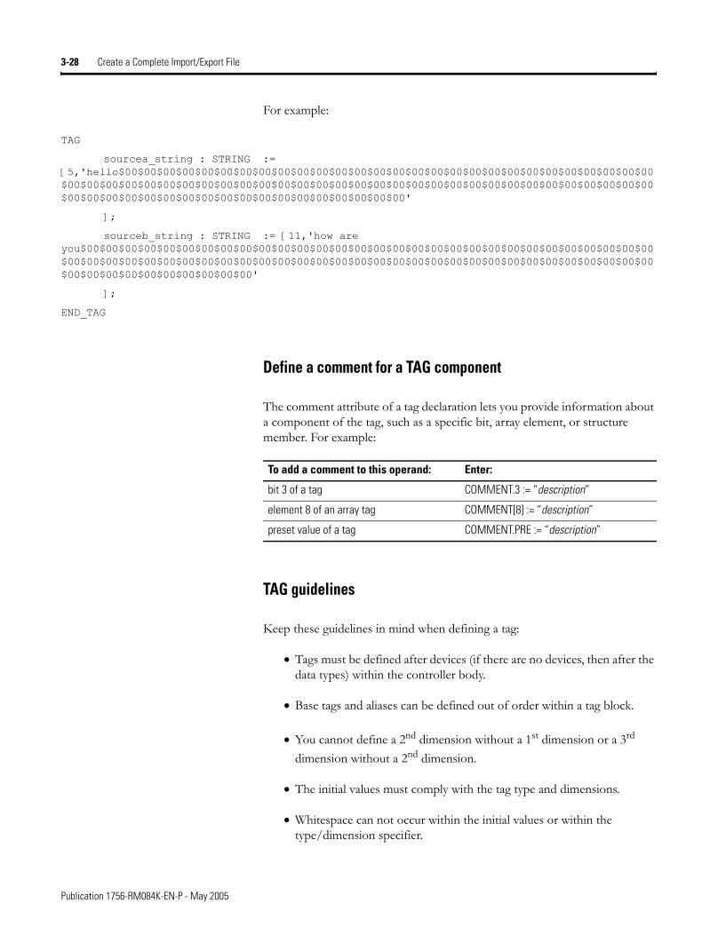
3-28 Create a Complete Import/Export File
For example:
TAG
sourcea_string : STRING := [5,'hello$00$00$00$00$00$00$00$00$00$00$00$00$00$00$00$00$00$00$00$00$00$00$00$00$00$00$00$00$00$00$00$00$00$00$00$00$00$00$00$00$00$00$00$00$00$00$00$00$00$00$00$00$00$00$00$00$00$00$00$00$00$00$00$00$00$00$00$00$00$00$00$00$00$00$00$00$00'
];
sourceb_string : STRING := [11,'how are you$00$00$00$00$00$00$00$00$00$00$00$00$00$00$00$00$00$00$00$00$00$00$00$00$00$00$00$00$00$00$00$00$00$00$00$00$00$00$00$00$00$00$00$00$00$00$00$00$00$00$00$00$00$00$00$00$00$00$00$00$00$00$00$00$00$00$00$00$00$00$00'
];
END_TAG
Define a comment for a TAG component
The comment attribute of a tag declaration lets you provide information about a component of the tag, such as a specific bit, array element, or structure member. For example:
TAG guidelines
Keep these guidelines in mind when defining a tag:
• Tags must be defined after devices (if there are no devices, then after the data types) within the controller body.
• Base tags and aliases can be defined out of order within a tag block.
• You cannot define a 2nd dimension without a 1st dimension or a 3rd dimension without a 2nd dimension.
• The initial values must comply with the tag type and dimensions.
• Whitespace can not occur within the initial values or within the type/dimension specifier.
To add a comment to this operand: Enter:
bit 3 of a tag COMMENT.3 := “description”
element 8 of an array tag COMMENT[8] := “description”
preset value of a tag COMMENT.PRE := “description”
Publication 1756-RM084K-EN-P - May 2005
Create a Complete Import/Export File 3-29
TAG examples
TAG
bits : MySint := [0];
dest : INT (RADIX := Decimal) := 0;
overflow OF bits.MyBit0 (RADIX := Binary);
source : REAL (RADIX := Exponential) := 0.0;
timer : TIMER[3] := [[0,0,100],[0,10,100],[0,0,50]];
END_TAG
This example shows forced tag data:
TAG
dint_a : DINT (RADIX := Decimal) := 0;
int_a : INT (RADIX := Decimal) := 0;
tag_a : UDT_A (ProduceCount := 2) := [0,0],
TagForceData := [0,0,0,0,1,0,-1,-1,1,0,-72,34];
END_TAG
Define a Program A PROGRAM component follows this structure:
PROGRAM <program_name> [(Attributes)]
[TAG declaration]
[ROUTINE declaration]
[FBD_ROUTINE declaration]
[ST_ROUTINE declaration]
[SFC_ROUTINE declaration]
END_PROGRAM
Where:
Item: Identifies:
program_name the program
Attributes attributes of the program (such as MAIN or FAULT)can also contain a description of the programenclose in parenthesisseparate each attribute with a comma (,)
TAG program-scoped tagsfollows same format as controller-scoped tagssee page 3-12
ROUTINE ladder logic routine for this programsee chapter 4
Publication 1756-RM084K-EN-P - May 2005
3-30 Create a Complete Import/Export File
You can intermix ROUTINE, FBD_ROUTINE, ST_ROUTINE, and SFC_ROUTINE declarations.
The maximum number of programs depends on the type of controller:
Specify PROGRAM attributes
Specify these attributes for a PROGRAM:
FBD_ROUTINE function block diagram routine for this programsee chapter 5
ST_ROUTINE structured text routine for this programsee chapter 6
SFC_ROUTINE sequential function chart routine for this programsee chapter 7
Controller: Maximum Number of Programs:
ControlLogix 100(32 in firmware revisions prior to 15)
SoftLogix5800 100(32 in firmware revisions prior to 15)
FlexLogix 32
CompactLogix 32
DriveLogix 32
Item: Identifies:
Attribute: Description:
Description Provide information about the program.Specify: Description := �text�
Type Specify the type of program. If this program is a Equipment Phase program, enter EquipmentPhase. Otherwise, enter Normal.Specify: Type := text
Main Name of the main routine of the program (40 characters maximum).Specify: Main := name
Fault Name of the program fault routine, if any (40 characters maximum).Specify: Fault := name
Mode Enter 0 for not testing edits; enter 1 for testing edits.Specify: Mode := value
DisableFlag Enter 1 to disable the program; enter 0 to enable the program.Specify: DisableFlag := value
Publication 1756-RM084K-EN-P - May 2005
Create a Complete Import/Export File 3-31
Specify PROGRAM attributes for EquipmentPhase Programs
In addition to the PROGRAM connection attributes previously described, specify these attributes for an Equipment Phase program (PROGRAM Type = EquipmentPhase):
PROGRAM guidelines
Keep in mind these guidelines when defining a program:
• The MAIN and FAULT attributes can be defined in any order.
• The TAG declaration block must occur before the routine block.
• All tag collection declaration blocks that occur in a program definition block are imported as tags of a given program and can only be seen by routines under that program. Controller tags, on the other hand can be seen by routines in any program.
Attribute: Description:
Prestate Name of the prestate routine (40 characters maximum).Specify: Prestate := name
InitialStepIndex Specify an integer value for the initial step index of the phase.Specify: InitialStepIndex := number
InitialState Specify state of the phase. Enter Idle (default), Aborted, Stopped, or Complete.Specify: InitialState := text
CompleteStateIfNot Impl
If the phase does not implement all the expected states, enter StateComplete (default) so the program can continue to execute when it expects a state that was omitted. The program ignores the omitted state and continues to the next state. Otherwise, enter NoAction.Specify: CompleteStateIfNotImpl := text
LossOfCommCmd If the phase uses an external sequencer, such as RSBizWare Batch software, specify that appropriate action to take if communication fails between the controller and the external sequencer. Enter Abort, Hold, Stop, or None (default).Specify: LossOfCommCmd := text
ExternalRequest Action
Specify how to handle an external request (PXRQ instruction) that is in process when the phase receives the command to go to a Holding state. Enter Clear to abort outstanding external requests. Otherwise, enter None (default).Specify: ExternalRequestAction := text
EquipmentId The RSBizware Batch equipment identifier for the Equipment Phase. This value is set by the RSBizware Batch software when you synchronize with an RSLogix 5000 project file. Do not modify this value.
RecipePhaseNames The RSBizware Batch recipe phases for the Equipment Phase. This value is set by the RSBizware Batch software when you synchronize with an RSLogix 5000 project file. Do not modify this value.
Publication 1756-RM084K-EN-P - May 2005
3-32 Create a Complete Import/Export File
PROGRAM example
PROGRAM Prg1 (Main := RoutineB, Description := "I $'am$'" " $0034 a $"program$"")
TAG
st11 : DINT (RADIX := Decimal, ProduceCount := 0) := 2;
st12 : BOOL (RADIX := Binary, ProduceCount := 0) := 2#00000000;
END_TAG
ROUTINE RoutineA
JSR(_2_LADDER, 0);
END_ROUTINE
ROUTINE RoutineB
RC: "$L ** ;MORE $";STUFF" do not include "more"; xic(st11) ote(st12);
END_ROUTINE
END_PROGRAM
EquipmentPhase PROGRAM example
PROGRAM Add_Water (Type := EquipmentPhase, PreState := Prestate_Routine, FAULT := Fault_Routine, MODE := 0, DisableFlag := 0, InitialStepIndex := 1, InitialState := Idle, CompleteStateIfNotImpl := StateComplete, LossOfCommCmd := None, ExternalRequestAction := None)
[TAG declaraions]
[ROUTINE declaraions]
[SFC_ROUTINE declaraions]
END_PROGRAM
Publication 1756-RM084K-EN-P - May 2005
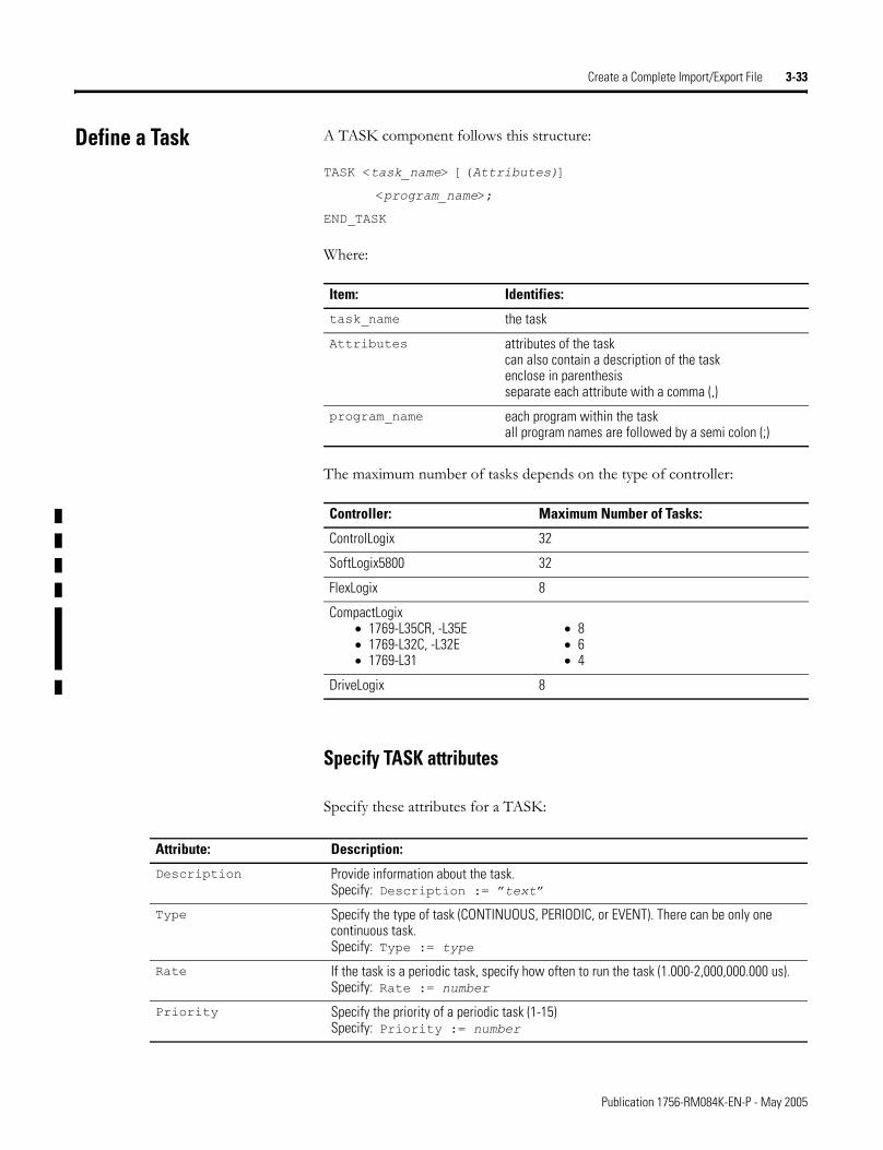
Create a Complete Import/Export File 3-33
Define a Task A TASK component follows this structure:
TASK <task_name> [(Attributes)]
<program_name>;
END_TASK
Where:
The maximum number of tasks depends on the type of controller:
Specify TASK attributes
Specify these attributes for a TASK:
Item: Identifies:
task_name the task
Attributes attributes of the taskcan also contain a description of the taskenclose in parenthesisseparate each attribute with a comma (,)
program_name each program within the taskall program names are followed by a semi colon (;)
Controller: Maximum Number of Tasks:
ControlLogix 32
SoftLogix5800 32
FlexLogix 8
CompactLogix• 1769-L35CR, -L35E• 1769-L32C, -L32E• 1769-L31
• 8• 6• 4
DriveLogix 8
Attribute: Description:
Description Provide information about the task.Specify: Description := �text�
Type Specify the type of task (CONTINUOUS, PERIODIC, or EVENT). There can be only one continuous task.Specify: Type := type
Rate If the task is a periodic task, specify how often to run the task (1.000-2,000,000.000 us). Specify: Rate := number
Priority Specify the priority of a periodic task (1-15)Specify: Priority := number
Publication 1756-RM084K-EN-P - May 2005
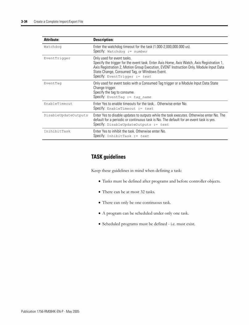
3-34 Create a Complete Import/Export File
TASK guidelines
Keep these guidelines in mind when defining a task:
• Tasks must be defined after programs and before controller objects.
• There can be at most 32 tasks.
• There can only be one continuous task.
• A program can be scheduled under only one task.
• Scheduled programs must be defined - i.e. must exist.
Watchdog Enter the watchdog timeout for the task (1.000-2,000,000.000 us).Specify: Watchdog := number
EventTrigger Only used for event tasks.Specify the trigger for the event task. Enter Axis Home, Axis Watch, Axis Registration 1, Axis Registration 2, Motion Group Execution, EVENT Instruction Only, Module Input Data State Change, Consumed Tag, or Windows Event.Specify: EventTrigger := text
EventTag Only used for event tasks with a Consumed Tag trigger or a Module Input Data State Change trigger.Specify the tag to consume.Specify: EventTag := tag_name
EnableTimeout Enter Yes to enable timeouts for the task, . Otherwise enter No.Specify: EnableTimeout := text
DisableUpdateOutputs Enter Yes to disable updates to outputs while the task executes. Otherwise enter No. The default for a periodic or continuous task is No. The default for an event task is yes.Specify: DisableUpdateOutputs := text
InihibitTask Enter Yes to inhibit the task. Otherwise enter No.Specify: InhibitTask := text
Attribute: Description:
Publication 1756-RM084K-EN-P - May 2005
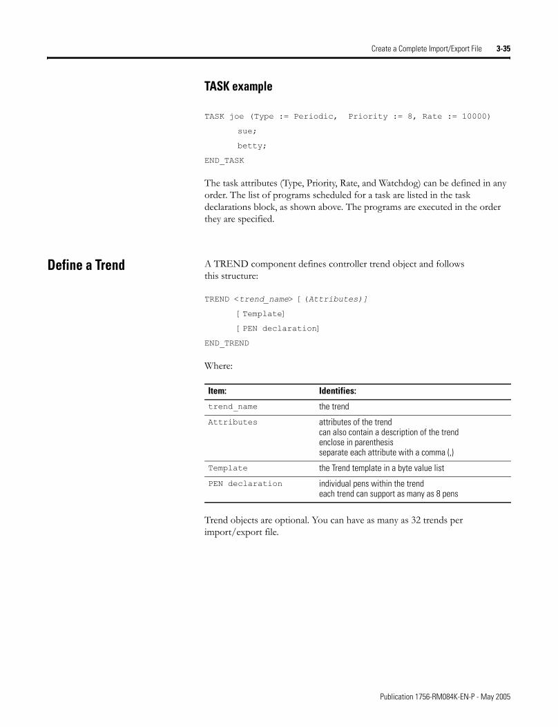
Create a Complete Import/Export File 3-35
TASK example
TASK joe (Type := Periodic, Priority := 8, Rate := 10000)
sue;
betty;
END_TASK
The task attributes (Type, Priority, Rate, and Watchdog) can be defined in any order. The list of programs scheduled for a task are listed in the task declarations block, as shown above. The programs are executed in the order they are specified.
Define a Trend A TREND component defines controller trend object and follows this structure:
TREND <trend_name> [(Attributes)]
[Template]
[PEN declaration]
END_TREND
Where:
Trend objects are optional. You can have as many as 32 trends per import/export file.
Item: Identifies:
trend_name the trend
Attributes attributes of the trendcan also contain a description of the trendenclose in parenthesisseparate each attribute with a comma (,)
Template the Trend template in a byte value list
PEN declaration individual pens within the trendeach trend can support as many as 8 pens
Publication 1756-RM084K-EN-P - May 2005
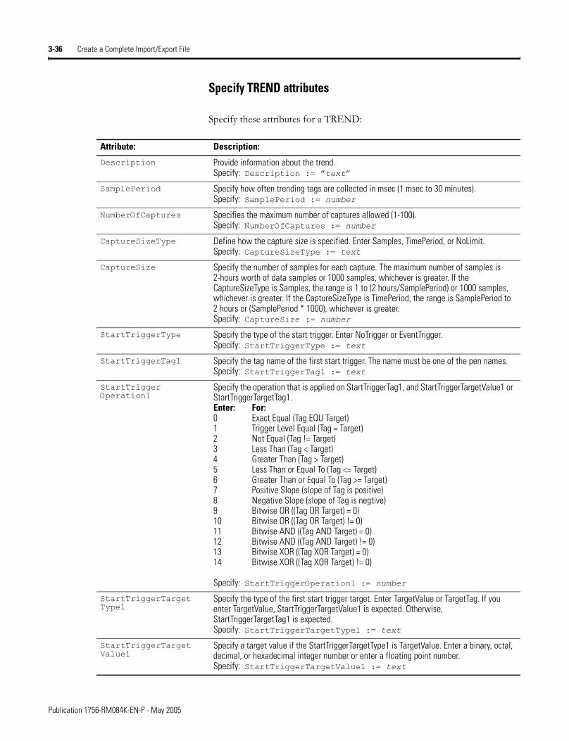
3-36 Create a Complete Import/Export File
Specify TREND attributes
Specify these attributes for a TREND:
Attribute: Description:
Description Provide information about the trend.Specify: Description := �text�
SamplePeriod Specify how often trending tags are collected in msec (1 msec to 30 minutes).Specify: SamplePeriod := number
NumberOfCaptures Specifies the maximum number of captures allowed (1-100). Specify: NumberOfCaptures := number
CaptureSizeType Define how the capture size is specified. Enter Samples, TimePeriod, or NoLimit.Specify: CaptureSizeType := text
CaptureSize Specify the number of samples for each capture. The maximum number of samples is 2-hours worth of data samples or 1000 samples, whichever is greater. If the CaptureSizeType is Samples, the range is 1 to (2 hours/SamplePeriod) or 1000 samples, whichever is greater. If the CaptureSizeType is TimePeriod, the range is SamplePeriod to 2 hours or (SamplePeriod * 1000), whichever is greater.Specify: CaptureSize := number
StartTriggerType Specify the type of the start trigger. Enter NoTrigger or EventTrigger.Specify: StartTriggerType := text
StartTriggerTag1 Specify the tag name of the first start trigger. The name must be one of the pen names.Specify: StartTriggerTag1 := text
StartTrigger Operation1
Specify the operation that is applied on StartTriggerTag1, and StartTriggerTargetValue1 or StartTriggerTargetTag1.Enter: For:0 Exact Equal (Tag EQU Target) 1 Trigger Level Equal (Tag = Target) 2 Not Equal (Tag != Target) 3 Less Than (Tag < Target) 4 Greater Than (Tag > Target) 5 Less Than or Equal To (Tag <= Target) 6 Greater Than or Equal To (Tag >= Target) 7 Positive Slope (slope of Tag is positive) 8 Negative Slope (slope of Tag is negtive) 9 Bitwise OR ((Tag OR Target) = 0) 10 Bitwise OR ((Tag OR Target) != 0) 11 Bitwise AND ((Tag AND Target) = 0) 12 Bitwise AND ((Tag AND Target) != 0) 13 Bitwise XOR ((Tag XOR Target) = 0) 14 Bitwise XOR ((Tag XOR Target) != 0)
Specify: StartTriggerOperation1 := number
StartTriggerTarget Type1
Specify the type of the first start trigger target. Enter TargetValue or TargetTag. If you enter TargetValue, StartTriggerTargetValue1 is expected. Otherwise, StartTriggerTargetTag1 is expected. Specify: StartTriggerTargetType1 := text
StartTriggerTarget Value1
Specify a target value if the StartTriggerTargetType1 is TargetValue. Enter a binary, octal, decimal, or hexadecimal integer number or enter a floating point number. Specify: StartTriggerTargetValue1 := text
Publication 1756-RM084K-EN-P - May 2005
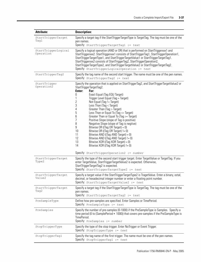
Create a Complete Import/Export File 3-37
StartTriggerTarget Tag1
Specify a target tag if the StartTriggerTargetType is TargetTag. The tag must be one of the pen names.Specify: StartTriggerTargetTag1 := text
StartTriggerLogical Operation
Specify a logical operation (AND or OR) that is performed on StartTriggerxxx1 and StartTriggerxxx2. StartTriggerxxx1 consists of StartTriggerTag1, StartTriggerOperation1, StartTriggerTargetType1, and StartTriggerTargetValue1 or StartTriggerTargetTag1. StartTriggerxxx2 consists of StartTriggerTag2, StartTriggerOperation2, StartTriggerTargetType2, and StartTriggerTargetValue2 or StartTriggerTargetTag2. Specify: StartTriggerLogicalOperation := text
StartTriggerTag2 Specify the tag name of the second start trigger. The name must be one of the pen names.Specify: StartTriggerTag2 := text
StartTrigger Operation2
Specify the operation that is applied on StartTriggerTag2, and StartTriggerTargetValue2 or StartTriggerTargetTag2.Enter: For:0 Exact Equal (Tag EQU Target) 1 Trigger Level Equal (Tag = Target) 2 Not Equal (Tag != Target) 3 Less Than (Tag < Target) 4 Greater Than (Tag > Target) 5 Less Than or Equal To (Tag <= Target) 6 Greater Than or Equal To (Tag >= Target) 7 Positive Slope (slope of Tag is positive) 8 Negative Slope (slope of Tag is negtive) 9 Bitwise OR ((Tag OR Target) = 0) 10 Bitwise OR ((Tag OR Target) != 0) 11 Bitwise AND ((Tag AND Target) = 0) 12 Bitwise AND ((Tag AND Target) != 0) 13 Bitwise XOR ((Tag XOR Target) = 0) 14 Bitwise XOR ((Tag XOR Target) != 0)
Specify: StartTriggerOperation2 := number
StartTriggerTarget Type2
Specify the type of the second start trigger target. Enter TargetValue or TargetTag. If you enter TargetValue, StartTriggerTargetValue2 is expected. Otherwise, StartTriggerTargetTag2 is expected. Specify: StartTriggerTargetType2 := text
StartTriggerTarget Value2
Specify a target value if the StartTriggerTargetType2 is TragetValue. Enter a binary, octal, decimal, or hexadecimal integer number or enter a floating point number.Specify: StartTriggerTargetValue2 := text
StartTriggerTarget Tag2
Specify a target tag if the StartTriggerTargetType is TargetTag. The tag must be one of the pen names.Specify: StartTriggerTargetTag2 := text
PreSampleType Define how pre-samples are specified. Enter Samples or TimePeriod.Specify: PreSampleType := text
PreSamples Specify the number of pre-samples (0-1000) if the PreSampleType is Samples. Specify a time period (0 to (SamplePeriod ∗ 1000)) that covers pre-samples if the PreSampleType is TimePeriod.Specify: PreSamples := number
StopTriggerType Specify the type of the stop trigger. Enter NoTrigger or Event Trigger.Specify: StopTriggerType := text
StopTriggerTag1 Specify the tag name of the first trigger. The name must be one of the pen names.Specify: StopTriggerTag1 := text
Attribute: Description:
Publication 1756-RM084K-EN-P - May 2005
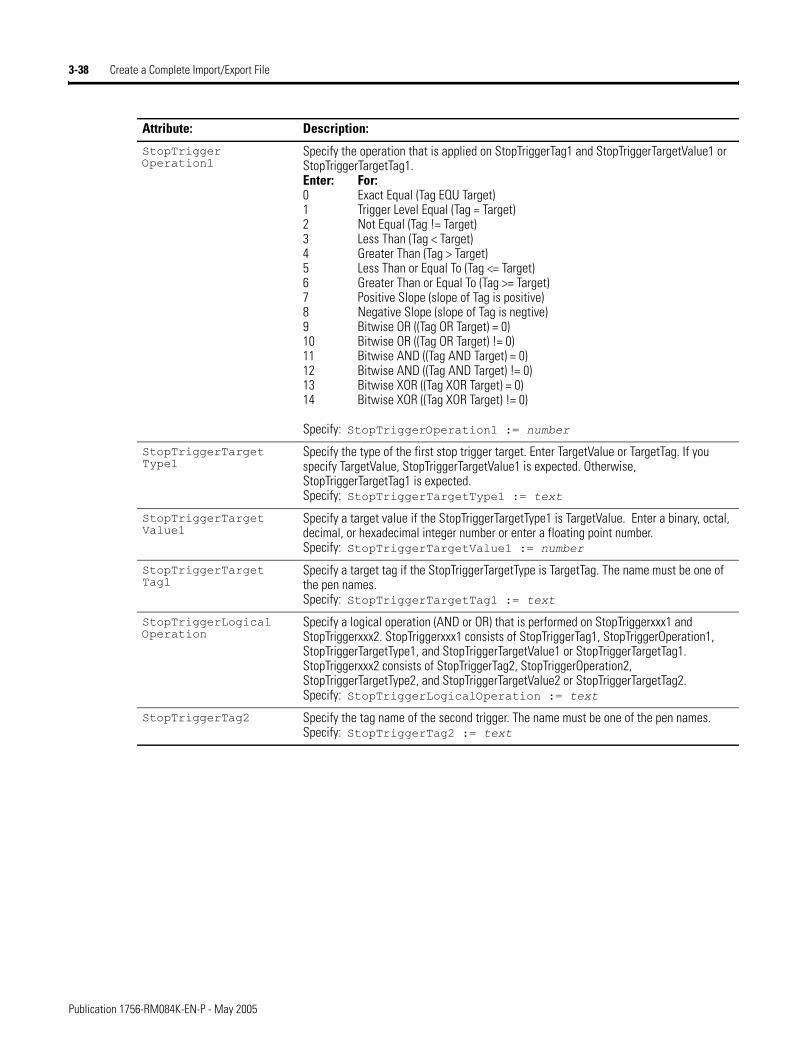
3-38 Create a Complete Import/Export File
StopTrigger Operation1
Specify the operation that is applied on StopTriggerTag1 and StopTriggerTargetValue1 or StopTriggerTargetTag1.Enter: For:0 Exact Equal (Tag EQU Target) 1 Trigger Level Equal (Tag = Target) 2 Not Equal (Tag != Target) 3 Less Than (Tag < Target) 4 Greater Than (Tag > Target) 5 Less Than or Equal To (Tag <= Target) 6 Greater Than or Equal To (Tag >= Target) 7 Positive Slope (slope of Tag is positive) 8 Negative Slope (slope of Tag is negtive) 9 Bitwise OR ((Tag OR Target) = 0) 10 Bitwise OR ((Tag OR Target) != 0) 11 Bitwise AND ((Tag AND Target) = 0) 12 Bitwise AND ((Tag AND Target) != 0) 13 Bitwise XOR ((Tag XOR Target) = 0) 14 Bitwise XOR ((Tag XOR Target) != 0)
Specify: StopTriggerOperation1 := number
StopTriggerTarget Type1
Specify the type of the first stop trigger target. Enter TargetValue or TargetTag. If you specify TargetValue, StopTriggerTargetValue1 is expected. Otherwise, StopTriggerTargetTag1 is expected. Specify: StopTriggerTargetType1 := text
StopTriggerTarget Value1
Specify a target value if the StopTriggerTargetType1 is TargetValue. Enter a binary, octal, decimal, or hexadecimal integer number or enter a floating point number.Specify: StopTriggerTargetValue1 := number
StopTriggerTarget Tag1
Specify a target tag if the StopTriggerTargetType is TargetTag. The name must be one of the pen names.Specify: StopTriggerTargetTag1 := text
StopTriggerLogical Operation
Specify a logical operation (AND or OR) that is performed on StopTriggerxxx1 and StopTriggerxxx2. StopTriggerxxx1 consists of StopTriggerTag1, StopTriggerOperation1, StopTriggerTargetType1, and StopTriggerTargetValue1 or StopTriggerTargetTag1. StopTriggerxxx2 consists of StopTriggerTag2, StopTriggerOperation2, StopTriggerTargetType2, and StopTriggerTargetValue2 or StopTriggerTargetTag2. Specify: StopTriggerLogicalOperation := text
StopTriggerTag2 Specify the tag name of the second trigger. The name must be one of the pen names.Specify: StopTriggerTag2 := text
Attribute: Description:
Publication 1756-RM084K-EN-P - May 2005
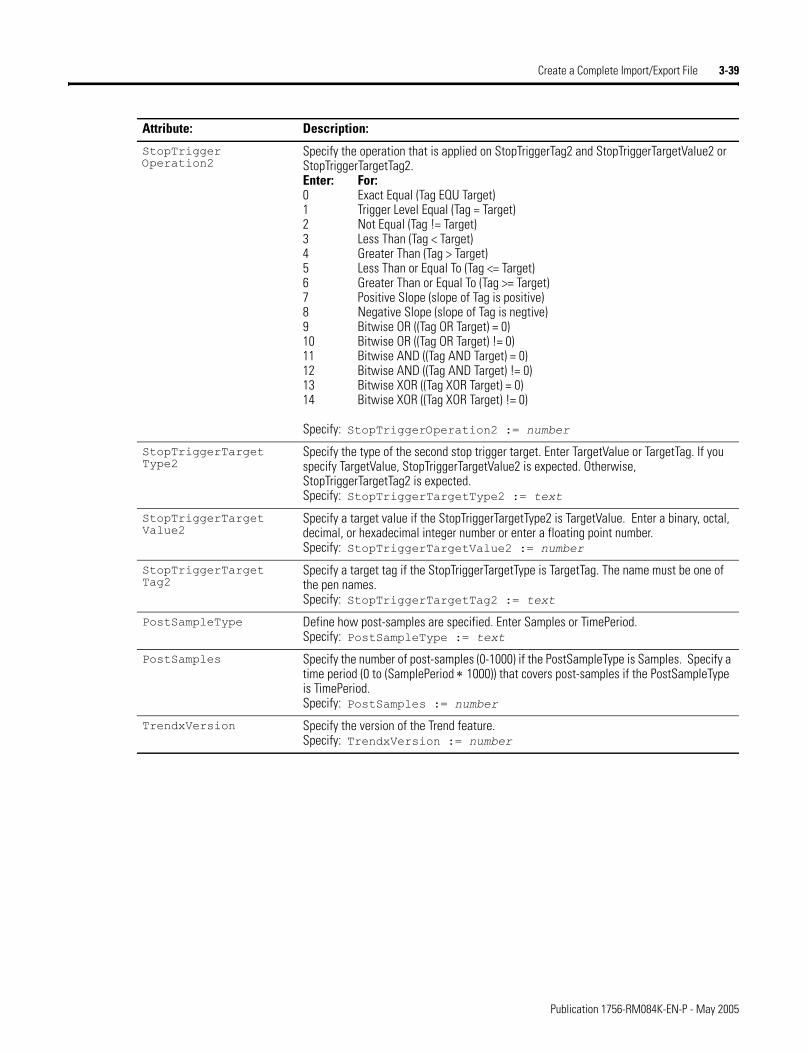
Create a Complete Import/Export File 3-39
StopTrigger Operation2
Specify the operation that is applied on StopTriggerTag2 and StopTriggerTargetValue2 or StopTriggerTargetTag2.Enter: For:0 Exact Equal (Tag EQU Target) 1 Trigger Level Equal (Tag = Target) 2 Not Equal (Tag != Target) 3 Less Than (Tag < Target) 4 Greater Than (Tag > Target) 5 Less Than or Equal To (Tag <= Target) 6 Greater Than or Equal To (Tag >= Target) 7 Positive Slope (slope of Tag is positive) 8 Negative Slope (slope of Tag is negtive) 9 Bitwise OR ((Tag OR Target) = 0) 10 Bitwise OR ((Tag OR Target) != 0) 11 Bitwise AND ((Tag AND Target) = 0) 12 Bitwise AND ((Tag AND Target) != 0) 13 Bitwise XOR ((Tag XOR Target) = 0) 14 Bitwise XOR ((Tag XOR Target) != 0)
Specify: StopTriggerOperation2 := number
StopTriggerTarget Type2
Specify the type of the second stop trigger target. Enter TargetValue or TargetTag. If you specify TargetValue, StopTriggerTargetValue2 is expected. Otherwise, StopTriggerTargetTag2 is expected. Specify: StopTriggerTargetType2 := text
StopTriggerTarget Value2
Specify a target value if the StopTriggerTargetType2 is TargetValue. Enter a binary, octal, decimal, or hexadecimal integer number or enter a floating point number.Specify: StopTriggerTargetValue2 := number
StopTriggerTarget Tag2
Specify a target tag if the StopTriggerTargetType is TargetTag. The name must be one of the pen names.Specify: StopTriggerTargetTag2 := text
PostSampleType Define how post-samples are specified. Enter Samples or TimePeriod.Specify: PostSampleType := text
PostSamples Specify the number of post-samples (0-1000) if the PostSampleType is Samples. Specify a time period (0 to (SamplePeriod ∗ 1000)) that covers post-samples if the PostSampleType is TimePeriod.Specify: PostSamples := number
TrendxVersion Specify the version of the Trend feature.Specify: TrendxVersion := number
Attribute: Description:
Publication 1756-RM084K-EN-P - May 2005
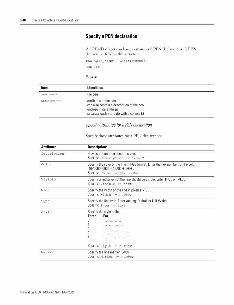
3-40 Create a Complete Import/Export File
Specify a PEN declaration
A TREND object can have as many as 8 PEN declarations. A PEN declaration follows this structure:PEN <pen_name> [(Attributes)];
END_PEN
Where:
Specify attributes for a PEN declaration
Specify these attributes for a PEN declaration:
Item: Identifies:
pen_name the pen
Attributes attributes of the pencan also contain a description of the penenclose in parenthesisseparate each attribute with a comma (,)
Attribute: Description:
Description Provide information about the pen.Specify: Description := �text�
Color Specify the color of the line in RGB format. Enter the hex number for the color (16#0000_0000 – 16#00FF_FFFF).Specify: Color := hex_number
Visible Specify whether or not the line should be visible. Enter TRUE or FALSE.Specify: Visible := text
Width Specify the width of the line in pixels (1-10).Specify: Width := number
Type Specify the line type. Enter Analog, Digital, or Full-Width.Specify: Type := text
Style Specify the style of line.Enter For 0 �����. 1 … … … … 2 . . . . . . . . . . . 3 … . … . … . … 4 … .. … .. … ..
Specify: Style := number
Marker Specify the line marker (0-83)Specify: Marker := number
Publication 1756-RM084K-EN-P - May 2005
Create a Complete Import/Export File 3-41
TREND guidelines
Keep these guidelines in mind when defining a trend:
• A trend can support as many as 8 PEN declarations.
• Export just the trend of a controller project by right-clicking on the trend in the Controller Organizer and selecting Export. This saves the trend as a .L5X file (XML format), which follows the same format as described above for the complete project .L5K file. For more information, see chapter 9.
• To import a trend .L5X file into a controller project, right-click on the Trends in the Controll Organizer and select Import.
Min Specify the minimum value for the pen. The minimum cannot be greater than or equal to the maximum.Specify: Min := number
Max Specify the maximum value for the pen. The maximum cannot be less than or equal to the minimum.Specify: Max := number
EngUnits Specify engineering units. For example, rpm, gallon, fps, degrees, etc..Specify: EngUnits := text
Attribute: Description:
Publication 1756-RM084K-EN-P - May 2005
3-42 Create a Complete Import/Export File
TREND example
TREND trend1 (SamplePeriod := 10,
NumberOfCaptures := 1,
CaptureSizeType := Samples,
CaptureSize := 60000,
StartTriggerType := No Trigger,
StopTriggerType := No Trigger,
TrendxVersion := 5.2)
Template := [208,207,17,224,161,177,26,225,0,0,0,0,0,0,0,0,0,0,0,0,0,0,0,0,62,0,3,0,254,255,9,0,6,0,0,0,0,0,0,0,0,0,0,0,1,0,0,0,1,0,0,0,0,0,0,0,0,16,0,0,2,0,0,0,1,0,0,0,254,255,255,255,0,0,0,0,0,0,0,0,255,255,255,255,255,255,,etc....
PEN Local:1:I.CHA_Status (Color := 16#00ff_0000,
Visible := 1,
Width := 1,
Type := Analog,
Style := 0,
Marker := 0,
Min := 0.0,
Max := 100.0)
END_PEN
PEN Local:1:I.CHB_Status (Color := 16#0000_ff00,
Visible := 1,
Width := 1,
Type := Analog,
Style := 0,
Marker := 0,
Min := 0.0,
Max := 100.0)
END_PEN
END_TREND
Publication 1756-RM084K-EN-P - May 2005
Create a Complete Import/Export File 3-43
Define Controller Objects A CONFIG component defines controller objects and follows this structure:
CONFIG <object_name> [(Attributes)]
[body]
END_CONFIG
Where:
Controller objects are optional. There can be only one of each controller object in an import/export file. Controller objects appear at the end of the import/export file.
Specify CONFIG Attributes The attributes depend on the type on CONFIG object. Some objects do not have any attributes. The following table lists those objects that have attributes and descriptions of each:
Item: Identifies:
object_name the controller objectsee the list of attributes below for a list of valid controller objects
Attributes attributes of the controller objectcan also contain a description of the controller objectenclose in parenthesisseparate each attribute with a comma (,)
Object: Attribute: Description:
ASCII XONXOFFEnable Specify whether to regulate the flow of incoming data. Enter 0 to disable XON/XOFF; enter 1 to enable XON/XOFF.Specify: XONXOFFEnable := value
DeleteMode Specify the delete mode. Enter 0 for Ignore; enter 1 for CRT; or enter 2 for Printer.Specify: DeleteMode := value
EchoMode Specify whether to echo data back to the device from which it was sent. Enter 0 to disable; enter 1 to enable.Specify: EchoMode := value
TerminationChars Specify the characters that designate the end of a line.Specify: TerminationChars := value
AppendChars Specify the characters to append to the end of a line.Specify: AppendChars := value
BufferSize Specify the maximum size of the data array (1-65535 bytes) to send and receive.Specify: BufferSize := value
ControllerDevice none none
CST SystemTimeMasterID Specify whether the controller is the coordinated system time master. Enter 16#0000 if the controller is not the CST master; enter 16#0001 if the controller is the CST master.Specify: CST := 16#value
Publication 1756-RM084K-EN-P - May 2005
3-44 Create a Complete Import/Export File
DF1 DuplicateDetection Specify whether to enable duplicate message detection, which ignores duplicate messages. Enter 0 to disable; enter 1 to enable.Specify: DuplicateDetection := value
ErrorDetection Specify the error detection method. Enter BCC Error or CRC Error.Specify: ErrorDetection := text
EnbeddedResponseEnable Specify the response method. Enter 0 to autodetect; enter 1 to enable.Specify: EnbeddedResponseEnable := value
DF1Mode Specify the DF1 mode. Enter Pt to Pt, Master, or Slave.Specify: DF1Mode := value
ACKTimeout Specify the time to wait for an acknowledgment to a message transmission. Enter an increment of 20ms (0-32767).Specify: ACKTimeout := value
NAKReceiveLimit Specify the number of NAKS (0-127) the controller can receive in response to a message before stopping transmission.Specify: NAKReceiveLimit := value
ENQTransmit Specify the number of inquiries (0-127) the controller sends after an ACK timeout.Specify: ENQTransmit := value
TransmitRetries Specify the number of attempted retries (0-127) without getting an acknowledgement before the message is deemed undeliverable.Specify: TransmitRetries := value
StationAddress Specify the current station link address (0-254).Specify: StationAddress := value
ReplyMessageWait Specify the time the master waits after receiving an acknowledgment to a master-initiated message before polling the slave for a response. Enter an increment of 20ms (0-65535).Specify: ReplyMessageWait := value
PollingMode Specify the polling mode. Enter on of these:• 1 for Message Based (slave can initiate messages)• 2 for Message Based (slave cannot initiate messages)• 3 for Standard (multiple message transfer for node scan)• 4 for Standard (single message transfer per node scan)
Specify: PollingMode := value
MasterMessageTransmit Specify when the master transmits. Enter 0 to transmit between station polls; enter 1 to transmit in poll sequence.Specify: MasterMessageTransmit := value
NormalPollNodeFile Specify the tag name of the structure that contains the normal poll node list. Or enter <NA>. The tag must specify Class = Standard.Specify: NormalPollNodeFile := value
NormalPollGroupSize Specify the total number (0-255) of active stations polled from the poll list.Specify: NormalPollGroupSize := value
PriorityPollNodeFile Specify the tag name of the structure that contains the priority poll node list. Or enter <NA>. The tag must specify Class = Standard.Specify: PriorityPollNodeFile := value
Object: Attribute: Description:
Publication 1756-RM084K-EN-P - May 2005
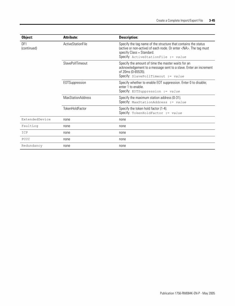
Create a Complete Import/Export File 3-45
DF1(continued)
ActiveStationFile Specify the tag name of the structure that contains the status (active or non-active) of each node. Or enter <NA>. The tag must specify Class = Standard.Specify: ActiveStationFile := value
SlavePollTimeout Specify the amount of time the master waits for an acknowledgement to a message sent to a slave. Enter an increment of 20ms (0-65535).Specify: SlavePollTimeout := value
EOTSuppression Specify whether to enable EOT suppression. Enter 0 to disable; enter 1 to enable.Specify: EOTSuppression := value
MaxStationAddress Specify the maximum station address (0-31).Specify: MaxStationAddress := value
TokenHoldFactor Specify the token hold factor (1-4).Specify: TokenHoldFactor := value
ExtendedDevice none none
FaultLog none none
ICP none none
PCCC none none
Redundancy none none
Object: Attribute: Description:
Publication 1756-RM084K-EN-P - May 2005
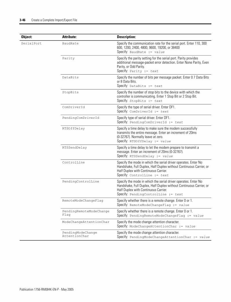
3-46 Create a Complete Import/Export File
SerialPort BaudRate Specify the communication rate for the serial port. Enter 110, 300 600, 1200, 2400, 4800, 9600, 19200, or 38400Specify: BaudRate := value
Parity Specify the parity setting for the serial port. Parity provides additional message-packet error detection. Enter None Parity, Even Parity, or Odd Parity.Specify: Parity := text
DataBits Specify the number of bits per message packet. Enter 0 7 Data Bits or 8 Data Bits.Specify: DataBits := text
StopBits Specify the number of stop bits to the device with which the controller is communicating. Enter 1 Stop Bit or 2 Stop Bit.Specify: StopBits := text
ComDriverId Specify the type of serial driver. Enter DF1.Specify: ComDriverId := text
PendingComDriverId Specify type of serial driver. Enter DF1.Specify: PendingComDriverId := text
RTSOffDelay Specify a time delay to make sure the modem successfully transmits the entire message. Enter an increment of 20ms (0-32767). Normally leave at zero.Specify: RTSOffDelay := value
RTSSendDelay Specify a time delay to let the modem prepare to transmit a message. Enter an increment of 20ms (0-32767).Specify: RTSSendDelay := value
ControlLine Specify the mode in which the serial driver operates. Enter No Handshake, Full Duplex, Half Duplex without Continuous Carrier, or Half Duplex with Continuous Carrier.Specify: ControlLine := text
PendingControlLine Specify the mode in which the serial driver operates. Enter No Handshake, Full Duplex, Half Duplex without Continuous Carrier, or Half Duplex with Continuous Carrier.Specify: PendingControlLine := text
RemoteModeChangeFlag Specify whether there is a remote change. Enter 0 or 1.Specify: RemoteModeChangeFlag := value
PendingRemoteModeChange Flag
Specify whether there is a remote change. Enter 0 or 1.Specify: PendingRemoteModeChangeFlag := value
ModeChangeAttentionChar Specify the mode change attention character.Specify: ModeChangeAttentionChar := value
PendingModeChange AttentionChar
Specify the mode change attention character.Specify: PendingModeChangeAttentionChar := value
Object: Attribute: Description:
Publication 1756-RM084K-EN-P - May 2005
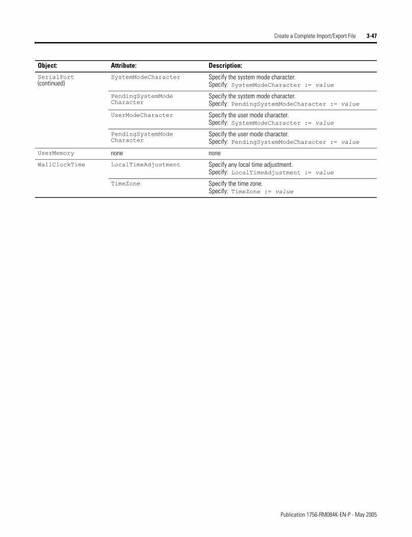
Create a Complete Import/Export File 3-47
SerialPort(continued)
SystemModeCharacter Specify the system mode character.Specify: SystemModeCharacter := value
PendingSystemMode Character
Specify the system mode character.Specify: PendingSystemModeCharacter := value
UserModeCharacter Specify the user mode character.Specify: SystemModeCharacter := value
PendingSystemMode Character
Specify the user mode character.Specify: PendingSystemModeCharacter := value
UserMemory none none
WallClockTime LocalTimeAdjustment Specify any local time adjustment.Specify: LocalTimeAdjustment := value
TimeZone Specify the time zone.Specify: TimeZone := value
Object: Attribute: Description:
Publication 1756-RM084K-EN-P - May 2005
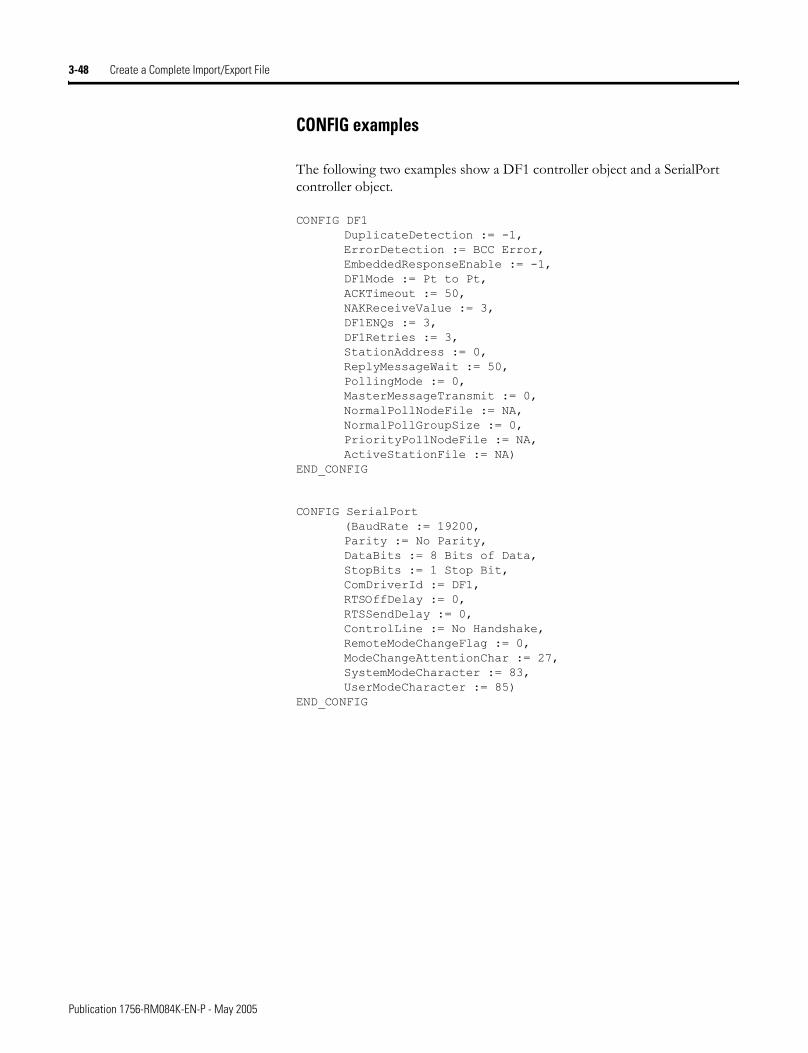
3-48 Create a Complete Import/Export File
CONFIG examples
The following two examples show a DF1 controller object and a SerialPort controller object.
CONFIG DF1 DuplicateDetection := -1, ErrorDetection := BCC Error, EmbeddedResponseEnable := -1, DF1Mode := Pt to Pt, ACKTimeout := 50, NAKReceiveValue := 3, DF1ENQs := 3, DF1Retries := 3, StationAddress := 0, ReplyMessageWait := 50, PollingMode := 0, MasterMessageTransmit := 0, NormalPollNodeFile := NA, NormalPollGroupSize := 0, PriorityPollNodeFile := NA, ActiveStationFile := NA)
END_CONFIG
CONFIG SerialPort (BaudRate := 19200, Parity := No Parity, DataBits := 8 Bits of Data, StopBits := 1 Stop Bit, ComDriverId := DF1, RTSOffDelay := 0, RTSSendDelay := 0, ControlLine := No Handshake, RemoteModeChangeFlag := 0, ModeChangeAttentionChar := 27, SystemModeCharacter := 83, UserModeCharacter := 85)
END_CONFIG
Publication 1756-RM084K-EN-P - May 2005
Chapter 4
Enter Ladder Diagram Logic
Introduction This chapter explains the how to enter ladder diagram logic in a complete import/export file.
Enter a Ladder Logic Routine
A ladder logic ROUTINE follows this structure:
ROUTINE <routine_name> [Attributes]
<ladder rungs>
END_ROUTINE
Where:
Specify ROUTINE attributes
Specify these attributes for a ROUTINE:
For information about: See page:
Enter a ladder logic routine 4-1
Enter rung logic 4-2
Enter comments 4-4
Enter instructions in neutral text language 4-4
Item: Identifies:
routine_name the routine
Attributes attributes of the routinecan also contain a description of the routineseparate each attribute with a comma (,)
ladder rungs ladder logic
Attribute: Description:
Description Provide information about the routine.Specify: Description := �text�
1 Publication 1756-RM084K-EN-P - May 2005
4-2 Enter Ladder Diagram Logic
Enter Rung Logic Enter rung logic within a ROUTINE component in an import/export file. Each rung follows this structure:
<RungType> : <RungNeutralText>;
Where:
The following rung types are available:
Rung guidelines
• Rungs are specified using neutral language. See the rest of this chapter for the neutral text language format for the supported instructions.
• Each rung ends with a semicolon (;).
Item: Identifies:
RungType the rung
RungNeutralText the logic
Rung type: Description:
N normal
I insert
D delete
IR insert with a replace
rR pending replace IR
R replace
rI pending replace I
rN pending replace N
e pending insert rung
er pending replace rung
Publication 1756-RM084K-EN-P - May 2005
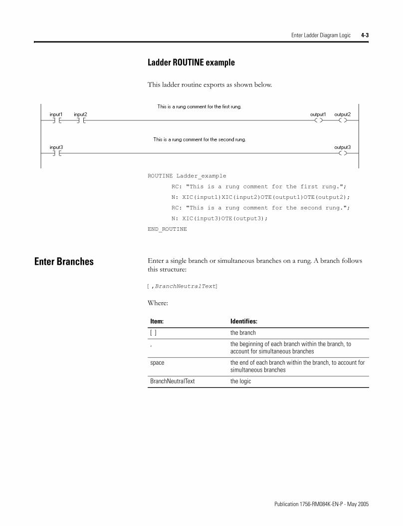
Enter Ladder Diagram Logic 4-3
Ladder ROUTINE example
This ladder routine exports as shown below.
ROUTINE Ladder_example
RC: "This is a rung comment for the first rung.";
N: XIC(input1)XIC(input2)OTE(output1)OTE(output2);
RC: "This is a rung comment for the second rung.";
N: XIC(input3)OTE(output3);
END_ROUTINE
Enter Branches Enter a single branch or simultaneous branches on a rung. A branch follows this structure:
[,BranchNeutralText]
Where:
Item: Identifies:
[ ] the branch
, the beginning of each branch within the branch, to account for simultaneous branches
space the end of each branch within the branch, to account for simultaneous branches
BranchNeutralText the logic
Publication 1756-RM084K-EN-P - May 2005
4-4 Enter Ladder Diagram Logic
Example with a single branch
N: XIC(conveyor_a)[,XIC(input_1) XIO(input_2) ]OTE(light_1);
Example with two simultaneous branches
N: XIC(conveyor_b)[,XIC(input_1) XIO(input_2) ,XIC(input_a) XIO(input_b) ]OTE(light_2);
Enter Rung Comments The comments for rungs are similar to those for components except that the syntax is a bit different. The rung comment syntax is:
RC: �comment� �more� �etc�;
A rung comment must be followed by a rung.
Enter Neutral Text for Ladder Instructions
The following tables lists each ladder instruction and its neutral text format. For details about a specific instruction, see one of these manuals:
Instruction Type: Documents:
Basic, sequential instruction
Logix5000 Controllers General Instructions Set Reference Manual, publication 1756-RM003
Process control or drives instruction
Logix5000 Controllers Process Control and Drives Instruction sSet Reference Manual, publication 1756-RM006
Motion instruction Logix5000 Controllers Motion Instructions Set Reference Manual, publication 1756-RM007
Instruction: Neutral text format:
ABL ABL(channel,serial_port_control,character_count);
ABS ABS(source,destination);
ACB ACB(channel,serial_port_control,character_count);
ACL ACL(channel,clear_serial_port_read,clear_serial_port_write);
ACS ACS(source,destination);
ADD ADD(source_A,source_B,destination);
AFI AFI();
AHL AHL(channel,ANDMask,ORMask,serial_port_control,channel_status);
AND AND(source_A,source_B,destination);
ARD ARD(channel,destination,serial_port_control,string_length, characters_read);
Publication 1756-RM084K-EN-P - May 2005
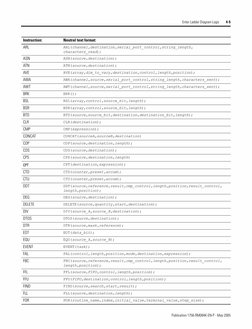
Enter Ladder Diagram Logic 4-5
ARL ARL(channel,destination,serial_port_control,string_length, characters_read);
ASN ASN(source,destination);
ATN ATN(source,destination);
AVE AVE(array,dim_to_vary,destination,control,length,position);
AWA AWA(channel,source,serial_port_control,string_length,characters_sent);
AWT AWT(channel,source,serial_port_control,string_length,characters_sent);
BRK BRK();
BSL BSL(array,control,source_bit,length);
BSR BSR(array,control,source_bit,length);
BTD BTD(source,source_bit,destination,destination_bit,length);
CLR CLR(destination);
CMP CMP(expression);
CONCAT CONCAT(sourceA,sourceB,destination)
COP COP(source,destination,length);
COS COS(source,destination);
CPS CPS(source,destination,length)
CPT CPT(destination,expression);
CTD CTD(counter,preset,accum);
CTU CTU(counter,preset,accum);
DDT DDT(source,reference,result,cmp_control,length,position,result_control, length,position);
DEG DEG(source,destination);
DELETE DELETE(source,quantity,start,destination);
DIV DIV(source_A,source_B,destination);
DTOS DTOS(source,destination);
DTR DTR(source,mask,reference);
EOT EOT(data_bit);
EQU EQU(source_A,source_B);
EVENT EVENT(task);
FAL FAL(control,length,position,mode,destination,expression);
FBC FBC(source,reference,result,cmp_control,length,position,result_control, length,position);
FFL FFL(source,FIFO,control,length,position);
FFU FFU(FIFO,destination,control,length,position);
FIND FIND(source,search,start,result);
FLL FLL(source,destination,length);
FOR FOR(routine_name,index,initial_value,terminal_value,step_size);
Instruction: Neutral text format:
Publication 1756-RM084K-EN-P - May 2005
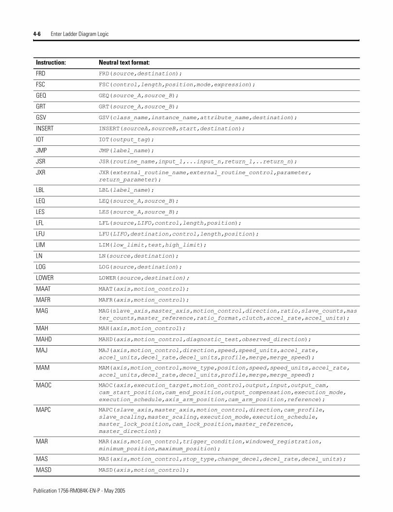
4-6 Enter Ladder Diagram Logic
FRD FRD(source,destination);
FSC FSC(control,length,position,mode,expression);
GEQ GEQ(source_A,source_B);
GRT GRT(source_A,source_B);
GSV GSV(class_name,instance_name,attribute_name,destination);
INSERT INSERT(sourceA,sourceB,start,destination);
IOT IOT(output_tag);
JMP JMP(label_name);
JSR JSR(routine_name,input_1,...input_n,return_1,..return_n);
JXR JXR(external_routine_name,external_routine_control,parameter, return_parameter);
LBL LBL(label_name);
LEQ LEQ(source_A,source_B);
LES LES(source_A,source_B);
LFL LFL(source,LIFO,control,length,position);
LFU LFU(LIFO,destination,control,length,position);
LIM LIM(low_limit,test,high_limit);
LN LN(source,destination);
LOG LOG(source,destination);
LOWER LOWER(source,destination);
MAAT MAAT(axis,motion_control);
MAFR MAFR(axis,motion_control);
MAG MAG(slave_axis,master_axis,motion_control,direction,ratio,slave_counts,master_counts,master_reference,ratio_format,clutch,accel_rate,accel_units);
MAH MAH(axis,motion_control);
MAHD MAHD(axis,motion_control,diagnostic_test,observed_direction);
MAJ MAJ(axis,motion_control,direction,speed,speed_units,accel_rate, accel_units,decel_rate,decel_units,profile,merge,merge_speed);
MAM MAM(axis,motion_control,move_type,position,speed,speed_units,accel_rate, accel_units,decel_rate,decel_units,profile,merge,merge_speed);
MAOC MAOC(axis,execution_target,motion_control,output,input,output_cam, cam_start_position,cam_end_position,output_compensation,execution_mode, execution_schedule,axis_arm_position,cam_arm_position,reference);
MAPC MAPC(slave_axis,master_axis,motion_control,direction,cam_profile, slave_scaling,master_scaling,execution_mode,execution_schedule, master_lock_position,cam_lock_position,master_reference, master_direction);
MAR MAR(axis,motion_control,trigger_condition,windowed_registration, minimum_position,maximum_position);
MAS MAS(axis,motion_control,stop_type,change_decel,decel_rate,decel_units);
MASD MASD(axis,motion_control);
Instruction: Neutral text format:
Publication 1756-RM084K-EN-P - May 2005
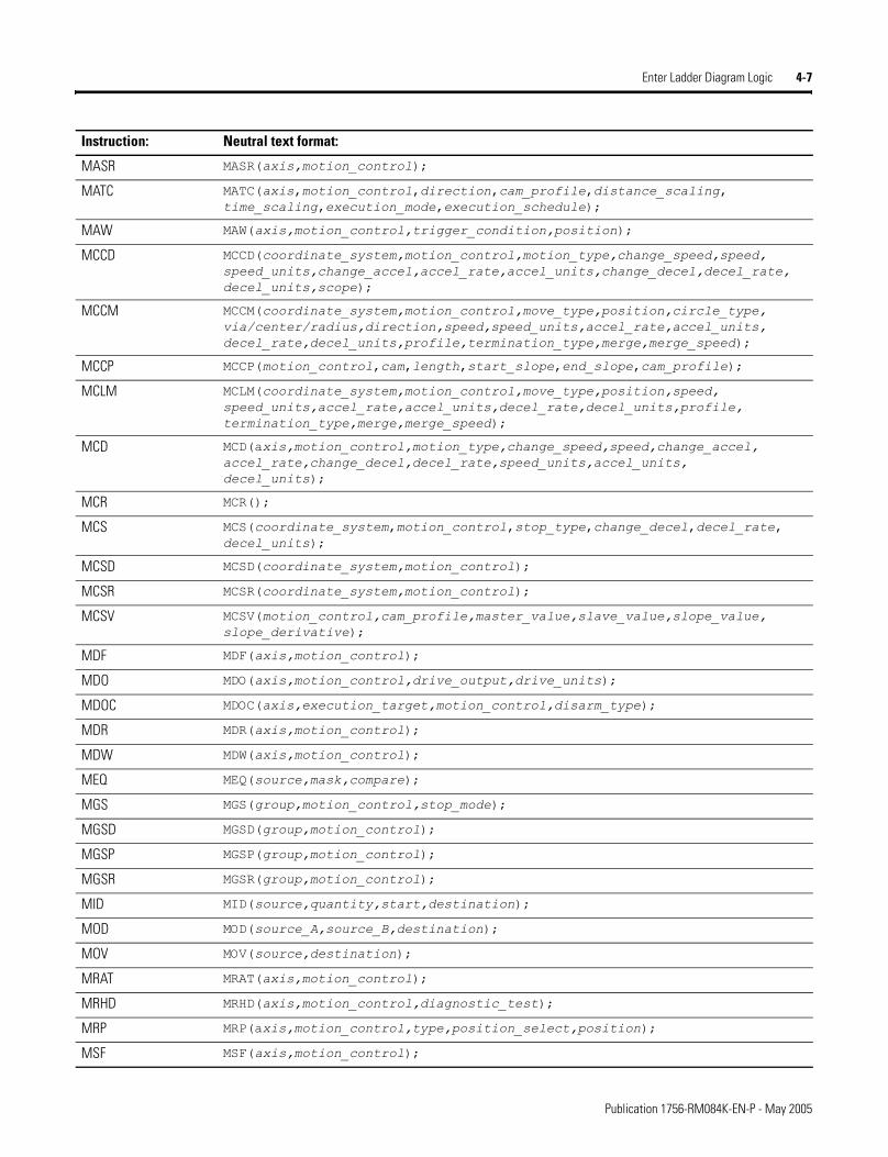
Enter Ladder Diagram Logic 4-7
MASR MASR(axis,motion_control);
MATC MATC(axis,motion_control,direction,cam_profile,distance_scaling, time_scaling,execution_mode,execution_schedule);
MAW MAW(axis,motion_control,trigger_condition,position);
MCCD MCCD(coordinate_system,motion_control,motion_type,change_speed,speed, speed_units,change_accel,accel_rate,accel_units,change_decel,decel_rate, decel_units,scope);
MCCM MCCM(coordinate_system,motion_control,move_type,position,circle_type, via/center/radius,direction,speed,speed_units,accel_rate,accel_units, decel_rate,decel_units,profile,termination_type,merge,merge_speed);
MCCP MCCP(motion_control,cam,length,start_slope,end_slope,cam_profile);
MCLM MCLM(coordinate_system,motion_control,move_type,position,speed, speed_units,accel_rate,accel_units,decel_rate,decel_units,profile, termination_type,merge,merge_speed);
MCD MCD(axis,motion_control,motion_type,change_speed,speed,change_accel, accel_rate,change_decel,decel_rate,speed_units,accel_units, decel_units);
MCR MCR();
MCS MCS(coordinate_system,motion_control,stop_type,change_decel,decel_rate, decel_units);
MCSD MCSD(coordinate_system,motion_control);
MCSR MCSR(coordinate_system,motion_control);
MCSV MCSV(motion_control,cam_profile,master_value,slave_value,slope_value, slope_derivative);
MDF MDF(axis,motion_control);
MDO MDO(axis,motion_control,drive_output,drive_units);
MDOC MDOC(axis,execution_target,motion_control,disarm_type);
MDR MDR(axis,motion_control);
MDW MDW(axis,motion_control);
MEQ MEQ(source,mask,compare);
MGS MGS(group,motion_control,stop_mode);
MGSD MGSD(group,motion_control);
MGSP MGSP(group,motion_control);
MGSR MGSR(group,motion_control);
MID MID(source,quantity,start,destination);
MOD MOD(source_A,source_B,destination);
MOV MOV(source,destination);
MRAT MRAT(axis,motion_control);
MRHD MRHD(axis,motion_control,diagnostic_test);
MRP MRP(axis,motion_control,type,position_select,position);
MSF MSF(axis,motion_control);
Instruction: Neutral text format:
Publication 1756-RM084K-EN-P - May 2005
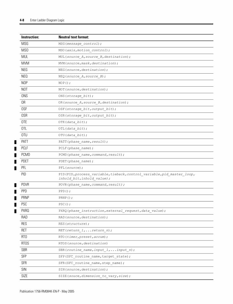
4-8 Enter Ladder Diagram Logic
MSG MSG(message_control);
MSO MSO(axis,motion_control);
MUL MUL(source_A,source_B,destination);
MVM MVM(source,mask,destination);
NEG NEG(source,destination);
NEQ NEQ(source_A,source_B);
NOP NOP();
NOT NOT(source,destination);
ONS ONS(storage_bit);
OR OR(source_A,source_B,destination);
OSF OSF(storage_bit,output_bit);
OSR OSR(storage_bit,output_bit);
OTE OTE(data_bit);
OTL OTL(data_bit);
OTU OTU(data_bit);
PATT PATT(phase_name,result);
PCLF PCLF(phase_name);
PCMD PCMD(phase_name,command,result);
PDET PDET(phase_name);
PFL PFL(source);
PID PID(PID,process_variable,tieback,control_variable,pid_master_loop, inhold_bit,inhold_value);
POVR POVR(phase_name,command,result);
PPD PPD();
PRNP PRNP();
PSC PSC();
PXRQ PXRQ(phase_instruction,external_request,data_value);
RAD RAD(source,destination);
RES RES(structure);
RET RET(return_1,...return_n);
RTO RTO(timer,preset,accum);
RTOS RTOS(source,destination)
SBR SBR(routine_name,input_1,...input_n);
SFP SFP(SFC_routine_name,target_state);
SFR SFR(SFC_routine_name,step_name);
SIN SIN(source,destination);
SIZE SIZE(souce,dimension_to_vary,size);
Instruction: Neutral text format:
Publication 1756-RM084K-EN-P - May 2005
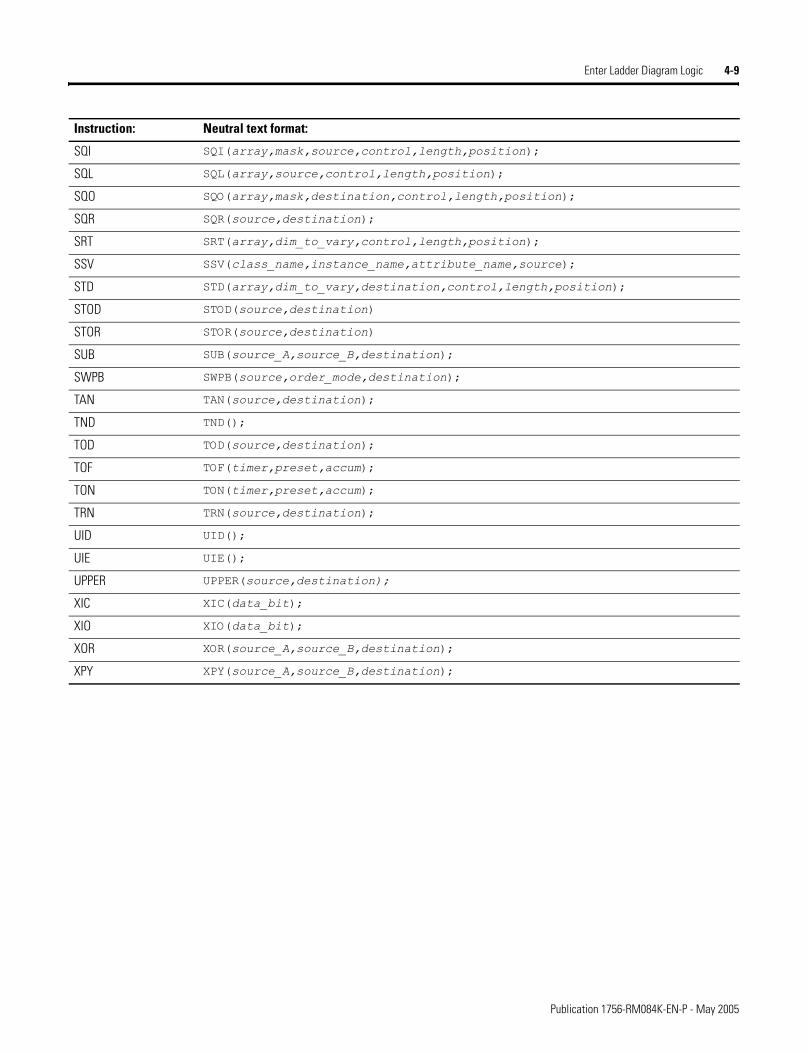
Enter Ladder Diagram Logic 4-9
SQI SQI(array,mask,source,control,length,position);
SQL SQL(array,source,control,length,position);
SQO SQO(array,mask,destination,control,length,position);
SQR SQR(source,destination);
SRT SRT(array,dim_to_vary,control,length,position);
SSV SSV(class_name,instance_name,attribute_name,source);
STD STD(array,dim_to_vary,destination,control,length,position);
STOD STOD(source,destination)
STOR STOR(source,destination)
SUB SUB(source_A,source_B,destination);
SWPB SWPB(source,order_mode,destination);
TAN TAN(source,destination);
TND TND();
TOD TOD(source,destination);
TOF TOF(timer,preset,accum);
TON TON(timer,preset,accum);
TRN TRN(source,destination);
UID UID();
UIE UIE();
UPPER UPPER(source,destination);
XIC XIC(data_bit);
XIO XIO(data_bit);
XOR XOR(source_A,source_B,destination);
XPY XPY(source_A,source_B,destination);
Instruction: Neutral text format:
Publication 1756-RM084K-EN-P - May 2005

4-10 Enter Ladder Diagram Logic
Notes:
Publication 1756-RM084K-EN-P - May 2005
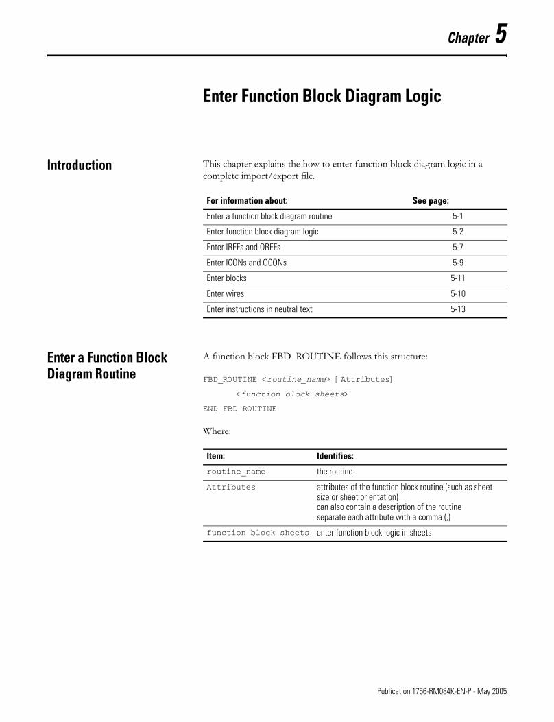
Chapter 5
Enter Function Block Diagram Logic
Introduction This chapter explains the how to enter function block diagram logic in a complete import/export file.
Enter a Function Block Diagram Routine
A function block FBD_ROUTINE follows this structure:
FBD_ROUTINE <routine_name> [Attributes]
<function block sheets>
END_FBD_ROUTINE
Where:
For information about: See page:
Enter a function block diagram routine 5-1
Enter function block diagram logic 5-2
Enter IREFs and OREFs 5-7
Enter ICONs and OCONs 5-9
Enter blocks 5-11
Enter wires 5-10
Enter instructions in neutral text 5-13
Item: Identifies:
routine_name the routine
Attributes attributes of the function block routine (such as sheet size or sheet orientation)can also contain a description of the routineseparate each attribute with a comma (,)
function block sheets enter function block logic in sheets
1 Publication 1756-RM084K-EN-P - May 2005
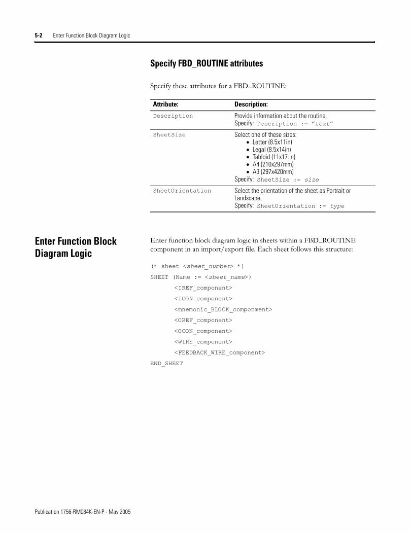
5-2 Enter Function Block Diagram Logic
Specify FBD_ROUTINE attributes
Specify these attributes for a FBD_ROUTINE:
Enter Function Block Diagram Logic
Enter function block diagram logic in sheets within a FBD_ROUTINE component in an import/export file. Each sheet follows this structure:
(* sheet <sheet_number> *)
SHEET (Name := <sheet_name>)
<IREF_component>
<ICON_component>
<mnemonic_BLOCK_componment>
<OREF_component>
<OCON_component>
<WIRE_component>
<FEEDBACK_WIRE_component>
END_SHEET
Attribute: Description:
Description Provide information about the routine.Specify: Description := �text�
SheetSize Select one of these sizes:• Letter (8.5x11in)• Legal (8.5x14in)• Tabloid (11x17.in)• A4 (210x297mm)• A3 (297x420mm)
Specify: SheetSize := size
SheetOrientation Select the orientation of the sheet as Portrait or Landscape.Specify: SheetOrientation := type
Publication 1756-RM084K-EN-P - May 2005
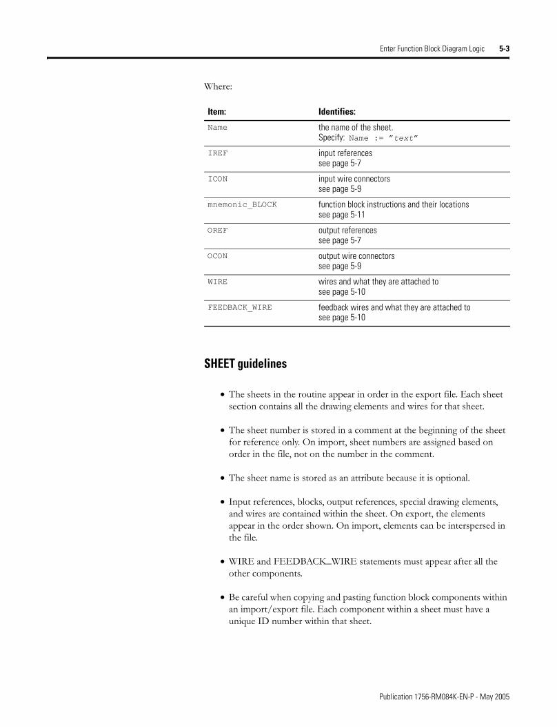
Enter Function Block Diagram Logic 5-3
Where:
SHEET guidelines
• The sheets in the routine appear in order in the export file. Each sheet section contains all the drawing elements and wires for that sheet.
• The sheet number is stored in a comment at the beginning of the sheet for reference only. On import, sheet numbers are assigned based on order in the file, not on the number in the comment.
• The sheet name is stored as an attribute because it is optional.
• Input references, blocks, output references, special drawing elements, and wires are contained within the sheet. On export, the elements appear in the order shown. On import, elements can be interspersed in the file.
• WIRE and FEEDBACK_WIRE statements must appear after all the other components.
• Be careful when copying and pasting function block components within an import/export file. Each component within a sheet must have a unique ID number within that sheet.
Item: Identifies:
Name the name of the sheet.Specify: Name := �text�
IREF input referencessee page 5-7
ICON input wire connectorssee page 5-9
mnemonic_BLOCK function block instructions and their locationssee page 5-11
OREF output referencessee page 5-7
OCON output wire connectorssee page 5-9
WIRE wires and what they are attached tosee page 5-10
FEEDBACK_WIRE feedback wires and what they are attached tosee page 5-10
Publication 1756-RM084K-EN-P - May 2005
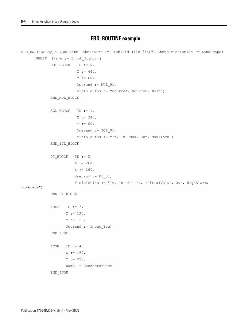
5-4 Enter Function Block Diagram Logic
FBD_ROUTINE example
FBD_ROUTINE My_FBD_Routine (SheetSize := "Tabloid (11x17in)", SheetOrientation := Landscape)
SHEET (Name := Input_Scaling)
MUL_BLOCK (ID := 0,
X := 440,
Y := 60,
Operand := MUL_01,
VisiblePins := "SourceA, SourceB, Dest")
END_MUL_BLOCK
SCL_BLOCK (ID := 1,
X := 240,
Y := 60,
Operand := SCL_01,
VisiblePins := "In, InEUMax, Out, MaxAlarm")
END_SCL_BLOCK
PI_BLOCK (ID := 2,
X := 260,
Y := 260,
Operand := PI_01,
VisiblePins := "In, Initialize, InitialValue, Out, HighAlarm, LowAlarm")
END_PI_BLOCK
IREF (ID := 3,
X := 120,
Y := 120,
Operand := Input_Tag)
END_IREF
ICON (ID := 4,
X := 160,
Y := 320,
Name := ConnectorName)
END_ICON
Publication 1756-RM084K-EN-P - May 2005
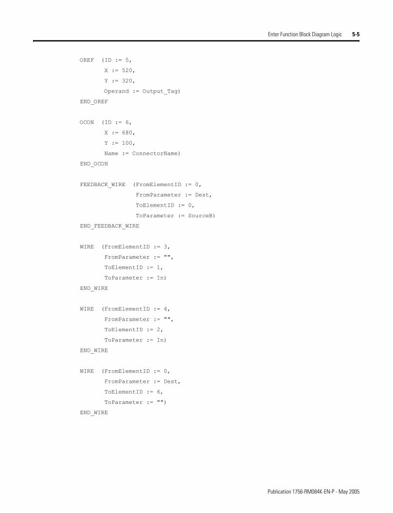
Enter Function Block Diagram Logic 5-5
OREF (ID := 5,
X := 520,
Y := 320,
Operand := Output_Tag)
END_OREF
OCON (ID := 6,
X := 680,
Y := 100,
Name := ConnectorName)
END_OCON
FEEDBACK_WIRE (FromElementID := 0,
FromParameter := Dest,
ToElementID := 0,
ToParameter := SourceB)
END_FEEDBACK_WIRE
WIRE (FromElementID := 3,
FromParameter := "",
ToElementID := 1,
ToParameter := In)
END_WIRE
WIRE (FromElementID := 4,
FromParameter := "",
ToElementID := 2,
ToParameter := In)
END_WIRE
WIRE (FromElementID := 0,
FromParameter := Dest,
ToElementID := 6,
ToParameter := "")
END_WIRE
Publication 1756-RM084K-EN-P - May 2005
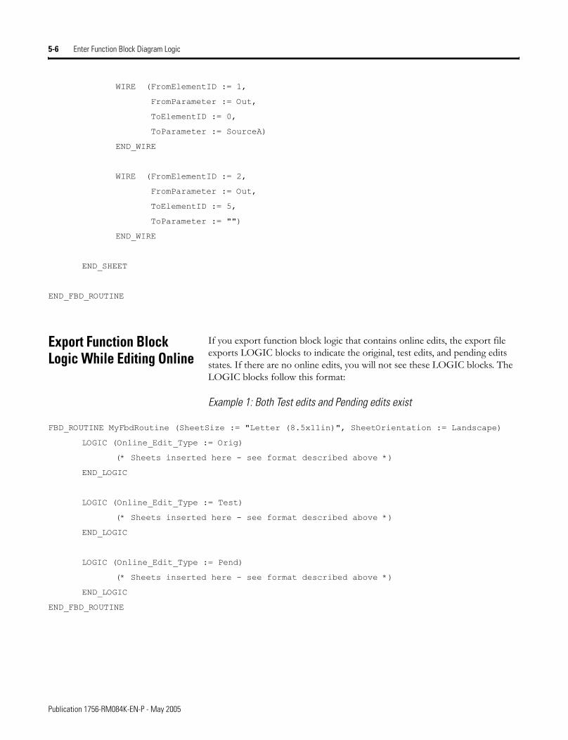
5-6 Enter Function Block Diagram Logic
WIRE (FromElementID := 1,
FromParameter := Out,
ToElementID := 0,
ToParameter := SourceA)
END_WIRE
WIRE (FromElementID := 2,
FromParameter := Out,
ToElementID := 5,
ToParameter := "")
END_WIRE
END_SHEET
END_FBD_ROUTINE
Export Function Block Logic While Editing Online
If you export function block logic that contains online edits, the export file exports LOGIC blocks to indicate the original, test edits, and pending edits states. If there are no online edits, you will not see these LOGIC blocks. The LOGIC blocks follow this format:
Example 1: Both Test edits and Pending edits exist
FBD_ROUTINE MyFbdRoutine (SheetSize := "Letter (8.5x11in)", SheetOrientation := Landscape)
LOGIC (Online_Edit_Type := Orig)
(* Sheets inserted here - see format described above *)
END_LOGIC
LOGIC (Online_Edit_Type := Test)
(* Sheets inserted here - see format described above *)
END_LOGIC
LOGIC (Online_Edit_Type := Pend)
(* Sheets inserted here - see format described above *)
END_LOGIC
END_FBD_ROUTINE
Publication 1756-RM084K-EN-P - May 2005
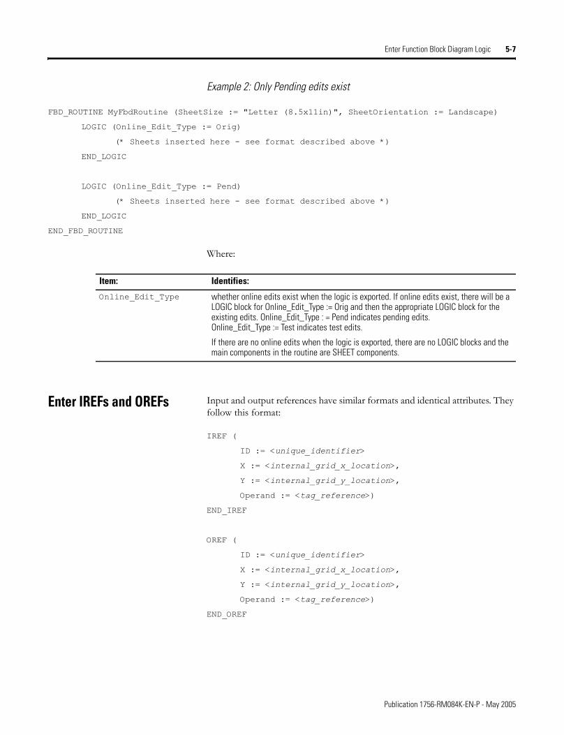
Enter Function Block Diagram Logic 5-7
Example 2: Only Pending edits exist
FBD_ROUTINE MyFbdRoutine (SheetSize := "Letter (8.5x11in)", SheetOrientation := Landscape)
LOGIC (Online_Edit_Type := Orig)
(* Sheets inserted here - see format described above *)
END_LOGIC
LOGIC (Online_Edit_Type := Pend)
(* Sheets inserted here - see format described above *)
END_LOGIC
END_FBD_ROUTINE
Where:
Enter IREFs and OREFs Input and output references have similar formats and identical attributes. They follow this format:
IREF (
ID := <unique_identifier>
X := <internal_grid_x_location>,
Y := <internal_grid_y_location>,
Operand := <tag_reference>)
END_IREF
OREF (
ID := <unique_identifier>
X := <internal_grid_x_location>,
Y := <internal_grid_y_location>,
Operand := <tag_reference>)
END_OREF
Item: Identifies:
Online_Edit_Type whether online edits exist when the logic is exported. If online edits exist, there will be a LOGIC block for Online_Edit_Type := Orig and then the appropriate LOGIC block for the existing edits. Online_Edit_Type : = Pend indicates pending edits. Online_Edit_Type := Test indicates test edits.
If there are no online edits when the logic is exported, there are no LOGIC blocks and the main components in the routine are SHEET components.
Publication 1756-RM084K-EN-P - May 2005
5-8 Enter Function Block Diagram Logic
Where:
IREF and OREF guidelines
• If the Operand is not a qualified tag or literal value, the IREF/OREF will not be verified.
• The X and Y grid locations are a relative position from the upper-left corner of the sheet. X is the horizontal position; Y is the vertical position.
IREF and OREF examples
IREF (ID := 8, X := 200, Y := 380, Operand := PMUL_InitVal)
END_IREF
OREF (ID := 9, X := 480, Y := 340, Operand := FB_PMUL)
END_OREF
Item: Identifies:
ID the IREF or OREF identifier; uniqueness is important for wiringenter unsigned, 32-bit integer valueSpecify: ID := �number�
X x-coordinates on internal gridenter unsigned, 32-bit integer valueSpecify: X := �number�
Y y-coordinates on internal gridenter unsigned, 32-bit integer valueSpecify: Y := �number�
Operand the reference (optional)enter tag or literal value for IREF; enter tag for OREFSpecify: Operand := �tag�
Publication 1756-RM084K-EN-P - May 2005
Enter Function Block Diagram Logic 5-9
Enter ICONs and OCONs Input and output wire connectors have similar formats and identical attributes. They follow this format:
ICON (ID := <unique_identifier>
X := <internal_grid_x_location>,
Y := <internal_grid_y_location>,
Name := <connector_name>)
END_ICON
OCON (ID := <unique_identifier>
X := <internal_grid_x_location>,
Y := <internal_grid_y_location>,
Name := <connector_name>)
END_OCON
Where:
ICON and OCON guidelines
• OCON connector names must be unique within a function block routine.
• Multiple ICON connector names can reference the same OCON connector name.
• ICONs and OCONs with unmatched or blank connector names will not be verified.
• The X and Y grid locations are a relative position from the upper-left corner of the sheet. X is the horizontal position; Y is the vertical position.
Item: Identifies:
ID the ICON or OCON identifier; uniqueness is important for wiringenter unsigned, 32-bit integer valueSpecify: ID := �number�
X x-coordinates on internal gridenter unsigned, 32-bit integer valueSpecify: X := �number�
Y y-coordinates on internal gridenter unsigned, 32-bit integer valueSpecify: Y := �number�
Name the name of the wire connector (optional)Specify: Name := �number�
Publication 1756-RM084K-EN-P - May 2005
5-10 Enter Function Block Diagram Logic
ICON and OCON examples
ICON (ID := 1, X := 140, Y := 300, Name := MyConnector)
END_ICON
OCON (ID := 4, X := 460, Y := 140, Name := MyConnector)
END_OCON
Enter Wires and Feedback Wires
The wire and feedback wire formats describe a wire by specifying what it is attached to at each end, which is always a pin on another drawing element. Wires and feedback wires follow this format:
WIRE
FromElementID := <indentifier_of_from_element>,
FromParameter := <name_of_output_pin>,
ToElementID := <indentifier_of_to_element>,
ToParameter := <name_of_input_pin>
END_WIRE
Where:
Item: Identifies:
FromElementID the source drawing elemententer unsigned, 32-bit integerSpecify: FromElementID := �number�
FromParameter the pin on the source drawing element
For: Enter:blocks parameter nameIREFs InICONs InSpecify: FromParameter := �pin�
ToElementID the destination drawing elemententer unsigned, 32-bit integerSpecify: ToElementID := �number�
ToParameter the pin on the destination drawing element
For: Enter:blocks parameter nameOREFs OutOCONs OutSpecify: ToParameter := �pin�
Publication 1756-RM084K-EN-P - May 2005
Enter Function Block Diagram Logic 5-11
WIRE guidelines
• Wires that are not correctly specified will not be imported.
• A feedback wire follows the same format as a wire. Just connect the source and destination elements to form a feedback.
WIRE example
WIRE (FromElementID := 11, FromParameter := "", ToElementID := 1, ToParameter := Initialize)
END_WIRE
Enter Blocks All function blocks follow this format:
mnemonic_BLOCK (
ID := <unique_identifier>
X := <internal_grid_x_location>,
Y := <internal_grid_y_location>,
Operand := <block_tag_reference>,
<Array_Name>Operand := <array_tag_reference>,
VisiblePins := �<parameter_name>, ��)
END_mnemonic_BLOCK
Publication 1756-RM084K-EN-P - May 2005
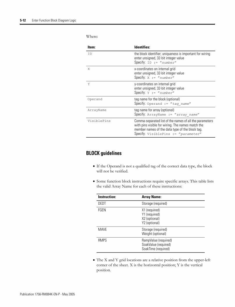
5-12 Enter Function Block Diagram Logic
Where:
BLOCK guidelines
• If the Operand is not a qualified tag of the correct data type, the block will not be verified.
• Some function block instructions require specific arrays. This table lists the valid Array Name for each of these instructions:
• The X and Y grid locations are a relative position from the upper-left corner of the sheet. X is the horizontal position; Y is the vertical position.
Item: Identifies:
ID the block identifier; uniqueness is important for wiringenter unsigned, 32-bit integer valueSpecify: ID := �number�
X x-coordinates on internal gridenter unsigned, 32-bit integer valueSpecify: X := �number�
Y y-coordinates on internal gridenter unsigned, 32-bit integer valueSpecify: Y := �number�
Operand tag name for the block (optional)Specify: Operand := �tag_name�
ArrayName tag name for array (optional)Specify: ArrayName := �array_name�
VisiblePins Comma-separated list of the names of all the parameters with pins visible for wiring. The names match the member names of the data type of the block tag. Specify: VisiblePins := �parameter�
Instruction: Array Name:
DEDT Storage (required)
FGEN X1 (required)Y1 (required)X2 (optional)Y2 (optional)
MAVE Storage (required)Weight (optional)
RMPS RampValue (required)SoakValue (required)SoakTime (required)
Publication 1756-RM084K-EN-P - May 2005
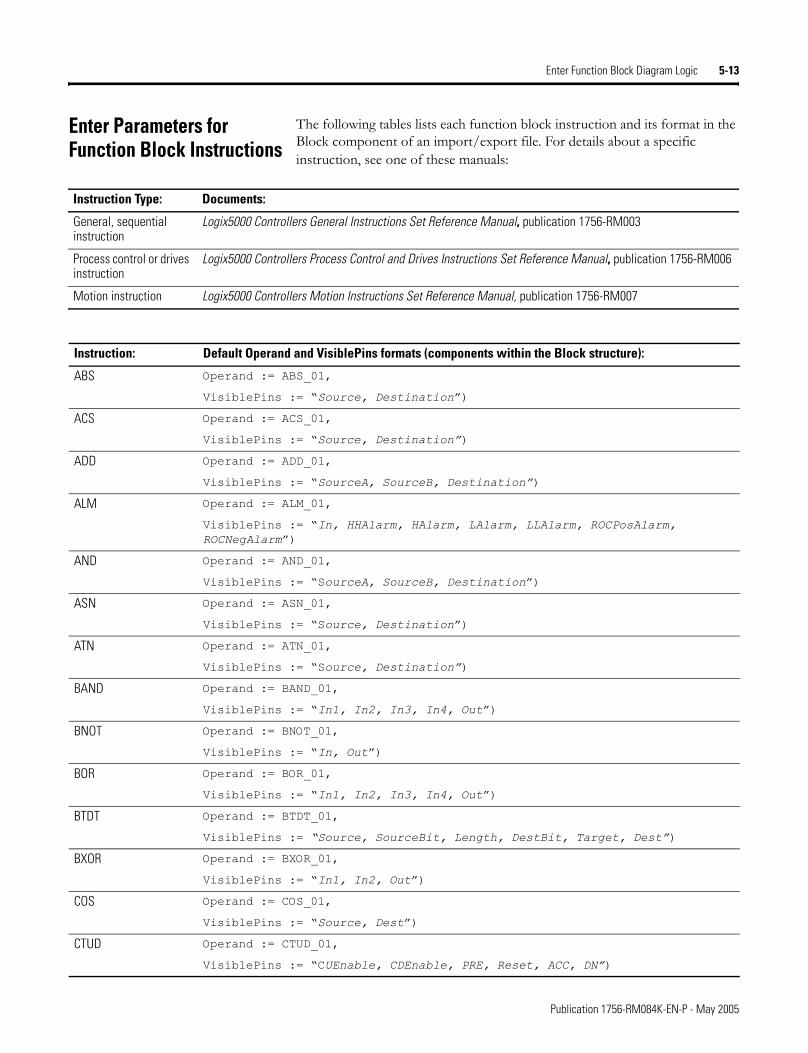
Enter Function Block Diagram Logic 5-13
Enter Parameters for Function Block Instructions
The following tables lists each function block instruction and its format in the Block component of an import/export file. For details about a specific instruction, see one of these manuals:
Instruction Type: Documents:
General, sequential instruction
Logix5000 Controllers General Instructions Set Reference Manual, publication 1756-RM003
Process control or drives instruction
Logix5000 Controllers Process Control and Drives Instructions Set Reference Manual, publication 1756-RM006
Motion instruction Logix5000 Controllers Motion Instructions Set Reference Manual, publication 1756-RM007
Instruction: Default Operand and VisiblePins formats (components within the Block structure):
ABS Operand := ABS_01,
VisiblePins := �Source, Destination�)
ACS Operand := ACS_01,
VisiblePins := �Source, Destination�)
ADD Operand := ADD_01,
VisiblePins := �SourceA, SourceB, Destination�)
ALM Operand := ALM_01,
VisiblePins := �In, HHAlarm, HAlarm, LAlarm, LLAlarm, ROCPosAlarm, ROCNegAlarm�)
AND Operand := AND_01,
VisiblePins := �SourceA, SourceB, Destination�)
ASN Operand := ASN_01,
VisiblePins := �Source, Destination�)
ATN Operand := ATN_01,
VisiblePins := �Source, Destination�)
BAND Operand := BAND_01,
VisiblePins := �In1, In2, In3, In4, Out�)
BNOT Operand := BNOT_01,
VisiblePins := �In, Out�)
BOR Operand := BOR_01,
VisiblePins := �In1, In2, In3, In4, Out�)
BTDT Operand := BTDT_01,
VisiblePins := �Source, SourceBit, Length, DestBit, Target, Dest�)
BXOR Operand := BXOR_01,
VisiblePins := �In1, In2, Out�)
COS Operand := COS_01,
VisiblePins := �Source, Dest�)
CTUD Operand := CTUD_01,
VisiblePins := �CUEnable, CDEnable, PRE, Reset, ACC, DN�)
Publication 1756-RM084K-EN-P - May 2005
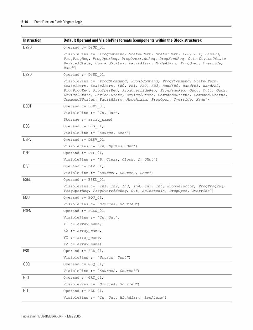
5-14 Enter Function Block Diagram Logic
D2SD Operand := D2SD_01,
VisiblePins := �ProgCommand, State0Perm, State1Perm, FB0, FB1, HandFB, ProgProgReq, ProgOperReq, ProgOverrideReq, ProgHandReq, Out, Device0State, Device1State, CommandStatus, FaultAlarm, ModeAlarm, ProgOper, Override, Hand�)
D3SD Operand := D3SD_01,
VisiblePins := �Prog0Command, Prog1Command, Prog2Command, State0Perm, State1Perm, State2Perm, FB0, FB1, FB2, FB3, HandFB0, HandFB1, HandFB2, ProgProgReq, ProgOperReq, ProgOverrideReq, ProgHandReq, Out0, Out1, Out2, Device0State, Device1State, Device2State, Command0Status, Command1Status, Command2Status, FaultAlarm, ModeAlarm, ProgOper, Override, Hand�)
DEDT Operand := DEDT_01,
VisiblePins := �In, Out�,
Storage := array_name)
DEG Operand := DEG_01,
VisiblePins := �Source, Dest�)
DERV Operand := DERV_01,
VisiblePins := �In, ByPass, Out�)
DFF Operand := DFF_01,
VisiblePins := �D, Clear, Clock, Q, QNot�)
DIV Operand := DIV_01,
VisiblePins := �SourceA, SourceB, Dest�)
ESEL Operand := ESEL_01,
VisiblePins := �In1, In2, In3, In4, In5, In6, ProgSelector, ProgProgReq, ProgOperReq, ProgOverrideReq, Out, SelectedIn, ProgOper, Override�)
EQU Operand := EQU_01,
VisiblePins := �SourceA, SourceB�)
FGEN Operand := FGEN_01,
VisiblePins := �In, Out�,
X1 := array_name,
X2 := array_name,
Y2 := array_name,
Y2 := array_name)
FRD Operand := FRD_01,
VisiblePins := �Source, Dest�)
GEQ Operand := GEQ_01,
VisiblePins := �SourceA, SourceB�)
GRT Operand := GRT_01,
VisiblePins := �SourceA, SourceB�)
HLL Operand := HLL_01,
VisiblePins := �In, Out, HighAlarm, LowAlarm�)
Instruction: Default Operand and VisiblePins formats (components within the Block structure):
Publication 1756-RM084K-EN-P - May 2005
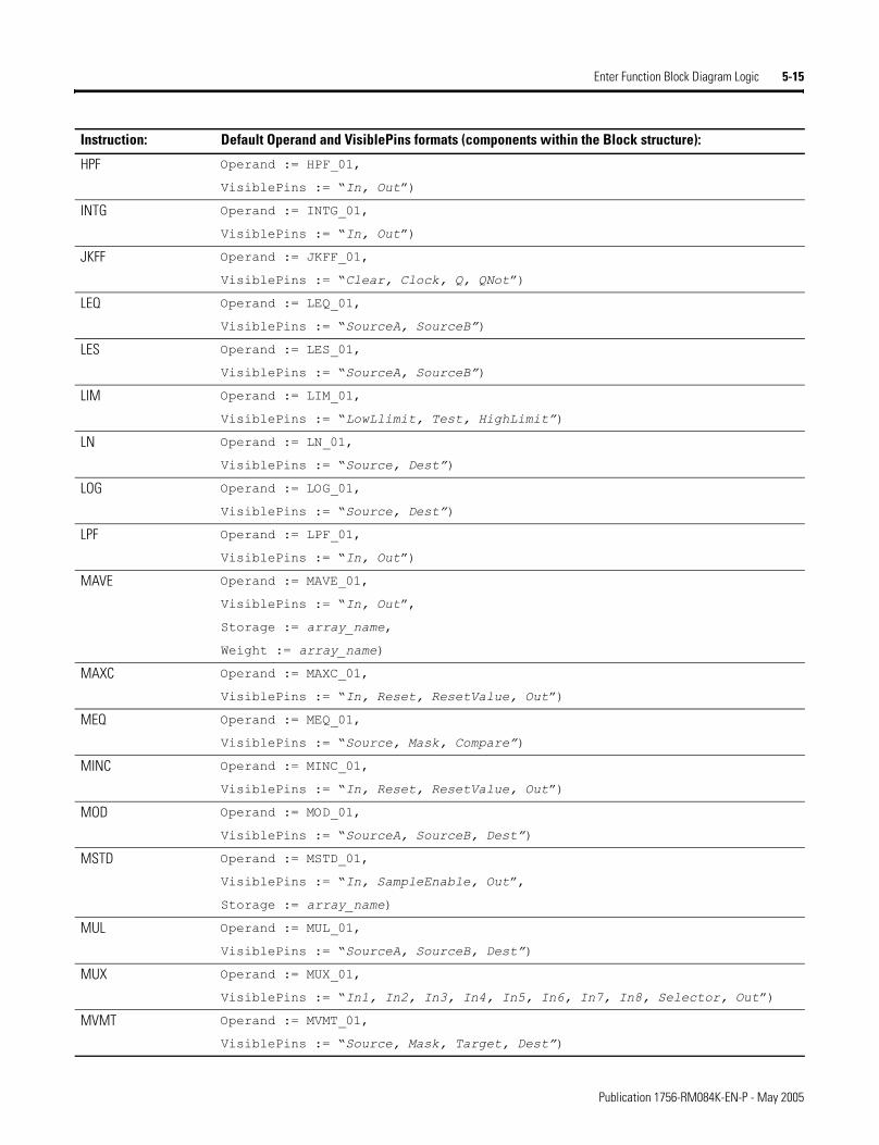
Enter Function Block Diagram Logic 5-15
HPF Operand := HPF_01,
VisiblePins := �In, Out�)
INTG Operand := INTG_01,
VisiblePins := �In, Out�)
JKFF Operand := JKFF_01,
VisiblePins := �Clear, Clock, Q, QNot�)
LEQ Operand := LEQ_01,
VisiblePins := �SourceA, SourceB�)
LES Operand := LES_01,
VisiblePins := �SourceA, SourceB�)
LIM Operand := LIM_01,
VisiblePins := �LowLlimit, Test, HighLimit�)
LN Operand := LN_01,
VisiblePins := �Source, Dest�)
LOG Operand := LOG_01,
VisiblePins := �Source, Dest�)
LPF Operand := LPF_01,
VisiblePins := �In, Out�)
MAVE Operand := MAVE_01,
VisiblePins := �In, Out�,
Storage := array_name,
Weight := array_name)
MAXC Operand := MAXC_01,
VisiblePins := �In, Reset, ResetValue, Out�)
MEQ Operand := MEQ_01,
VisiblePins := �Source, Mask, Compare�)
MINC Operand := MINC_01,
VisiblePins := �In, Reset, ResetValue, Out�)
MOD Operand := MOD_01,
VisiblePins := �SourceA, SourceB, Dest�)
MSTD Operand := MSTD_01,
VisiblePins := �In, SampleEnable, Out�,
Storage := array_name)
MUL Operand := MUL_01,
VisiblePins := �SourceA, SourceB, Dest�)
MUX Operand := MUX_01,
VisiblePins := �In1, In2, In3, In4, In5, In6, In7, In8, Selector, Out�)
MVMT Operand := MVMT_01,
VisiblePins := �Source, Mask, Target, Dest�)
Instruction: Default Operand and VisiblePins formats (components within the Block structure):
Publication 1756-RM084K-EN-P - May 2005
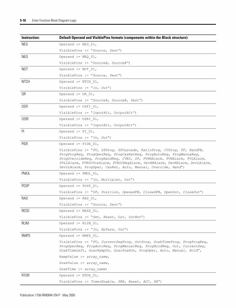
5-16 Enter Function Block Diagram Logic
NEG Operand := NEG_01,
VisiblePins := �Source, Dest�)
NEQ Operand := NEQ_01,
VisiblePins := �SourceA, SourceB�)
NOT Operand := NOT_01,
VisiblePins := �Source, Dest�)
NTCH Operand := NTCH_01,
VisiblePins := �In, Out�)
OR Operand := OR_01,
VisiblePins := �SourceA, SourceB, Dest�)
OSFI Operand := OSFI_01,
VisiblePins := �InputBit, OutputBit�)
OSRI Operand := OSRI_01,
VisiblePins := �InputBit, OutputBit�)
PI Operand := PI_01,
VisiblePins := �In, Out�)
PIDE Operand := PIDE_01,
VisiblePins := �PV, SPProg, SPCascade, RatioProg, CVProg, FF, HandFB, ProgProgReq, ProgOperReq, ProgCasRatReq, ProgAutoReq, ProgManuaReq, ProgOverrideReq, ProgHandReq, CVEU, SP, PVHHAlarm, PVHAlarm, PVLAlarm, PVLLAlarm, PVROCPosAlarm, PVROCNegAlarm, DevHHAlarm, DevHAlarm, DevLAlarm, DevLLAlarm, ProgOper, CasRat, Auto, Manual, Override, Hand�)
PMUL Operand := PMUL_01,
VisiblePins := �In, Multipler, Out�)
POSP Operand := POSP_01,
VisiblePins := �SP, Position, OpenedFB, ClosedFB, OpenOut, CloseOut�)
RAD Operand := RAD_01,
VisiblePins := �Source, Dest�)
RESD Operand := RESD_01,
VisiblePins := �Set, Reset, Out, OutNot�)
RLIM Operand := RLIM_01,
VisiblePins := �In, ByPass, Out�)
RMPS Operand := RMPS_01,
VisiblePins := �PV, CurrentSegProg, OutProg, SoakTimeProg, ProgProgReq, ProgOperReq, ProgAutoReq, ProgManualReq, ProgHoldReq, Out, CurrentSeg, SoakTimeLeft, GuarRampOn, GuarSoakOn, ProgOper, Auto, Manual, Hold�,
RampValue := array_name,
SoakValue := array_name,
SoakTime := array_name)
RTOR Operand := RTOR_01,
VisiblePins := TimerEnable, PRE, Reset, ACC, DN�)
Instruction: Default Operand and VisiblePins formats (components within the Block structure):
Publication 1756-RM084K-EN-P - May 2005
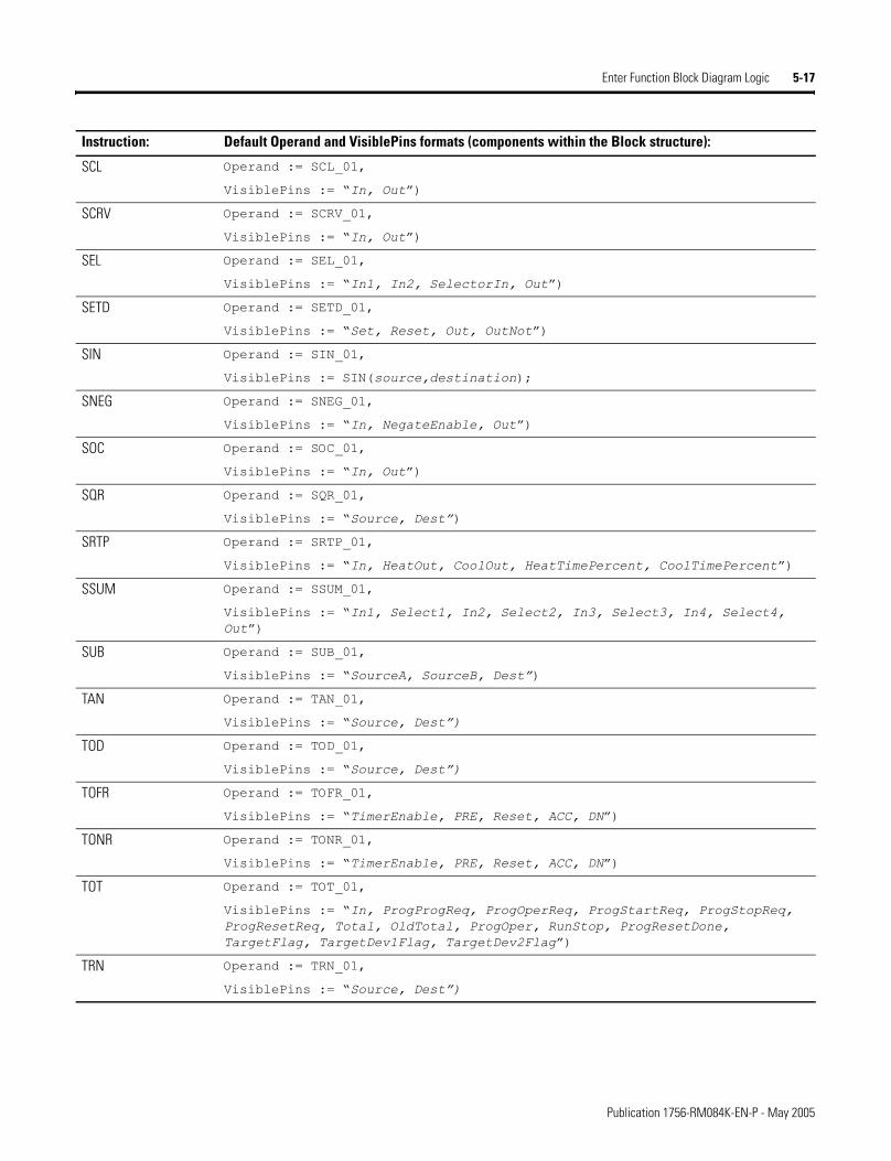
Enter Function Block Diagram Logic 5-17
SCL Operand := SCL_01,
VisiblePins := �In, Out�)
SCRV Operand := SCRV_01,
VisiblePins := �In, Out�)
SEL Operand := SEL_01,
VisiblePins := �In1, In2, SelectorIn, Out�)
SETD Operand := SETD_01,
VisiblePins := �Set, Reset, Out, OutNot�)
SIN Operand := SIN_01,
VisiblePins := SIN(source,destination);
SNEG Operand := SNEG_01,
VisiblePins := �In, NegateEnable, Out�)
SOC Operand := SOC_01,
VisiblePins := �In, Out�)
SQR Operand := SQR_01,
VisiblePins := �Source, Dest�)
SRTP Operand := SRTP_01,
VisiblePins := �In, HeatOut, CoolOut, HeatTimePercent, CoolTimePercent�)
SSUM Operand := SSUM_01,
VisiblePins := �In1, Select1, In2, Select2, In3, Select3, In4, Select4, Out�)
SUB Operand := SUB_01,
VisiblePins := �SourceA, SourceB, Dest�)
TAN Operand := TAN_01,
VisiblePins := �Source, Dest�)
TOD Operand := TOD_01,
VisiblePins := �Source, Dest�)
TOFR Operand := TOFR_01,
VisiblePins := �TimerEnable, PRE, Reset, ACC, DN�)
TONR Operand := TONR_01,
VisiblePins := �TimerEnable, PRE, Reset, ACC, DN�)
TOT Operand := TOT_01,
VisiblePins := �In, ProgProgReq, ProgOperReq, ProgStartReq, ProgStopReq, ProgResetReq, Total, OldTotal, ProgOper, RunStop, ProgResetDone, TargetFlag, TargetDev1Flag, TargetDev2Flag�)
TRN Operand := TRN_01,
VisiblePins := �Source, Dest�)
Instruction: Default Operand and VisiblePins formats (components within the Block structure):
Publication 1756-RM084K-EN-P - May 2005
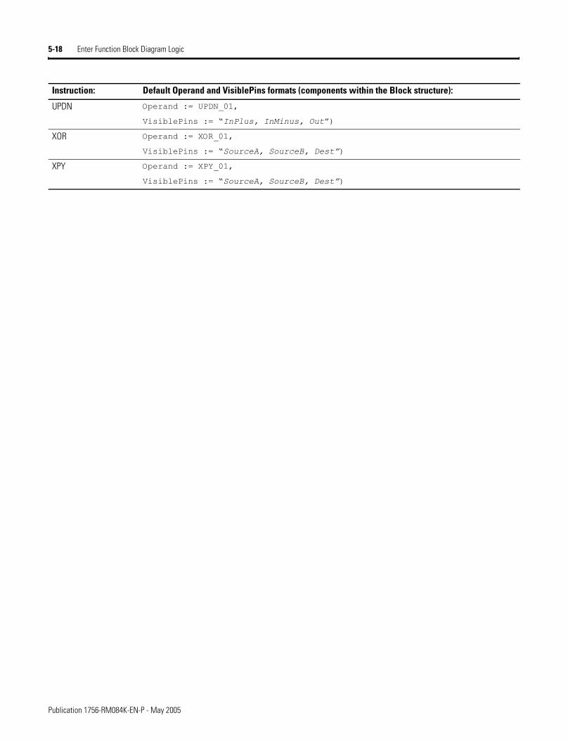
5-18 Enter Function Block Diagram Logic
UPDN Operand := UPDN_01,
VisiblePins := �InPlus, InMinus, Out�)
XOR Operand := XOR_01,
VisiblePins := �SourceA, SourceB, Dest�)
XPY Operand := XPY_01,
VisiblePins := �SourceA, SourceB, Dest�)
Instruction: Default Operand and VisiblePins formats (components within the Block structure):
Publication 1756-RM084K-EN-P - May 2005
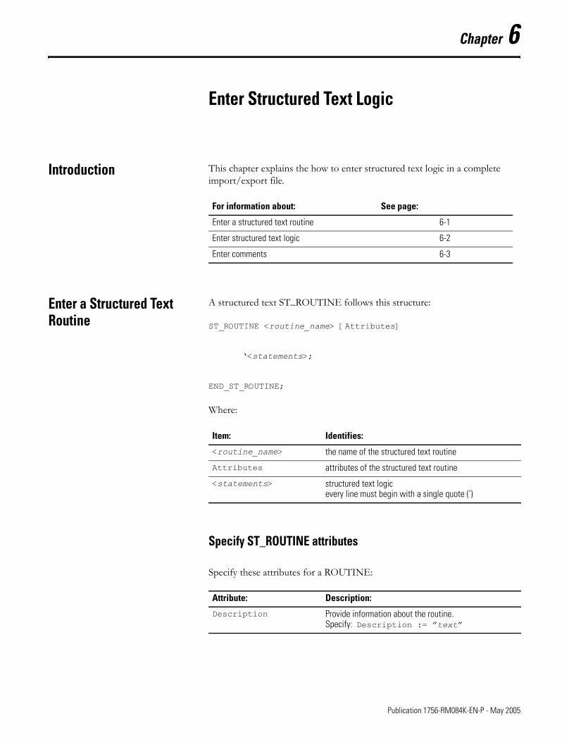
Chapter 6
Enter Structured Text Logic
Introduction This chapter explains the how to enter structured text logic in a complete import/export file.
Enter a Structured Text Routine
A structured text ST_ROUTINE follows this structure:
ST_ROUTINE <routine_name> [Attributes]
�<statements>;
END_ST_ROUTINE;
Where:
Specify ST_ROUTINE attributes
Specify these attributes for a ROUTINE:
For information about: See page:
Enter a structured text routine 6-1
Enter structured text logic 6-2
Enter comments 6-3
Item: Identifies:
<routine_name> the name of the structured text routine
Attributes attributes of the structured text routine
<statements> structured text logicevery line must begin with a single quote (‘)
Attribute: Description:
Description Provide information about the routine.Specify: Description := �text�
1 Publication 1756-RM084K-EN-P - May 2005
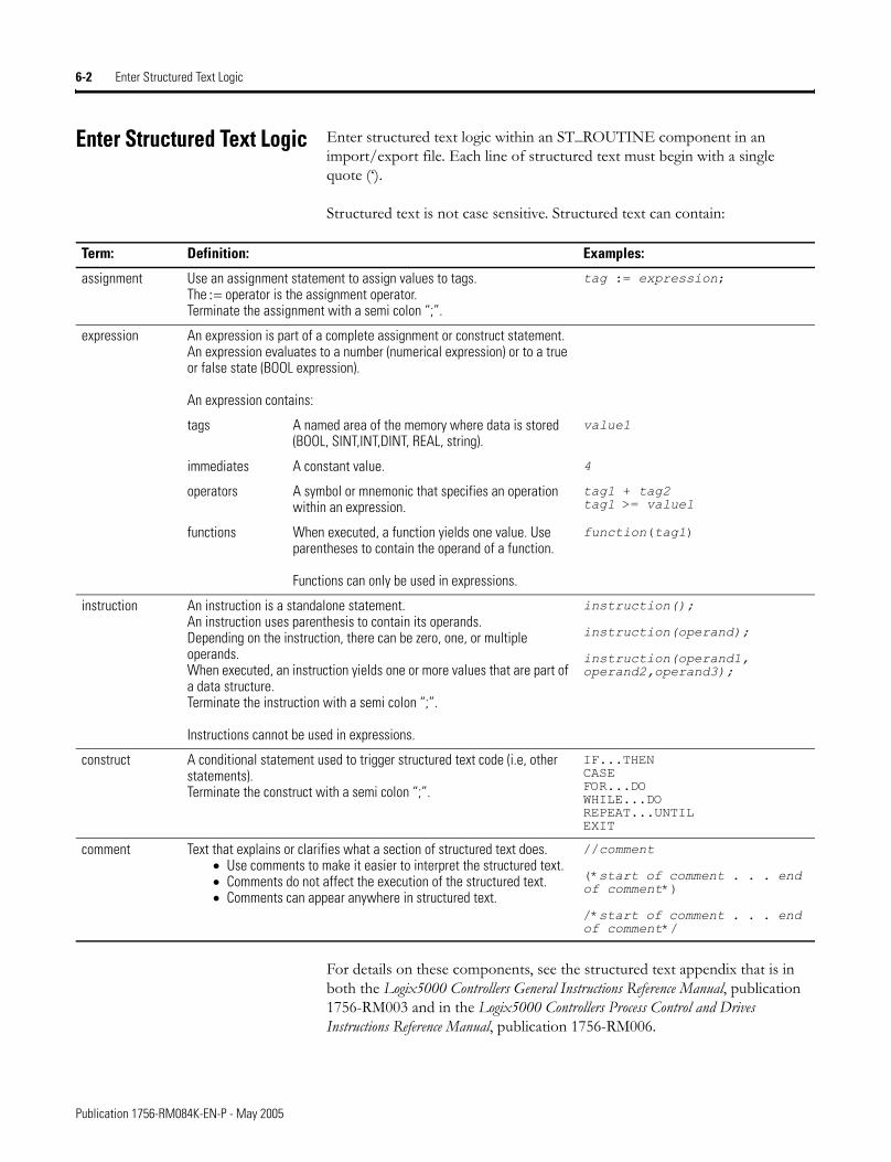
6-2 Enter Structured Text Logic
Enter Structured Text Logic Enter structured text logic within an ST_ROUTINE component in an import/export file. Each line of structured text must begin with a single quote (�).
Structured text is not case sensitive. Structured text can contain:
For details on these components, see the structured text appendix that is in both the Logix5000 Controllers General Instructions Reference Manual, publication 1756-RM003 and in the Logix5000 Controllers Process Control and Drives Instructions Reference Manual, publication 1756-RM006.
Term: Definition: Examples:
assignment Use an assignment statement to assign values to tags.The := operator is the assignment operator.Terminate the assignment with a semi colon “;”.
tag := expression;
expression An expression is part of a complete assignment or construct statement. An expression evaluates to a number (numerical expression) or to a true or false state (BOOL expression).
An expression contains:
tags A named area of the memory where data is stored (BOOL, SINT,INT,DINT, REAL, string).
value1
immediates A constant value. 4
operators A symbol or mnemonic that specifies an operation within an expression.
tag1 + tag2tag1 >= value1
functions When executed, a function yields one value. Use parentheses to contain the operand of a function.
Functions can only be used in expressions.
function(tag1)
instruction An instruction is a standalone statement.An instruction uses parenthesis to contain its operands.Depending on the instruction, there can be zero, one, or multiple operands.When executed, an instruction yields one or more values that are part of a data structure.Terminate the instruction with a semi colon “;”.
Instructions cannot be used in expressions.
instruction();
instruction(operand);
instruction(operand1, operand2,operand3);
construct A conditional statement used to trigger structured text code (i.e, other statements).Terminate the construct with a semi colon “;”.
IF...THENCASEFOR...DOWHILE...DOREPEAT...UNTILEXIT
comment Text that explains or clarifies what a section of structured text does. • Use comments to make it easier to interpret the structured text.• Comments do not affect the execution of the structured text.• Comments can appear anywhere in structured text.
//comment
(*start of comment . . . end of comment*)
/*start of comment . . . end of comment*/
Publication 1756-RM084K-EN-P - May 2005
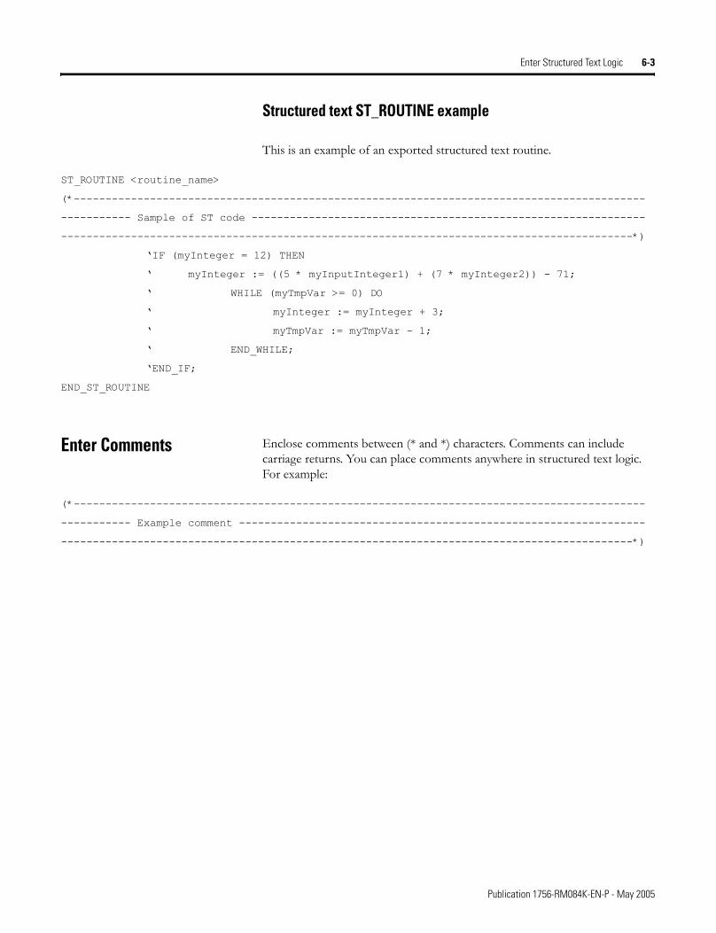
Enter Structured Text Logic 6-3
Structured text ST_ROUTINE example
This is an example of an exported structured text routine.
ST_ROUTINE <routine_name>
(*------------------------------------------------------------------------------------------
----------- Sample of ST code --------------------------------------------------------------
------------------------------------------------------------------------------------------*)
�IF (myInteger = 12) THEN
� myInteger := ((5 * myInputInteger1) + (7 * myInteger2)) - 71;
� WHILE (myTmpVar >= 0) DO
� myInteger := myInteger + 3;
� myTmpVar := myTmpVar - 1;
� END_WHILE;
�END_IF;
END_ST_ROUTINE
Enter Comments Enclose comments between (* and *) characters. Comments can include carriage returns. You can place comments anywhere in structured text logic. For example:
(*------------------------------------------------------------------------------------------
----------- Example comment ----------------------------------------------------------------
------------------------------------------------------------------------------------------*)
Publication 1756-RM084K-EN-P - May 2005
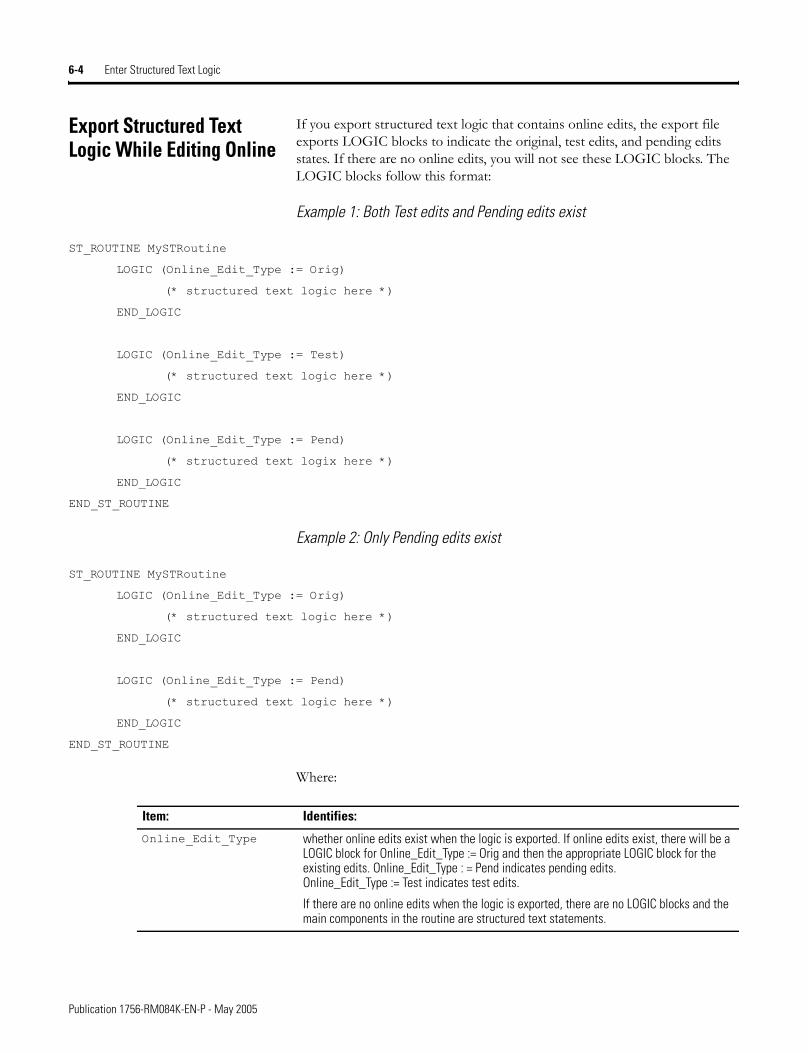
6-4 Enter Structured Text Logic
Export Structured Text Logic While Editing Online
If you export structured text logic that contains online edits, the export file exports LOGIC blocks to indicate the original, test edits, and pending edits states. If there are no online edits, you will not see these LOGIC blocks. The LOGIC blocks follow this format:
Example 1: Both Test edits and Pending edits exist
ST_ROUTINE MySTRoutine
LOGIC (Online_Edit_Type := Orig)
(* structured text logic here *)
END_LOGIC
LOGIC (Online_Edit_Type := Test)
(* structured text logic here *)
END_LOGIC
LOGIC (Online_Edit_Type := Pend)
(* structured text logix here *)
END_LOGIC
END_ST_ROUTINE
Example 2: Only Pending edits exist
ST_ROUTINE MySTRoutine
LOGIC (Online_Edit_Type := Orig)
(* structured text logic here *)
END_LOGIC
LOGIC (Online_Edit_Type := Pend)
(* structured text logic here *)
END_LOGIC
END_ST_ROUTINE
Where:
Item: Identifies:
Online_Edit_Type whether online edits exist when the logic is exported. If online edits exist, there will be a LOGIC block for Online_Edit_Type := Orig and then the appropriate LOGIC block for the existing edits. Online_Edit_Type : = Pend indicates pending edits. Online_Edit_Type := Test indicates test edits.
If there are no online edits when the logic is exported, there are no LOGIC blocks and the main components in the routine are structured text statements.
Publication 1756-RM084K-EN-P - May 2005
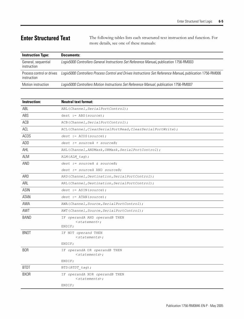
Enter Structured Text Logic 6-5
Enter Structured Text The following tables lists each structured text instruction and function. For more details, see one of these manuals:
Instruction Type: Documents:
General, sequential instruction
Logix5000 Controllers General Instructions Set Reference Manual, publication 1756-RM003
Process control or drives instruction
Logix5000 Controllers Process Control and Drives Instructions Set Reference Manual, publication 1756-RM006
Motion instruction Logix5000 Controllers Motion Instructions Set Reference Manual, publication 1756-RM007
Instruction: Neutral text format:
ABL ABL(Channel,SerialPortControl);
ABS dest := ABS(source);
ACB ACB(Channel,SerialPortControl);
ACL ACL(Channel,ClearSerialPortRead,ClearSerialPortWrite);
ACOS dest := ACOS(source);
ADD dest := sourceA + sourceB;
AHL AHL(Channel,ANDMask,ORMask,SerialPortControl);
ALM ALM(ALM_tag);
AND dest := sourceA & sourceB;
dest := sourceA AND sourceB;
ARD ARD(Channel,Destination,SerialPortControl);
ARL ARL(Channel,Destination,SerialPortControl);
ASIN dest := ASIN(source);
ATAN dest := ATAN(source);
AWA AWA(Channel,Source,SerialPortControl);
AWT AWT(Channel,Source,SerialPortControl);
BAND IF operandA AND operandB THEN<statement>;
ENDIF;
BNOT IF NOT operand THEN<statements>;
ENDIF;
BOR IF operandA OR operandB THEN<statements>;
ENDIF;
BTDT BTD(BTDT_tag);
BXOR IF operandA XOR operandB THEN<statements>;
ENDIF;
Publication 1756-RM084K-EN-P - May 2005
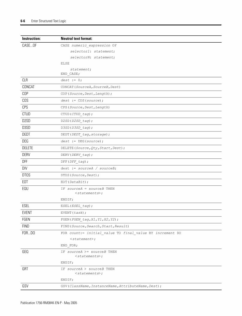
6-6 Enter Structured Text Logic
CASE...OF CASE numeric_expression OF
selector1: statement;
selectorN: statement;
ELSE
statement;END_CASE;
CLR dest := 0;
CONCAT CONCAT(SourceA,SourceB,Dest)
COP COP(Source,Dest,Length);
COS dest := COS(source);
CPS CPS(Source,Dest,Length)
CTUD CTUD(CTUD_tag);
D2SD D2SD(D2SD_tag);
D3SD D3SD(D3SD_tag);
DEDT DEDT(DEDT_tag,storage);
DEG dest := DEG(source);
DELETE DELETE(Source,Qty,Start,Dest);
DERV DERV(DERV_tag);
DFF DFF(DFF_tag);
DIV dest := sourceA / sourceB;
DTOS DTOS(Source,Dest);
EOT EOT(DataBit);
EQU IF sourceA = sourceB THEN<statements>;
ENDIF;
ESEL ESEL(ESEL_tag);
EVENT EVENT(task);
FGEN FGEN(FGEN_tag,X1,Y1,X2,Y2);
FIND FIND(Source,Search,Start,Result)
FOR...DO FOR count:= initial_value TO final_value BY increment DO
<statement>;
END_FOR;
GEQ IF sourceA >= sourceB THEN<statements>;
ENDIF;
GRT IF sourceA > sourceB THEN<statements>;
ENDIF;
GSV GSV(ClassName,InstanceName,AttributeName,Dest);
Instruction: Neutral text format:
Publication 1756-RM084K-EN-P - May 2005
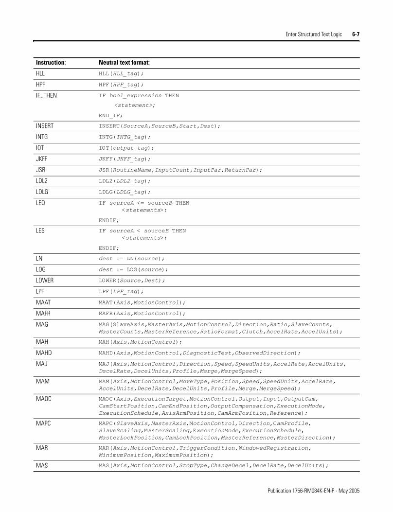
Enter Structured Text Logic 6-7
HLL HLL(HLL_tag);
HPF HPF(HPF_tag);
IF...THEN IF bool_expression THEN
<statement>;
END_IF;
INSERT INSERT(SourceA,SourceB,Start,Dest);
INTG INTG(INTG_tag);
IOT IOT(output_tag);
JKFF JKFF(JKFF_tag);
JSR JSR(RoutineName,InputCount,InputPar,ReturnPar);
LDL2 LDL2(LDL2_tag);
LDLG LDLG(LDLG_tag);
LEQ IF sourceA <= sourceB THEN<statements>;
ENDIF;
LES IF sourceA < sourceB THEN<statements>;
ENDIF;
LN dest := LN(source);
LOG dest := LOG(source);
LOWER LOWER(Source,Dest);
LPF LPF(LPF_tag);
MAAT MAAT(Axis,MotionControl);
MAFR MAFR(Axis,MotionControl);
MAG MAG(SlaveAxis,MasterAxis,MotionControl,Direction,Ratio,SlaveCounts, MasterCounts,MasterReference,RatioFormat,Clutch,AccelRate,AccelUnits);
MAH MAH(Axis,MotionControl);
MAHD MAHD(Axis,MotionControl,DiagnosticTest,ObservedDirection);
MAJ MAJ(Axis,MotionControl,Direction,Speed,SpeedUnits,AccelRate,AccelUnits, DecelRate,DecelUnits,Profile,Merge,MergeSpeed);
MAM MAM(Axis,MotionControl,MoveType,Position,Speed,SpeedUnits,AccelRate, AccelUnits,DecelRate,DecelUnits,Profile,Merge,MergeSpeed);
MAOC MAOC(Axis,ExecutionTarget,MotionControl,Output,Input,OutputCam, CamStartPosition,CamEndPosition,OutputCompensation,ExecutionMode, ExecutionSchedule,AxisArmPosition,CamArmPosition,Reference);
MAPC MAPC(SlaveAxis,MasterAxis,MotionControl,Direction,CamProfile, SlaveScaling,MasterScaling,ExecutionMode,ExecutionSchedule, MasterLockPosition,CamLockPosition,MasterReference,MasterDirection);
MAR MAR(Axis,MotionControl,TriggerCondition,WindowedRegistration, MinimumPosition,MaximumPosition);
MAS MAS(Axis,MotionControl,StopType,ChangeDecel,DecelRate,DecelUnits);
Instruction: Neutral text format:
Publication 1756-RM084K-EN-P - May 2005
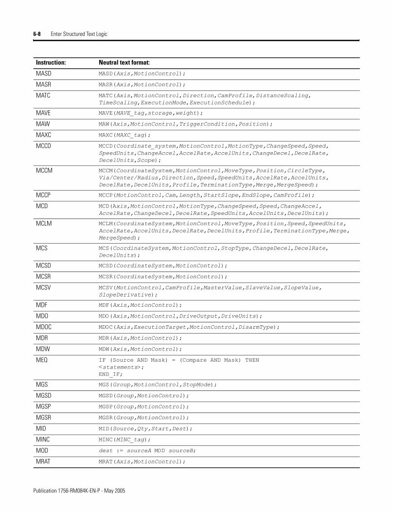
6-8 Enter Structured Text Logic
MASD MASD(Axis,MotionControl);
MASR MASR(Axis,MotionControl);
MATC MATC(Axis,MotionControl,Direction,CamProfile,DistanceScaling, TimeScaling,ExecutionMode,ExecutionSchedule);
MAVE MAVE(MAVE_tag,storage,weight);
MAW MAW(Axis,MotionControl,TriggerCondition,Position);
MAXC MAXC(MAXC_tag);
MCCD MCCD(Coordinate_system,MotionControl,MotionType,ChangeSpeed,Speed, SpeedUnits,ChangeAccel,AccelRate,AccelUnits,ChangeDecel,DecelRate, DecelUnits,Scope);
MCCM MCCM(CoordinateSystem,MotionControl,MoveType,Position,CircleType, Via/Center/Radius,Direction,Speed,SpeedUnits,AccelRate,AccelUnits, DecelRate,DecelUnits,Profile,TerminationType,Merge,MergeSpeed);
MCCP MCCP(MotionControl,Cam,Length,StartSlope,EndSlope,CamProfile);
MCD MCD(Axis,MotionControl,MotionType,ChangeSpeed,Speed,ChangeAccel, AccelRate,ChangeDecel,DecelRate,SpeedUnits,AccelUnits,DecelUnits);
MCLM MCLM(CoordinateSystem,MotionControl,MoveType,Position,Speed,SpeedUnits, AccelRate,AccelUnits,DecelRate,DecelUnits,Profile,TerminationType,Merge, MergeSpeed);
MCS MCS(CoordinateSystem,MotionControl,StopType,ChangeDecel,DecelRate, DecelUnits);
MCSD MCSD(CoordinateSystem,MotionControl);
MCSR MCSR(CoordinateSystem,MotionControl);
MCSV MCSV(MotionControl,CamProfile,MasterValue,SlaveValue,SlopeValue, SlopeDerivative);
MDF MDF(Axis,MotionControl);
MDO MDO(Axis,MotionControl,DriveOutput,DriveUnits);
MDOC MDOC(Axis,ExecutionTarget,MotionControl,DisarmType);
MDR MDR(Axis,MotionControl);
MDW MDW(Axis,MotionControl);
MEQ IF (Source AND Mask) = (Compare AND Mask) THEN<statements>;END_IF;
MGS MGS(Group,MotionControl,StopMode);
MGSD MGSD(Group,MotionControl);
MGSP MGSP(Group,MotionControl);
MGSR MGSR(Group,MotionControl);
MID MID(Source,Qty,Start,Dest);
MINC MINC(MINC_tag);
MOD dest := sourceA MOD sourceB;
MRAT MRAT(Axis,MotionControl);
Instruction: Neutral text format:
Publication 1756-RM084K-EN-P - May 2005
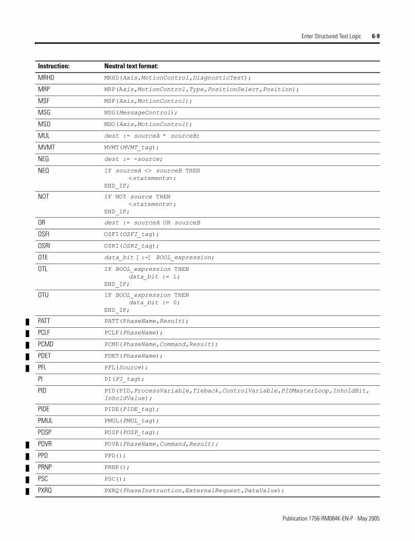
Enter Structured Text Logic 6-9
MRHD MRHD(Axis,MotionControl,DiagnosticTest);
MRP MRP(Axis,MotionControl,Type,PositionSelect,Position);
MSF MSF(Axis,MotionControl);
MSG MSG(MessageControl);
MSO MSO(Axis,MotionControl);
MUL dest := sourceA * sourceB;
MVMT MVMT(MVMT_tag);
NEG dest := -source;
NEQ IF sourceA <> sourceB THEN<statements>;
END_IF;
NOT IF NOT source THEN<statements>;
END_IF;
OR dest := sourceA OR sourceB
OSFI OSFI(OSFI_tag);
OSRI OSRI(OSRI_tag);
OTE data_bit [:=] BOOL_expression;
OTL IF BOOL_expression THENdata_bit := 1;
END_IF;
OTU IF BOOL_expression THENdata_bit := 0;
END_IF;
PATT PATT(PhaseName,Result);
PCLF PCLF(PhaseName);
PCMD PCMD(PhaseName,Command,Result);
PDET PDET(PhaseName);
PFL PFL(Source);
PI PI(PI_tag);
PID PID(PID,ProcessVariable,Tieback,ControlVariable,PIDMasterLoop,InholdBit, InholdValue);
PIDE PIDE(PIDE_tag);
PMUL PMUL(PMUL_tag);
POSP POSP(POSP_tag);
POVR POVR(PhaseName,Command,Result);
PPD PPD();
PRNP PRNP();
PSC PSC();
PXRQ PXRQ(PhaseInstruction,ExternalRequest,DataValue);
Instruction: Neutral text format:
Publication 1756-RM084K-EN-P - May 2005
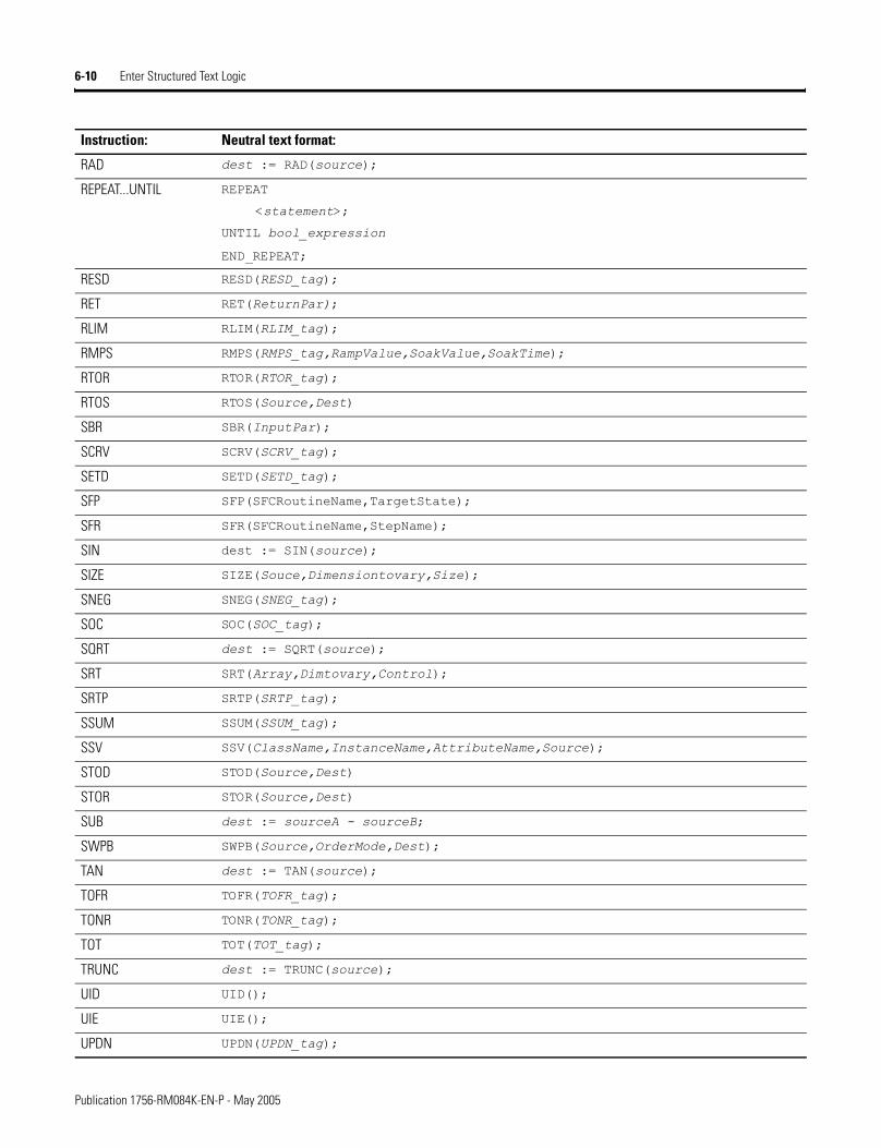
6-10 Enter Structured Text Logic
RAD dest := RAD(source);
REPEAT...UNTIL REPEAT
<statement>;
UNTIL bool_expression
END_REPEAT;
RESD RESD(RESD_tag);
RET RET(ReturnPar);
RLIM RLIM(RLIM_tag);
RMPS RMPS(RMPS_tag,RampValue,SoakValue,SoakTime);
RTOR RTOR(RTOR_tag);
RTOS RTOS(Source,Dest)
SBR SBR(InputPar);
SCRV SCRV(SCRV_tag);
SETD SETD(SETD_tag);
SFP SFP(SFCRoutineName,TargetState);
SFR SFR(SFCRoutineName,StepName);
SIN dest := SIN(source);
SIZE SIZE(Souce,Dimensiontovary,Size);
SNEG SNEG(SNEG_tag);
SOC SOC(SOC_tag);
SQRT dest := SQRT(source);
SRT SRT(Array,Dimtovary,Control);
SRTP SRTP(SRTP_tag);
SSUM SSUM(SSUM_tag);
SSV SSV(ClassName,InstanceName,AttributeName,Source);
STOD STOD(Source,Dest)
STOR STOR(Source,Dest)
SUB dest := sourceA - sourceB;
SWPB SWPB(Source,OrderMode,Dest);
TAN dest := TAN(source);
TOFR TOFR(TOFR_tag);
TONR TONR(TONR_tag);
TOT TOT(TOT_tag);
TRUNC dest := TRUNC(source);
UID UID();
UIE UIE();
UPDN UPDN(UPDN_tag);
Instruction: Neutral text format:
Publication 1756-RM084K-EN-P - May 2005
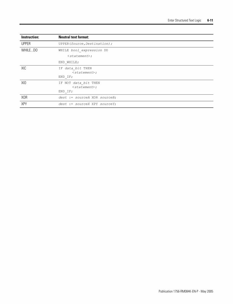
Enter Structured Text Logic 6-11
UPPER UPPER(Source,Destination);
WHILE...DO WHILE bool_expression DO
<statement>;
END_WHILE;
XIC IF data_bit THEN<statement>;
END_IF;
XIO IF NOT data_bit THEN<statement>;
END_IF;
XOR dest := sourceA XOR sourceB;
XPY dest := sourceX XPY sourceY;
Instruction: Neutral text format:
Publication 1756-RM084K-EN-P - May 2005

6-12 Enter Structured Text Logic
Notes:
Publication 1756-RM084K-EN-P - May 2005
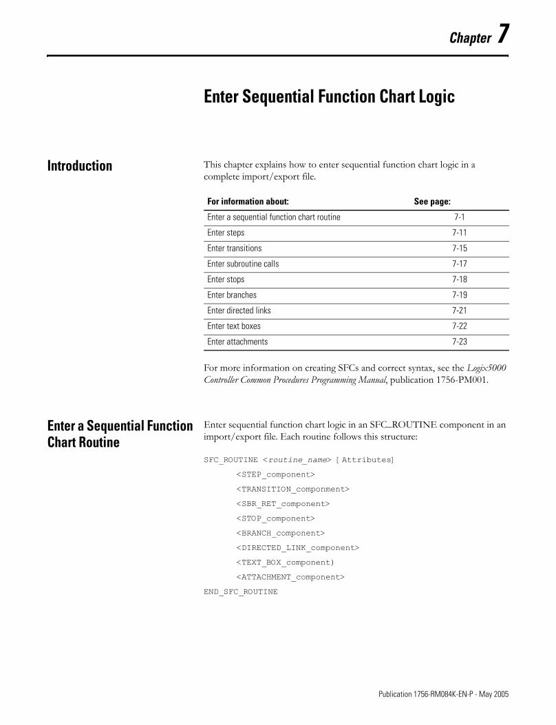
Chapter 7
Enter Sequential Function Chart Logic
Introduction This chapter explains how to enter sequential function chart logic in a complete import/export file.
For more information on creating SFCs and correct syntax, see the Logix5000 Controller Common Procedures Programming Manual, publication 1756-PM001.
Enter a Sequential Function Chart Routine
Enter sequential function chart logic in an SFC_ROUTINE component in an import/export file. Each routine follows this structure:
SFC_ROUTINE <routine_name> [Attributes]
<STEP_component>
<TRANSITION_componment>
<SBR_RET_component>
<STOP_component>
<BRANCH_component>
<DIRECTED_LINK_component>
<TEXT_BOX_component)
<ATTACHMENT_component>
END_SFC_ROUTINE
For information about: See page:
Enter a sequential function chart routine 7-1
Enter steps 7-11
Enter transitions 7-15
Enter subroutine calls 7-17
Enter stops 7-18
Enter branches 7-19
Enter directed links 7-21
Enter text boxes 7-22
Enter attachments 7-23
1 Publication 1756-RM084K-EN-P - May 2005
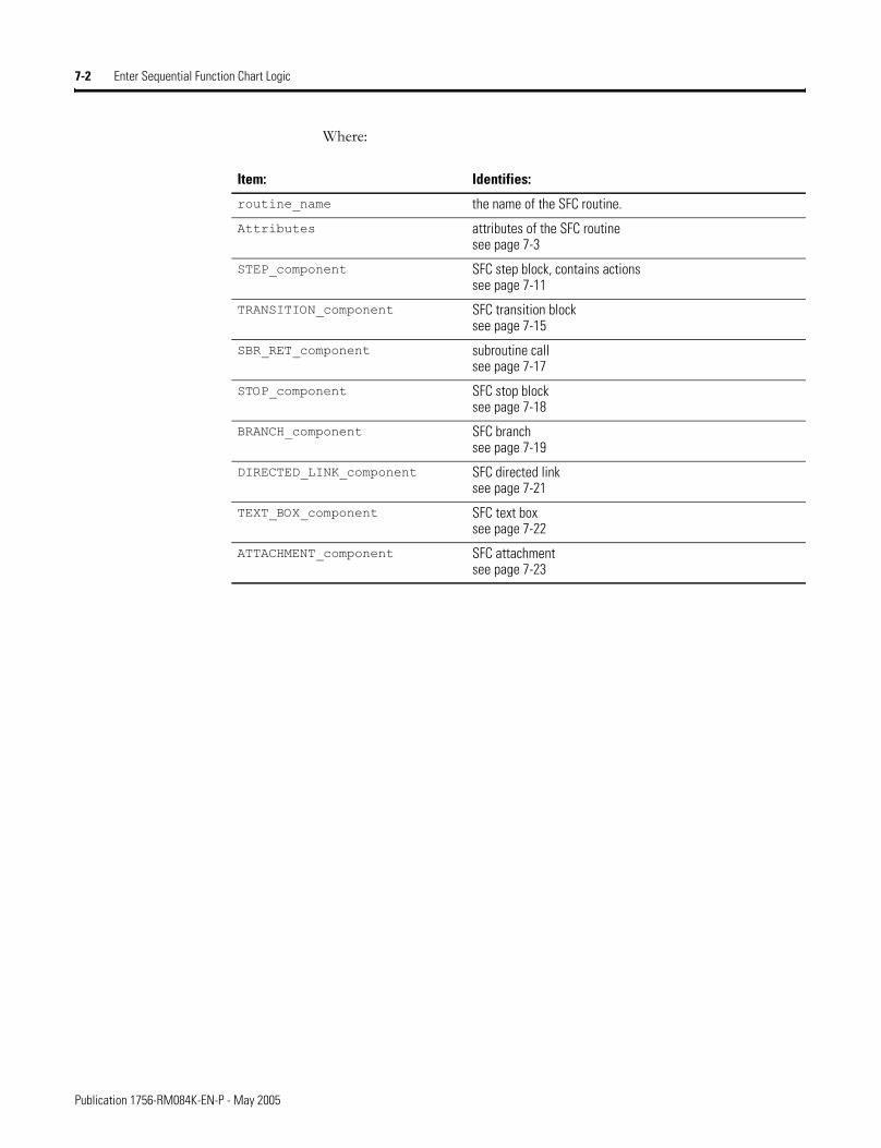
7-2 Enter Sequential Function Chart Logic
Where:
Item: Identifies:
routine_name the name of the SFC routine.
Attributes attributes of the SFC routinesee page 7-3
STEP_component SFC step block, contains actionssee page 7-11
TRANSITION_component SFC transition blocksee page 7-15
SBR_RET_component subroutine callsee page 7-17
STOP_component SFC stop blocksee page 7-18
BRANCH_component SFC branchsee page 7-19
DIRECTED_LINK_component SFC directed linksee page 7-21
TEXT_BOX_component SFC text boxsee page 7-22
ATTACHMENT_component SFC attachmentsee page 7-23
Publication 1756-RM084K-EN-P - May 2005
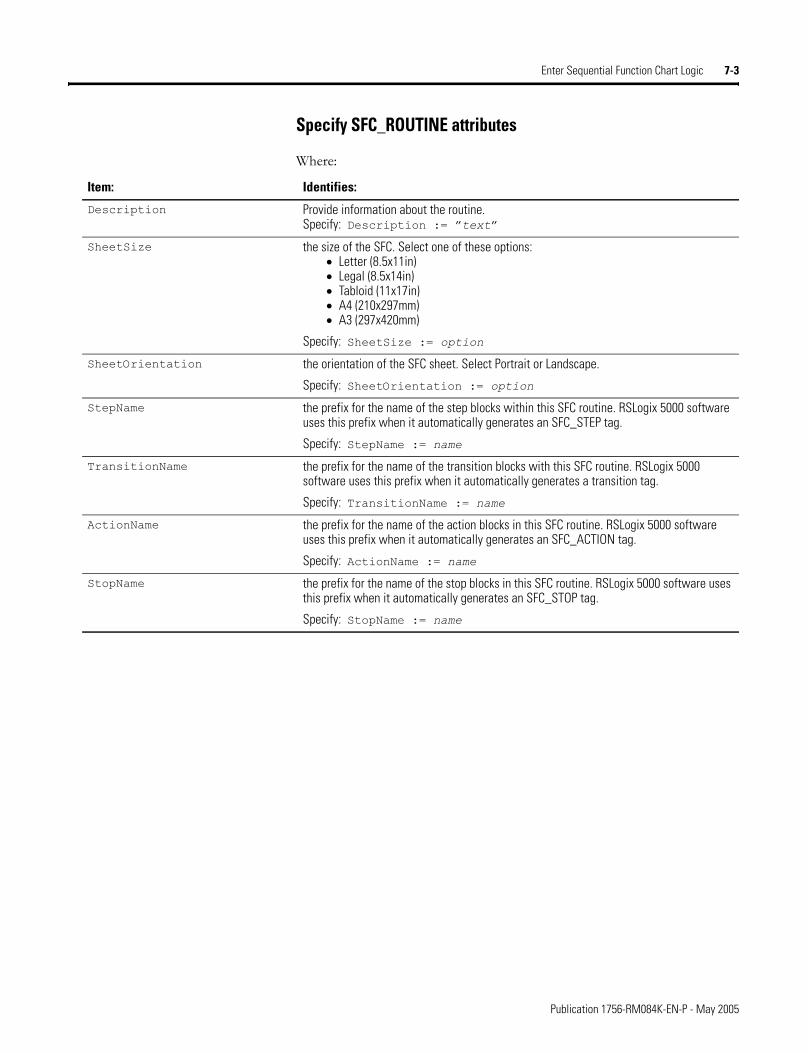
Enter Sequential Function Chart Logic 7-3
Specify SFC_ROUTINE attributes
Where:
Item: Identifies:
Description Provide information about the routine.Specify: Description := �text�
SheetSize the size of the SFC. Select one of these options:• Letter (8.5x11in)• Legal (8.5x14in)• Tabloid (11x17in)• A4 (210x297mm)• A3 (297x420mm)
Specify: SheetSize := option
SheetOrientation the orientation of the SFC sheet. Select Portrait or Landscape.
Specify: SheetOrientation := option
StepName the prefix for the name of the step blocks within this SFC routine. RSLogix 5000 software uses this prefix when it automatically generates an SFC_STEP tag.
Specify: StepName := name
TransitionName the prefix for the name of the transition blocks with this SFC routine. RSLogix 5000 software uses this prefix when it automatically generates a transition tag.
Specify: TransitionName := name
ActionName the prefix for the name of the action blocks in this SFC routine. RSLogix 5000 software uses this prefix when it automatically generates an SFC_ACTION tag.
Specify: ActionName := name
StopName the prefix for the name of the stop blocks in this SFC routine. RSLogix 5000 software uses this prefix when it automatically generates an SFC_STOP tag.
Specify: StopName := name
Publication 1756-RM084K-EN-P - May 2005
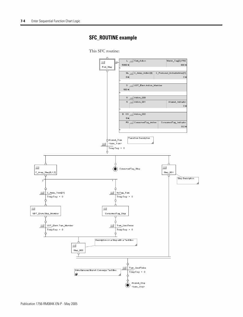
7-4 Enter Sequential Function Chart Logic
SFC_ROUTINE example
This SFC routine:
Publication 1756-RM084K-EN-P - May 2005
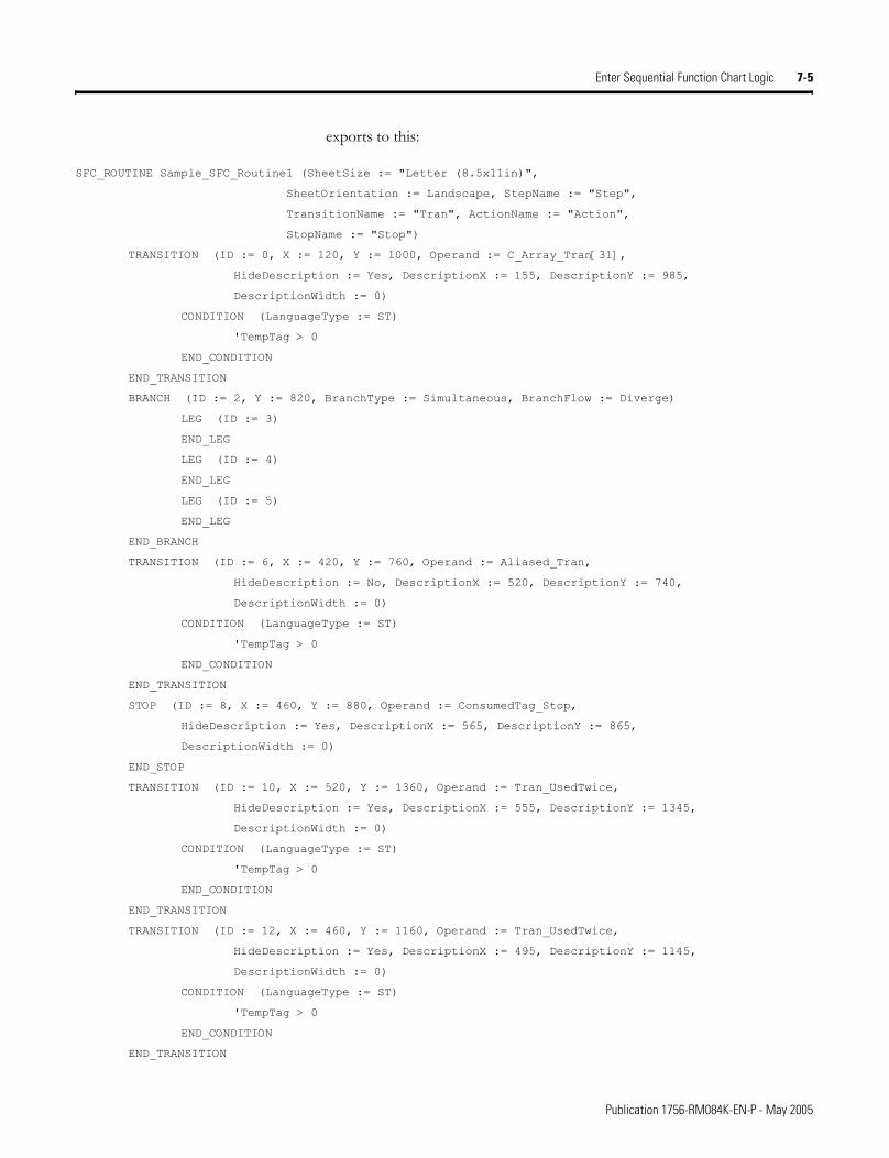
Enter Sequential Function Chart Logic 7-5
exports to this:
SFC_ROUTINE Sample_SFC_Routine1 (SheetSize := "Letter (8.5x11in)",
SheetOrientation := Landscape, StepName := "Step",
TransitionName := "Tran", ActionName := "Action",
StopName := "Stop")
TRANSITION (ID := 0, X := 120, Y := 1000, Operand := C_Array_Tran[31],
HideDescription := Yes, DescriptionX := 155, DescriptionY := 985,
DescriptionWidth := 0)
CONDITION (LanguageType := ST)
'TempTag > 0
END_CONDITION
END_TRANSITION
BRANCH (ID := 2, Y := 820, BranchType := Simultaneous, BranchFlow := Diverge)
LEG (ID := 3)
END_LEG
LEG (ID := 4)
END_LEG
LEG (ID := 5)
END_LEG
END_BRANCH
TRANSITION (ID := 6, X := 420, Y := 760, Operand := Aliased_Tran,
HideDescription := No, DescriptionX := 520, DescriptionY := 740,
DescriptionWidth := 0)
CONDITION (LanguageType := ST)
'TempTag > 0
END_CONDITION
END_TRANSITION
STOP (ID := 8, X := 460, Y := 880, Operand := ConsumedTag_Stop,
HideDescription := Yes, DescriptionX := 565, DescriptionY := 865,
DescriptionWidth := 0)
END_STOP
TRANSITION (ID := 10, X := 520, Y := 1360, Operand := Tran_UsedTwice,
HideDescription := Yes, DescriptionX := 555, DescriptionY := 1345,
DescriptionWidth := 0)
CONDITION (LanguageType := ST)
'TempTag > 0
END_CONDITION
END_TRANSITION
TRANSITION (ID := 12, X := 460, Y := 1160, Operand := Tran_UsedTwice,
HideDescription := Yes, DescriptionX := 495, DescriptionY := 1145,
DescriptionWidth := 0)
CONDITION (LanguageType := ST)
'TempTag > 0
END_CONDITION
END_TRANSITION
Publication 1756-RM084K-EN-P - May 2005
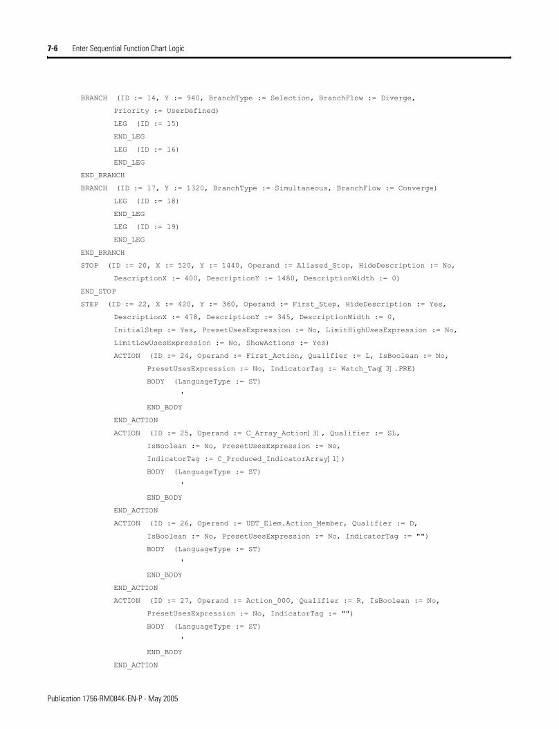
7-6 Enter Sequential Function Chart Logic
BRANCH (ID := 14, Y := 940, BranchType := Selection, BranchFlow := Diverge,
Priority := UserDefined)
LEG (ID := 15)
END_LEG
LEG (ID := 16)
END_LEG
END_BRANCH
BRANCH (ID := 17, Y := 1320, BranchType := Simultaneous, BranchFlow := Converge)
LEG (ID := 18)
END_LEG
LEG (ID := 19)
END_LEG
END_BRANCH
STOP (ID := 20, X := 520, Y := 1440, Operand := Aliased_Stop, HideDescription := No,
DescriptionX := 400, DescriptionY := 1480, DescriptionWidth := 0)
END_STOP
STEP (ID := 22, X := 420, Y := 360, Operand := First_Step, HideDescription := Yes,
DescriptionX := 478, DescriptionY := 345, DescriptionWidth := 0,
InitialStep := Yes, PresetUsesExpression := No, LimitHighUsesExpression := No,
LimitLowUsesExpression := No, ShowActions := Yes)
ACTION (ID := 24, Operand := First_Action, Qualifier := L, IsBoolean := No,
PresetUsesExpression := No, IndicatorTag := Watch_Tag[3].PRE)
BODY (LanguageType := ST)
'
END_BODY
END_ACTION
ACTION (ID := 25, Operand := C_Array_Action[3], Qualifier := SL,
IsBoolean := No, PresetUsesExpression := No,
IndicatorTag := C_Produced_IndicatorArray[1])
BODY (LanguageType := ST)
'
END_BODY
END_ACTION
ACTION (ID := 26, Operand := UDT_Elem.Action_Member, Qualifier := D,
IsBoolean := No, PresetUsesExpression := No, IndicatorTag := "")
BODY (LanguageType := ST)
'
END_BODY
END_ACTION
ACTION (ID := 27, Operand := Action_000, Qualifier := R, IsBoolean := No,
PresetUsesExpression := No, IndicatorTag := "")
BODY (LanguageType := ST)
'
END_BODY
END_ACTION
Publication 1756-RM084K-EN-P - May 2005
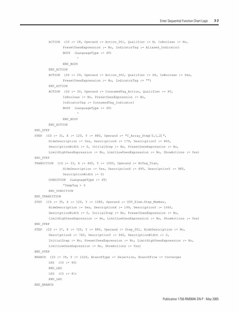
Enter Sequential Function Chart Logic 7-7
ACTION (ID := 28, Operand := Action_001, Qualifier := N, IsBoolean := No,
PresetUsesExpression := No, IndicatorTag := Aliased_Indicator)
BODY (LanguageType := ST)
'
END_BODY
END_ACTION
ACTION (ID := 29, Operand := Action_002, Qualifier := DS, IsBoolean := Yes,
PresetUsesExpression := No, IndicatorTag := "")
END_ACTION
ACTION (ID := 30, Operand := ConsumedTag_Action, Qualifier := P0,
IsBoolean := No, PresetUsesExpression := No,
IndicatorTag := ConsumedTag_Indicator)
BODY (LanguageType := ST)
'
END_BODY
END_ACTION
END_STEP
STEP (ID := 31, X := 120, Y := 880, Operand := "C_Array_Step[0,1,2]",
HideDescription := Yes, DescriptionX := 179, DescriptionY := 865,
DescriptionWidth := 0, InitialStep := No, PresetUsesExpression := No,
LimitHighUsesExpression := No, LimitLowUsesExpression := No, ShowActions := Yes)
END_STEP
TRANSITION (ID := 33, X := 460, Y := 1000, Operand := NoTag_Tran,
HideDescription := Yes, DescriptionX := 495, DescriptionY := 985,
DescriptionWidth := 0)
CONDITION (LanguageType := ST)
'TempTag > 0
END_CONDITION
END_TRANSITION
STEP (ID := 35, X := 120, Y := 1080, Operand := UDT_Elem.Step_Member,
HideDescription := Yes, DescriptionX := 199, DescriptionY := 1065,
DescriptionWidth := 0, InitialStep := No, PresetUsesExpression := No,
LimitHighUsesExpression := No, LimitLowUsesExpression := No, ShowActions := Yes)
END_STEP
STEP (ID := 37, X := 720, Y := 880, Operand := Step_001, HideDescription := No,
DescriptionX := 760, DescriptionY := 940, DescriptionWidth := 0,
InitialStep := No, PresetUsesExpression := No, LimitHighUsesExpression := No,
LimitLowUsesExpression := No, ShowActions := Yes)
END_STEP
BRANCH (ID := 39, Y := 1220, BranchType := Selection, BranchFlow := Converge)
LEG (ID := 40)
END_LEG
LEG (ID := 41)
END_LEG
END_BRANCH
Publication 1756-RM084K-EN-P - May 2005
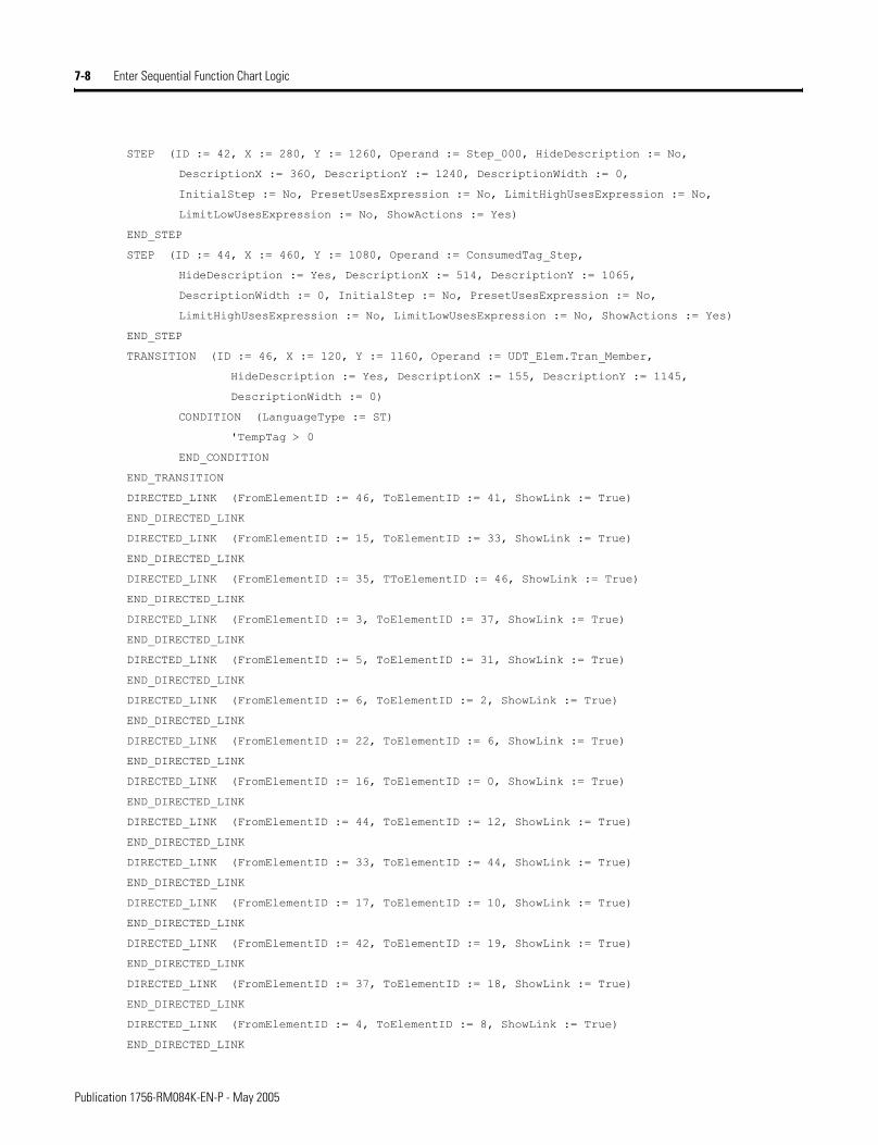
7-8 Enter Sequential Function Chart Logic
STEP (ID := 42, X := 280, Y := 1260, Operand := Step_000, HideDescription := No,
DescriptionX := 360, DescriptionY := 1240, DescriptionWidth := 0,
InitialStep := No, PresetUsesExpression := No, LimitHighUsesExpression := No,
LimitLowUsesExpression := No, ShowActions := Yes)
END_STEP
STEP (ID := 44, X := 460, Y := 1080, Operand := ConsumedTag_Step,
HideDescription := Yes, DescriptionX := 514, DescriptionY := 1065,
DescriptionWidth := 0, InitialStep := No, PresetUsesExpression := No,
LimitHighUsesExpression := No, LimitLowUsesExpression := No, ShowActions := Yes)
END_STEP
TRANSITION (ID := 46, X := 120, Y := 1160, Operand := UDT_Elem.Tran_Member,
HideDescription := Yes, DescriptionX := 155, DescriptionY := 1145,
DescriptionWidth := 0)
CONDITION (LanguageType := ST)
'TempTag > 0
END_CONDITION
END_TRANSITION
DIRECTED_LINK (FromElementID := 46, ToElementID := 41, ShowLink := True)
END_DIRECTED_LINK
DIRECTED_LINK (FromElementID := 15, ToElementID := 33, ShowLink := True)
END_DIRECTED_LINK
DIRECTED_LINK (FromElementID := 35, TToElementID := 46, ShowLink := True)
END_DIRECTED_LINK
DIRECTED_LINK (FromElementID := 3, ToElementID := 37, ShowLink := True)
END_DIRECTED_LINK
DIRECTED_LINK (FromElementID := 5, ToElementID := 31, ShowLink := True)
END_DIRECTED_LINK
DIRECTED_LINK (FromElementID := 6, ToElementID := 2, ShowLink := True)
END_DIRECTED_LINK
DIRECTED_LINK (FromElementID := 22, ToElementID := 6, ShowLink := True)
END_DIRECTED_LINK
DIRECTED_LINK (FromElementID := 16, ToElementID := 0, ShowLink := True)
END_DIRECTED_LINK
DIRECTED_LINK (FromElementID := 44, ToElementID := 12, ShowLink := True)
END_DIRECTED_LINK
DIRECTED_LINK (FromElementID := 33, ToElementID := 44, ShowLink := True)
END_DIRECTED_LINK
DIRECTED_LINK (FromElementID := 17, ToElementID := 10, ShowLink := True)
END_DIRECTED_LINK
DIRECTED_LINK (FromElementID := 42, ToElementID := 19, ShowLink := True)
END_DIRECTED_LINK
DIRECTED_LINK (FromElementID := 37, ToElementID := 18, ShowLink := True)
END_DIRECTED_LINK
DIRECTED_LINK (FromElementID := 4, ToElementID := 8, ShowLink := True)
END_DIRECTED_LINK
Publication 1756-RM084K-EN-P - May 2005
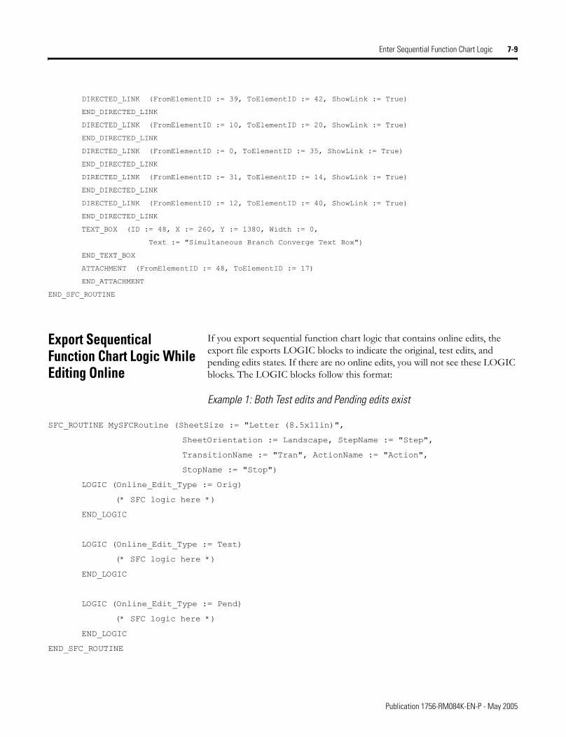
Enter Sequential Function Chart Logic 7-9
DIRECTED_LINK (FromElementID := 39, ToElementID := 42, ShowLink := True)
END_DIRECTED_LINK
DIRECTED_LINK (FromElementID := 10, ToElementID := 20, ShowLink := True)
END_DIRECTED_LINK
DIRECTED_LINK (FromElementID := 0, ToElementID := 35, ShowLink := True)
END_DIRECTED_LINK
DIRECTED_LINK (FromElementID := 31, ToElementID := 14, ShowLink := True)
END_DIRECTED_LINK
DIRECTED_LINK (FromElementID := 12, ToElementID := 40, ShowLink := True)
END_DIRECTED_LINK
TEXT_BOX (ID := 48, X := 260, Y := 1380, Width := 0,
Text := "Simultaneous Branch Converge Text Box")
END_TEXT_BOX
ATTACHMENT (FromElementID := 48, ToElementID := 17)
END_ATTACHMENT
END_SFC_ROUTINE
Export Sequentical Function Chart Logic While Editing Online
If you export sequential function chart logic that contains online edits, the export file exports LOGIC blocks to indicate the original, test edits, and pending edits states. If there are no online edits, you will not see these LOGIC blocks. The LOGIC blocks follow this format:
Example 1: Both Test edits and Pending edits exist
SFC_ROUTINE MySFCRoutine (SheetSize := "Letter (8.5x11in)",
SheetOrientation := Landscape, StepName := "Step",
TransitionName := "Tran", ActionName := "Action",
StopName := "Stop")
LOGIC (Online_Edit_Type := Orig)
(* SFC logic here *)
END_LOGIC
LOGIC (Online_Edit_Type := Test)
(* SFC logic here *)
END_LOGIC
LOGIC (Online_Edit_Type := Pend)
(* SFC logic here *)
END_LOGIC
END_SFC_ROUTINE
Publication 1756-RM084K-EN-P - May 2005
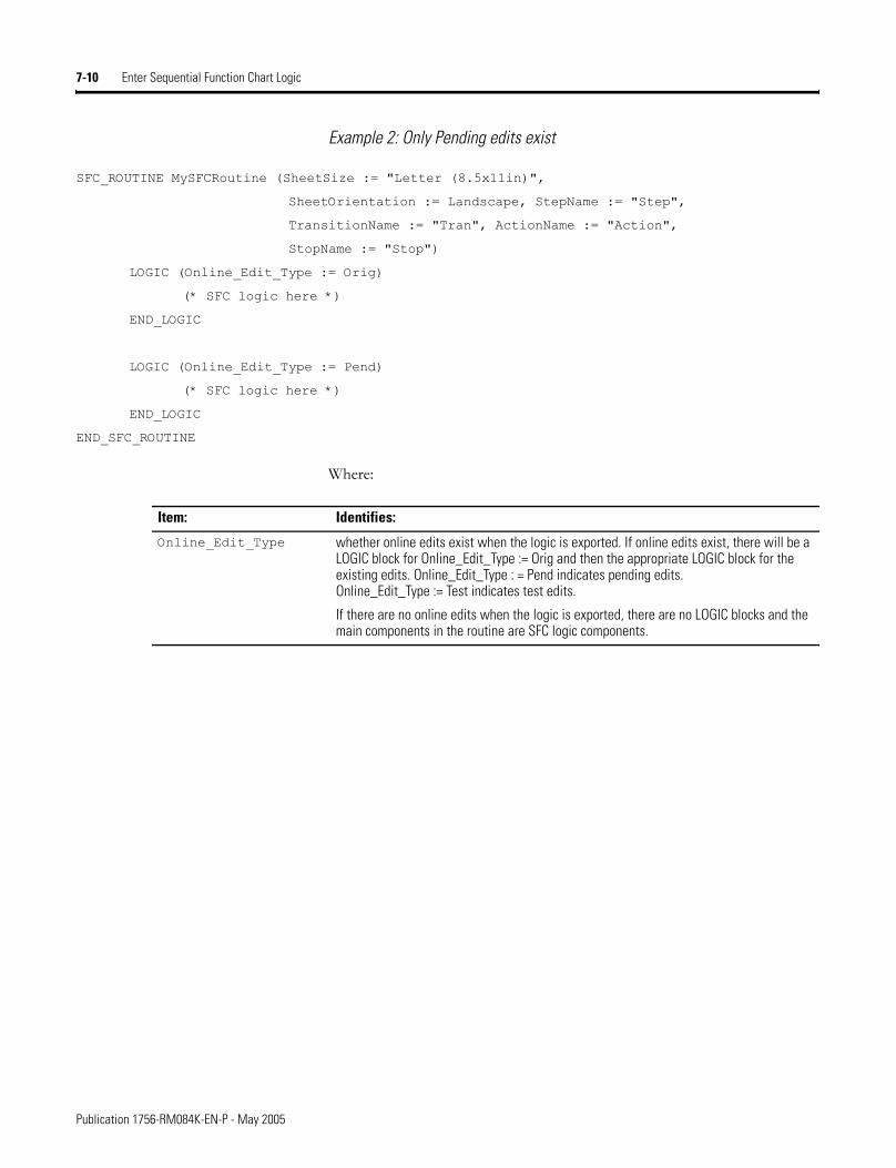
7-10 Enter Sequential Function Chart Logic
Example 2: Only Pending edits exist
SFC_ROUTINE MySFCRoutine (SheetSize := "Letter (8.5x11in)",
SheetOrientation := Landscape, StepName := "Step",
TransitionName := "Tran", ActionName := "Action",
StopName := "Stop")
LOGIC (Online_Edit_Type := Orig)
(* SFC logic here *)
END_LOGIC
LOGIC (Online_Edit_Type := Pend)
(* SFC logic here *)
END_LOGIC
END_SFC_ROUTINE
Where:
Item: Identifies:
Online_Edit_Type whether online edits exist when the logic is exported. If online edits exist, there will be a LOGIC block for Online_Edit_Type := Orig and then the appropriate LOGIC block for the existing edits. Online_Edit_Type : = Pend indicates pending edits. Online_Edit_Type := Test indicates test edits.
If there are no online edits when the logic is exported, there are no LOGIC blocks and the main components in the routine are SFC logic components.
Publication 1756-RM084K-EN-P - May 2005
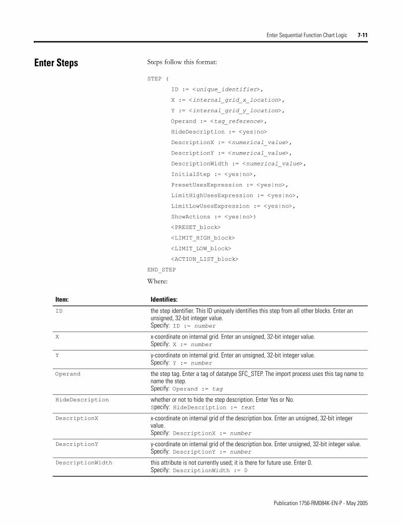
Enter Sequential Function Chart Logic 7-11
Enter Steps Steps follow this format:
STEP (
ID := <unique_identifier>,
X := <internal_grid_x_location>,
Y := <internal_grid_y_location>,
Operand := <tag_reference>,
HideDescription := <yes|no>
DescriptionX := <numerical_value>,
DescriptionY := <numerical_value>,
DescriptionWidth := <numerical_value>,
InitialStep := <yes|no>,
PresetUsesExpression := <yes|no>,
LimitHighUsesExpression := <yes|no>,
LimitLowUsesExpression := <yes|no>,
ShowActions := <yes|no>)
<PRESET_block>
<LIMIT_HIGH_block>
<LIMIT_LOW_block>
<ACTION_LIST_block>
END_STEP
Where:
Item: Identifies:
ID the step identifier. This ID uniquely identifies this step from all other blocks. Enter an unsigned, 32-bit integer value. Specify: ID := number
X x-coordinate on internal grid. Enter an unsigned, 32-bit integer value.Specify: X := number
Y y-coordinate on internal grid. Enter an unsigned, 32-bit integer value.Specify: Y := number
Operand the step tag. Enter a tag of datatype SFC_STEP. The import process uses this tag name to name the step.Specify: Operand := tag
HideDescription whether or not to hide the step description. Enter Yes or No.Specify: HideDescription := text
DescriptionX x-coordinate on internal grid of the description box. Enter an unsigned, 32-bit integer value.Specify: DescriptionX := number
DescriptionY y-coordinate on internal grid of the description box. Enter unsigned, 32-bit integer value.Specify: DescriptionY := number
DescriptionWidth this attribute is not currently used; it is there for future use. Enter 0.Specify: DescriptionWidth := 0
Publication 1756-RM084K-EN-P - May 2005
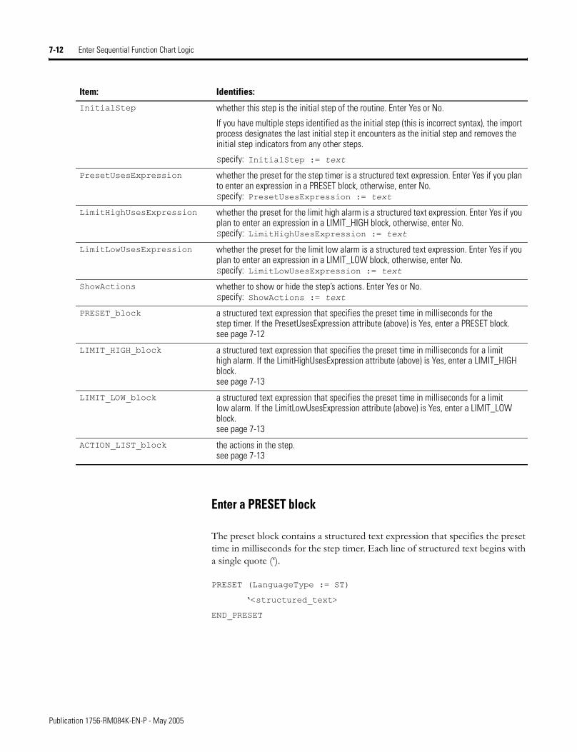
7-12 Enter Sequential Function Chart Logic
Enter a PRESET block
The preset block contains a structured text expression that specifies the preset time in milliseconds for the step timer. Each line of structured text begins with a single quote (�).
PRESET (LanguageType := ST)
�<structured_text>
END_PRESET
InitialStep whether this step is the initial step of the routine. Enter Yes or No.
If you have multiple steps identified as the initial step (this is incorrect syntax), the import process designates the last initial step it encounters as the initial step and removes the initial step indicators from any other steps.
Specify: InitialStep := text
PresetUsesExpression whether the preset for the step timer is a structured text expression. Enter Yes if you plan to enter an expression in a PRESET block, otherwise, enter No.Specify: PresetUsesExpression := text
LimitHighUsesExpression whether the preset for the limit high alarm is a structured text expression. Enter Yes if you plan to enter an expression in a LIMIT_HIGH block, otherwise, enter No.Specify: LimitHighUsesExpression := text
LimitLowUsesExpression whether the preset for the limit low alarm is a structured text expression. Enter Yes if you plan to enter an expression in a LIMIT_LOW block, otherwise, enter No.Specify: LimitLowUsesExpression := text
ShowActions whether to show or hide the step’s actions. Enter Yes or No.Specify: ShowActions := text
PRESET_block a structured text expression that specifies the preset time in milliseconds for the step timer. If the PresetUsesExpression attribute (above) is Yes, enter a PRESET block.see page 7-12
LIMIT_HIGH_block a structured text expression that specifies the preset time in milliseconds for a limit high alarm. If the LimitHighUsesExpression attribute (above) is Yes, enter a LIMIT_HIGH block.see page 7-13
LIMIT_LOW_block a structured text expression that specifies the preset time in milliseconds for a limit low alarm. If the LimitLowUsesExpression attribute (above) is Yes, enter a LIMIT_LOW block.see page 7-13
ACTION_LIST_block the actions in the step.see page 7-13
Item: Identifies:
Publication 1756-RM084K-EN-P - May 2005
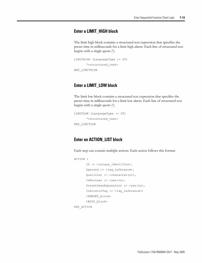
Enter Sequential Function Chart Logic 7-13
Enter a LIMIT_HIGH block
The limit high block contains a structured text expression that specifies the preset time in milliseconds for a limit high alarm. Each line of structured text begins with a single quote (�).
LIMITHIGH (LanguageType := ST)
�<structured_text>
END_LIMITHIGH
Enter a LIMIT_LOW block
The limit low block contains a structured text expression that specifies the preset time in milliseconds for a limit low alarm. Each line of structured text begins with a single quote (�).
LIMITLOW (LanguageType := ST)
�<structured_text>
END_LIMITLOW
Enter an ACTION_LIST block
Each step can contain multiple actions. Each action follows this format:
ACTION (
ID := <unique_identifier>,
Operand := <tag_reference>,
Qualifier := <character(s)>,
IsBoolean := <yes|no>,
PresetUsesExpression := <yes|no>,
IndicatorTag := <tag_reference>)
<PRESET_block>
<BODY_block>
END_ACTION
Publication 1756-RM084K-EN-P - May 2005
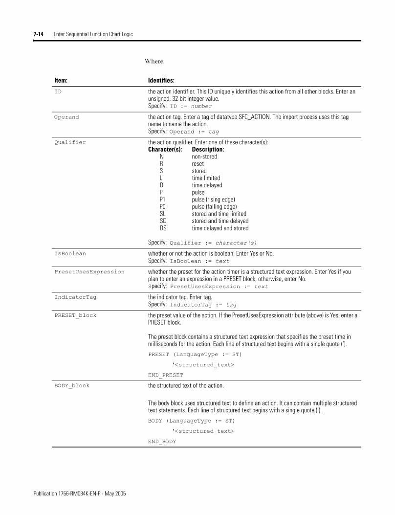
7-14 Enter Sequential Function Chart Logic
Where:
Item: Identifies:
ID the action identifier. This ID uniquely identifies this action from all other blocks. Enter an unsigned, 32-bit integer value.Specify: ID := number
Operand the action tag. Enter a tag of datatype SFC_ACTION. The import process uses this tag name to name the action.Specify: Operand := tag
Qualifier the action qualifier. Enter one of these character(s):Character(s): Description:
N non-storedR resetS storedL time limitedD time delayedP pulseP1 pulse (rising edge)P0 pulse (falling edge)SL stored and time limitedSD stored and time delayedDS time delayed and stored
Specify: Qualifier := character(s)
IsBoolean whether or not the action is boolean. Enter Yes or No.Specify: IsBoolean := text
PresetUsesExpression whether the preset for the action timer is a structured text expression. Enter Yes if you plan to enter an expression in a PRESET block, otherwise, enter No.Specify: PresetUsesExpression := text
IndicatorTag the indicator tag. Enter tag.Specify: IndicatorTag := tag
PRESET_block the preset value of the action. If the PresetUsesExpression attribute (above) is Yes, enter a PRESET block.
The preset block contains a structured text expression that specifies the preset time in milliseconds for the action. Each line of structured text begins with a single quote (‘).
PRESET (LanguageType := ST)
�<structured_text>
END_PRESET
BODY_block the structured text of the action.
The body block uses structured text to define an action. It can contain multiple structured text statements. Each line of structured text begins with a single quote (‘).
BODY (LanguageType := ST)
�<structured_text>
END_BODY
Publication 1756-RM084K-EN-P - May 2005
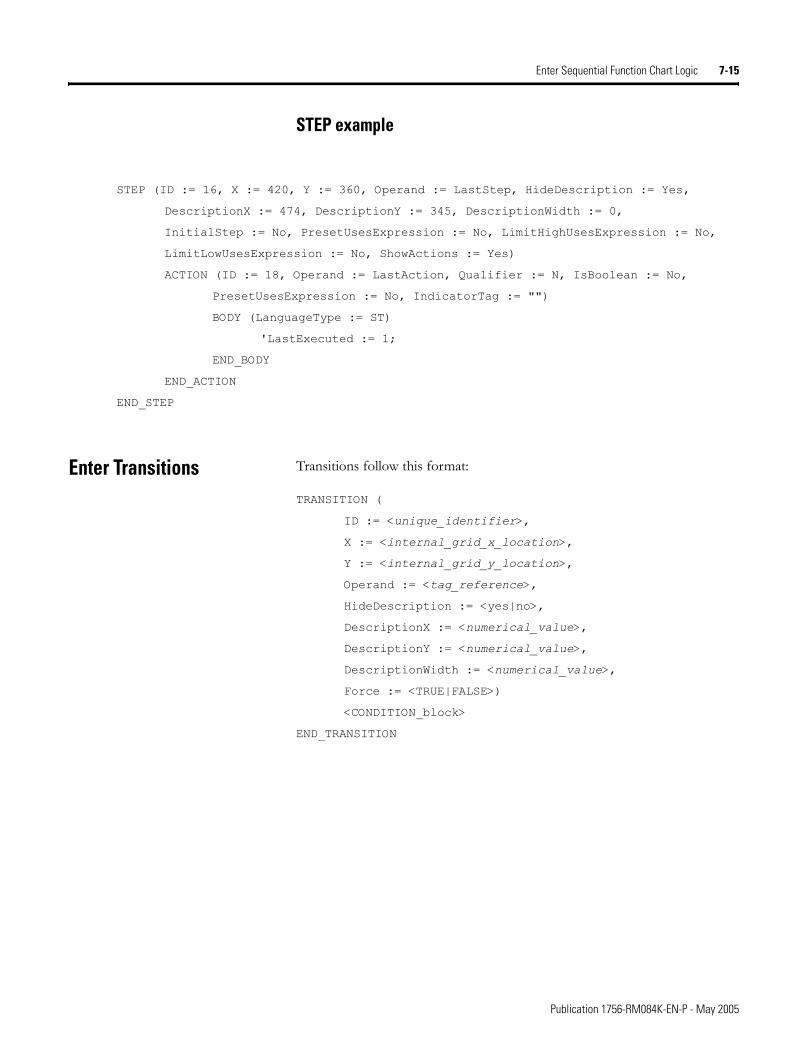
Enter Sequential Function Chart Logic 7-15
STEP example
STEP (ID := 16, X := 420, Y := 360, Operand := LastStep, HideDescription := Yes,
DescriptionX := 474, DescriptionY := 345, DescriptionWidth := 0,
InitialStep := No, PresetUsesExpression := No, LimitHighUsesExpression := No,
LimitLowUsesExpression := No, ShowActions := Yes)
ACTION (ID := 18, Operand := LastAction, Qualifier := N, IsBoolean := No,
PresetUsesExpression := No, IndicatorTag := "")
BODY (LanguageType := ST)
'LastExecuted := 1;
END_BODY
END_ACTION
END_STEP
Enter Transitions Transitions follow this format:
TRANSITION (
ID := <unique_identifier>,
X := <internal_grid_x_location>,
Y := <internal_grid_y_location>,
Operand := <tag_reference>,
HideDescription := <yes|no>,
DescriptionX := <numerical_value>,
DescriptionY := <numerical_value>,
DescriptionWidth := <numerical_value>,
Force := <TRUE|FALSE>)
<CONDITION_block>
END_TRANSITION
Publication 1756-RM084K-EN-P - May 2005
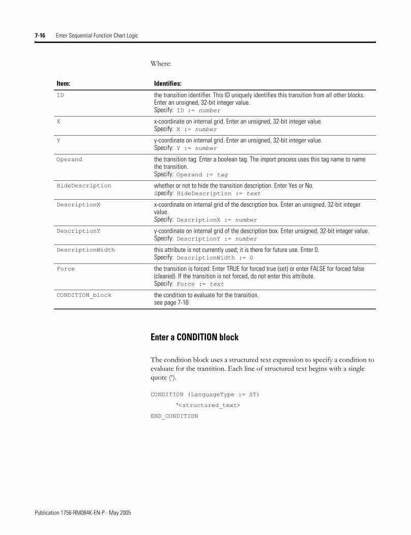
7-16 Enter Sequential Function Chart Logic
Where:
Enter a CONDITION block
The condition block uses a structured text expression to specify a condition to evaluate for the transition. Each line of structured text begins with a single quote (�).
CONDITION (LanguageType := ST)
�<structured_text>
END_CONDITION
Item: Identifies:
ID the transition identifier. This ID uniquely identifies this transition from all other blocks. Enter an unsigned, 32-bit integer value.Specify: ID := number
X x-coordinate on internal grid. Enter an unsigned, 32-bit integer value.Specify: X := number
Y y-coordinate on internal grid. Enter an unsigned, 32-bit integer value.Specify: Y := number
Operand the transition tag. Enter a boolean tag. The import process uses this tag name to name the transition.Specify: Operand := tag
HideDescription whether or not to hide the transition description. Enter Yes or No.Specify: HideDescription := text
DescriptionX x-coordinate on internal grid of the description box. Enter an unsigned, 32-bit integer value.Specify: DescriptionX := number
DescriptionY y-coordinate on internal grid of the description box. Enter unsigned, 32-bit integer value.Specify: DescriptionY := number
DescriptionWidth this attribute is not currently used; it is there for future use. Enter 0.Specify: DescriptionWidth := 0
Force the transition is forced. Enter TRUE for forced true (set) or enter FALSE for forced false (cleared). If the transition is not forced, do not enter this attribute.Specify: Force := text
CONDITION_block the condition to evaluate for the transition.see page 7-16
Publication 1756-RM084K-EN-P - May 2005
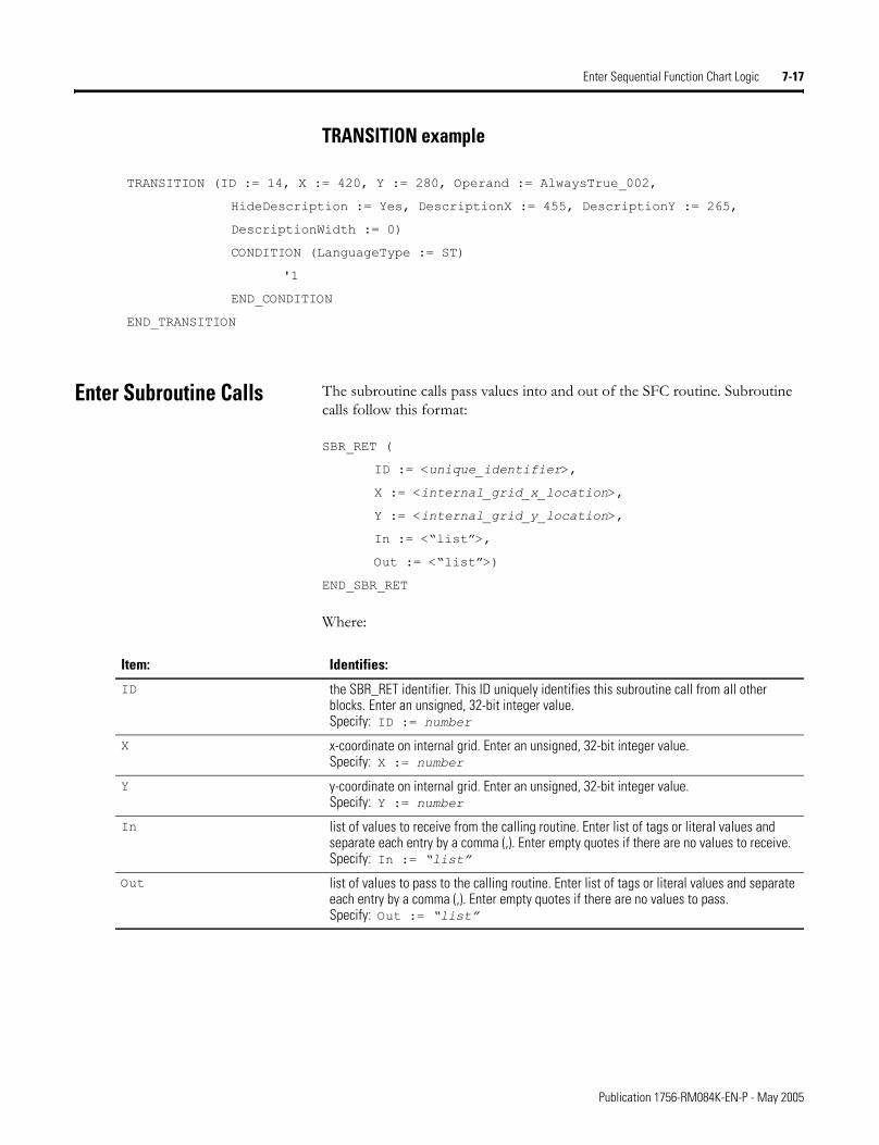
Enter Sequential Function Chart Logic 7-17
TRANSITION example
TRANSITION (ID := 14, X := 420, Y := 280, Operand := AlwaysTrue_002,
HideDescription := Yes, DescriptionX := 455, DescriptionY := 265,
DescriptionWidth := 0)
CONDITION (LanguageType := ST)
'1
END_CONDITION
END_TRANSITION
Enter Subroutine Calls The subroutine calls pass values into and out of the SFC routine. Subroutine calls follow this format:
SBR_RET (
ID := <unique_identifier>,
X := <internal_grid_x_location>,
Y := <internal_grid_y_location>,
In := <�list�>,
Out := <�list�>)
END_SBR_RET
Where:
Item: Identifies:
ID the SBR_RET identifier. This ID uniquely identifies this subroutine call from all other blocks. Enter an unsigned, 32-bit integer value.Specify: ID := number
X x-coordinate on internal grid. Enter an unsigned, 32-bit integer value.Specify: X := number
Y y-coordinate on internal grid. Enter an unsigned, 32-bit integer value.Specify: Y := number
In list of values to receive from the calling routine. Enter list of tags or literal values and separate each entry by a comma (,). Enter empty quotes if there are no values to receive.Specify: In := �list�
Out list of values to pass to the calling routine. Enter list of tags or literal values and separate each entry by a comma (,). Enter empty quotes if there are no values to pass.Specify: Out := �list�
Publication 1756-RM084K-EN-P - May 2005
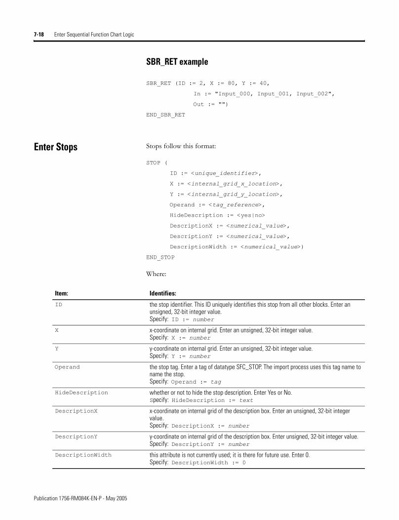
7-18 Enter Sequential Function Chart Logic
SBR_RET example
SBR_RET (ID := 2, X := 80, Y := 40,
In := "Input_000, Input_001, Input_002",
Out := "")
END_SBR_RET
Enter Stops Stops follow this format:
STOP (
ID := <unique_identifier>,
X := <internal_grid_x_location>,
Y := <internal_grid_y_location>,
Operand := <tag_reference>,
HideDescription := <yes|no>
DescriptionX := <numerical_value>,
DescriptionY := <numerical_value>,
DescriptionWidth := <numerical_value>)
END_STOP
Where:
Item: Identifies:
ID the stop identifier. This ID uniquely identifies this stop from all other blocks. Enter an unsigned, 32-bit integer value.Specify: ID := number
X x-coordinate on internal grid. Enter an unsigned, 32-bit integer value.Specify: X := number
Y y-coordinate on internal grid. Enter an unsigned, 32-bit integer value.Specify: Y := number
Operand the stop tag. Enter a tag of datatype SFC_STOP. The import process uses this tag name to name the stop.Specify: Operand := tag
HideDescription whether or not to hide the stop description. Enter Yes or No.Specify: HideDescription := text
DescriptionX x-coordinate on internal grid of the description box. Enter an unsigned, 32-bit integer value.Specify: DescriptionX := number
DescriptionY y-coordinate on internal grid of the description box. Enter unsigned, 32-bit integer value.Specify: DescriptionY := number
DescriptionWidth this attribute is not currently used; it is there for future use. Enter 0.Specify: DescriptionWidth := 0
Publication 1756-RM084K-EN-P - May 2005
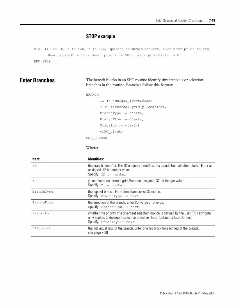
Enter Sequential Function Chart Logic 7-19
STOP example
STOP (ID := 10, X := 420, Y := 520, Operand := NeverGetsHere, HideDescription := Yes,
DescriptionX := 505, DescriptionY := 505, DescriptionWidth := 0)
END_STOP
Enter Branches The branch blocks in an SFC routine identify simultaneous or selection branches in the routine. Branches follow this format:
BRANCH (
ID := <unique_identifier>,
Y := <internal_grid_y_location>,
BranchType := <text>,
BranchFlow := <text>,
Priority := <text>)
<LEG_block>
END_BRANCH
Where:
Item: Identifies:
ID the branch identifier. This ID uniquely identifies this branch from all other blocks. Enter an unsigned, 32-bit integer value.Specify: ID := number
Y y-coordinate on internal grid. Enter an unsigned, 32-bit integer value.Specify: Y := number
BranchType the type of branch. Enter Simultaneous or Selection.Specify: BranchType := text
BranchFlow the direction of the branch. Enter Converge or Diverge.Specify: BranchFlow := text
Priority whether the priority of a divergent selection branch is defined by the user. This attribute only applies to divergent selection branches. Enter Default or UserDefined.Specify: Priority := text
LEG_block the individual legs of the branch. Enter one leg block for each leg of the branch.see page 7-20
Publication 1756-RM084K-EN-P - May 2005
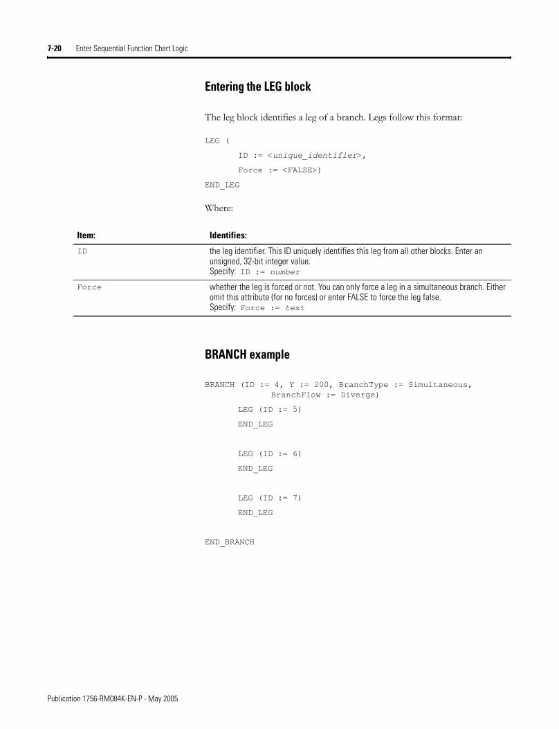
7-20 Enter Sequential Function Chart Logic
Entering the LEG block
The leg block identifies a leg of a branch. Legs follow this format:
LEG (
ID := <unique_identifier>,
Force := <FALSE>)
END_LEG
Where:
BRANCH example
BRANCH (ID := 4, Y := 200, BranchType := Simultaneous, BranchFlow := Diverge)
LEG (ID := 5)
END_LEG
LEG (ID := 6)
END_LEG
LEG (ID := 7)
END_LEG
END_BRANCH
Item: Identifies:
ID the leg identifier. This ID uniquely identifies this leg from all other blocks. Enter an unsigned, 32-bit integer value.Specify: ID := number
Force whether the leg is forced or not. You can only force a leg in a simultaneous branch. Either omit this attribute (for no forces) or enter FALSE to force the leg false.Specify: Force := text
Publication 1756-RM084K-EN-P - May 2005
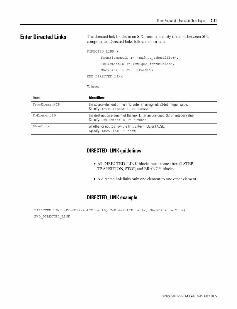
Enter Sequential Function Chart Logic 7-21
Enter Directed Links The directed link blocks in an SFC routine identify the links between SFC components. Directed links follow this format:
DIRECTED_LINK (
FromElementID := <unique_identifier>,
ToElementID := <unique_identifier>,
ShowLink := <TRUE|FALSE>)
END_DIRECTED_LINK
Where:
DIRECTED_LINK guidelines
• All DIRECTED_LINK blocks must come after all STEP, TRANSITION, STOP, and BRANCH blocks.
• A directed link links only one element to one other element.
DIRECTED_LINK example
DIRECTED_LINK (FromElementID := 16, ToElementID := 12, ShowLink := True)
END_DIRECTED_LINK
Item: Identifies:
FromElementID the source element of the link. Enter an unsigned, 32-bit integer value.Specify: FromElementID := number
ToElementID the destination element of the link. Enter an unsigned, 32-bit integer value.Specify: ToElementID := number
ShowLink whether or not to show the link. Enter TRUE or FALSE.Specify: ShowLink := text
Publication 1756-RM084K-EN-P - May 2005
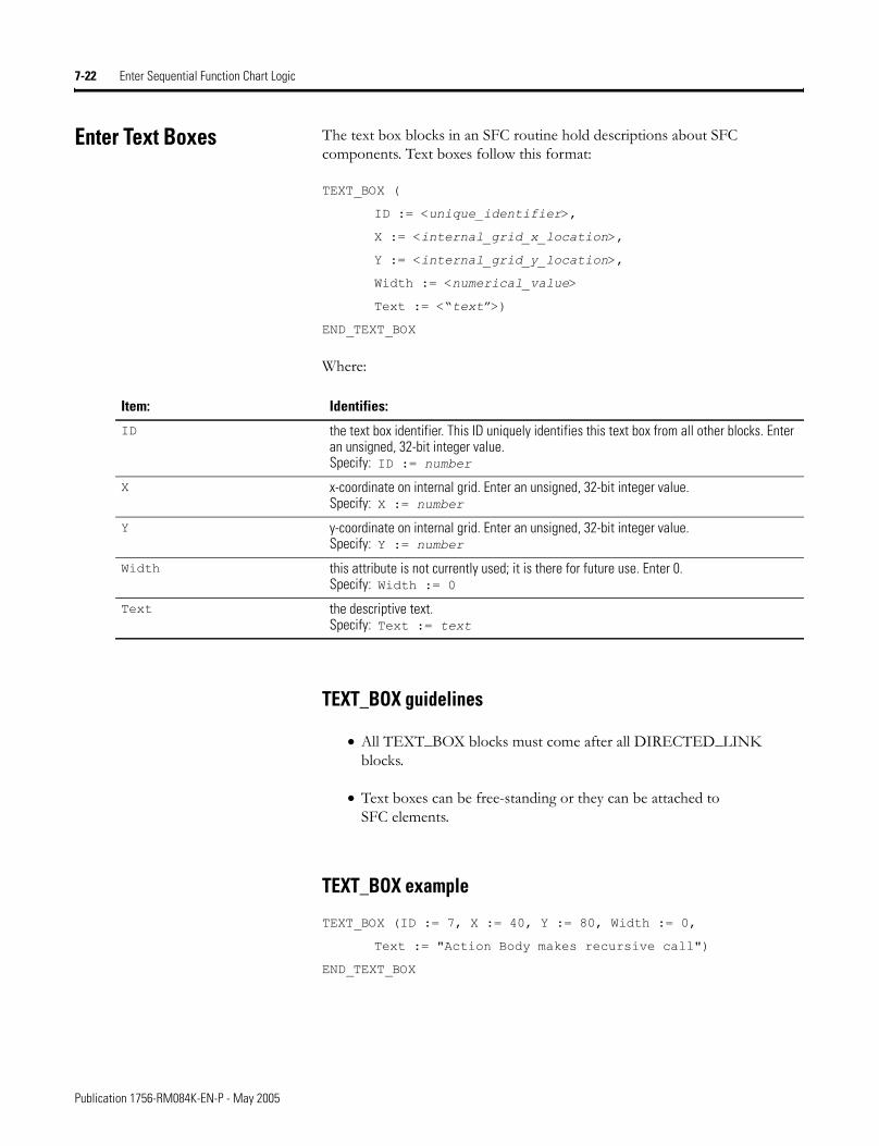
7-22 Enter Sequential Function Chart Logic
Enter Text Boxes The text box blocks in an SFC routine hold descriptions about SFC components. Text boxes follow this format:
TEXT_BOX (
ID := <unique_identifier>,
X := <internal_grid_x_location>,
Y := <internal_grid_y_location>,
Width := <numerical_value>
Text := <�text�>)
END_TEXT_BOX
Where:
TEXT_BOX guidelines
• All TEXT_BOX blocks must come after all DIRECTED_LINK blocks.
• Text boxes can be free-standing or they can be attached to SFC elements.
TEXT_BOX example
TEXT_BOX (ID := 7, X := 40, Y := 80, Width := 0,
Text := "Action Body makes recursive call")
END_TEXT_BOX
Item: Identifies:
ID the text box identifier. This ID uniquely identifies this text box from all other blocks. Enter an unsigned, 32-bit integer value.Specify: ID := number
X x-coordinate on internal grid. Enter an unsigned, 32-bit integer value.Specify: X := number
Y y-coordinate on internal grid. Enter an unsigned, 32-bit integer value.Specify: Y := number
Width this attribute is not currently used; it is there for future use. Enter 0.Specify: Width := 0
Text the descriptive text.Specify: Text := text
Publication 1756-RM084K-EN-P - May 2005
Enter Sequential Function Chart Logic 7-23
Enter Attachments The attachment blocks in an SFC routine identify the attachments from text boxes to other SFC elements. Attachments follow this format:
ATTACHMENT (
FromElementID := <unique_identifier>,
ToElementID := <unique_identifier>,
END_ATTACHMENT
Where:
ATTACHMENT guidelines
• Use an attachment to link a text box to an SFC element.
• All ATTACHMENT blocks must come after all TEXT_BOX blocks.
ATTACHMENT example
ATTACHMENT (FromElementID := 7, ToElementID := 2)
END_ATTACHMENT
Item: Identifies:
FromElementID the ID of the attached object. Enter an unsigned, 32-bit integer value.Specify: FromElementID := number
ToElementID the ID of the object that the FromID object is attached to. Enter an unsigned, 32-bit integer value.Specify: ToElementID := number
Publication 1756-RM084K-EN-P - May 2005

7-24 Enter Sequential Function Chart Logic
Notes:
Publication 1756-RM084K-EN-P - May 2005
Chapter 8
Structure the Tag/Comments (.CSV) Import/Export File Format
Introduction This chapter explains the overall structure of the .CSV file that can store exported tags and rung comments.
Place Information in a .CSV File
The CSV import/export file contains these components of information:
Internal file comments
You can enter comments to document import files. The import process ignores these comments. You can place comments anywhere in an import/export file, except in names and descriptions. Enter comments by starting the line (record) with REMARK and a comma.
For information about: See page:
Place information in a .CSV file 8-1
Specify a tag record 8-2
Specify a rung comment record 8-4
Example CSV files 8-5
Item: Identifies:
remark comment within the CSV file
TAG tag
RCOMMENT rung comment
1 Publication 1756-RM084K-EN-P - May 2005
8-2 Structure the Tag/Comments (.CSV) Import/Export File Format
Specify a Tag Record Each tag record defines a tag within a controller project. A TAG record includes this information:
TAG type record
Each TAG record defines a tag within a controller project. A TAG record follows this format:
TAG,�Scope�,�Name�,�Description�,�Datatype�,�Specifier�,�Attributes�
Specify tag dimensions on the Datatype as:
Item: Identifies:
Type the type of tagvalid types are:TAG tag ALIAS alias tagCOMMENT tag operand component
Scope what part of the project owns the tagif no scope is specified, the scope is controllerif a scope is specified, it identifies the program or equipment phase
Name name of the tag
Description description of the tag (optional)
Datatype datatype of the tag - use any valid datatype name
Specifier optional• for an alias, specifies base tag• for a tag comment, specifies the tag name and member or bit
Attributes the attributes of the tag, as exported in the .L5K formatdefine how the tag can be used and how it appearsattributes do not include tag values
To specify: Enter:
1 dimension [a]
2 dimensions [a,b]
3 dimensions [a,b,c]
Publication 1756-RM084K-EN-P - May 2005
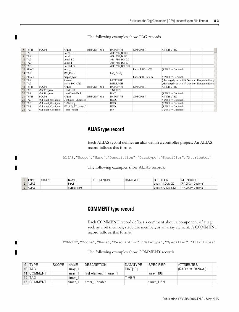
Structure the Tag/Comments (.CSV) Import/Export File Format 8-3
The following examples show TAG records.
ALIAS type record
Each ALIAS record defines an alias within a controller project. An ALIAS record follows this format:
ALIAS,�Scope�,�Name�,�Description�,�Datatype�,�Specifier�,�Attributes�
The following examples show ALIAS records.
COMMENT type record
Each COMMENT record defines a comment about a component of a tag, such as a bit member, structure member, or an array element. A COMMENT record follows this format:
COMMENT,�Scope�,�Name�,�Description�,�Datatype�,�Specifier�,�Attributes�
The following examples show COMMENT records.
Publication 1756-RM084K-EN-P - May 2005
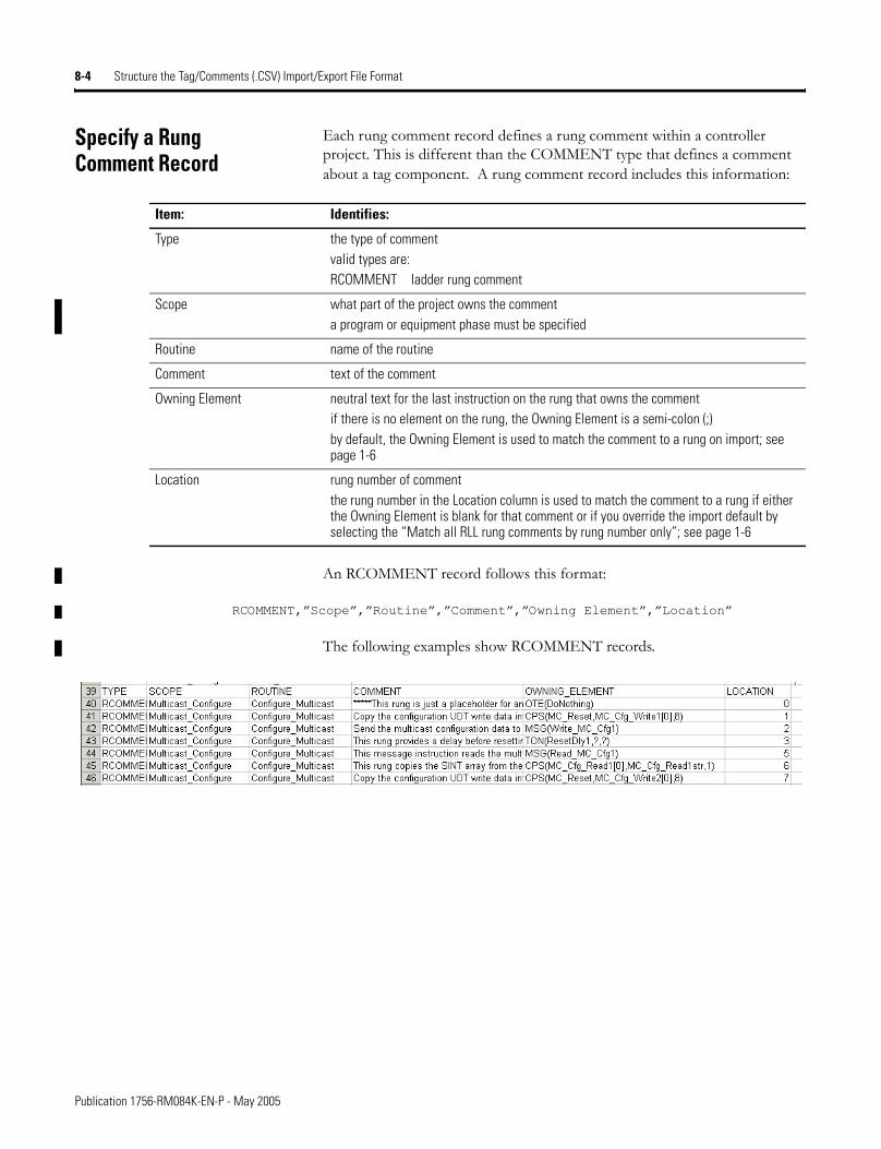
8-4 Structure the Tag/Comments (.CSV) Import/Export File Format
Specify a Rung Comment Record
Each rung comment record defines a rung comment within a controller project. This is different than the COMMENT type that defines a comment about a tag component. A rung comment record includes this information:
An RCOMMENT record follows this format:
RCOMMENT,�Scope�,�Routine�,�Comment�,�Owning Element�,�Location�
The following examples show RCOMMENT records.
Item: Identifies:
Type the type of commentvalid types are:RCOMMENT ladder rung comment
Scope what part of the project owns the commenta program or equipment phase must be specified
Routine name of the routine
Comment text of the comment
Owning Element neutral text for the last instruction on the rung that owns the commentif there is no element on the rung, the Owning Element is a semi-colon (;)by default, the Owning Element is used to match the comment to a rung on import; see page 1-6
Location rung number of commentthe rung number in the Location column is used to match the comment to a rung if either the Owning Element is blank for that comment or if you override the import default by selecting the “Match all RLL rung comments by rung number only”; see page 1-6
Publication 1756-RM084K-EN-P - May 2005
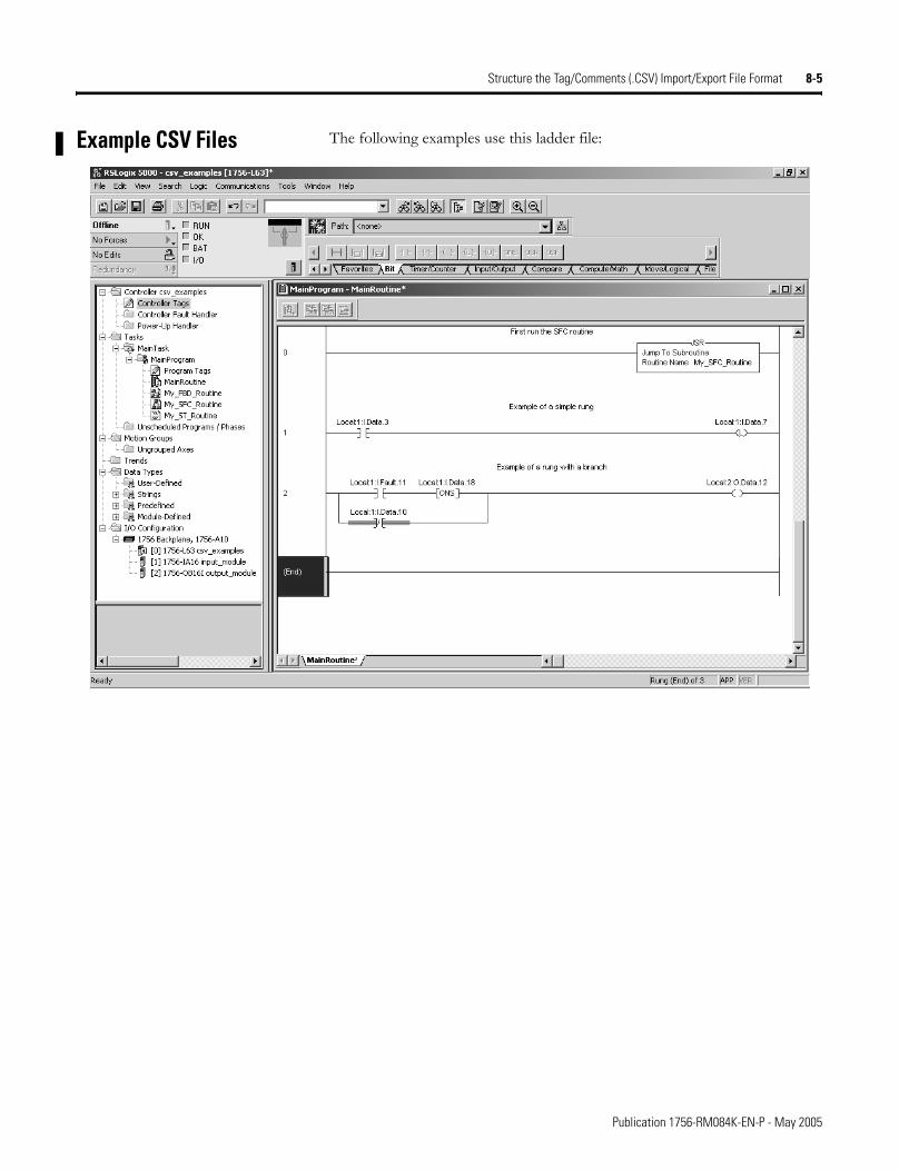
Structure the Tag/Comments (.CSV) Import/Export File Format 8-5
Example CSV Files The following examples use this ladder file:
Publication 1756-RM084K-EN-P - May 2005
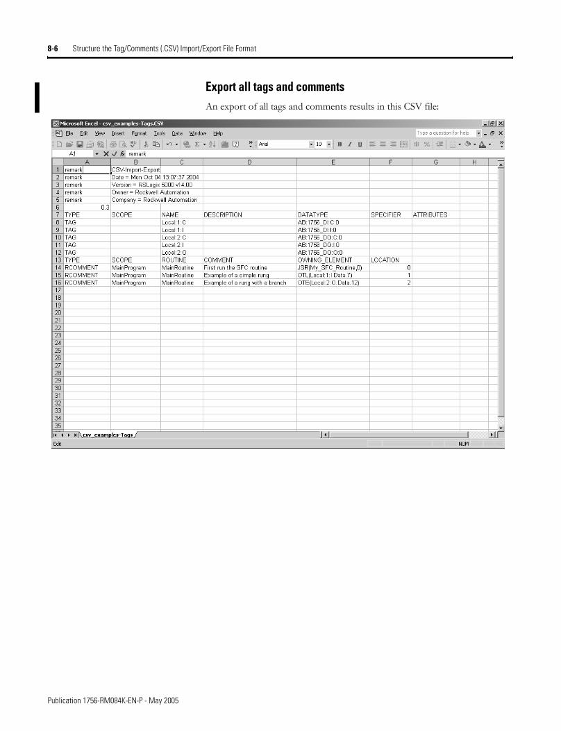
8-6 Structure the Tag/Comments (.CSV) Import/Export File Format
Export all tags and commentsAn export of all tags and comments results in this CSV file:
Publication 1756-RM084K-EN-P - May 2005
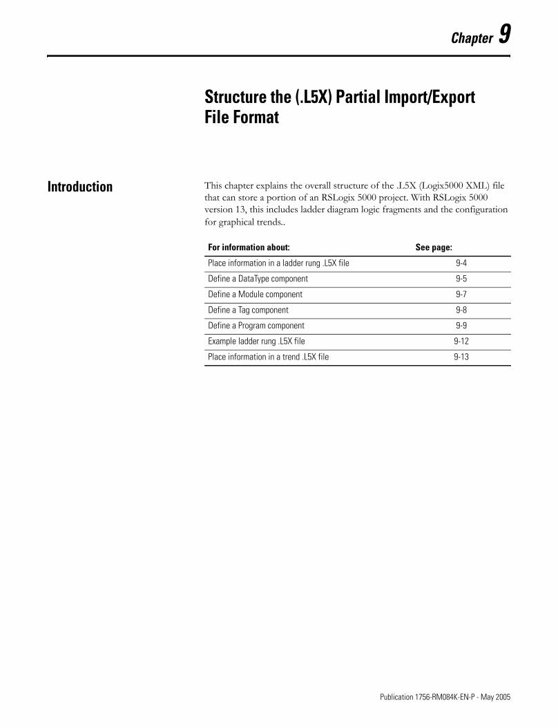
Chapter 9
Structure the (.L5X) Partial Import/Export File Format
Introduction This chapter explains the overall structure of the .L5X (Logix5000 XML) file that can store a portion of an RSLogix 5000 project. With RSLogix 5000 version 13, this includes ladder diagram logic fragments and the configuration for graphical trends..
For information about: See page:
Place information in a ladder rung .L5X file 9-4
Define a DataType component 9-5
Define a Module component 9-7
Define a Tag component 9-8
Define a Program component 9-9
Example ladder rung .L5X file 9-12
Place information in a trend .L5X file 9-13
1 Publication 1756-RM084K-EN-P - May 2005
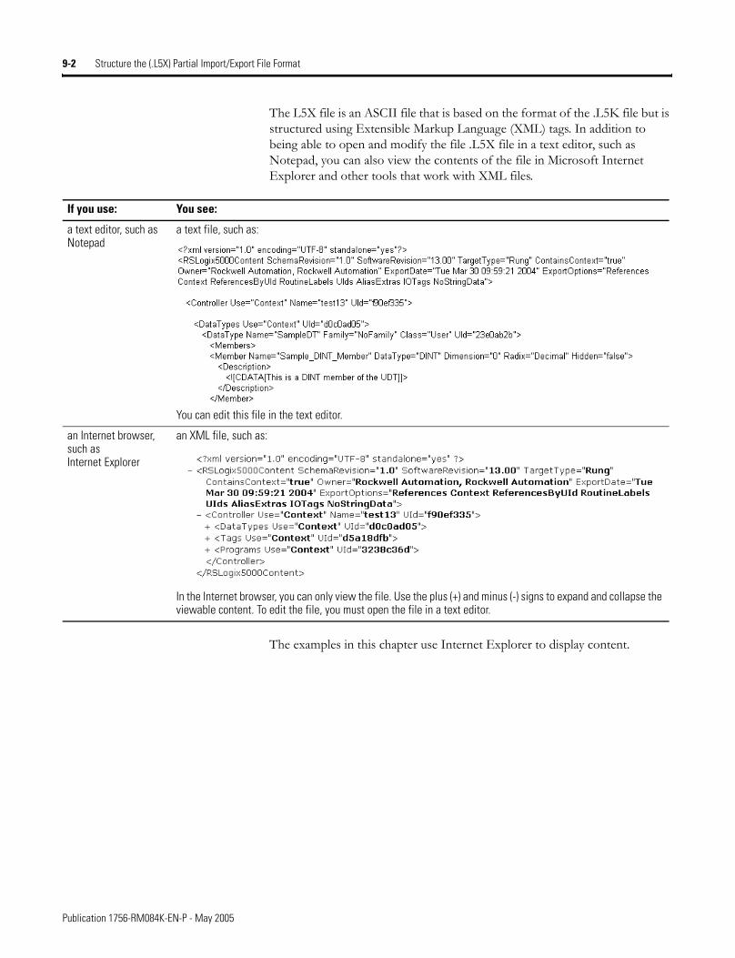
9-2 Structure the (.L5X) Partial Import/Export File Format
The L5X file is an ASCII file that is based on the format of the .L5K file but is structured using Extensible Markup Language (XML) tags. In addition to being able to open and modify the file .L5X file in a text editor, such as Notepad, you can also view the contents of the file in Microsoft Internet Explorer and other tools that work with XML files.
The examples in this chapter use Internet Explorer to display content.
If you use: You see:
a text editor, such as Notepad
a text file, such as:
You can edit this file in the text editor.
an Internet browser, such as Internet Explorer
an XML file, such as:
In the Internet browser, you can only view the file. Use the plus (+) and minus (-) signs to expand and collapse the viewable content. To edit the file, you must open the file in a text editor.
Publication 1756-RM084K-EN-P - May 2005
Structure the (.L5X) Partial Import/Export File Format 9-3
You can create .L5X files for:
Identify components in .L5X files
Each component in an .L5X file has an associated UID (unique identifier). This identifier is a combination of letters and numbers and it links the associated component of the file with some object that is defined earlier. For example a tag definition uses a UID to link to a user-defined structure that is defined earlier in the project. A single UID can be defined only once in an .L5X file. You cannot reuse the same UID to define two components in the same file.
RSLogix 5000 software creates UIDs to provide an abstraction layer between definitions and their respective names. For example, the instructions refer to a UID for the tags that they use. By doing this, the tag can be renamed without having to search and replace all of the logic references within the rungs.
UIDs are not optional. They are required for each component in an .L5X file. See the rest of this chapter for descriptions of the supported component types.
.L5X File: Description:
ladder rungs To create the .L5X file for ladder rungs:1. Select one or more rungs in a ladder routine.2. Right-click on the selected rungs and select Export Rungs.
The resulting .L5X files contains the rung logic, tag definitions, user-defined structures, and all associated descriptions.
To bring the contents of an .L5X file back into a projecT:1. Navigate to where you want to import the rungs in a ladder routine.2. Right-click and select Import Rungs.
When you import an .L5X file, RSLogix 5000 software provides a list of the tags and user-defined structures in the .L5X file and lets rename them and their associated descriptions prior to the import process.
trends You can also select a trend to export to an .L5X file:1. Select the trend icon in the Controller Organizer of the project.2. Right-click on the trend and select Export Trend.
The trend .L5X file just contains the configuration for the trend and its associated pens. It does not contain any tag definitions. If you import a trend, it will not operate correctly if its tags are not defined in the project.
To import a trend:1. Select the trend icon in the Controller Organizer of the project.2. Right-click on the trend and select Import Trend.
Publication 1756-RM084K-EN-P - May 2005
9-4 Structure the (.L5X) Partial Import/Export File Format
Place Information in a Ladder Rung .L5X File
The .L5X file for ladder rungs contains these components:
The ladder rung file uses this structure:
where:
The first part of the .L5X file is the header that defines the version of the import/export feature. Following the header is the Controller component, which is the overall structure for an .L5X file.
Component: Identifies:
CONTROLLER name of the controller
DATATYPE user-defined and I/O data structures
MODULE modules in the controller organizer
TAG controller-scope tags
PROGRAM program files and program-scope tags
Controller Item: Identifies:
Use the use of the controller project
specify “Context” or “Target”
Name the name of the controller project
UID the controller project with a unique combination of numbers and letters
Component Item: Contains:
DataTypes data type definitions
Modules I/O module definitions
Tags tag definitions
Programs program and routine(s) containing the rung logic
Publication 1756-RM084K-EN-P - May 2005
Structure the (.L5X) Partial Import/Export File Format 9-5
Define a DataType Component
The DataType component defines the data types used in the section of rungs you export. The DataType component uses this structure:
Specify a DataType
Each data type declaration within this component defines a data type and the members of that data type. Repeat this structure for each data type.
where:
Controller Item: Identifies:
Name the name of the data type
Family specify StringFamily for a string data type
specify NoFamily for all other data types
Class type of data type
specify User for user-defined
UID the controller project with a unique combination of numbers and letters
Publication 1756-RM084K-EN-P - May 2005
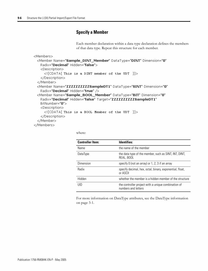
9-6 Structure the (.L5X) Partial Import/Export File Format
Specify a Member
Each member declaration within a data type declaration defines the members of that data type. Repeat this structure for each member.
where:
For more information on DataType attributes, see the DataType information on page 3-1.
Controller Item: Identifies:
Name the name of the member
DataType the data type of the member, such as SINT, INT, DINT, REAL, BOOL
Dimension specify 0 (not an array) or 1, 2, 3 if an array
Radix specify decimal, hex, octal, binary, exponential, float, or ASCII
Hidden whether the member is a hidden member of the structure
UID the controller project with a unique combination of numbers and letters
Publication 1756-RM084K-EN-P - May 2005
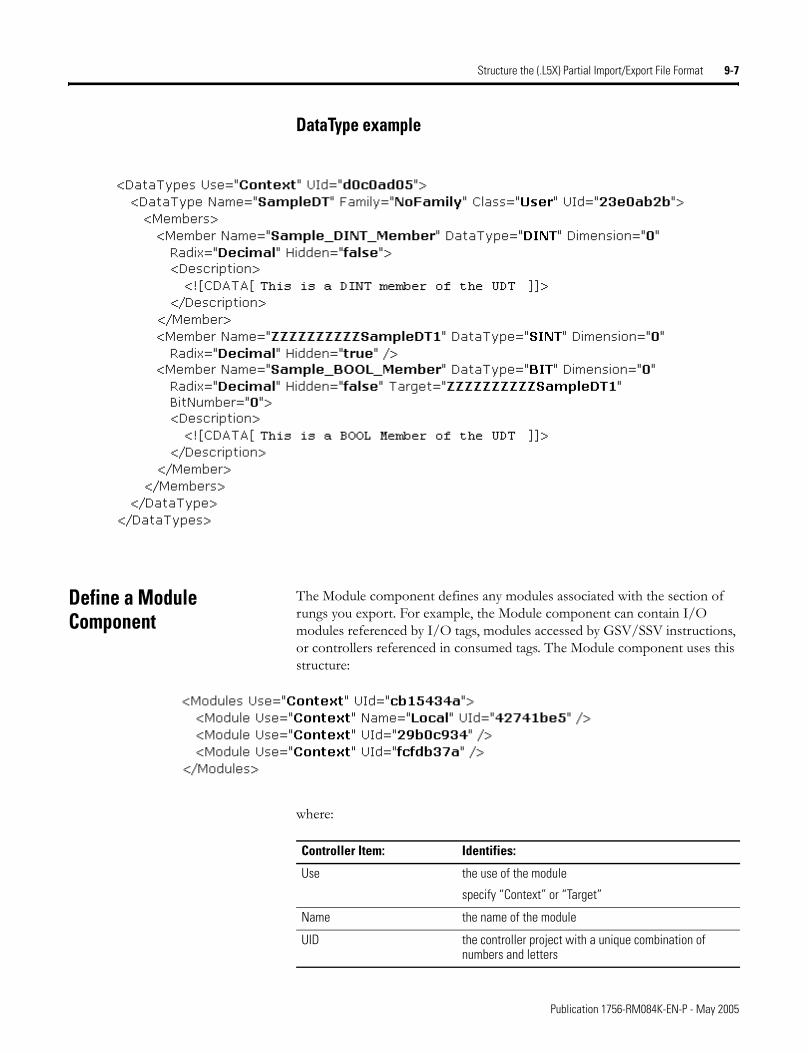
Structure the (.L5X) Partial Import/Export File Format 9-7
DataType example
Define a Module Component
The Module component defines any modules associated with the section of rungs you export. For example, the Module component can contain I/O modules referenced by I/O tags, modules accessed by GSV/SSV instructions, or controllers referenced in consumed tags. The Module component uses this structure:
where:
Controller Item: Identifies:
Use the use of the module
specify “Context” or “Target”
Name the name of the module
UID the controller project with a unique combination of numbers and letters
Publication 1756-RM084K-EN-P - May 2005
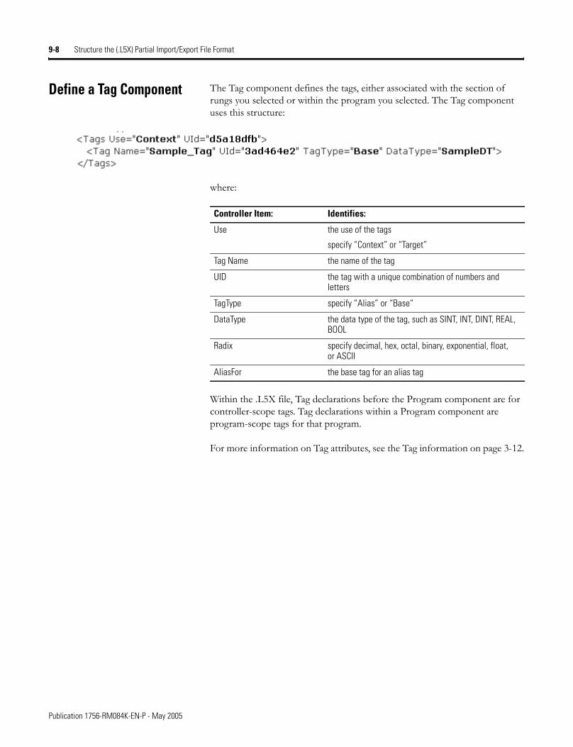
9-8 Structure the (.L5X) Partial Import/Export File Format
Define a Tag Component The Tag component defines the tags, either associated with the section of rungs you selected or within the program you selected. The Tag component uses this structure:
where:
Within the .L5X file, Tag declarations before the Program component are for controller-scope tags. Tag declarations within a Program component are program-scope tags for that program.
For more information on Tag attributes, see the Tag information on page 3-12.
Controller Item: Identifies:
Use the use of the tags
specify “Context” or “Target”
Tag Name the name of the tag
UID the tag with a unique combination of numbers and letters
TagType specify “Alias” or “Base“
DataType the data type of the tag, such as SINT, INT, DINT, REAL, BOOL
Radix specify decimal, hex, octal, binary, exponential, float, or ASCII
AliasFor the base tag for an alias tag
Publication 1756-RM084K-EN-P - May 2005
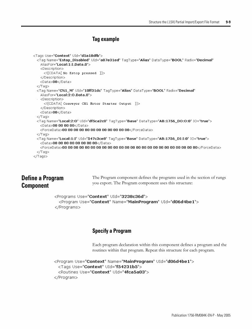
Structure the (.L5X) Partial Import/Export File Format 9-9
Tag example
Define a Program Component
The Program component defines the programs used in the section of rungs you export. The Program component uses this structure:
Specify a Program
Each program declaration within this component defines a program and the routines within that program. Repeat this structure for each program.
Publication 1756-RM084K-EN-P - May 2005
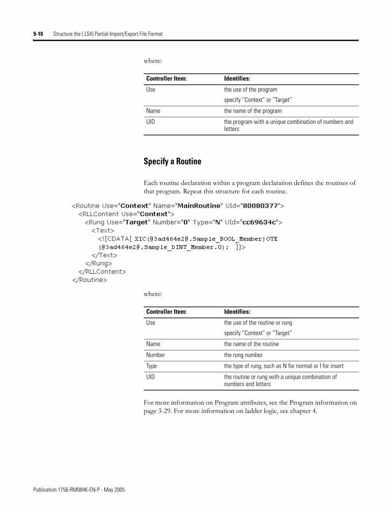
9-10 Structure the (.L5X) Partial Import/Export File Format
where:
Specify a Routine
Each routine declaration within a program declaration defines the routines of that program. Repeat this structure for each routine.
where:
For more information on Program attributes, see the Program information on page 3-29. For more information on ladder logic, see chapter 4.
Controller Item: Identifies:
Use the use of the program
specify “Context” or “Target”
Name the name of the program
UID the program with a unique combination of numbers and letters
Controller Item: Identifies:
Use the use of the routine or rung
specify “Context” or “Target”
Name the name of the routine
Number the rung number
Type the type of rung, such as N for normal or I for insert
UID the routine or rung with a unique combination of numbers and letters
Publication 1756-RM084K-EN-P - May 2005
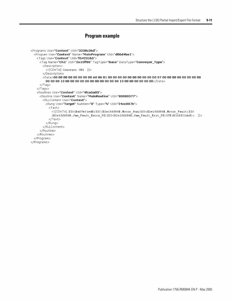
Structure the (.L5X) Partial Import/Export File Format 9-11
Program example
Publication 1756-RM084K-EN-P - May 2005
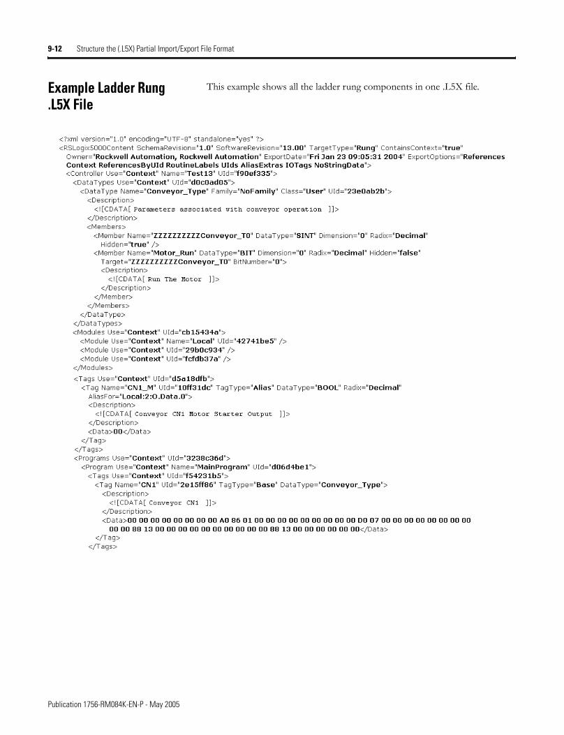
9-12 Structure the (.L5X) Partial Import/Export File Format
Example Ladder Rung .L5X File
This example shows all the ladder rung components in one .L5X file.
Publication 1756-RM084K-EN-P - May 2005
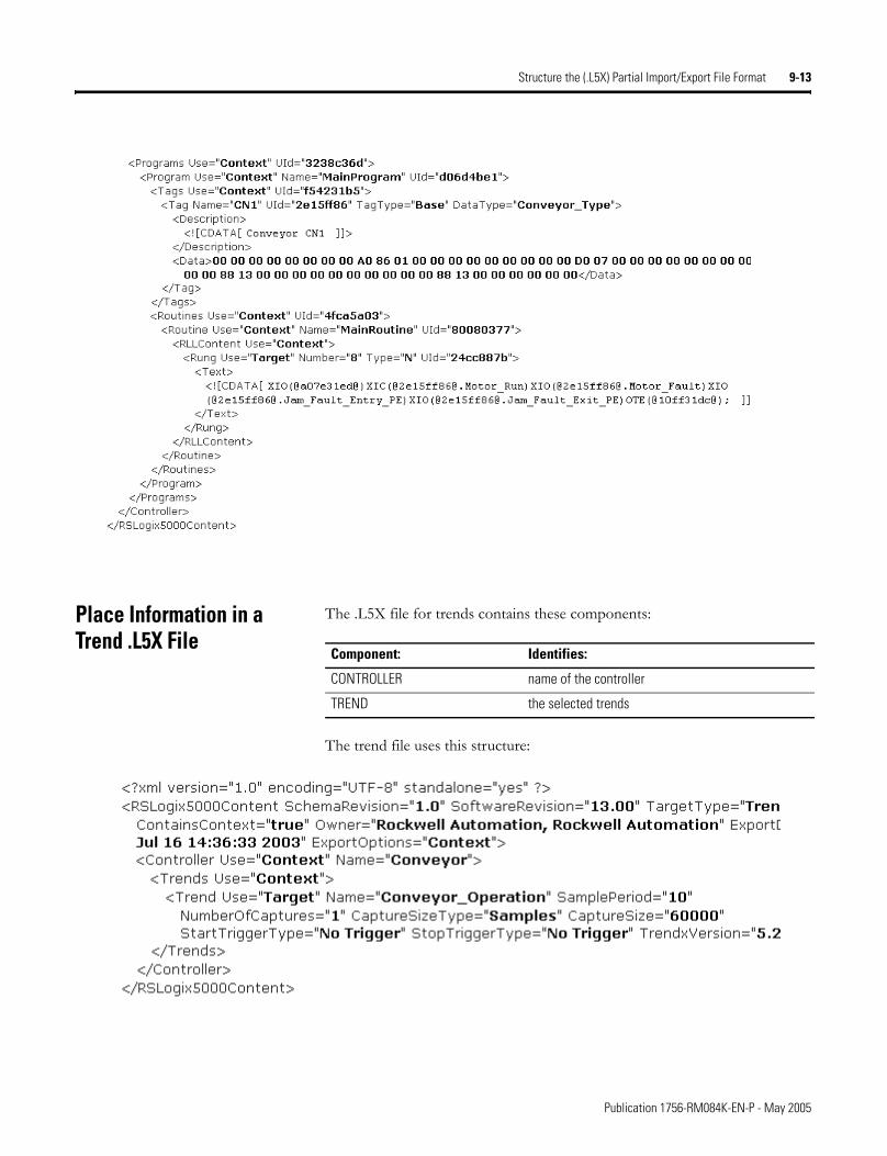
Structure the (.L5X) Partial Import/Export File Format 9-13
Place Information in a Trend .L5X File
The .L5X file for trends contains these components:
The trend file uses this structure:
Component: Identifies:
CONTROLLER name of the controller
TREND the selected trends
Publication 1756-RM084K-EN-P - May 2005
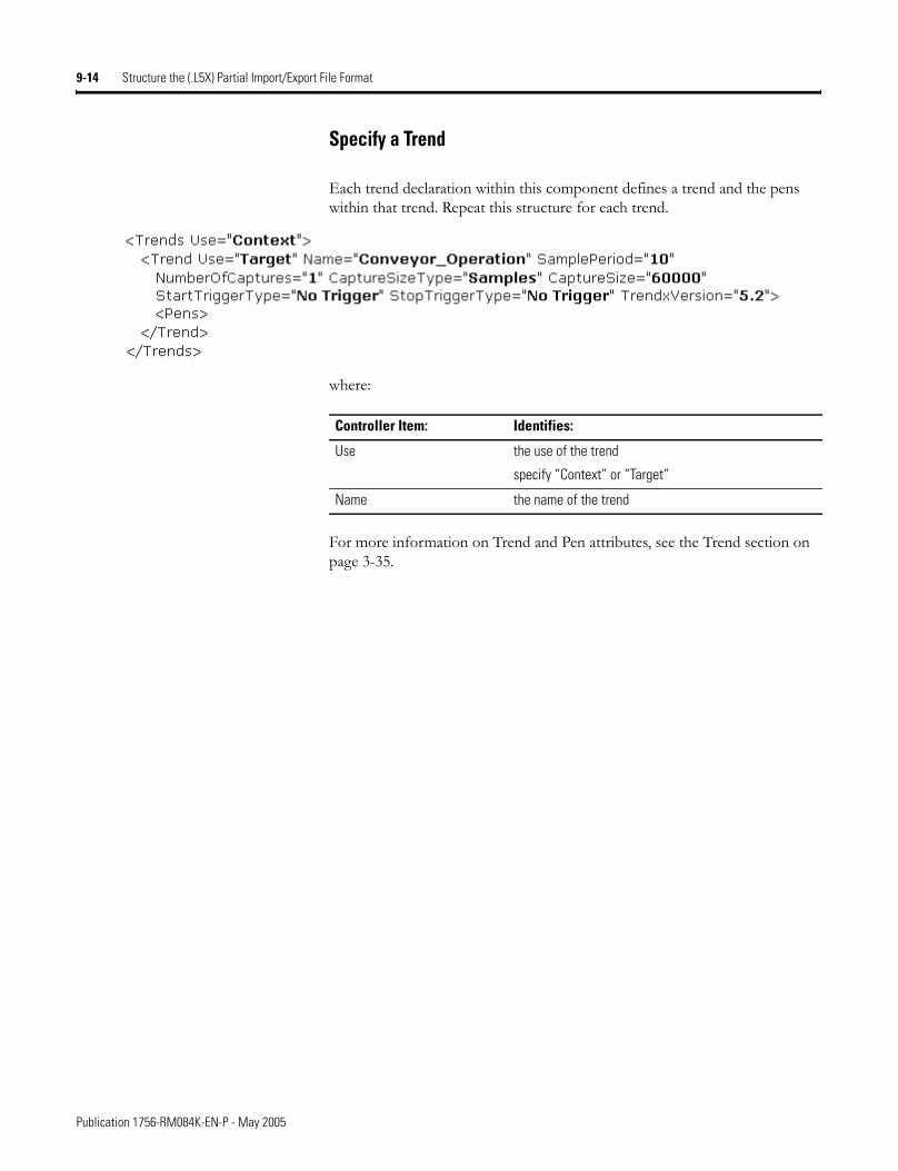
9-14 Structure the (.L5X) Partial Import/Export File Format
Specify a Trend
Each trend declaration within this component defines a trend and the pens within that trend. Repeat this structure for each trend.
where:
For more information on Trend and Pen attributes, see the Trend section on page 3-35.
Controller Item: Identifies:
Use the use of the trend
specify “Context” or “Target”
Name the name of the trend
Publication 1756-RM084K-EN-P - May 2005
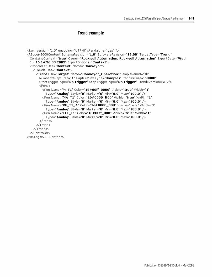
Structure the (.L5X) Partial Import/Export File Format 9-15
Trend example
Publication 1756-RM084K-EN-P - May 2005

9-16 Structure the (.L5X) Partial Import/Export File Format
Notes:
Publication 1756-RM084K-EN-P - May 2005
Appendix A
Considerations for Using Microsoft Excel to Edit a .CSV File
Introduction This appendix describes how using Microsoft Excel can affect a .CSV file.
Recommendations If you use Microsoft Excel to edit your .CSV tag file:
• Use single quotes instead of double quotes within descriptions and comments.
• Do not create descriptions or comments that consist only of numbers, have leading zeros, or have a leading symbol that Microsoft Excel treats specially. For example, do not create descriptions like:
002 +2 =2 -2 .0
• Do not create descriptions or comments that start with a +, -, or = symbol. Even if you add text after the symbol, Excel displays #NAME? in the cell.
IMPORTANT To edit the .CSV file, it is recommended that you use a database program tool, such as Microsoft Access, or a raw text editor. Many other desktop tools, such as Microsoft Word or Excel, might change the structure of the .CSV file and cause an import of the file to fail.
1 Publication 1756-RM084K-EN-P - May 2005
A-2 Considerations for Using Microsoft Excel to Edit a .CSV File
RSLogix 5000 Data Transformations
When RSLogix5000 programming software exports tags, it performs these conversions:
Microsoft Excel Data Transformation
When you open the exported .CSV file in Excel, these conversions occur:
Original content: Content in .CSV file after export:
‘ $’
“ $Q
newline $N$L
tab $T
$ $$
Original content:
Content in .CSV file after export:
Content after opening in Excel:
Content after saving from Excel:
Details:
.0 “.0” 0 0 RSLogix5000 addresses this as the specifier for a tag.If you enter this as an entire comment, you lose any preceding period (.). If you enter any text before or after this, Excel maintains the content.
=2 “=2” 2 2 If you enter this as an entire comment, you lose any preceding equal sign (=). If you enter any text before or after this, Excel maintains the content.
+2 “+2” 2 2 If you enter this as an entire comment, you lose any preceding plus sign (+). If you enter any text before or after this, Excel maintains the content.
002 “002” 2 2 If you enter this as an entire comment, you lose any preceding zeros. If you enter any text before or after this, Excel maintains the content.
test string “test string” test string test string Excel puts quotes around cell contents only if there is an embedded comma.RSLogix5000 always places double quotes around text. But RSLogix5000 can still handle the description without quotes.
“test string” “$”test string$”” $test string$”” “$test string$”””””
Both Excel and RSLogix5000 alter content when it includes a dollar sign ($).
has “quoted text” within string
“has $”quoted text$” within string”
has $quoted text$” within string”
“has $quoted text $”” within string”””
Both Excel and RSLogix5000 alter content when it includes a dollar sign ($).
this has ‘embedded’ text
this has $’embedded$’ text
this has $’embedded$’ text
this has $’embedded$’ text
Single quotes work fine in both software packages.
Publication 1756-RM084K-EN-P - May 2005
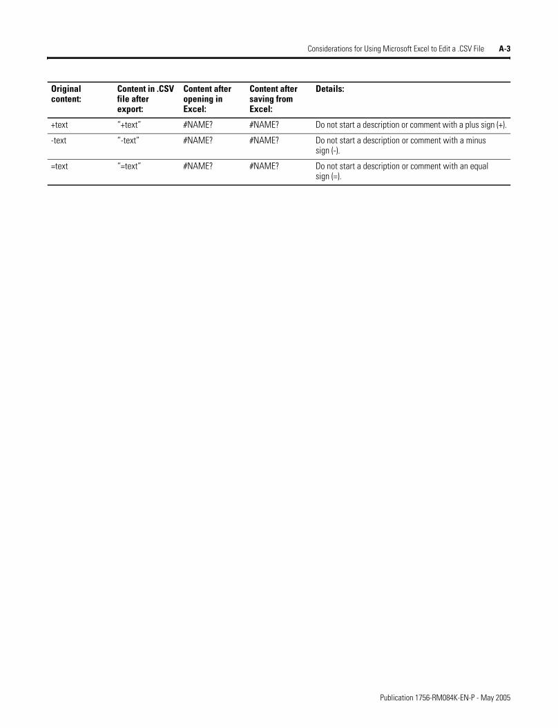
Considerations for Using Microsoft Excel to Edit a .CSV File A-3
+text “+text” #NAME? #NAME? Do not start a description or comment with a plus sign (+).
-text “-text” #NAME? #NAME? Do not start a description or comment with a minus sign (-).
=text “=text” #NAME? #NAME? Do not start a description or comment with an equal sign (=).
Original content:
Content in .CSV file after export:
Content after opening in Excel:
Content after saving from Excel:
Details:
Publication 1756-RM084K-EN-P - May 2005

A-4 Considerations for Using Microsoft Excel to Edit a .CSV File
Notes:
Publication 1756-RM084K-EN-P - May 2005
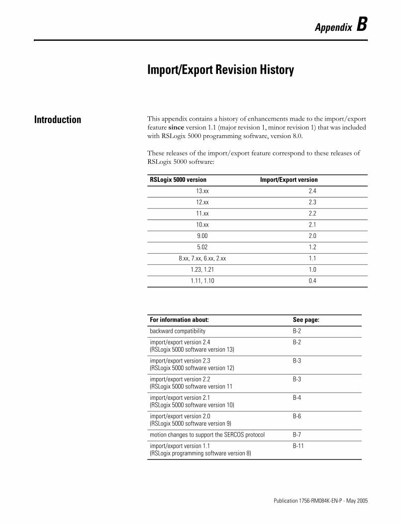
Appendix B
Import/Export Revision History
Introduction This appendix contains a history of enhancements made to the import/export feature since version 1.1 (major revision 1, minor revision 1) that was included with RSLogix 5000 programming software, version 8.0.
These releases of the import/export feature correspond to these releases of RSLogix 5000 software:
RSLogix 5000 version Import/Export version
13.xx 2.4
12.xx 2.3
11.xx 2.2
10.xx 2.1
9.00 2.0
5.02 1.2
8.xx, 7.xx, 6.xx, 2.xx 1.1
1.23, 1.21 1.0
1.11, 1.10 0.4
For information about: See page:
backward compatibility B-2
import/export version 2.4(RSLogix 5000 software version 13)
B-2
import/export version 2.3(RSLogix 5000 software version 12)
B-3
import/export version 2.2(RSLogix 5000 software version 11
B-3
import/export version 2.1(RSLogix 5000 software version 10)
B-4
import/export version 2.0(RSLogix 5000 software version 9)
B-6
motion changes to support the SERCOS protocol B-7
import/export version 1.1(RSLogix programming software version 8)
B-11
1 Publication 1756-RM084K-EN-P - May 2005
B-2 Import/Export Revision History
Backward Compatibility The import/export feature supports backward compatibility for import operations. This means that the RSLogix 5000 programming software can import .L5K files that were generated by a previous version of the programming software. In some cases, an older .L5K file might not correctly import into newer version of the programming software. The revision history in this appendix will list any conditions when backward compatibility for an import operation does not work as expected.
The import/export feature does not support backward compatibility for export operations. This means that older version of the RSLogix 5000 programming software cannot read .L5K files that were created with newer versions of the programming software.
Each version of the RSLogix 5000 programming software exports .L5K files with a specific import/export version number. The RSLogix 5000 programming software imports any .L5K file with the same major revision number and the same or lower minor revision number. The major revision number increments when there are conditions such that the programming software cannot support backward compatibility for import operations. The minor revision number increments whenever there is a change in the file (a new module, an attribute is added, the set of options for an attribute is changed, etc.) that does not affect backward compatibility for import operations.
Import/Export Version 2.4 RSLogix 5000 Version 13
Version 2.4 (major revision 2, minor revision 4) of the import/export feature that is included with RSLogix 5000 programming software, version 13 included these major enhancements:
• Support for new controllers.• ExtendedProp section to MODULE data.• Support for new TAG attributes.
Attributes can be in any order in an import/export file. The order shown in this document is the order the attributes export.
• Support for a TREND object in the import/export .L5K file.• New MCSV instruction in ladder logic (chapter 4) and structured text.• Online editing support for structured text and sequential function chart
logic.• Updated CSV format now includes rung comments.• New .L5X format for partial import/export of ladder rungs, tags, and
trends.
IMPORTANT Be careful when copying and pasting between different versions of .L5K files. Do not paste objects from an older .L5K file into a newer version.
Publication 1756-RM084K-EN-P - May 2005
Import/Export Revision History B-3
Import/Export Version 2.3 RSLogix 5000 Version 12
Version 2.3 (major revision 2, minor revision 3) of the import/export feature that is included with RSLogix 5000 programming software, version 12.01 included these major enhancements:
• The structured text component changed from STX_ROUTINE to ST_ROUTINE. The LanguageType attribute in SFC routines for embedded structured text also changed from STX to ST.
• Support for new controllers.• Addition of the ControlNetSignature attribute to the MODULE
component.• Addition of the ProgrammaticallySendEventTrigger attribute to the
TAG component.• New COORDINATE_SYSTEM tag.• Addition of several new attributes to the axis tag types.• Addition of DisableFlag attribute to the PROGRAM component.• Addition of EventTrigger and EventTag attributes to the TASK
component to support Event tasks.• New EVENT, IOT, MCCD, MCCM, MCLM, MCS, MCSD, and MCSR
instructions in ladder logic and structured text.• Addition of information regarding the LOGIC block when exporting
online function block logic.• Addition of new modules and their valid CommMethod and
ConfigMethod values.
Import/Export Version 2.2 RSlogix 5000 Version 11
Version 2.2 (major revision 2, minor revision 2) of the import/export feature that is included with RSLogix 5000 programming software, version 11.10 included these major enhancements:
• Support for the 1756-L63 controller.• New controller attributes to support sequential function charts.• Corrected the DATATYPE attributes and added the FamilyType
attribute.• Additional information for the CompatibleModule and KeyMask
attributes of the MODULE component.• Addition of RSNetWorxFileName attribute to the MODULE
component.• Addition of SFC_ACTION, SFC_STEP, and SFC_STOP tag types.• Addition of 38400 as a supported serial port baud rate.• Addition of structured text instructions.• Addition of EOT, SFR, and SFP instructions to relay ladder and
structured text.• Addition of sequential function chart components.• Addition of an appendix that lists the valid CommMethod and
ConfigMethod values for the supported I/O modules.
Publication 1756-RM084K-EN-P - May 2005
B-4 Import/Export Revision History
Beginning with version 2.2, multi-line rung comments (with hard returns) are no longer exported as one long string (in double-quotes). Instead, each line of a multi-line rung comment is on a separate line in the .L5K file with double-quotes around each line. When imported, the multiple quoted strings are concatenated to form the rung comment. This improves the readability of the .L5K text file using the existing multiple-string capability of the rung comment syntax. Older formats still work on import.
Import/Export Version 2.1 RSLogix 5000 Version 10
Version 2.1 (major revision 2, minor revision 1) of the import/export feature that is included with RSLogix 5000 programming software, version 10.0 included these major enhancements:
• Removal of the characters /A when specifying a controller type.• Addition of the SecurityCode atttribute to the Controller object.• Enhancments to the Message tag structure (see page B-4).• The Program object now includes a Mode attribute.• Correction to valid values for Watchdog and Rate attributes of the
Task object.• Addition of MaxStationAddress and TokenHoldFactor attributes to the
Config DF1 object.• Addition of new instructions: SIZE, SWPB, LOWER, and UPPER.• The NumberOfAppendChars of the Config ASCII object is no longer
exported. If you have an import/export file with any of these attributes, the file will correctly import into the software. This attributes will be removed when you later export the file.
Changes to support MESSAGE tag enhancements
Version 2.1 (major revision 2, minor revision 1) of the import/export feature that is included with RSLogix 5000 programming software, version 10.0 made significant changes to the MESSAGE tag. For reference, the following table shows the MESSAGE tag structure of the previous import/export release.
Publication 1756-RM084K-EN-P - May 2005
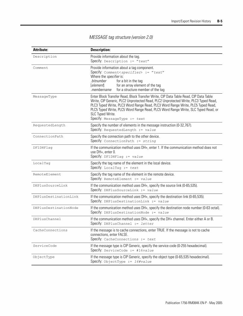
Import/Export Revision History B-5
MESSAGE tag structure (version 2.0)
Attribute: Description:
Description Provide information about the tag.Specify: Description := �text�
Comment Provide information about a tag component.Specify: Comment<specifier> := �text�Where the specifier is:.bitnumber for a bit in the tag[element] for an array element of the tag .membername for a structure member of the tag
MessageType Enter Block Transfer Read, Block Transfer Write, CIP Data Table Read, CIP Data Table Write, CIP Generic, PLC2 Unprotected Read, PLC2 Unprotected Write, PLC3 Typed Read, PLC3 Typed Write, PLC3 Word Range Read, PLC3 Word Range Write, PLC5 Typed Read, PLC5 Typed Write, PLC5 Word Range Read, PLC5 Word Range Write, SLC Typed Read, or SLC Typed Write.Specify: MessageType := text
RequestedLength Specify the number of elements in the message instruction (0-32,767).Specify: RequestedLength := value
ConnectionPath Specify the connection path to the other device.Specify: ConnectionPath := string
DF1DHFlag If the communication method uses DH+, enter 1. If the communication method does not use DH+, enter 0.Specify: DF1DHFlag := value
LocalTag Specify the tag name of the element in the local device.Specify: LocalTag := text
RemoteElement Specify the tag name of the element in the remote device.Specify: RemoteElement := value
DHPlusSourceLink If the communication method uses DH+, specify the source link (0-65,535).Specify: DHPlusSourceLink := value
DHPlusDestinationLink If the communication method uses DH+, specify the destination link (0-65,535).Specify: DHPlusDestinationLink := value
DHPlusDestinationNode If the communication method uses DH+, specify the destination node number (0-63 octal).Specify: DHPlusDestinationNode := value
DHPlusChannel If the communication method uses DH+, specify the DH+ channel. Enter either A or B.Specify: DHPlusChannel := letter
CacheConnections If the message is to cache connections, enter TRUE. If the message is not to cache connections, enter FALSE.Specify: CacheConnections := text
ServiceCode If the message type is CIP Generic, specify the service code (0-255 hexadecimal).Specify: ServiceCode := #16value
ObjectType If the message type is CIP Generic, specify the object type (0-65,535 hexadecimal).Specify: ObjectType := 16#value
Publication 1756-RM084K-EN-P - May 2005
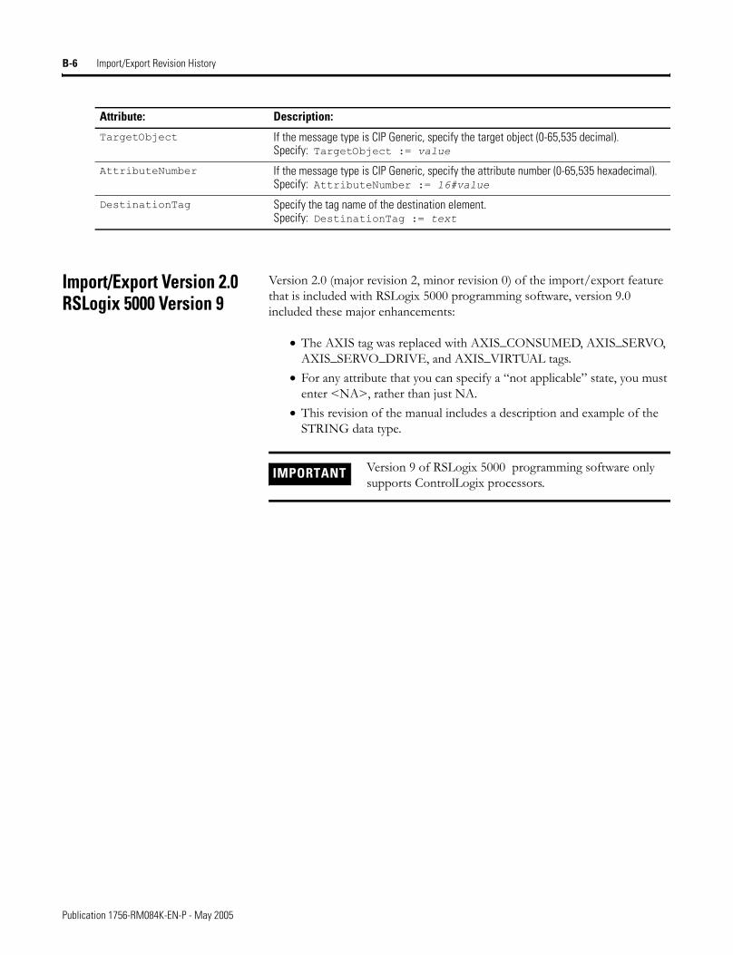
B-6 Import/Export Revision History
Import/Export Version 2.0 RSLogix 5000 Version 9
Version 2.0 (major revision 2, minor revision 0) of the import/export feature that is included with RSLogix 5000 programming software, version 9.0 included these major enhancements:
• The AXIS tag was replaced with AXIS_CONSUMED, AXIS_SERVO, AXIS_SERVO_DRIVE, and AXIS_VIRTUAL tags.
• For any attribute that you can specify a �not applicable� state, you must enter <NA>, rather than just NA.
• This revision of the manual includes a description and example of the STRING data type.
TargetObject If the message type is CIP Generic, specify the target object (0-65,535 decimal).Specify: TargetObject := value
AttributeNumber If the message type is CIP Generic, specify the attribute number (0-65,535 hexadecimal).Specify: AttributeNumber := 16#value
DestinationTag Specify the tag name of the destination element.Specify: DestinationTag := text
Attribute: Description:
IMPORTANT Version 9 of RSLogix 5000 programming software only supports ControlLogix processors.
Publication 1756-RM084K-EN-P - May 2005
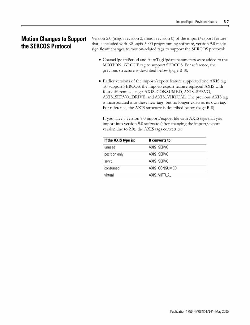
Import/Export Revision History B-7
Motion Changes to Support the SERCOS Protocol
Version 2.0 (major revision 2, minor revision 0) of the import/export feature that is included with RSLogix 5000 programming software, version 9.0 made significant changes to motion-related tags to support the SERCOS protocol:
• CoarseUpdatePeriod and AutoTagUpdate parameters were added to the MOTION_GROUP tag to support SERCOS. For reference, the previous structure is described below (page B-8).
• Earlier versions of the import/export feature supported one AXIS tag. To support SERCOS, the import/export feature replaced AXIS with four different axis tags: AXIS_CONSUMED, AXIS_SERVO, AXIS_SERVO_DRIVE, and AXIS_VIRTUAL. The previous AXIS tag is incorporated into these new tags, but no longer exists as its own tag. For reference, the AXIS structure is described below (page B-8).
If you have a version 8.0 import/export file with AXIS tags that you import into version 9.0 software (after changing the import/export version line to 2.0), the AXIS tags convert to:
If the AXIS type is: It converts to:
unused AXIS_SERVO
position only AXIS_SERVO
servo AXIS_SERVO
consumed AXIS_CONSUMED
virtual AXIS_VIRTUAL
Publication 1756-RM084K-EN-P - May 2005
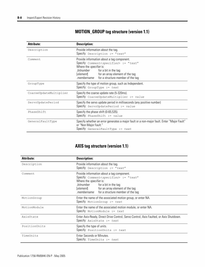
B-8 Import/Export Revision History
MOTION_GROUP tag structure (version 1.1)
AXIS tag structure (version 1.1)
Attribute: Description:
Description Provide information about the tag.Specify: Description := �text�
Comment Provide information about a tag component.Specify: Comment<specifier> := �text�Where the specifier is:.bitnumber for a bit in the tag[element] for an array element of the tag .membername for a structure member of the tag
GroupType Specify the type of motion group, such as Independent.Specify: GroupType := text
CoarseUpdateMultiplier Specify the coarse update rate (5-320ms).Specify: CoarseUpdateMultiplier := value
ServoUpdatePeriod Specify the servo update period in milliseconds (any positive number)Specify: ServoUpdatePeriod := value
PhaseShift Specify the phase shift (0-65,535).Specify: PhaseShift := value
GeneralFaultType Specify whether an error generates a major fault or a non-major fault. Enter “Major Fault” or “Non Major Fault.”Specify: GeneralFaultType := text
Attribute: Description:
Description Provide information about the tag.Specify: Description := �text�
Comment Provide information about a tag component.Specify: Comment<specifier> := �text�Where the specifier is:.bitnumber for a bit in the tag[element] for an array element of the tag .membername for a structure member of the tag
MotionGroup Enter the name of the associated motion group, or enter NA.Specify: MotionGroup := text
MotionModule Enter the name of the associated motion module, or enter NA.Specify: MotionModule := text
AxisState Enter Axis-Ready, Direct Drive Control, Servo Control, Axis Faulted, or Axis Shutdown.Specify: AxisState := text
PositionUnits Specify the type of units.Specify: PositionUnits := text
TimeUnits Enter Seconds or Minutes.Specify: TimeUnits := text
Publication 1756-RM084K-EN-P - May 2005
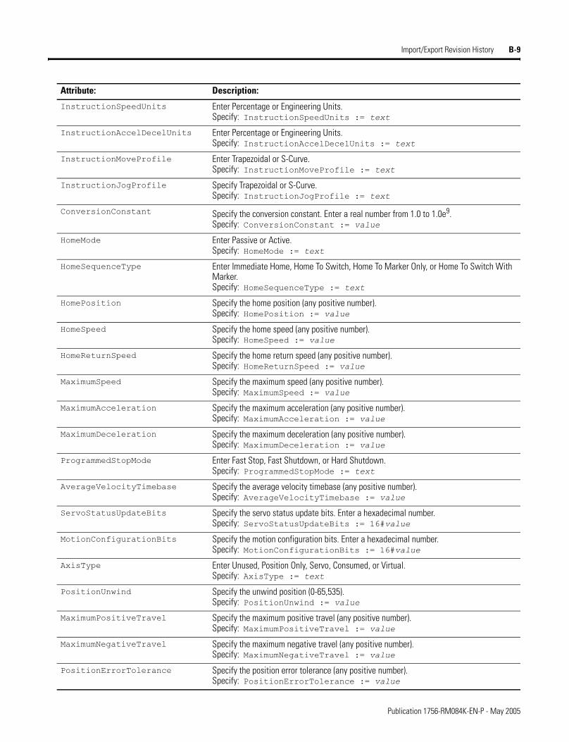
Import/Export Revision History B-9
InstructionSpeedUnits Enter Percentage or Engineering Units.Specify: InstructionSpeedUnits := text
InstructionAccelDecelUnits Enter Percentage or Engineering Units.Specify: InstructionAccelDecelUnits := text
InstructionMoveProfile Enter Trapezoidal or S-Curve.Specify: InstructionMoveProfile := text
InstructionJogProfile Specify Trapezoidal or S-Curve.Specify: InstructionJogProfile := text
ConversionConstant Specify the conversion constant. Enter a real number from 1.0 to 1.0e9.Specify: ConversionConstant := value
HomeMode Enter Passive or Active.Specify: HomeMode := text
HomeSequenceType Enter Immediate Home, Home To Switch, Home To Marker Only, or Home To Switch With Marker.Specify: HomeSequenceType := text
HomePosition Specify the home position (any positive number).Specify: HomePosition := value
HomeSpeed Specify the home speed (any positive number).Specify: HomeSpeed := value
HomeReturnSpeed Specify the home return speed (any positive number).Specify: HomeReturnSpeed := value
MaximumSpeed Specify the maximum speed (any positive number).Specify: MaximumSpeed := value
MaximumAcceleration Specify the maximum acceleration (any positive number).Specify: MaximumAcceleration := value
MaximumDeceleration Specify the maximum deceleration (any positive number).Specify: MaximumDeceleration := value
ProgrammedStopMode Enter Fast Stop, Fast Shutdown, or Hard Shutdown.Specify: ProgrammedStopMode := text
AverageVelocityTimebase Specify the average velocity timebase (any positive number).Specify: AverageVelocityTimebase := value
ServoStatusUpdateBits Specify the servo status update bits. Enter a hexadecimal number.Specify: ServoStatusUpdateBits := 16#value
MotionConfigurationBits Specify the motion configuration bits. Enter a hexadecimal number.Specify: MotionConfigurationBits := 16#value
AxisType Enter Unused, Position Only, Servo, Consumed, or Virtual.Specify: AxisType := text
PositionUnwind Specify the unwind position (0-65,535).Specify: PositionUnwind := value
MaximumPositiveTravel Specify the maximum positive travel (any positive number).Specify: MaximumPositiveTravel := value
MaximumNegativeTravel Specify the maximum negative travel (any positive number).Specify: MaximumNegativeTravel := value
PositionErrorTolerance Specify the position error tolerance (any positive number).Specify: PositionErrorTolerance := value
Attribute: Description:
Publication 1756-RM084K-EN-P - May 2005
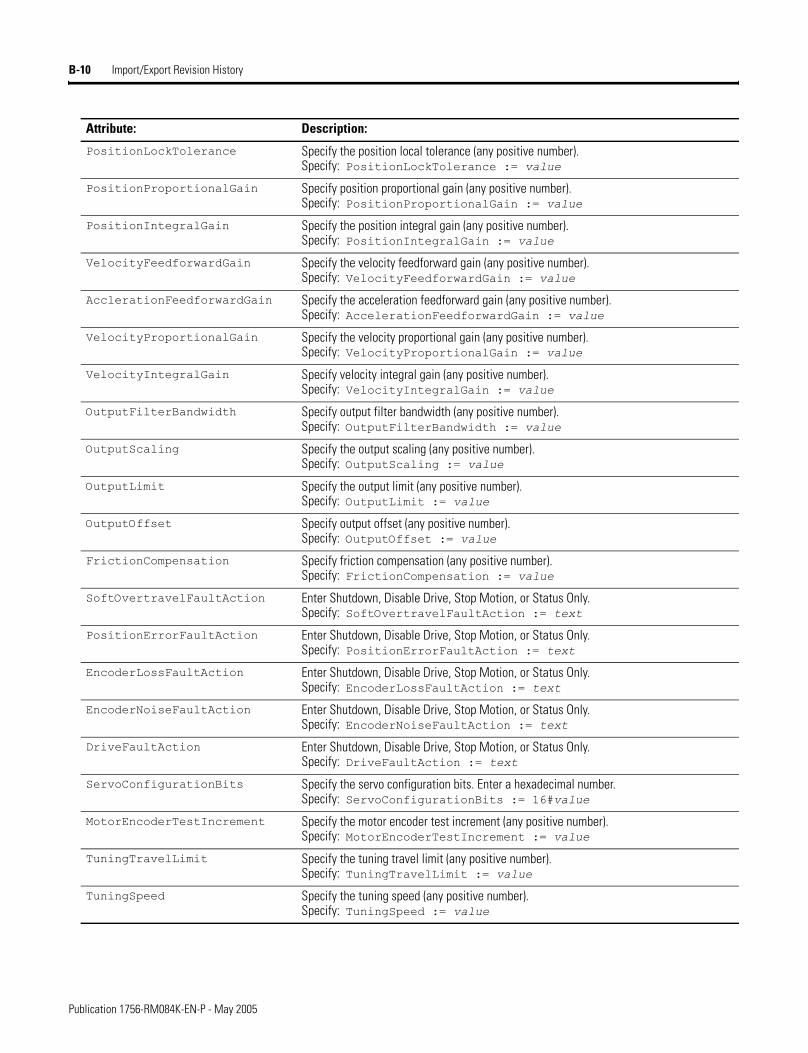
B-10 Import/Export Revision History
PositionLockTolerance Specify the position local tolerance (any positive number).Specify: PositionLockTolerance := value
PositionProportionalGain Specify position proportional gain (any positive number).Specify: PositionProportionalGain := value
PositionIntegralGain Specify the position integral gain (any positive number).Specify: PositionIntegralGain := value
VelocityFeedforwardGain Specify the velocity feedforward gain (any positive number).Specify: VelocityFeedforwardGain := value
AcclerationFeedforwardGain Specify the acceleration feedforward gain (any positive number).Specify: AccelerationFeedforwardGain := value
VelocityProportionalGain Specify the velocity proportional gain (any positive number).Specify: VelocityProportionalGain := value
VelocityIntegralGain Specify velocity integral gain (any positive number).Specify: VelocityIntegralGain := value
OutputFilterBandwidth Specify output filter bandwidth (any positive number).Specify: OutputFilterBandwidth := value
OutputScaling Specify the output scaling (any positive number).Specify: OutputScaling := value
OutputLimit Specify the output limit (any positive number).Specify: OutputLimit := value
OutputOffset Specify output offset (any positive number).Specify: OutputOffset := value
FrictionCompensation Specify friction compensation (any positive number).Specify: FrictionCompensation := value
SoftOvertravelFaultAction Enter Shutdown, Disable Drive, Stop Motion, or Status Only.Specify: SoftOvertravelFaultAction := text
PositionErrorFaultAction Enter Shutdown, Disable Drive, Stop Motion, or Status Only.Specify: PositionErrorFaultAction := text
EncoderLossFaultAction Enter Shutdown, Disable Drive, Stop Motion, or Status Only.Specify: EncoderLossFaultAction := text
EncoderNoiseFaultAction Enter Shutdown, Disable Drive, Stop Motion, or Status Only.Specify: EncoderNoiseFaultAction := text
DriveFaultAction Enter Shutdown, Disable Drive, Stop Motion, or Status Only.Specify: DriveFaultAction := text
ServoConfigurationBits Specify the servo configuration bits. Enter a hexadecimal number.Specify: ServoConfigurationBits := 16#value
MotorEncoderTestIncrement Specify the motor encoder test increment (any positive number).Specify: MotorEncoderTestIncrement := value
TuningTravelLimit Specify the tuning travel limit (any positive number).Specify: TuningTravelLimit := value
TuningSpeed Specify the tuning speed (any positive number).Specify: TuningSpeed := value
Attribute: Description:
Publication 1756-RM084K-EN-P - May 2005
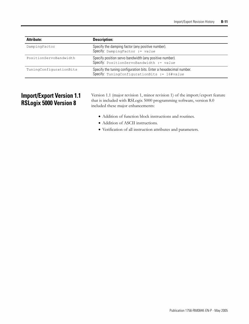
Import/Export Revision History B-11
Import/Export Version 1.1 RSLogix 5000 Version 8
Version 1.1 (major revision 1, minor revision 1) of the import/export feature that is included with RSLogix 5000 programming software, version 8.0 included these major enhancements:
• Addition of function block instructions and routines.• Addition of ASCII instructions.• Verification of all instruction attributes and parameters.
DampingFactor Specify the damping factor (any positive number).Specify: DampingFactor := value
PositionServoBandwidth Specify position servo bandwidth (any positive number).Specify: PositionServoBandwidth := value
TuningConfigurationBits Specify the tuning configuration bits. Enter a hexadecimal number.Specify: TuningConfigurationBits := 16#value
Attribute: Description:
Publication 1756-RM084K-EN-P - May 2005

B-12 Import/Export Revision History
Notes:
Publication 1756-RM084K-EN-P - May 2005
Index
AACTION_LIST block 7-13aliases 3-13array specifications 3-14ATTACHMENT
entering 7-23example 7-23guidelines 7-23
attachments 7-23attributes
AXIS_CONSUMED TAG 3-17AXIS_SERVO TAG 3-17AXIS_SERVO_DRIVE TAG 3-17AXIS_VIRTUAL TAG 3-17CONTROLLER 2-5COORDINATE_SYSTEM TAG 3-26DATATYPE 3-2EquipmentPhase PROGRAM 3-31FBD_ROUTINE 5-2MESSAGE TAG 3-16MODULE 3-5MOTION_GROUP TAG 3-15PEN declaration 3-40PROGRAM 3-30ROUTINE 4-1SFC_ROUTINE 7-3ST_ROUTINE 6-1TAG 3-14TASK 3-33, 3-43TREND 3-36
AXIS_CONSUMED TAG 3-17AXIS_SERVO TAG 3-17AXIS_SERVO_DRIVE TAG 3-17AXIS_VIRTUAL TAG 3-17
Bbackward compatibility B-2BLOCK
component 5-11guidelines 5-12
block 7-13BRANCH
entering 7-19example 7-20LEG block 7-20
branches 4-3, 7-19
CCOMMENT
record 8-4comments 8-1
CSV format 8-1internal file 2-1rung logic 4-4structured text logic 6-3TAG 3-28
completebranches 4-3comments 2-1components 2-2CONFIG 3-43connection list 3-8CONTROLLER 2-4conventions 2-1DATATYPE 3-1display style 2-3FBD_ROUTINE 5-1file format 3-1function block logic 5-2MODULE 3-5PROGRAM 3-29ROUTINE 4-1rung logic 4-2sequential function chart logic 7-1SFC_ROUTINE 7-1ST_ROUTINE 6-1structure 2-2structured text logic 6-2TAG 3-12TASK 3-33TREND 3-35
complete import/export 1-2, 1-3components
basic format 2-2BLOCK 5-11CONFIG 3-43CONTROLLER 2-4DATATYPE 3-1DataType 9-5descriptions 2-3display style 2-3FBD_ROUTINE 5-1ICON 5-9IREF 5-7MODULE 3-5
Publication 1756-RM084K-EN-P - May 2005
2
components (continued)Module 9-7OCON 5-9OREF 5-7PROGRAM 3-29Program 9-9ROUTINE 4-1SFC_ROUTINE 7-1ST_ROUTINE 6-1TAG 3-12Tag 9-8TASK 3-33TREND 3-35Trend 9-13WIRE 5-10
CONDITION block 7-16CONFIG
component 3-43examples 3-48
connection list 3-8CONTROLLER
attributes 2-5component 2-4example 2-6guidelines 2-6
controller objects 3-43conventions 2-1COORDINATE_SYSTEM TAG 3-26CSV format 1-5, A-1
examples 8-5
DDATATYPE
attributes 3-2component 3-1example 3-4guidelines 3-4
DataTypecomponent 9-5
descriptions 2-3dimensions 3-14directed links 7-21DIRECTED_LINK
entering 7-21example 7-21guidelines 7-21
display style 2-3
Eentering
attachments 7-23branches 7-19directed links 7-21steps 7-11stops 7-18subroutine calls 7-17text boxes 7-22transitions 7-15
EquipmentPhase PROGRAM 3-31examples
ATTACHMENT 7-23BRANCH 7-20CONFIG 3-48CONTROLLER 2-6CSV files 8-5DATATYPE 3-4DIRECTED_LINK 7-21EquipmentPhase PROGRAM 3-32function block logic 5-4ICON 5-10IREF 5-8LOGIC 5-6, 6-4, 7-9MODULE 3-10OCON 5-10online fsequential function chart logic 7-9online function block logic 5-6online structured text logic 6-4OREF 5-8PROGRAM 3-32ROUTINE 4-3rung logic 4-4SBR_RET 7-18sequential function chart logic 7-4SFC_ROUTINE 7-4SHEET 5-4ST_ROUTINE 6-3STEP 7-15STOP 7-19TAG 3-29TASK 3-35TEXT_BOX 7-22TRANSITION 7-17TREND 3-42WIRE 5-11
Excel A-1
Publication 1756-RM084K-EN-P - May 2005
3
exportingcomplete project 1-2CSV format 1-5file structure 2-2, 9-4L5K format 1-2L5X format 1-8ladder rungs 1-8partial project 1-5, 1-8project 1-2tags 1-5, 1-8trends 1-8, 3-41types 1-1
FFBD_ROUTINE
attributes 5-2BLOCK logic 5-11component 5-1example 5-4ICON logic 5-9IREF logic 5-7LOGIC block 5-6OCON logic 5-9OREF logic 5-7SHEET logic 5-3WIRE logic 5-10
formatCSV 8-1L5K 2-1, 3-1L5X 3-41, 9-1
function block logic 5-2online edits 5-6
Gguidelines
ATTACHMENT 7-23BLOCK logic 5-12CONTROLLER 2-6DATATYPE 3-4DIRECTED_LINK 7-21ICON logic 5-9IREF logic 5-8MODULE 3-9OCON 5-9OREF logic 5-8PROGRAM 3-31rung logic 4-2SHEET logic 5-3
guidelines (continued)TAG 3-28TASK 3-34TEXT_BOX 7-22TREND 3-41WIRE logic 5-11
Hhistory, import/export feature B-1
IICON
component 5-9example 5-10guidelines 5-9
importingcomplete project 1-3CSV format 1-6file structure 2-2, 9-4L5K format 1-3L5X format 1-9ladder rungs 1-9partial project 1-6, 1-9project 1-3tags 1-6, 1-9trends 1-9types 1-1
initial values 3-27instructions 4-4, 5-13, 6-5internal file comments 2-1, 8-1IREF
component 5-7example 5-8guidelines 5-8
LL5K format 2-1, 3-1L5X format 1-8, 3-41, 9-1LEG block 7-20LIMIT_HIGH block 7-13LIMIT_LOW block 7-13logic 4-2, 5-2, 6-2, 7-1LOGIC block 5-6, 6-4, 7-9
Publication 1756-RM084K-EN-P - May 2005
4
MMESSAGE TAG 3-16Microsoft Excel A-1MODULE
attributes 3-5component 3-5connection list 3-8example 3-10guidelines 3-9
Modulercomponent 9-7
MOTION_GROUP TAG 3-15
Nneutral text 4-4, 5-13nuetral text 6-5
Oobjects 3-43OCON
component 5-9example 5-10guidelines 5-9
online function block 5-6online sequential function chart 7-9online structured text 6-4OREF
component 5-7example 5-8guidelines 5-8
overview 2-2, 9-4
Ppartial
COMMENT record 8-4comments 8-1CSV format 8-1DataType 9-5L5X format 9-1Module 9-7Program 9-9RCOMMENT 8-1remark 8-1structure 9-4TAG 8-1Tag 9-8TAG record 8-2
partial (continued)TREND 3-41Trend 9-13using Excel A-1
partial import/export 1-5, 1-6, 1-8, 1-9PEN declaration 3-40phase manager program 3-31PRESET block 7-12PROGRAM
attributes 3-30component 3-29EquipmentPhase attributes 3-31EquipmentPhase example 3-32example 3-32guidelines 3-31
Programcomponent 9-9
projects 1-2, 1-3
RRCOMMENT
partial 8-1remark 8-1ROUTINE
attributes 4-1component 4-1example 4-3
rung logic 4-2rungs 1-8, 1-9
SSBR_RET
entering 7-17example 7-18
sequential function chart logic 7-1ACTION_LIST block 7-13CONDITION block 7-16entering attachments 7-23entering branches 7-19entering directed links 7-21entering steps 7-11entering stops 7-18entering subroutine calls 7-17entering text boxes 7-22entering transitions 7-15example 7-4
Publication 1756-RM084K-EN-P - May 2005
5
sequential function chart logic (continued)LEG block 7-20LIMIT_HIGH block 7-13LIMIT_LOW block 7-13online edits 7-9PRESET block 7-12
SFC_ROUTINEattributes 7-3component 7-1example 7-4LOGIC block 7-9
SHEETexample 5-4
ST_ROUTINEattributes 6-1component 6-1example 6-3LOGIC block 6-4
STEPACTION_LIST 7-13entering 7-11example 7-15LIMIT_HIGH block 7-13LIMIT_LOW block 7-13PRESET block 7-12
STOPentering 7-18example 7-19
structure 2-2, 9-4structured text logic 6-2
entering 6-5online edits 6-4routine 6-3
subroutine calls 7-17
TTAG
aliases 3-13array specifications 3-14attributes 3-14AXIS_CONSUMED 3-17AXIS_SERVO 3-17AXIS_SERVO_DRIVE 3-17AXIS_VIRTUAL 3-17component 3-12component comments 3-28COORDINATE_SYSTEM 3-26example 3-29guidelines 3-28
TAG (continued)initial values 3-27MESSAGE 3-16MOTION_GROUP 3-15partial 8-1record 8-2
Tagcomponent 9-8
tags 1-5, 1-6, 1-8, 1-9TASK
attributes 3-33, 3-43component 3-33example 3-35guidelines 3-34
text boxes 7-22text file 1-2TEXT_BOX
entering 7-22example 7-22guidelines 7-22
TRANSITIONCONDITION block 7-16entering 7-15example 7-17
TRENDattributes 3-36component 3-35example 3-42guidelines 3-41partial 3-41PEN declaration 3-40
Trendcomponent 9-13
WWIRE
component 5-10example 5-11guidelines 5-11
Publication 1756-RM084K-EN-P - May 2005

6
Notes:
Publication 1756-RM084K-EN-P - May 2005

How Are We Doing?Your comments on our technical publications will help us serve you better in the future.Thank you for taking the time to provide us feedback.
You can complete this form and mail it back to us, visit us online at www.ab.com/manuals, or
email us at [email protected]Please complete the sections below. Where applicable, rank the feature (1=needs improvement, 2=satisfactory, and 3=outstanding).
Pub. Title/Type Logix5000 Controllers Import/Export Reference Manual
Cat. No. Logix-based controllers Pub. No. 1756-RM084K-EN-P Pub. Date May 2005 Part No. 957955-63
Overall Usefulness 1 2 3 How can we make this publication more useful for you?
Completeness(all necessary information
is provided)
1 2 3 Can we add more information to help you?
procedure/step illustration feature
example guideline other
explanation definition
Technical Accuracy(all provided information
is correct)
1 2 3 Can we be more accurate?
text illustration
Clarity(all provided information is
easy to understand)
1 2 3 How can we make things clearer?
Other Comments You can add additional comments on the back of this form.
Your Name Location/Phone
Your Title/Function Would you like us to contact you regarding your comments?
___No, there is no need to contact me
___Yes, please call me
___Yes, please email me at __________________________
___Yes, please contact me via ________________________
Return this form to: Allen-Bradley Marketing Communications, 1 Allen-Bradley Dr., Mayfield Hts., OH 44124-9705
Phone: 440-646-3176 Fax: 440-646-3525 Email: [email protected]
Publication ICCG-5.21- January 2001 PN 955107-82
Other Comments
PLEASE FOLD HERE
NO POSTAGE NECESSARY IF MAILED
IN THE UNITED STATES
BUSINESS REPLY MAILFIRST-CLASS MAIL PERMIT NO. 18235 CLEVELAND OH
POSTAGE WILL BE PAID BY THE ADDRESSEE
1 ALLEN-BRADLEY DR MAYFIELD HEIGHTS OH 44124-9705
PLEASE FASTEN HERE (DO NOT STAPLE)
PLEA
SE R
EMOV
E

Rockwell Automation Support
Rockwell Automation provides technical information on the web to assist you in using our products. At http://support.rockwellautomation.com, you can find technical manuals, a knowledge base of FAQs, technical and application notes, sample code and links to software service packs, and a MySupport feature that you can customize to make the best use of these tools.
For an additional level of technical phone support for installation, configuration and troubleshooting, we offer TechConnect Support programs. For more information, contact your local distributor or Rockwell Automation representative, or visit http://support.rockwellautomation.com.
Installation Assistance
If you experience a problem with a hardware module within the first 24 hours of installation, please review the information that's contained in this manual. You can also contact a special Customer Support number for initial help in getting your module up and running:
New Product Satisfaction Return
Rockwell tests all of our products to ensure that they are fully operational when shipped from the manufacturing facility. However, if your product is not functioning and needs to be returned:
United States 1.440.646.3223
Monday – Friday, 8am – 5pm EST
Outside United States
Please contact your local Rockwell Automation representative for any technical support issues.
United States Contact your distributor. You must provide a Customer Support case number (see phone number above to obtain one) to your distributor in order to complete the return process.
Outside United States
Please contact your local Rockwell Automation representative for return procedure.
Publication 1756-RM084K-EN-P - May 2005 11 PN 957955-63Supersedes Publication 1756-RM084I-EN-P - August 2004 Copyright © 2005 Rockwell Automation, Inc. All rights reserved. Printed in the U.S.A.

Logix5000™ Controllers Im
port/ExportReference M
anual