Embed Size (px)
Citation preview
266 IEEE TRANSACTIONS ON COMPUTER-AIDED DESIGN OF INTEGRATED CIRCUITS AND SYSTEMS, VOL. 16, NO. 3, MARCH 1997
Logic Optimization and EquivalenceChecking by Implication Analysis
Wolfgang Kunz,Member, IEEE, Dominik Stoffel, Member, IEEE, and Prem R. Menon,Fellow, IEEE
Abstract—This paper proposes a new approach to multilevellogic optimization based on automatic test pattern generation(ATPG). It shows that an ordinary test generator for single stuck-at faults can be used to perform arbitrary transformations in acombinational circuit and discusses how this approach relatesto conventional multilevel minimization techniques based onBoolean division. Furthermore, effective heuristics are presentedto decide what network manipulations are promising for mini-mizing the circuit. By identifying indirect implications betweensignals in the circuit, transformations can be derived which are“good” candidates for the minimization of the circuit. A mainadvantage of the proposed approach is that it operates directlyon the structural netlist description of the circuit so that thetechnical consequences of the performed transformations canbe evaluated in an easy way, permitting better control of theoptimization process with respect to the specific goals of thedesigner. Therefore, the presented technique can serve as a basisfor optimization techniques targeting nonconventional designgoals. This has already been shown for random pattern testability[11] and low-power consumption [28]. This paper only considersarea minimization, and our experimental results show that themethod presented is competitive with conventional technology-independent minimization techniques. For many benchmark cir-cuits, our tool Hannover implication tool based on learning(HANNIBAL) achieves the best minimization results published todate. Furthermore, the optimization approach presented is shownto be useful in formal verification. Experimental results show thatour optimization-based verification technique works robustly forpractical verification problems on industrial designs.
Index Terms—ATPG, implication analysis, logic synthesis, logicverification, miter, permissible function, recursive learning, re-dundancy elimination, transduction.
I. INTRODUCTION
M ULTILEVEL logic optimization figures prominently inthe synthesis of highly integrated circuits. The goal
of multilevel logic optimization is transforming an arbitrarycombinational circuit into a functionally equivalent circuit
, circuit being less expensive than according tosome cost function. The cost function typically incorporatesarea, speed, power consumption, and testability as the mainobjectives of the optimization procedure. This research focuseson optimizing a given circuit with respect to its area, a minimalarea representation of the circuit being a good basis for sub-
Manuscript received October 4, 1994; revised March 25, 1996. This paperwas recommended by Associate Editor, F. Somenzi. This work was supportedin part by NSF Grant MIP-9311185.
W. Kunz and D. Stoffel are with the Max-Planck-Society, Fault-TolerantComputing Group, University of Potsdam, Potsdam, Germany.
P. R. Menon is with the Department of Electrical and Computer Engineer-ing, University of Massachusetts, Amherst, MA 01003 USA.
Publisher Item Identifier S 0278-0070(97)04326-1.
sequent steps targeting high speed, low power consumption,and high testability.
The field of multilevel logic optimization is not as welldelineated as the field of two-level optimization [7], and thereexist many different views on the multilevel optimizationproblem. An early systematic approach was proposed byAshenhurst and Curtis [2], [13] and is known asfunctionaldecomposition. Functional decomposition, in general terms, isthe process of expressing a switching function ofvariablesas a composition of a number of functions, each depending onless than variables. Due to their complexity, early methodsbased on functional decomposition have been of limited use inpractice. However, research in this area is still active. Recentcontributions [19], [25], [26], [38] are encouraging, and haveproven to be very useful infield programmable gate array(FPGA) synthesis.
Presently, the most flexible and powerful synthesis tech-niques for combinational circuits are based on Boolean andalgebraic manipulations of Boolean networks, pioneered byBraytonet al. [8]. Since they provide good optimization resultsand can handle circuits of realistic size, these methods havebecome widely accepted.
Even with much recent progress, e.g., [3], [8], [10], [14],[16], [18], [19], [25]–[27], [31], [32], [34], and [38], the sizeand complexity of today’s integrated circuits leave multilevellogic optimization a major challenge in the field of computer-aided circuit design. In particular, high-memory requirementsrepresent the dominating limitation for many methods.
An important attribute of most common synthesis pro-cedures is that they divide the synthesis process into antechnology-independent minimization phase and acell-bindingprocedure which maps the design to a specific target technol-ogy (technology mapping). However, the strict separation oflogic minimization from the specific technical design infor-mation can sometimes be of disadvantage since the powerfulconcepts for deriving circuit transformations cannot be ori-ented at the specific technical data.
Therefore, an important goal of this research is to worktoward general logic minimization techniques which operatedirectly on the structural gate netlist description of the circuitso that the specific technological information of the givengate library is immediately available to guide the optimizationprocess.
Our work is motivated by recent advances in test generation.Over the years, considerable progress has been achieved incombinationalATPG, and it seems wise to utilize the power ofmodernATPG methods also in synthesis.ATPG methods are
0278–0070/97$10.00 1997 IEEE
KUNZ et al.: LOGIC OPTIMIZATION AND EQUIVALENCE CHECKING 267
attractive for two reasons. First, in order to obtain effectivetest sets,ATPG techniques operate directly on a gate-leveldescription of the circuit. Second,ATPG methods are verymemory efficient and typically have memory requirementslinear in the size of the gate-level description.
An important contribution exploiting testing techniques inlogic minimization has recently been presented by Entrenaand Cheng [16]. They propose an extension toredundancyremoval(see, e.g., [1]) and describe an effective method whichis based on adding and removing connections in the circuit.The approach to be presented in this paper can be seen as ageneralization of the technique in [16] applied to combina-tional circuits. The advantage of operating directly on the gatenetlist has also been recognized by Rohfleisch and Brglez [32]who presented a technique based onpermissible bridgeswhichcan effectively optimize a circuit after technology mapping.
The methods of [16] and [32] have been shown to be veryuseful for postprocessing networks that were preoptimized bytraditional techniques. On the other hand, they only consider arestricted set of possible network manipulations and, therefore,do not provide the same reasoning power and flexibility astraditional technology-independent synthesis methods.
Therefore, our goal is to develop a multilevel logicminimization method which is competitive with technology-independent minimization techniques such as [8] and whichuses a test generator as the basic Boolean reasoning engine. Inthis paper, we present a method which is general in the sensethat, in principle, it can derive arbitrary transformations in acombinational network. The second contribution of this paperis to introduce a new heuristic guidance for logic optimization.We show how logic minimization (for area) can be guidedeffectively by a single heuristic concept: the optimizationprocess can be controlled by analyzing implications betweencircuit nodes. The complexity of reasoning required to derivelogic implications is seen to be related to the optimality of thecircuit structure and is used in optimization.
A major strength of our method is that it efficiently identifiesor createspermissible functions[27]. Therefore, it relates toMuroga’s transductionmethod. There are two main ingredi-ents to our method: theD-calculusof Roth [33] andRecursiveLearning[22]. The latter, which is discussed briefly in SectionII, is used to derive logic implications in combinationalcircuits. Analyzing implications is crucial for deriving goodcircuit transformations. In this aspect our method also relatesto [3] and [18].
Throughout the paper, we attempt to relate the conceptsof our ATPG-based method to common concepts in logicsynthesis (“division,” “permissible functions,” “don’t cares,”and “common kernel extraction”).
As pointed out [8], “division” is central to Boolean/algebraicmethods of logic optimization. For example, take the function
. A simpler representation of thesame function is . This representationcan be obtained by defining a division operation ‘’ such that
. The expressionis referred to as a “divisor” of . When developing anATPG-based method for logic minimization, the following two centralissues have to be addressed.
Fig. 1. Implications in combinational circuit [35].
1) How can anATPG-based method perform Boolean di-vision?
2) How can anATPG-based method provide “good” divi-sors?
The paper is outlined as follows. The first of the above ques-tions will be addressed in Section III, and the second questionis discussed in Section IV. Section V describes and illustratesthe general flow of our optimization procedure. Section VI isdedicated to an unconventional application of an optimizationtechnique; we formulate the formal logic verification problemas an optimization problem and demonstrate how the describedmethod can be tailored for logic verification. Section VIIshows experimental results.
II. I NDIRECT IMPLICATIONS
The optimization method to be presented heavily dependson analyzing implications derived by recursive learning [22].A more general method to determineimplicantsin a multilevelnetwork based onAND/OR graphshas been presented recentlyin [36]. The optimization procedure described in the followingsections does not yet exploit the concepts of [36] but onlyuses recursive learning. Some previous results and terminologyare briefly summarized. Recursive learning is a method todetermineall value assignments which are necessary for thedetection of a single stuck-at fault in a combinational circuit.This involves findingall value assignments necessary for theconsistency of a given assignment of values to a set of nodesin the circuit. Determining value assignments necessary forthe consistency of a given set of value assignments is oftenreferred to asperforming implications.
Consider the gate-level circuit of Fig. 1. Assume that thevalue assignments have been made in thecircuit. By considering the truth table of an AND-gate, weimply . The variable is an input variable of , and byanother implication, we obtain . Variables and areinput variables of , and we perform the implicationsand . In [22], this type of implication has been referredto as direct implication.
As defined in [22], direct implications are identified by eval-uating the value assignments at each gate and by propagatingthe signal values according to the connectivity in the circuit.An implication which cannot be determined in this simpleway has been calledindirect.
While the performance of direct implications is a straight-forward procedure, it is more difficult to perform implicationswhich are not direct. Reconsider the circuit in Fig. 1 andassume a value assignment of . A closer study revealsthat implies [35]. The implicationis not direct, and more sophisticated techniques are requiredto derive suchindirect implications. Recursive learning as
268 IEEE TRANSACTIONS ON COMPUTER-AIDED DESIGN OF INTEGRATED CIRCUITS AND SYSTEMS, VOL. 16, NO. 3, MARCH 1997
presented in [22] represents a technique which allows us toderiveall direct and indirect implications for a given situationof value assignments.
Indirect implications play an important role in our strategyfor circuit optimization. As will be shown,indirect implica-tions identify promisingdivisors for transforming the circuit.For a more detailed description on how the reasoning in recur-sive learning can be used to identify circuit transformations,see also [36].
III. M ANIPULATING COMBINATIONAL NETWORKS BY ATPG
Assume we are given a combinational circuit withprimary inputs and primary outputs and containing onlythe primitive gates AND , OR , NOT . The AND-and OR-gates can only have two inputs. These restrictionsare made in order to simplify the theoretical analysis of ourmethod. In the following, such circuits will be referred toas combinational networks. (Of course, a reasonable imple-mentation of our approach can also handle multi-input gatesincluding NAND, NOR, and possibly XOR.) Furthermore,signals in the circuit can have constant values of ‘0’ or ‘1.’All gates in the circuit have unique labels, and their outputsignals realize Boolean functions with
, where the variables correspond tothe primary input signals of the circuit . Following theusual representation of a combinational circuit as a directedacyclic graph (DAG), we say, as in [8], that a signallies in the transitive fanout of if and only if there existsa directed path from to in the image of as DAG.Avoiding formalism, depending on the context, we will referto the primary input signals and the output signals ofthe gates in circuit as “signals,” “functions,” or “nodes.”Furthermore, we assume that there are noexternaldon’t cares;the function of the combinational networkwith is completely specified. An extension to ourmethod using external don’t cares is possible but will not befurther considered in this work.
Two combinational networks, and , are calledequiva-lent, denoted , if they implement the same function
with . They are calledstructurally identical or simply identical if there exists aone-to-one mapping between and , such that for everynode in there is a in and vice versa, whereand implement the same function. We denote identicalcombinational networks by .
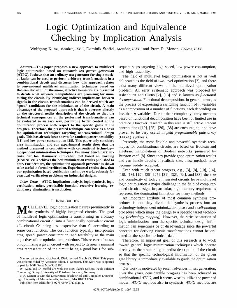
A basic technique to describe many manipulations ofswitching functions is the well-known Shannon expansion.Let be a Boolean function of variables . TheShannon expansion for with respect to is given by
(1)
Shannon’s expansion can be understood as a special case ofan orthonormal expansion [6]
where the functions represent an or-thonormal basis, i.e.,
i) ;
ii)
The functions are calledthe (generalized) cofactorswith respect to the functions .Shannon’s expansion is the special case of the above expansionwhere
and
and is some variable of . Next, we consider anotherspecial case of the above orthonormal expansion where, moregenerally than in Shannon’s expansion, we choose
and
where is some arbitrary Boolean function. This means we obtain an expansion given
by the following equation:
short notation:(2)
The terms and denote the cofactorsof this expansion. In the special case of Shannon’s expansion,the cofactors are chosen by restricting the original functionwith respect to a particular variable, as in (1). We obtain thecofactor for with respect to a variable by setting inthe expression for, similarly, the cofactor for results whensetting . Note that there is no such simple rule in themore general case of (2).
Let the cofactors be denoted , with .Further, let denote an incompletely specifiedfunction . The cofactors in (2)must be chosen such that the following equation holds:
ifX (don’t care) otherwise.
(3)It is easy to see why (3) is true. Assume that the truth tableof is divided into two parts such that is false for all rowsin the first part and true for all rows in the second part. Ifwe first consider the part of the truth table offor whichis true, we can set to the don’t care value for all rows inwhich is false. This means that the cofactor function mustonly have the same value asin those rows where is notdon’t care. Therefore, any valid cofactor for the expansion of(2) covers(denoted ‘ ’) the incompletely specified function
as given by (3). This first part of the function isdescribed by the expression . In the second
KUNZ et al.: LOGIC OPTIMIZATION AND EQUIVALENCE CHECKING 269
part, we are looking at those rows of the truth table for whichis false and obtain .Equation (2) is the basis of our approach to transforming a
combinational network. In order to relate our approach to theBoolean/algebraic techniques of [8], we can refer to function
asdivisor of . Similarly, can be referredto asquotient, and represents theremainderof the division. Further, note that the combined don’t caresets of the two cofactors in (3) are identical to the don’t careset passed to a minimization algorithm for Boolean division,described in [8]. The main issue in our approach, as well asin [8], is to find appropriate (divisor) functions suchthat the internally created don’t cares as given by (3) provide“degrees of freedom” in the combinational network which canbe exploited to minimize its area.
Obviously, the result of such an orthonormal expansion(or Boolean division) depends on how the don’t cares areused in order to minimize the circuit. (Boolean division isnot unique.) In [8], the don’t cares are explicitly passedto an optimization run by ESPRESSO. The approach tobe described here, proceeds in a different way and usesa test generatorto determine the cofactors in the aboveexpansion. As already observed by Brand in [4], circuitrytends to have an increased number of untestable single stuck-at faults if it is not properly optimized with respect to agiven don’t care set. This suggests that the don’t cares createdby the expansion of (2) can also cause untestable stuck-atfaults which can be removed by the standard procedure ofredundancy elimination. In fact, redundancy elimination is asimple way to minimize the circuit with respect to don’t careconditions. Note that redundancy elimination does not requireany explicit knowledge about the don’t care sets. Throughoutthis paper, transformations are examined that createinternaldon’t cares. However, these don’t care conditions are notexplicitly calculated or represented. They are only consideredin our theoretical analysis to illuminate where the redundantfaults to be eliminated come from.
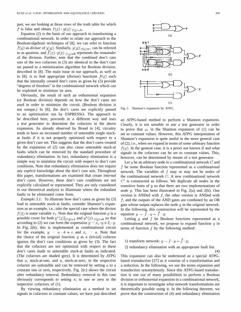
Example 3.1:To illustrate how don’t cares as given by (3)lead to untestable stuck-at faults, consider Shannon’s expan-sion as an example, i.e., take the special case where the divisor
is some variable . Note that the original function is apossible cover for both and so thataccording to (2) we can form the expression .In Fig. 2(b), this is implemented as combinational circuitfor the example, and . Note thatthe choice of the original function as a (trivial) cofactorignores the don’t care conditions as given by (3). The factthat the cofactors are not optimized with respect to thesedon’t cares leads to untestable stuck-at faults as indicated.(The cofactors are shaded grey). It is determined byATPGthat , stuck-at-one, and , stuck-at-zero, in the respectivecofactor are untestable and can be removed by settingto aconstant one or zero, respectively. Fig. 2(c) shows the circuitafter redundancy removal. Redundancy removal in this caseobviously corresponds to setting to one or zero in therespective cofactors of (1).
By viewing redundancy elimination as a method to setsignals in cofactors to constant values, we have just described
(a)
(b)
(c)
Fig. 2. Shannon’s expansion by ATPG.
an ATPG-based method to perform a Shannon expansion.Clearly, it is not sensible to use a test generator in orderto prove that in the Shannon expansion of (1) can beset to constant values. However, thisATPG interpretation ofShannon’s expansion is quite useful in the more general caseof (2), i.e., when we expand in terms of some arbitrary function
. In the general case, it is a priorinot known if and whatsignals in the cofactors can be set to constant values. This,however, can be determined by means of a test generator.
Let be an arbitrary node in a combinational networkandbe some Boolean function represented as a combinational
network. The variables of may or may not be nodes ofthe combinational network . A new combinational network
is constructed as follows. We duplicate all nodes in thetransitive fanin of so that there are two implementations ofnode . This has been illustrated in Fig. 2(a) and 2(b). Oneversion is ANDed with , the other version is ANDed with
, and the outputs of the AND gates are combined by an ORgate whose output replaces the nodein the original network.In the following, this construction will be represented by theequation .
Letting and be Boolean functions represented as acombinational network, we propose to expand functioninterms of function by the following method:
1) transform network:
2) redundancy elimination with an appropriate fault list.(4)
This expansion can also be understood as a special ATPG-basedtransduction[27] as it consists of a transformation anda reduction. In the following, we use the terms expansion andtransduction synonymously. Since this ATPG-based transduc-tion is one out of many possibilities to perform a Booleandivision or orthonormal expansion in a combinational network,it is important to investigate what network transformations aretheoretically possible using it. In the following theorem, weprove that the construction of (4) and redundancy elimination
270 IEEE TRANSACTIONS ON COMPUTER-AIDED DESIGN OF INTEGRATED CIRCUITS AND SYSTEMS, VOL. 16, NO. 3, MARCH 1997
are sufficient for performing arbitrary Boolean transformationsin a network.
Theorem 3.1:Let be a node of a combinational network. The gates in the combinational network can have no
more than two inputs. Further, let be a divisor which isrepresented as a combinational network and realizes a Booleanfunction of no more than twovariables which may or may notbe nodes in such that
1) The transformation of node into given by
followed by2) Redundancy removal (with an appropriate fault list)
generates a combinational network .
For an arbitrary pair of equivalent combinational networksand there exists a sequence of combinational networks
such that and .Proof: Switching algebra is isomorphic to two-valued
Boolean algebra. A Boolean algebra can be defined by Hunt-ington’s axioms. First, we show that all operations (transfor-mations) defined by the axioms can equally be performedby the above manipulations in a combinational network.For each axiom, it has to be shown that the correspondingtransformation can be performed in both directions.
1) Idempotent laws:for :
Equation (4) redundancyelimination: redundancy elimination:
Equation (4) redundancyelimination: redundancy elimination:
for : analogous2) Commutative laws:fulfilled by construction (definition) of primitive gates AND,OR.3) Associative laws:
for :
Equation (4)redundancy elimination: redundancyelimination: (because of commutative laws) ;in opposite direction analogousfor : analogous.4) Absorption:for:
Equation (4)redundancy elimination: redundancyelimination:
Equation (4) redundancyeliminationfor: analogous
5) Distributive laws:
for:
Equation (4)redundancy elimination: redundancyelimination:
Equation (4)redundancy elimination: redundancyelimination:for: analogous6) Universal bounds:for :
Equation (4) redundancyelimination:
Equation (4) redundancy eliminationfor stuck-at-one fault at in second summand:
redundancy elimination for stuck-at-one at signal withconstant one:7) Unary operation:for:
Equation (4) redundancyelimination: redundancy elimination: 1
Equation (4) redundancyelimination:
In order to complete the proof, it must be shown that theabove expansion also allows arbitrary sharing of logic. Thisfollows easily from the following construction. Let be theoriginal network and be the target network. Further, let
denote a network that has tree structure and results fromif all sharing of logic is removed by duplication. Similarly,
let denote the tree version of the target network. Considerthe following construction. First we remove all sharing of logicbetween the different output cones of the original networkso that we obtain . It is easy to derive by the aboveexpansion. Let be some internal fanout branch and assumeits stem is the output of an AND gate with input signalsand . By choosing a divisor and by performing theabove expansion with an appropriate fault list, the AND gateis duplicated, and the fanout point is moved to the inputs of theAND gate. For other gate types, the procedure is analogous.This process is repeated until no more internal fanout pointsexist and has been obtained. After all sharing of logic hasbeen removed, each output cone is isomorphic to a Booleanexpression that can be manipulated arbitrarily as shown usingthe above axioms. Therefore, it is also possible to obtain thenetwork by the above expansion. The target network
results if the duplicated logic is removed. This can beaccomplished if equivalent nodes are substituted. If nodeis to be substituted by node, this can be accomplished byselecting and performing the above expansion. Thisprocess can be repeated for well-selected nodes in untilnetwork is reached.
KUNZ et al.: LOGIC OPTIMIZATION AND EQUIVALENCE CHECKING 271
Fig. 3. Indirect implication and optimization.
Suppose is the given combinational network and isthe combinational network which is optimal with respect tothe given cost function. Theorem 3.1 states that there alwaysexists a sequence of the specified expansion operations suchthat the optimal combinational network is obtained. However,it does not say which divisors shall be used when applying(4). As stated in the theorem, if the network has gates with nomore than two inputs, it is sufficient to only consider divisorscreated as function of two nodes in the network. This reducesthe number of divisors that (theoretically) have to be examined.Of course, this restriction does not imply that more complexdivisors are of no use in the presented expansion scheme. Ifmore complex divisors are used, the network is transformed inbigger steps. Theorem 3.1 does not put any restriction on thechoice of divisors to transform the network. Further degrees offreedom for the expansions lie within redundancy elimination.The result of redundancy elimination depends on what faultsare targeted and in which order they are processed.
Theorem 3.1 represents the theoretical basis of ageneralATPG-basedframework to logic optimization. As mentioned,redundancy elimination and the transformation of (4)per sedo not represent an optimization technique. However, theyprovide the basic tool kit to modify a combinational network.In order to obtain good optimization results, efficient heuristicshave to be developed to decide what divisors to choose andhow to set up the fault list for redundancy elimination. Thiswill be described in the following.
IV. I DENTIFYING DIVISORS BY IMPLICATIONS
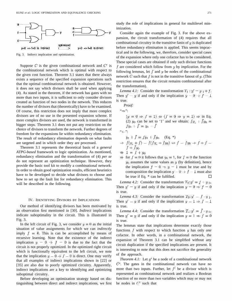
Our method of identifying divisors has been motivated byan observation first mentioned in [30].Indirect implicationsindicate suboptimality in the circuit. This is illustrated inFig. 3.
In the left circuit of Fig. 3, we consider as the initialsituation of value assignments for which we canindirectlyimply . This is can be accomplished by means ofrecursive learning. Note that the existence of the indirectimplication is due to the fact that thecircuit is not properly optimized. In the optimized right circuitwhich is functionally equivalent to the left circuit, we notethat the implication is direct. One may verifythat all examples of indirect implications shown in [22] or[35] are also due to poorly optimized circuitry. Apparently,indirect implications are a key to identifying and optimizingsuboptimal circuitry.
Before developing an optimization strategy based on dis-tinguishing between direct and indirect implications, we first
study the role of implications in general for multilevel min-imization.
Consider again the example of Fig. 3. For the above ex-pansion, the circuit transformation of (4) requires that allcombinational circuitry in the transitive fanin ofis duplicatedbefore redundancy elimination is applied. This seems imprac-tical and in the following, we, therefore, consider special casesof the expansion where only one cofactor has to be considered.These special cases are obtained if only such divisor functions
are considered which follow from by implication. For thefollowing lemmas, let and be nodes of the combinationalnetwork such that is not in the transitive fanout of. (Thisrestriction ensures that the circuit remains combinational afterthe transformation).
Lemma 4.1:Consider the transformation .Then if and only if the implicationis true.
Proof:
“ ”:
in Eq.(2) can be set to ‘1’ and we obtain:
“ ”:
(Eq. *)
for it follows that , for the functionassumes the same values as(by definition), hence
the implication must be true and bycontraposition the implication must alsobe true if Eq. * can be fulfilled.
Lemma 4.2:Consider the transformation .Then if and only if the implicationis true.
Lemma 4.3:Consider the transformation .Then if and only if the implicationis true.
Lemma 4.4:Consider the transformation .Then if and only if the implicationis true.The lemmas state that implications determine exactly thosefunctions with respect to which function has only onecofactor. In other words, in a combinational network, theexpansion of Theorem 3.1 can be simplified without anycircuit duplication if the specified implications are present. Itis interesting to note that this does not sacrifice the generalityof the approach.
Theorem 4.1:Let be a node of a combinational network. The gates in the combinational network can have no
more than two inputs. Further, let be a divisor which isrepresented as combinational network and realizes a Booleanfunction of no more than two variables which may or may notbe nodes in such that
272 IEEE TRANSACTIONS ON COMPUTER-AIDED DESIGN OF INTEGRATED CIRCUITS AND SYSTEMS, VOL. 16, NO. 3, MARCH 1997
1) The transformation of node into given by
forforforfor
followed by2) Redundancy removal (with appropriate fault list) gen-
erates a combinational network . For an arbi-trary pair of equivalent combinational networks and
, there exists a sequence of combinational networkssuch that and .
Proof: Follows from the proof of Theorem 3.1, by notingthat all functions and divisors used satisfy one of theimplications specified above.
Note that Lemmas 4.1–4.4 only cover those cases wherea node in a combinational network can be replaced bysome equivalent function . A function at node can alsobe replaced by some nonequivalent functionif this does notchange the function of the combinationalnetwork as a whole. Such functions are calledpermissiblefunctions [27]. By considering permissible functions ratherthan only equivalent functions as candidates for substitutionat each node, we exploit additional degrees of freedom asgiven by observability don’t cares[8]. Permissible functionscan also be obtained by recursive learning:
Definition 4.1: For an arbitrary node in a combinationalnetwork , assume the single fault stuck-at- .If is a value assignment at a nodewhichis necessaryto detect the fault at at least one primary outputof , then follows from by “ -implication”and is denoted .
The conventional implications are a special case of such-implications. Replacing the implications in Lemmas 4.1–4.4by -implications, we obtain the following generalization.
Theorem 4.2:Let and be arbitrary nodes in a combi-national network where is not in the transitive fanout of
and both stuck-at faults at nodeare testable.The function with is apermissible functionat node if and only if the -implication
is true.Proof: “ ”:
If is true, then is true. Wepartition the set of possible combinations of input assignments(rows in the truth table) into two disjoint subsets, where eachfulfills one of the following conditions:
Case 1: ( and ) or :For these inputs, is true and Lemma 4.1applies, for these inputs and always assume the samevalue.Case 2: and :For these inputs, can have a different value than. With
the function can only assume the faulty value ‘1.’However, this cannot lead to a wrong value at the primaryoutputs of because the fault stuck-at-one at nodecannot
be tested since and .
“ ”: The transformation is permissible if one of the fol-lowing cases is fulfilled:
Case 1: and are equivalentLemma 4.1 applies, if is true then
is true.Case 2: and and stuck-at-zero is untestableunder this condition
, i.e., this case cannot occur.Case 3: and and stuck-at-one is untestableunder this condition.With and can only occur if
is true. The term in the above transformationmeans that this node can be implemented as an arbitraryfunction assuming the same values asfor . As aspecial case, assume that . In this special case, if
then is sufficient to produce a “faulty” signal‘1’ at node . Now consider the set of all test vectors forstuck-at-one in the original circuit that produce . Everysuch test will result in a faulty response of the transformedcircuit. Therefore, the transformation is only allowed if sucha test does not exist. However, if a test forstuck-at-oneexists in general, it is required that there is none whichproduces . This means that is necessary for
fault detection and must be true. If thiscondition is necessary for the special case that , it isalso necessary for the general statement sinceis one ofthe possible choices to implement.
Theorem 4.3:Analogous to Lemma 4.2.Theorem 4.4:Analogous to Lemma 4.3.Theorem 4.5:Analogous to Lemma 4.4.Theorems 4.2–4.5 represent the basis for the circuit trans-
formations in our optimization method. As the transformationsgiven in Theorems 4.2–4.5 represent special simplified casesof (2), they also provide simplified cases of (4). As will beillustrated in Section V, the constructions based on (4) and theabove theorems provide good candidates for the expansion ofTheorem 3.1.
Recursive learning can be used to determine all valueassignments necessary to detect a single stuck-at fault,i.e., it is a technique to perform all -implications. Thisis accomplished by two routinesmake_all_implications(),and fault_propagation_learning()as given in [22] if theyare performed for the five-valued logic alphabet
of Roth [33]. Therefore, by recursive learningit is possible to derive all cases where Theorems 4.2–4.5 apply.
The number of implications and -implications can bevery large so that it is impossible to examine all trans-formations. At this point, however, we come back to theobservation discussed earlier. Implications which can onlybe derived by “great effort” represent the promising candi-dates for the transformations as given in Theorems 4.2–4.5.These indirect implications are only a small fraction of allpossible implications. In the following, we refer to a-
implication as indirectif it can neither be derived by direct implication nor byunique sensitization[17] at the dominators [21] of . Inother words, all those necessary assignments obtained by the
KUNZ et al.: LOGIC OPTIMIZATION AND EQUIVALENCE CHECKING 273
learning case of routinesfault_propagation-_learning()andmake_all_implications()are implied indirectly and providethe set of promising candidates for the circuit transforma-tions.
As it turns out, the concept of relating the complexity ofthe implication problem to minimality of the combinationalnetwork permits a new and promising approach to guidinglogic minimization techniques.
V. OPTIMIZATION PROCEDURE
The described concepts have been implemented as part ofthe HANNover Implication Tool Based on Learning (HAN-NIBAL) tool system. Table I summarizes the general programflow for circuit optimization. HANNIBAL performs logicoptimization by applying the described concepts stepwise toall nodes in the combinational network. The optimizationprocedure moves from node to node in the combinationalnetwork. Experiments showed that the optimization resultsare only moderately sensitive to the order in which thedifferent circuit nodes are processed. However, best resultswere generally obtained by processing the nodes accordingto their topological level moving from the primary inputstoward the primary outputs. For a selected node, recursivelearning is used to derive promising divisor functions. Thecandidates found promising are stored in lists and tried insequence. When identifying implications, it is important thatwe run recursive learning only for one node at a time andthen transform the given node by the implications obtained.Therefore, after modifying the circuit, we have to update thedata only for the current node.
For each candidate implication, the circuit is transformedaccording to the rules given in Section IV. After each trans-formation, redundancy elimination is employed. To make thisprocess as fast as possible, the deterministic test set is alwaysmaintained for the most recent version of the circuit. Aftereach circuit transformation, this test set is simulated to quicklydiscard many faults from further consideration so that a onlyfew faults have to be targeted explicitly by deterministicATPG. After redundancy elimination has been completed, itis checked whether the circuit became smaller or not. If itbecame smaller, the current circuit is maintained, otherwise theprevious version is recovered. This is continued for all nodesin the network until no more improvements can be found. InHANNIBAL, several runs are made through the circuit varyingthe recursion depth and the number of candidate implicantsbeing tried at each node in different runs.
For each step of redundancy removal, we determine thefault list as follows:
1) include in the fault list both stuck-at faults at all signalsthat were “touched” by recursive learning when derivingthe current divisor;
2) exclude from the fault list, all faults in the circuitryadded for the current transformation.
Limiting the fault list to signals being processed by the event-driven recursive learning routine proved to be a very goodheuristic to speed up fault simulation and ATPG (up to a factorof 4) without significantly sacrificing optimization quality.
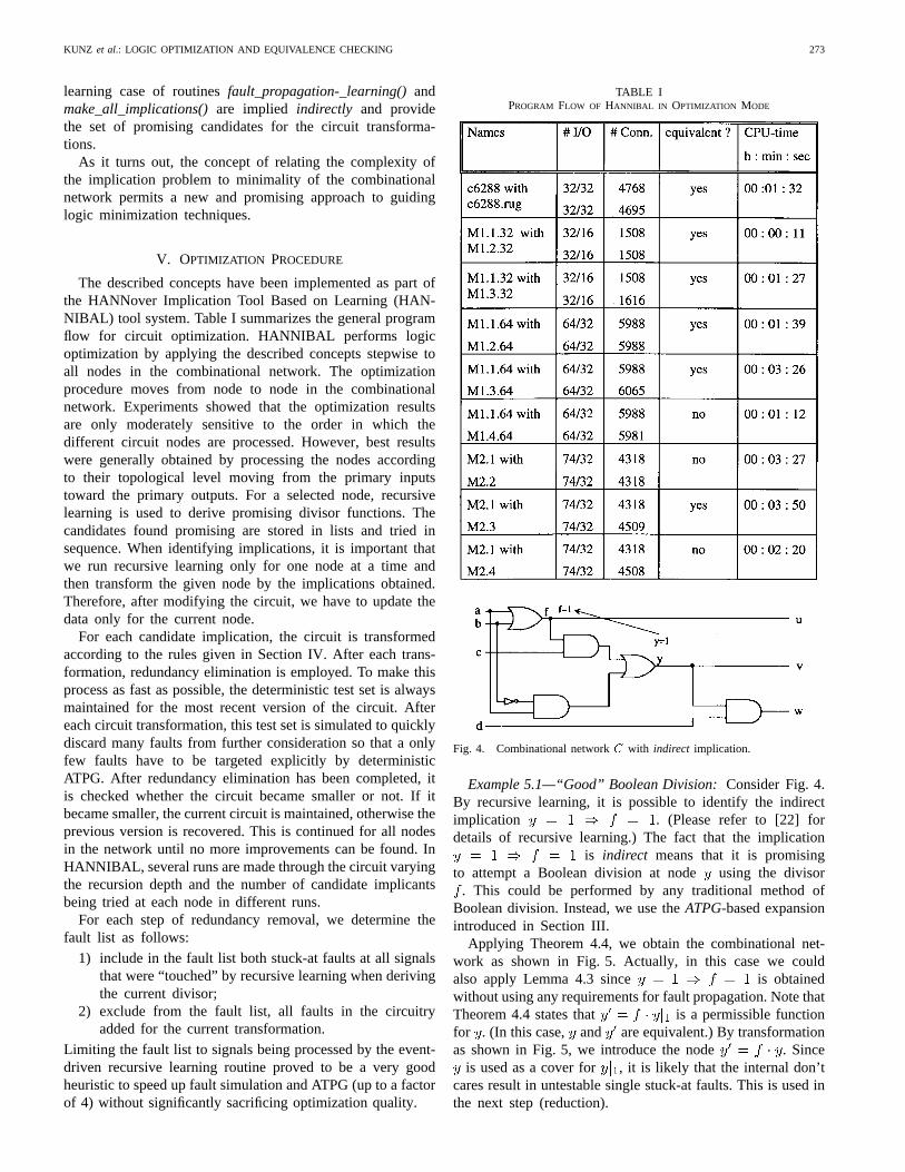
TABLE IPROGRAM FLOW OF HANNIBAL IN OPTIMIZATION MODE
Fig. 4. Combinational networkC with indirect implication.
Example 5.1—“Good” Boolean Division:Consider Fig. 4.By recursive learning, it is possible to identify the indirectimplication . (Please refer to [22] fordetails of recursive learning.) The fact that the implication
is indirect means that it is promisingto attempt a Boolean division at node using the divisor
. This could be performed by any traditional method ofBoolean division. Instead, we use theATPG-based expansionintroduced in Section III.
Applying Theorem 4.4, we obtain the combinational net-work as shown in Fig. 5. Actually, in this case we couldalso apply Lemma 4.3 since is obtainedwithout using any requirements for fault propagation. Note thatTheorem 4.4 states that is a permissible functionfor . (In this case, and are equivalent.) By transformationas shown in Fig. 5, we introduce the node . Since
is used as a cover for , it is likely that the internal don’tcares result in untestable single stuck-at faults. This is used inthe next step (reduction).
274 IEEE TRANSACTIONS ON COMPUTER-AIDED DESIGN OF INTEGRATED CIRCUITS AND SYSTEMS, VOL. 16, NO. 3, MARCH 1997
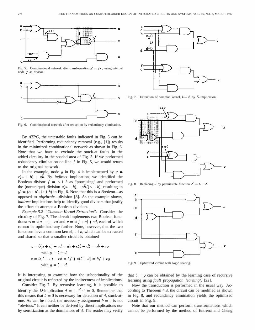
Fig. 5. Combinational network after transformationy0= f �y using internal
node f as divisor.
Fig. 6. Combinational network after reduction by redundancy elimination.
By ATPG, the untestable faults indicated in Fig. 5 can beidentified. Performing redundancy removal (e.g., [1]) resultsin the minimized combinational network as shown in Fig. 6.Note that we have to exclude the stuck-at faults in theadded circuitry in the shaded area of Fig. 5. If we performedredundancy elimination on line in Fig. 5, we would returnto the original network.
In the example, node in Fig. 4 is implemented by. By indirect implication, we identified the
Boolean divisor as “promising” and performedthe (nonunique) division , resulting in
in Fig. 6. Note that this is aBoolean—asopposed toalgebraic—division [8]. As the example shows,indirect implications help to identify good divisors that justifythe effort to attempt a Boolean division.
Example 5.2–“Common Kernel Extraction”:Consider thecircuitry of Fig. 7. The circuit implements two Boolean func-tions: and , each of whichcannot be optimized any further. Note, however, that the twofunctions have a common kernel, , which can be extractedand shared so that a smaller circuit is obtained
with
with
It is interesting to examine how the suboptimality of theoriginal circuit is reflected by the indirectness of implications.
Consider Fig. 7. By recursive learning, it is possible toidentify the -implication . Remember thatthis means that is necessary for detection of, stuck-at-one. As can be noted, the necessary assignment is not“obvious.” It can neither be derived by direct implications norby sensitization at the dominators of. The reader may verify
Fig. 7. Extraction of common kernel,b+ d, by D-implication.
Fig. 8. Replacingd by permissible functiond0 = b + d.
Fig. 9. Optimized circuit with logic sharing.
that can be obtained by the learning case of recursivelearning usingfault_propagation_learning()[22].
Now the transduction is performed in the usual way. Ac-cording to Theorem 4.3, the circuit can be modified as shownin Fig. 8, and redundancy elimination yields the optimizedcircuit in Fig. 9.
Note that our method can perform transformations whichcannot be performed by the method of Entrena and Cheng
KUNZ et al.: LOGIC OPTIMIZATION AND EQUIVALENCE CHECKING 275
[16] and the method of [10]. To the best of our understanding,in the above example, the minimization cannot be obtainedby only adding and removing connections as in [10] and[16]. This is because the methods of [10], [16] require theexistence of gates of a certain type at the location wherethe added connection (gate) is anchored. Based on the ex-pansion described in Section III, our approach uses a widerspectrum of circuit transformation. This could possibly imposehigher computational costs, however, our results show that theheuristic strategy of only using indirect implications for circuittransformation can effectively limit the search space.
As presented in [22], recursive learning consistsof two techniques, make_all_implications() andfault_propagation_learning(). It is interesting to notethat implications obtained bymake_all_implications()resultin transductions that, in conventional terms, often leadto transformations that are most adequately describedby Boolean division or Boolean resubstitution. This wasillustrated in Example 5.1. If the implication is obtainedby fault_propagation_learning()as in Example 5.2, theexpansion often performs what is commonly referred to ascommon kernel extraction.
Limitations: 1) The examples also show the limitation ofour method. By implication analysis we only consider divisorsthat are already present as nodes in the network. Therefore, wedo not completely utilize the generality of our basic approachas given by Theorem 4.1. Extensions are under way to deriveimplicants and D-implicants [36] for a given node in thenetwork which are not explicitly present as nodes in thenetwork. AND/OR graphs, using which such implications canbe derived, have been introduced in [36].
2) Our techniques operate on a gate-level netlist descrip-tion. As mentioned, this is of advantage if specific technicalinformation shall be considered in the optimization process.However, it has not yet been considered how the presentedtechniques can handle circuits withcomplex gatesin anefficient way. Our tool, HANNIBAL, at this point, is limited tohandling only the basic gate types, AND, OR, NAND, NOR,INV, XOR. Future work will therefore extend our techniquesto handling complex gates so that arbitrary libraries can beprocessed.
VI. A PPLICATION TO LOGIC VERIFICATION
The described minimization approach can also be appliedto logic verification. Formal logic verification of integratedcircuits has become of great interest for many industrialdesigners and manufacturers of highly integrated circuits. Es-pecially, in safety-critical applications, it is of great importanceto verify that the implemented logic circuit is equivalentto its specification. When verifying digital circuits, an im-portant subproblem is to check whether two combinationalcircuits are functionally equivalent. Traditionally, this problemis approached by generating a canonical (unique) formof the circuits to be verified. The circuits are equivalent iftheir canonical forms are isomorphic. Unfortunately, canonicalforms of Boolean functions may grow extremely large evenfor relatively small designs. The most compact canonical forms
known to date areReduced Ordered Binary Decision Diagrams(ROBDD’s) [9] and related graph representations of Booleanfunctions. Therefore, binary decision diagrams (BDD’s) havebecome very popular for solving logic verification problems.Some classes of circuits, however, are not amenable to a BDDanalysis, since the size of the BDD’s grows exponentially withthe size of the circuit.
More recently, to overcome the limitations of BDD-basedapproaches, a different approach to logic verification has beenproposed in [5], [23] which exploits the structural “similarity”between the designs. Instead of producing canonical formsthese techniques extract the similarity between designs byATPG and implications between signals in the two circuits.These techniques have only little memory requirements andproved successful in verifying circuits that cannot be verifiedby BDD-based approaches. Further developments based onthese techniques have been proposed in [15], [20], [29],and [37]. Note, however, that such techniques may requireexcessive amounts of central processing unit (CPU)-time ifthe circuits have little structural similarity. Therefore, it is animportant problem to study how to exploit the “similarity”between designs as efficiently as possible. In this section, wepropose to use the presented optimization procedure for thispurpose. There is a wealth of powerful synthesis methods,and it should be noted that many of these methods can alsobe useful in logic verification.
A. Logic Verification by Optimization
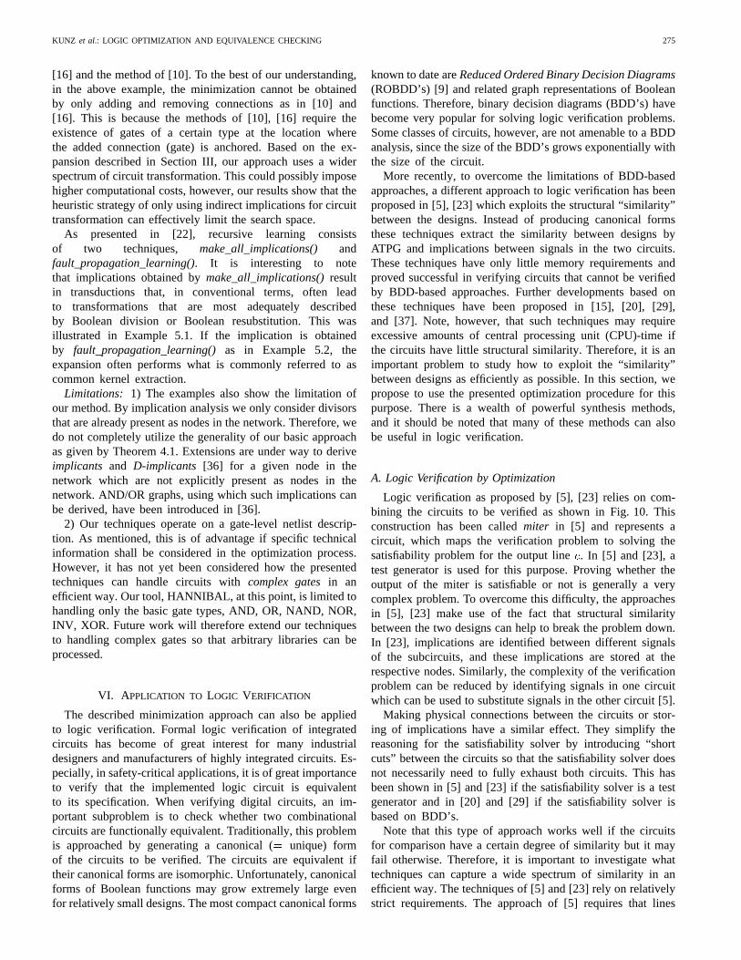
Logic verification as proposed by [5], [23] relies on com-bining the circuits to be verified as shown in Fig. 10. Thisconstruction has been calledmiter in [5] and represents acircuit, which maps the verification problem to solving thesatisfiability problem for the output line. In [5] and [23], atest generator is used for this purpose. Proving whether theoutput of the miter is satisfiable or not is generally a verycomplex problem. To overcome this difficulty, the approachesin [5], [23] make use of the fact that structural similaritybetween the two designs can help to break the problem down.In [23], implications are identified between different signalsof the subcircuits, and these implications are stored at therespective nodes. Similarly, the complexity of the verificationproblem can be reduced by identifying signals in one circuitwhich can be used to substitute signals in the other circuit [5].
Making physical connections between the circuits or stor-ing of implications have a similar effect. They simplify thereasoning for the satisfiability solver by introducing “shortcuts” between the circuits so that the satisfiability solver doesnot necessarily need to fully exhaust both circuits. This hasbeen shown in [5] and [23] if the satisfiability solver is a testgenerator and in [20] and [29] if the satisfiability solver isbased on BDD’s.
Note that this type of approach works well if the circuitsfor comparison have a certain degree of similarity but it mayfail otherwise. Therefore, it is important to investigate whattechniques can capture a wide spectrum of similarity in anefficient way. The techniques of [5] and [23] rely on relativelystrict requirements. The approach of [5] requires that lines
276 IEEE TRANSACTIONS ON COMPUTER-AIDED DESIGN OF INTEGRATED CIRCUITS AND SYSTEMS, VOL. 16, NO. 3, MARCH 1997
Fig. 10. Exploiting structural similarity in a miter.
in one circuit can be replaced by lines in the other circuitexploiting observability don’t cares. In [20] or [23], it isrequired that there exist logic implications, e.g., incircuit implies in circuit . This can be a looserrequirement than demanding a substitution, but on the otherhand, [20] and [23] do not exploit observability don’t cares.
Taking all of this into account suggests that the verificationproblem should be simplified effectively by performing logicaltransformations in the miter so that logic common to thetwo designs can be extracted and shared. If the circuitsare equivalent, then one circuit must eventually be mergedinto the other circuit. As a special case, the substitutions of[5] perform such an operation. More generally, any knownsynthesis technique can be used to accomplish this task. Thegeneral goal is tooptimizethe miter. If the miter is reduced toa constant zero, the two circuits are proved equivalent. If thisis not (or only partially) possible, then it must be attempted togenerate a distinguishing vector using ATPG.
If the circuits have a fair amount of structuralsimilarity,this means that the miter can be optimized by a sequenceof fairly local circuit transformations. If the circuits becomeless similar, then deriving these transformations becomes moreand more complex, and it becomes important to fully exploitthe range and power of modern synthesis techniques. Theadvantage of formulating verification as amiter optimizationproblem is that the power of modern synthesis techniquesbecomes available to the difficult problem of logic verification.
As experimentally confirmed in Section VII, circuit trans-formations derived by indirect implications cover a largespectrum of the circuit manipulations performed in stan-dard synthesis procedures like [8]. Further, since implicationspermit an easy and effective guidance of the optimizationprocess, we base our verification procedure on the optimizationprocedure of Section V.
B. Heuristic Guidance in a Miter
Optimization in a miter has special characteristics whichare discussed in this section with respect to the optimizationprocedure of Section V.
Selecting Implications:Using our approach, it must be at-tempted to identify implications that are valid between twonodes that belong todifferent subcircuits of the miter. If thecorresponding transformations are performed, this introducesa sharing of logic between the circuits. Enforcing a sharingof logic between the circuits has two beneficial effects. Itgenerally reduces the size of the miter, and it tends to increasethe degree of similarity in the remaining, unshared parts ofthe circuits if the original circuits are equivalent. If the twonetworks are forced to share the same subfunctions, this leavesless “freedom” for the implementation of the remaining parts.This is illustrated in the following example.
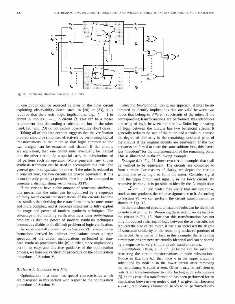
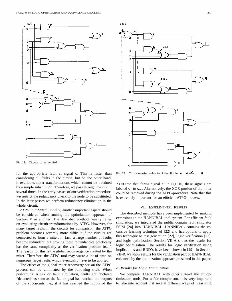
Example 6.1: Fig. 11 shows two circuit examples that shallbe verified to be equivalent. The circuits are combined toform a miter. For reasons of clarity, we depict the circuitswithout the extra logic to form the miter. Consider signal
in the upper circuit and signal in the lower circuit. Byrecursive learning, it is possible to identify the-implication
. The reader may verify that any test for,stuck-at-one produces the value assignment . Accordingto Section VI, we can perform the circuit transformation asshown in Fig. 12.
In the transformed circuit, untestable faults can be identifiedas indicated in Fig. 12. Removing these redundancies leads tothe circuit in Fig. 13. Note that this transformation has notonly introduced a sharing of logic between the two circuits andreduced the size of the miter, it has also increased the degreeof structural similarity in the remaining unshared portions ofthe circuit. As a matter of fact, in this example, the remainingcircuit portions are now structurally identical and can be sharedby a sequence of very simple circuit transformations.
Substitution: Often, a lot of CPU-time can be saved byrestricting the circuit transformations to node substitutions.Notice in Example 6.1 that node in the upper circuit issubstituted by node in the lower circuit after removingthe redundancy , stuck-at-zero. Often it may be sufficient torestrict all transformations to only finding such substitutions[5]. In this case, if a transformation has been performed for animplication between two nodesand as given in Theorems4.2–4.5, redundancy elimination needs to be performed only
KUNZ et al.: LOGIC OPTIMIZATION AND EQUIVALENCE CHECKING 277
Fig. 11. Circuits to be verified.
for the appropriate fault at signal. This is faster thanconsidering all faults in the circuit, but on the other hand,it overlooks miter transformations which cannot be obtainedby a simple substitution. Therefore, we pass through the circuitseveral times. In the early passes of our verification procedure,we restrict the redundancy check to the node to be substituted.In the later passes we perform redundancy elimination in thewhole circuit.
ATPG in a Miter: Finally, another important aspect shouldbe considered when running the optimization approach ofSection V in a miter. The described method heavily relieson evaluating circuit transformations by ATPG. However, formany target faults in the circuits for comparison, the ATPGproblem becomes severely more difficult if the circuits areconnected to form a miter. In fact, a large number of faultsbecome redundant, but proving these redundancies practicallyhas the same complexity as the verification problem itself.The reason for this is the global reconvergence created by themiter. Therefore, the ATPG tool may waste a lot of time onnumerous target faults which eventually have to be aborted.
The effect of the global miter reconvergence on the ATPGprocess can be eliminated by the following trick. Whenperforming ATPG or fault simulation, faults are declared“detected” as soon as the fault signal has reached the outputsof the subcircuits, i.e., if it has reached the inputs of the
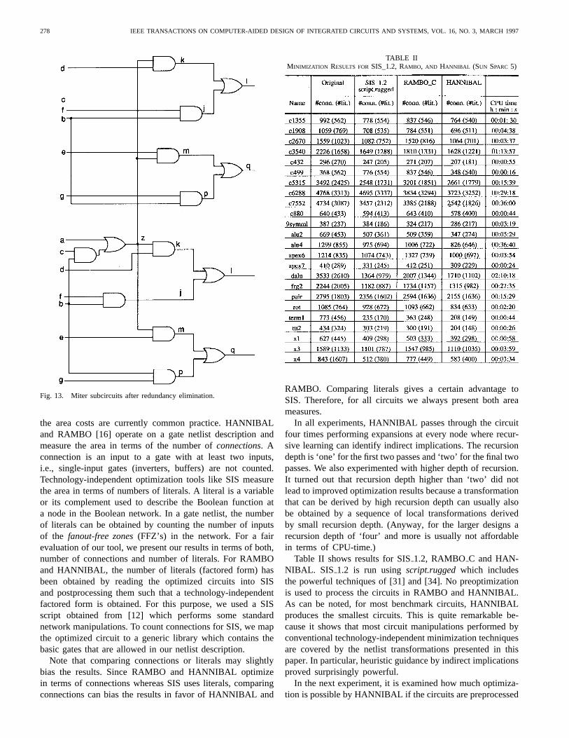
Fig. 12. Circuit transformation forD-implication a = 0D�! z = 0.
XOR-tree that forms signal . In Fig. 10, these signals arelabeled to . Alternatively, the XOR-portion of the mitercould be removed during the ATPG-procedure. Note that thisis extremely important for an efficient ATPG-process.
VII. EXPERIMENTAL RESULTS
The described methods have been implemented by makingextensions to the HANNIBAL tool system. For efficient faultsimulation, we integrated the public domain fault simulatorFSIM [24] into HANNIBAL. HANNIBAL contains the re-cursive learning technique of [22] and has options to applythis technique to test generation [22], logic verification [23],and logic optimization. Section VII-A shows the results forlogic optimization. The results for logic verification usingimplications and BDD’s have been shown in [29]. In SectionVII-B, we show results for the verification part of HANNIBALenhanced by the optimization approach presented in this paper.
A. Results for Logic Minimization
We compare HANNIBAL with other state-of the art op-timization tools. For a fair comparison, it is very importantto take into account that several different ways of measuring
278 IEEE TRANSACTIONS ON COMPUTER-AIDED DESIGN OF INTEGRATED CIRCUITS AND SYSTEMS, VOL. 16, NO. 3, MARCH 1997
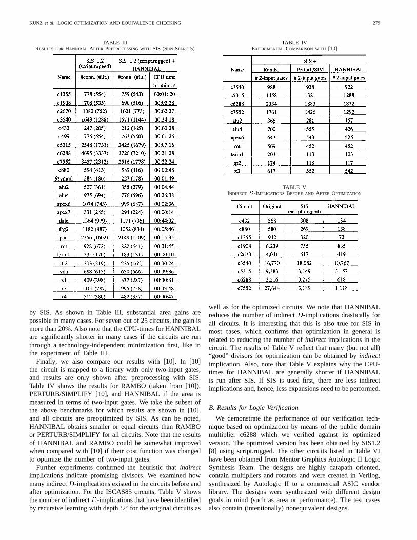
Fig. 13. Miter subcircuits after redundancy elimination.
the area costs are currently common practice. HANNIBALand RAMBO [16] operate on a gate netlist description andmeasure the area in terms of the number ofconnections. Aconnection is an input to a gate with at least two inputs,i.e., single-input gates (inverters, buffers) are not counted.Technology-independent optimization tools like SIS measurethe area in terms of numbers of literals. A literal is a variableor its complement used to describe the Boolean function ata node in the Boolean network. In a gate netlist, the numberof literals can be obtained by counting the number of inputsof the fanout-free zones(FFZ’s) in the network. For a fairevaluation of our tool, we present our results in terms of both,number of connections and number of literals. For RAMBOand HANNIBAL, the number of literals (factored form) hasbeen obtained by reading the optimized circuits into SISand postprocessing them such that a technology-independentfactored form is obtained. For this purpose, we used a SISscript obtained from [12] which performs some standardnetwork manipulations. To count connections for SIS, we mapthe optimized circuit to a generic library which contains thebasic gates that are allowed in our netlist description.
Note that comparing connections or literals may slightlybias the results. Since RAMBO and HANNIBAL optimizein terms of connections whereas SIS uses literals, comparingconnections can bias the results in favor of HANNIBAL and
TABLE IIMINIMIZATION RESULTS FORSIS_1.2, RAMBO, AND HANNIBAL (SUN SPARC 5)
RAMBO. Comparing literals gives a certain advantage toSIS. Therefore, for all circuits we always present both areameasures.
In all experiments, HANNIBAL passes through the circuitfour times performing expansions at every node where recur-sive learning can identify indirect implications. The recursiondepth is ‘one’ for the first two passes and ‘two’ for the final twopasses. We also experimented with higher depth of recursion.It turned out that recursion depth higher than ‘two’ did notlead to improved optimization results because a transformationthat can be derived by high recursion depth can usually alsobe obtained by a sequence of local transformations derivedby small recursion depth. (Anyway, for the larger designs arecursion depth of ‘four’ and more is usually not affordablein terms of CPU-time.)
Table II shows results for SIS1.2, RAMBO C and HAN-NIBAL. SIS 1.2 is run usingscript.ruggedwhich includesthe powerful techniques of [31] and [34]. No preoptimizationis used to process the circuits in RAMBO and HANNIBAL.As can be noted, for most benchmark circuits, HANNIBALproduces the smallest circuits. This is quite remarkable be-cause it shows that most circuit manipulations performed byconventional technology-independent minimization techniquesare covered by the netlist transformations presented in thispaper. In particular, heuristic guidance by indirect implicationsproved surprisingly powerful.
In the next experiment, it is examined how much optimiza-tion is possible by HANNIBAL if the circuits are preprocessed
KUNZ et al.: LOGIC OPTIMIZATION AND EQUIVALENCE CHECKING 279
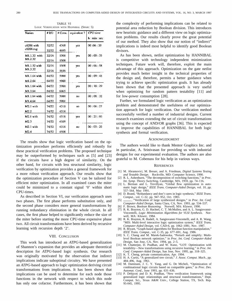
TABLE IIIRESULTS FORHANNIBAL AFTER PREPROCESSING WITHSIS (SUN SPARC 5)
by SIS. As shown in Table III, substantial area gains arepossible in many cases. For seven out of 25 circuits, the gain ismore than 20%. Also note that the CPU-times for HANNIBALare significantly shorter in many cases if the circuits are runthrough a technology-independent minimization first, like inthe experiment of Table III.
Finally, we also compare our results with [10]. In [10]the circuit is mapped to a library with only two-input gates,and results are only shown after preprocessing with SIS.Table IV shows the results for RAMBO (taken from [10]),PERTURB/SIMPLIFY [10], and HANNIBAL if the area ismeasured in terms of two-input gates. We take the subset ofthe above benchmarks for which results are shown in [10],and all circuits are preoptimized by SIS. As can be noted,HANNIBAL obtains smaller or equal circuits than RAMBOor PERTURB/SIMPLIFY for all circuits. Note that the resultsof HANNIBAL and RAMBO could be somewhat improvedwhen compared with [10] if their cost function was changedto optimize the number of two-input gates.
Further experiments confirmed the heuristic thatindirectimplications indicate promising divisors. We examined howmany indirect -implications existed in the circuits before andafter optimization. For the ISCAS85 circuits, Table V showsthe number of indirect -implications that have been identifiedby recursive learning with depth ‘2’ for the original circuits as
TABLE IVEXPERIMENTAL COMPARISON WITH [10]
TABLE VINDIRECT D-IMPLICATIONS BEFORE AND AFTER OPTIMIZATION
well as for the optimized circuits. We note that HANNIBALreduces the number of indirect-implications drastically forall circuits. It is interesting that this is also true for SIS inmost cases, which confirms that optimization in general isrelated to reducing the number ofindirect implications in thecircuit. The results of Table V reflect that many (but not all)“good” divisors for optimization can be obtained byindirectimplication. Also, note that Table V explains why the CPU-times for HANNIBAL are generally shorter if HANNIBALis run after SIS. If SIS is used first, there are less indirectimplications and, hence, less expansions need to be performed.
B. Results for Logic Verification
We demonstrate the performance of our verification tech-nique based on optimization by means of the public domainmultiplier c6288 which we verified against its optimizedversion. The optimized version has been obtained by SIS1.2[8] using script.rugged. The other circuits listed in Table VIhave been obtained from Mentor Graphics Autologic II LogicSynthesis Team. The designs are highly datapath oriented,contain multipliers and rotators and were created in Verilog,synthesized by Autologic II to a commercial ASIC vendorlibrary. The designs were synthesized with different designgoals in mind (such as area or performance). The test casesalso contain (intentionally) nonequivalent designs.
280 IEEE TRANSACTIONS ON COMPUTER-AIDED DESIGN OF INTEGRATED CIRCUITS AND SYSTEMS, VOL. 16, NO. 3, MARCH 1997
TABLE VILOGIC VERIFICATION WITH HANNIBAL (SPARC 5)
The results show that logic verification based on the op-timization procedure performs efficiently and robustly forthese practical verification problems. The proposed techniquemay be outperformed by techniques such as [5] and [23]if the circuits have a high degree of similarity. On theother hand, for circuits with less structural similarity, logicverification by optimization provides a general framework fora more robust verification approach. Our results show thatthe optimization procedure of Section V can be tailored forefficient miter optimization. In all examined cases the mitercould be minimized to a constant signal ‘0’ within shortCPU-times.
As described in Section VI, our verification approach usestwo phases. The first phase performs substitution only, andthe second phase considers more general transformations byrunning redundancy elimination in the whole circuit. In allcases, the first phase helped to significantly reduce the size ofthe miter before starting the more CPU-time expensive phasetwo. All circuit transformations have been derived by recursivelearning with recursion depth ‘2’.
VIII. C ONCLUSION
This work has introduced anATPG-based generalizationof Shannon’s expansion that provides an adequate theoreticaldescription for ATPG-based logic synthesis. Our researchwas originally motivated by the observation that indirectimplications indicate suboptimal circuitry. We have presentedanATPG-based approach to logic optimization deriving circuittransformations from implications. It has been shown thatimplications can be used to determine for each node thosefunctions in the network with respect to which this nodehas only one cofactor. Furthermore, it has been shown that
the complexity of performing implications can be related topotential area reduction by Boolean division. This introducesnew heuristic guidance and a different view on logic optimiza-tion problems. Our results clearly prove the great potentialof our method. They also show that our notion of “indirect”implications is indeed most helpful to identify good Booleandivisors.
As has been shown, netlist optimization by HANNIBALis competitive with technology independent minimizationtechniques. Future work will, therefore, exploit the mainadvantage of this approach. Optimization on the gate netlistprovides much better insight in the technical properties ofthe design and, therefore, permits a better guidance whentrying to achieve specific optimization goals. It has alreadybeen shown that the presented approach is very usefulwhen optimizing for random pattern testability [11] andfor low-power consumption [28].
Further, we formulated logic verification as an optimizationproblem and demonstrated the usefulness of our optimiza-tion approach for logic verification. Our verification methodsuccessfully verified a number of industrial designs. Currentresearch examines extending the set of circuit transformationsusing the concept of AND/OR graphs [36]. This is expectedto improve the capabilities of HANNIBAL for both logicsynthesis and formal verification.
ACKNOWLEDGMENT
The authors would like to thank Mentor Graphics Inc. andin particular, A. Srinivasan for providing us with industrialdesigns for our experimental evaluation. The authors are alsograteful to M. Cobenuss for his help in various ways.
REFERENCES
[1] M. Abramovici, M. Breuer, and A. Friedman,Digital Systems Testingand Testable Design. Rockville, MD: Computer Science, 1990.
[2] R. L. Ashenhurst, “The decomposition of switching functions,” inProc.Int. Symp. Theory Switching, Cambridge, MA, 1959, pp. 74–116.
[3] L. Berman and L. Trevillyan, “Global flow optimization in auto-matic logic design,”IEEE Trans. Computer-Aided Design, vol. 10, pp.557–564, May 1991.
[4] D. Brand, “Redundancy and don’t cares in logic synthesis,”IEEE Trans.Comput., vol. C-32, pp. 947–952, Oct. 1983.
[5] , “Verification of large synthesized designs,” inProc. Int. Conf.Computer-Aided Design, Santa Clara, CA, Nov. 1993, pp. 534–537.
[6] F. Brown, Boolean Reasoning. Norwell, MA: Kluwer, 1990.[7] R. K. Brayton, G. D. Hachtel, C. T. McMullen, and A. L. Sangiovanni-
Vincentelli, Logic Minimization Algorithms for VLSI Synthesis. Nor-well, MA: Kluwer, 1984.
[8] R. K. Brayton, R. Rudell, A. Sangiovanni-Vincentelli, and A. R. Wang,“MIS: Multi-level interactive logic optimization system,”IEEE Trans.Computer-Aided Design, vol. CAD-6, pp. 1062–1081, Nov. 1987.
[9] R. Bryant, “Graph-based algorithms for Boolean function manipulation,”IEEE Trans. Comput., vol. C-35, pp. 677–691, Aug. 1986.
[10] S. C. Chang and M. Marek-Sadowska, “Perturb and simplify: Multi-level Boolean network optimizer,” inProc. Int. Conf. Computer-AidedDesign, San Jose, CA, Nov. 1994, pp. 2–5.
[11] M. Chatterjee, D. Pradhan, and W. Kunz, “LOT: Optimization withtestability—New transformations using recursive learning,” inProc. Int.Conf. Computer-Aided Design, San Jose, Nov. 1995, pp. 318–325.
[12] K. T. Cheng, private communication, Apr. 1994.[13] H. A. Curtis, “A generalized tree circuit,”J. Assoc. Comput. Mach., pp.
484–496, Aug. 1961.[14] M. Daminani, J. C. Y. Yang, and G. De Micheli, “Optimization of
combinational logic circuits based on compatible gates,” inProc. Des.Automat. Conf., June 1993, pp. 631–636.
[15] P. Debjyoti and D. K. Pradhan, “New verification framework usinggeneralized logic relationships and structural transformations,” Dept.Comput. Sci., Texas A&M Univ., College Station, TX, Tech. Rep.95-045, 1995.
KUNZ et al.: LOGIC OPTIMIZATION AND EQUIVALENCE CHECKING 281
[16] L. A. Entrena and K. T. Cheng, “Sequential logic optimization byredundancy addition and removal,” inProc. Int. Conf. Computer-AidedDesign, Nov. 1993, pp. 310–315.
[17] H. Fujiwara and T. Shimono, “On the acceleration of test generationalgorithms,” inProc. 13th Int. Symp. Fault Tolerant Comput., 1983, pp.98–105.
[18] G. Hachtel, R. Jacoby, P. Moceyunas, and C. Morrison, “Perfor-mance enhancements in BOLD using implications,” inProc. Int. Conf.Computer-Aided Design, Nov. 1988, pp. 94–97.
[19] T. Hwang, R. M. Owens, and M. J. Irwin, “Exploiting communicationcomplexity for multi-level logic synthesis,”IEEE Trans. Computer-Aided Design, vol. 9, pp. 1017–1027, Oct. 1990.
[20] J. Jain, R. Mukherjee, and M. Fujita, “Advanced verification techniquesbased on learning,” inProc. Des. Automat. Conf. (DAC), June 1995, pp.420–426.
[21] T. Kirkland and M. R. Mercer, “A topological search algorithm forATPG,” in Proc. 24th Des. Automat. Conf., June 1987, pp. 502–508.
[22] W. Kunz and D. K. Pradhan, “Recursive learning: A new implicationtechnique for efficient solutions to CAD problems: Test, verification,and optimization,”IEEE Trans. Computer-Aided Design, vol. 13, pp.1143–1158, Sept. 1994.
[23] W. Kunz, “HANNIBAL: An efficient tool for logic verification based onrecursive learning,” inProc. Int. Conf. Computer-Aided Design, SantaClara, CA, Nov. 1993, pp. 538–543.
[24] H. K. Lee and D. S. Ha, “An efficient forward fault simulation algorithmbased on the parallel pattern single fault propagation,” inProc. Int. TestConf., Sept. 1991, pp. 946–953.
[25] P. Molitor and C. Scholl, “BDD-based computation of common decom-position functions of multi-output boolean functions,” Universit¨at desSaarlandes, Germany, Tech. Rep. TR-02/1993, 1993.
[26] R. Murgai, R. K. Brayton, and S. Vincentelli, “Optimum functionaldecomposition using encoding,”Proc. ACM/IEEE Des. Automat. Conf.(DAC), 1994, pp. 408–414.
[27] S. Muroga, Y. Kambayashi, H. C. Lai, and J. L. Culliney, “Thetransduction method—Design of logic networks based on permissiblefunctions,” IEEE Trans. Comput., pp. 1404–1424, Oct. 1989.
[28] D. K. Pradhan, M. Chatterjee, and M. Swarna, “Implication-based gatelevel synthesis for low power,” Dept. Comput. Sci., Texas A&M Univ.,College Station, TX, Tech. Rep. TR-95-042, 1995.
[29] S. Reddy, W. Kunz, and D. Pradhan, “A novel verification frameworkcombining structural and OBDD methods in a synthesis environment,”in Proc. Des. Automat. Conf. (DAC), June 1995, pp. 414–419.
[30] J. Rajski and H. Cox, “A method to calculate necessary assignments inalgorithmic test pattern generation,” inProc. Int. Test Conf., 1990, pp.25–34.
[31] J. Rajski and J. Vasudevamurthy, “Testability preserving transformationsin multi-level logic synthesis,” inProc. Int. Test Conf., 1990, pp.265–273.
[32] B. Rohfleisch and F. Brglez, “Introduction of permissible bridges withapplication to logic optimization after technology mapping,” inProc.EDAC/ETC/EUROASIC 1994, pp. 87–93.
[33] J. P. Roth, “Diagnosis of automata failures: A calculus and a method,”IBM J. Res. Develop., vol. 10, no. 4, pp. 278–291, July 1966.
[34] H. Savoj, R. K. Brayton, and H. Touati, “Extracting local don’t caresfor network optimization,” inProc. Int. Conf. Computer-Aided Design,Nov. 1991, pp. 514–517.
[35] M. Schulz, E. Trischler, and T. Sarfert, “SOCRATES: A highly efficientautomatic test pattern generation system,”IEEE Trans. Computer-AidedDesign, vol. 10, Apr. 1991.
[36] D. Stoffel, W. Kunz, and S. Gerber, “AND/OR graphs,” Max-PlanckInstitut fur Informatik, Germany, Tech. Rep. MPI-I-95-602, 1995.
[37] H. Walker and Shao, “Logic and transistor circuit verification usingregression testing and hierarchical recursive learning,” submitted forpublication.
[38] B. Wurth, K. Eckl, and K. Antreich, “Functional multiple-output de-composition: Theory and an implicit algorithm,” inProc. Des. Automat.Conf. (DAC), June 1995, pp. 54–59.
Wolfgang Kunz (S’90–M’91) was born inSaarbrucken, Germany, in 1964. He received theDipl.-Ing. degree in electrical engineering from theUniversity of Karlsruhe, Germany, in 1989. Hereceived the Ph.D. degree from the University ofHannover, Germany, in 1992.
During 1989, he was Visiting Scientist at theNorwegian Institute of Technology, Trondheim,Norway. In 1989, he joined the Departmentof Electrical and Computer Engineering at theUniversity of Massachusetts, Amherst, where he
worked as a Research Assistant until August 1991. From October 1991to March 1993, he worked with Institut f¨ur Theoretische Elektrotechnik,University of Hannover. Since April 1993, he has been with Max-Planck-Society, Fault-Tolerant Computing Group, University of Potsdam, Germany,and since 1995, he has a joint appointment as Research Assistant Professorwith Texas A&M University, College Station. His research interests are inVLSI testing, formal verification, logic synthesis, and fault-tolerant computing.
Dr. Kunz is recipient of the 1996 IEEE TRANSACTIONS ONCOMPUTER-AIDED
DESIGN OF INTEGRATED CIRCUITS AND SYSTEMS Best Paper Award.
Dominik Stoffel (M’95) was born in Xenia, OH, in1966. He received the Dipl.-Ing. degree in electricalengineering from the University of Karlsruhe, Ger-many, in 1992.
From 1993 to 1994, he worked for Mercedes-Benz, Stuttgart, Germany, in the development ofautomated test systems for electronic car compo-nents. Since 1994, he has been with the Max-PlanckSociety, Fault Tolerant Computing Group, Univer-sity of Potsdam, Germany. His research interestsare in the field of VLSI design automation andfault-tolerant computing.
Prem R. Menon (M’70–SM’83–F’88) received theB.Sc. degree from Banaras Hindu University, India,in 1954 and the Ph.D. degree from the University ofWashington, Seattle, WA, in 1962, both in electricalengineering.
From 1963 to 1986, he was with AT&T BellLaboratories, where he was engaged in research intesting and simulation of digital circuits, and switch-ing theory, and the development of test generationand simulation systems. He is currently a Professorin the Department of Electrical & Computer Engi-
neering at the University of Massachusetts, Amherst. He is a coauthor ofFaultDetection in Digital Circuits(Englewood, Cliffs, NJ: Prentice-Hall, 1971),Theory and Design of Switching Circuits(Rockville, MD: Computer Science,1976), and a chapter inFault Tolerant Computing: Theory & Techniques,(Englewood, Cliffs, NJ: Prentice-Hall, 1986). His current research interestsinclude VLSI testing, testable design and logic synthesis.
Dr. Menon is a recipient of the Bell Laboratories Distinguished TechnicalStaff Award. He has served on the editorial boards of the IEEE TRANSACTIONS
ON COMPUTERSand theJournal of Design Automation and Fault Tolerant Com-puting and on the program committees of several international conferences.