Embed Size (px)
Citation preview

1
LOGIC DESIGN AND CIRCUITS
SEVEN SEGMENT LED DISPLAY
Res. Assist. Hale İnan

2
CONTENT Seven Segment Display
Anode Cathode
Binary Coded Decimal (BCD) BCD to Seven Segment Decoder
74LS47 74LS48
N-bit Dip Switch (Slide Style) Testing Seven Segment Display Experiment Steps

3
Seven Segment Display Seven segment display contains 8 led. Seven segment display is used to show some
numbers and characters in electric circuits. Seven segment display has 10 pins. 2 of them are common (Anode or Cathode).
Other 8 pin are reserved for the each LED.

4
Seven Segment Display
5
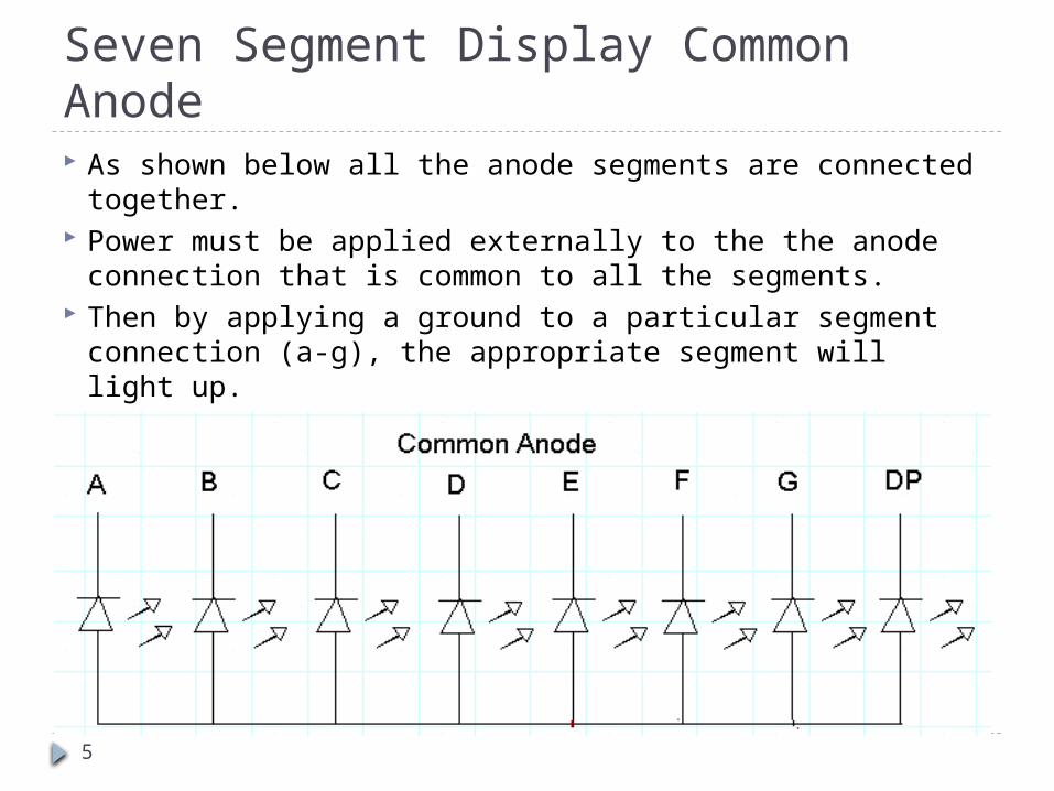
Seven Segment Display Common Anode As shown below all the anode segments are connected
together. Power must be applied externally to the the anode
connection that is common to all the segments. Then by applying a ground to a particular segment
connection (a-g), the appropriate segment will light up.

6
Seven Segment Display Common Anode
The diagram shows that the instance when power is applied to the Common Anode connection and segments b&c are grounded causing these two segments to light up.

7
Seven Segment Common Cathode As shown below all the cathode segments connected
together. For the use of this seven segment, the common
cathode connection must be grounded and power must be applied to appropriate segment in order to illuminate that segment.

8
Seven Segment Display

9
Binary Coded Decimal (BCD) Binary Coded Decimal (BCD or “8421”
BCD) numbers are made up using just 4 data bits (a nibble or half a byte) similar to the Hexadecimal numbers.
Hexadecimal numbers that range in full from 0 through to F, BCD numbers only range from 0 to 9.

10
Binary Coded Decimal (BCD)

11
BCD to Seven Segment Decoder A Digital Decoder IC, is a device which
converts one digital format into another. One of the most commonly used device for
doing this is called the Binary Coded Decimal (BCD) to 7-Segment Display Decoder.

12
BCD to Seven Segment Decoder

13
BCD to Seven Segment Decoder 74LS47 drives the common anode displays. The terminals BI/RBO and RBI stay
disconnected.

14
BCD to Seven Segment Decoder

15
BCD to Seven Segment Decoder 74LS48 drives the common cathode displays.

16
N-bit Dip Switch (Slide Style) DIP Switches are
manual electric switches that are packaged by group into a standard dual in-line package (DIP).
DIP switches are also known as toggle switches, which mean they have two possible positions on or off.

17
Testing Seven Segment Display Step - 1

18
Testing Seven Segment Display Step 2

19
Testing Seven Segment Display Step 3

20
Experiment Steps – Step 1

21
Experiment Steps – Step 2
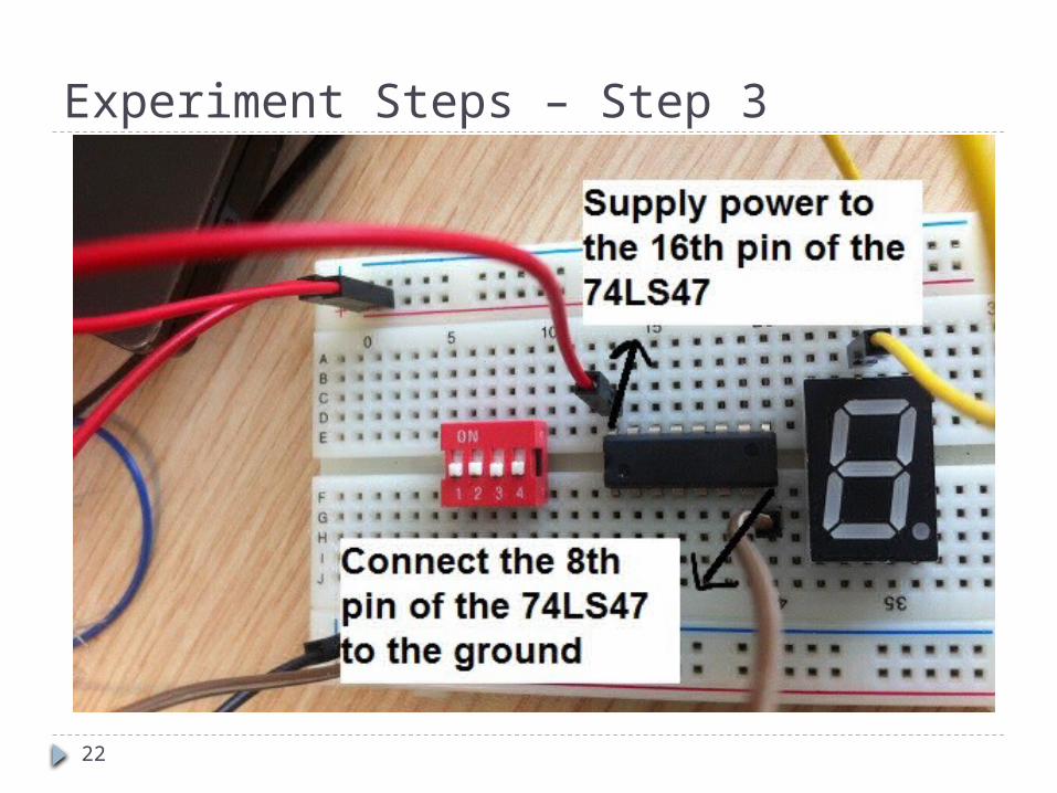
22
Experiment Steps – Step 3

23
Experiment Steps – Step 4

24
Experiment Steps – Step 4 Cont.

25
Experiment Steps – Step 4 Cont.

26
Experiment Steps – Step 4 Cont.

27
Experiment Steps – Step 5

28
Experiment Steps – Step 6

29
Experiment Steps – Step 7

30
Experiment Steps – Step 8

31
Experiment Steps – Step 8 Cont.

32
Experiment Steps – Step 8 Cont.

33
Experiment Steps – Step 8 Cont.

34
Experiment Steps – Step 8 Cont.
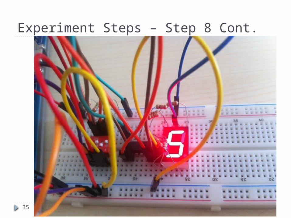
35
Experiment Steps – Step 8 Cont.

36
Experiment Steps – Step 8 Cont.

37
Experiment Steps – Step 8 Cont.

38
Experiment Steps – Step 8 Cont.

39
Experiment Steps – Step 8 Cont.