Embed Size (px)
Citation preview
Logic Control

What is Logic control
• Logic control is a control based on a logic concept, that is the on-off state of variable and/or equipment
• Logic control is often used to control combinational and/or sequential events such as lift control, automatic production line, engine start-up, etc.
• Originally used device such as switches, relay, timer, drum, and any other mechanism to enable changes of the on-off state

SWITCHES
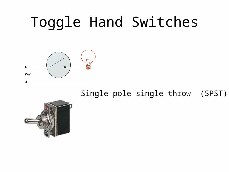
Toggle Hand Switches
~Single pole single throw (SPST)

Toggle Hand Switches
~
Single pole double throw SPDT switches
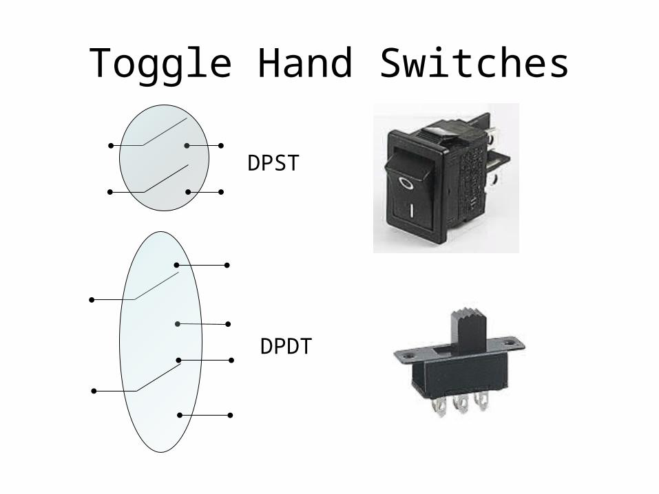
Toggle Hand Switches
DPST
DPDT

Hand Switches
3PST
Rotary Swtich

Push button Hand Switches
Normally openNO
Normally closeNC

Push-Push Switch
• This looks like a momentary action push switch but it is a standard on-off switch: – push once to switch on, – push again to switch off.
• This is called a latching action.

Microswitch
• usually SPDT • Microswitches are designed
to switch fully open or closed in response to small movements.
• They are available with levers and rollers attached.

Keyswitch
• A key operated switch.
• The example shown is SPST.

Reed Switch
• Usually SPST• The contacts of a reed switch
are closed by bringing a small magnet near the switch.
• They are used in security circuits, for example to check that doors are closed.
• Standard reed switches are SPST (simple on-off) but SPDT (changeover) versions are also available.
• reed switches have a glass body which is easily broken!

DIP Switch
• DIP = Dual In-line Parallel• This is a set of miniature
SPST on-off switches, the example shown has 8 switches.
• The package is the same size as a standard DIL (Dual In-Line) integrated circuit.
• This type of switch is used to set up circuits, e.g. setting the code of a remote control.

Multi-pole Switch
• The picture shows a 6-pole double throw switch, also known as a 6-pole changeover switch.
• It can be set to have momentary or latching action.
• Latching action means it behaves as a push-push switch, push once for the first position, push again for the second position etc.

Multi-way Switch• Multi-way switches have 3 or more conducting positions.
They may have several poles (contact sets). A popular type has a rotary action and it is available with a range of contact arrangements from 1-pole 12-way to 4-pole 3 way.
• The number of ways (switch positions) may be reduced by adjusting a stop under the fixing nut. For example if you need a 2-pole 5-way switch you can buy the 2-pole 6-way version and adjust the stop.

Process Operated Switches
• These switches is constructed using one of the above switches. A process variable will initiate a displacement to switch the switch– Limit switch– Proximity switch– Pressure switch– Level switch– Temperature switch– Flow switch– etc

SWITCH CAPACITY
• On a switch usually there is a label informing the voltage and current capacity, e.g.:
250 V5 A
• It means that:– the maximum current allowed to pass the switch is 5 A.– The maximum voltage across its terminal allowed is 250 volt
~I<5 A
~V<250 V

RELAY

Relay• A relay is an electrically
operated switch. • Current flowing through the coil
of the relay creates a magnetic field which attracts a lever and changes the switch contacts.
• The coil current can be on or off so relays have two switch positions and they are double throw (changeover) switches.
• Relay consist of coil and contact• Usually a relay has 1 coil and
many contacts both NO and NC
RELAY
coil
NO contact
NC contact

Relay
Picture is downloaded from www.kpsec.freeuk.com/components/relay.htm

Relay• In electrical diagram relay is symbolized as shown• A relay can have many contacts both NO and NC• The coil of a relay typically passes 30mA for a 12V relay, • The contacts can drive 5A or more depending on the size of
relay
RELAY SYMBOL WITH 8 CONTACTS
coilcontacts
NO NO NO NO NC NC NC NC

Relay
• Relays allow one circuit to switch a second circuit which can be completely separate from the first.
• For example a low voltage battery circuit can use a relay to switch a 220V AC mains circuit.
• There is no electrical connection inside the relay between the two circuits, the link is magnetic and mechanical. N
12 V R1
30 mA
5 AR11 R12
~ 220V

Ladder diagram

Ladder Diagram
• To make such as previous diagram easier to read a ladder diagram is used
R1
+ -
R11
S

Basic logic
AND LOGICL
+ -s1 s2
Lamp L will light if switch s1 and s2 are on.
In logic on usually symbolized as 1 and off as 0.
s1 s2 L
0 0 0
0 1 0
1 0 0
1 1 1
Mathematically written as
L = S1 AND S2

Basic logic
OR LOGIC L+ -s1
s2
Lamp L will light if switch s1 OR s2 are on.
s1 s2 L
0 0 0
0 1 1
1 0 1
1 1 1
Mathematically written as
L = S1 OR S2

Basic logic
NOT LOGIC+ -s1
Lamp L will light if not R1 is on
R1 L
0 1
1 0
R1
LR11
Mathematically written as
L = NOT(R1)

Combinational logic
Suppose you want to design a safe car with the following criteria:
The gear box (GB) will not engage unless:
1. The hand brake (HB) is released and the doors (D1-D4) are locked or
2. The safety system is disable by switching on override switch (OS) for maintenance purpose
Mathematically the above logic is written as
GB = (HB AND D1 AND D2 AND D3 AND D4) OR OS
HB D1
GB
D2 D3 D4
OS

Motor Start Stop (sequential logic)
• The following ladder diagram is used to switch a motor on and off
R1
motorR11
R12 R13 R14
S1 S2
start stop
Latching action

Auto start of water pump• Suppose that the motor is
used to drive water pump and we want that the pump can run or stop automatically depending on the water level
• In addition we also want to override the automatic control using manual start and sop control
LS

Auto start of water pump
• Off, manual and auto motor control
R1
R11motor
S1 S2
start stop
O
M
A
LS

Permissive circuits
• Often it is desired that a piece of equipment is allowed to start if several conditions are met.
• For example overload switch and over temperature switch must be closed in order the motor can be started
• Each process condition is called a permissive, and each permissive switch contact is wired in series, so that if any one of them detects an unsafe condition, the circuit will be opened.

Auto start of water pump with protection
• Suppose we want to protect the motor against over load and over temperature
R11
S1 S2
start stop
O
M
A
LS
OL OTR1
motor
S0
Permissivecircuits
Interlock circuits
• Often it is desired that only one piece of equipment is allowed to start if all other equipments are in off condition.
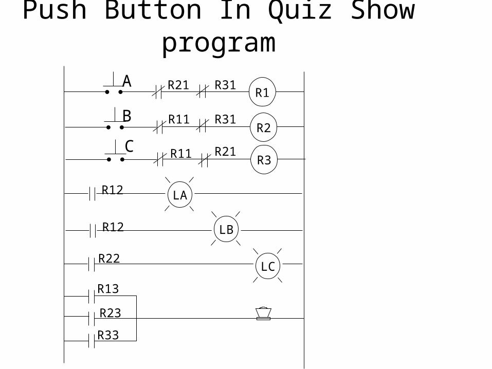
• For example push button circuit used in Quiz show program where several contestant have to answer a question.
• The first one who pushes the push button will disable the other’s push button switch
• This circuit is called interlock since acting one circuit will lock the others to function

Push Button In Quiz Show program
R1
R11
A
BR2
R21
LAR12
R22
R13
R23
LB
Push Button In Quiz Show program
R1
R11
A
BR2
R21
LBR12
R22
R13
R23
LC
LAR12
R3R11C
R31
R21
R31
R33

Push Button In Quiz Show program
R1
R11
A
BR2
R21
LBR23
R13
R23
LAR13
R12
R22
Reset
Instead of pushing the PB continually it is desired that just pushing once is enough for the contestant to claim that they are the first team pushing the buttonThe presenter must push the reset button to reset the system back to original state

InterlockAnother example of interlock is the forward circuit of motor must prevent the reverse circuit, otherwise the motor will damage
Note:Motor contactor (or "starter") coils are typically designated by the letter "M" in ladder logic diagrams.

Time delay relay• If the motor is carry a high inertia load it is dangerous to reverse the
direction of the motor instantaneously.• Time delay relay can be installed to prevent such occurrence to
happen

Fail safe design
• Consider an alarm system as shown.
• It can be design in 2 ways• Both ways work exactly in
the same manner• The second design
however gives fail save design.
• Murphy’s law is true. If something can go wrong it will.