Embed Size (px)
Citation preview

LΩGIC™ 4X36
User Manual

Edition Notes
LΩGIC™ 4X36 User Manual Rev. 10
Edition Notes The LΩGIC™ 4X36 User Manual Rev. 10 covers the description, safety precautions, installation, programming, operation, and maintenance of the LΩGIC™ 4X36. ILUMINARC® released this edition of the LΩGIC™ 4X36 User Manual Rev. 10 in May 2013.
Trademarks The ILUMINARC® logo, the ILUMINARC® name, and all other trademarks in this document related to services or products by ILUMINARC® are trademarks owned or licensed by ILUMINARC®, its affiliates, or subsidiaries. Any other product names, logos, brands, company names, or trademarks featured or referred to within this document are the property of their respective trademark holders.
Copyright Notice The entire content of this document, except where applicable and unless otherwise noted, is solely owned by ILUMINARC®, a wholly owned trademark of CHAUVET & Sons Inc.
© Copyright 2013 ILUMINARC®
All rights reserved. Electronically published by ILUMINARC® in the United States of America.
Manual Usage ILUMINARC® authorizes its customers to download and print this manual for professional information purposes only. ILUMINARC® expressly prohibits the usage, copy, storage, distribution, modification, or printing of this manual or its content for any other purpose without its written consent.
Document Printing For better results, print this document in color, on letter size paper (8.5 x 11 inches), double sided. If using A4 paper (210 x 297 mm), configure your printer to scale the content of this document to A4 paper.
Intended Audience Any person in charge of installing, operating, and/or maintaining the LΩGIC™ 4X36 should read the Guide that shipped with it and this manual in their entirety before installing, operating, or maintaining this product.
Disclaimer ILUMINARC® believes that the information contained in this manual is accurate in all respects. However, ILUMINARC® assumes no responsibility for any error or omissions in this document. ILUMINARC® reserves the right to revise this document and to make changes from time to time in the content hereof without obligation of ILUMINARC® to notify any person or company of such revision or changes. This does not constitute in any way a commitment by ILUMINARC® to make such changes. ILUMINARC® may issue a revision of this manual or a new edition of it to incorporate such changes.
Document Revision The LΩGIC™ 4X36 User Manual Rev. 10 supersedes all previous versions of this manual. Please discard any older versions of this manual you may have, whether in printed or electronic format, and replace them with this version.
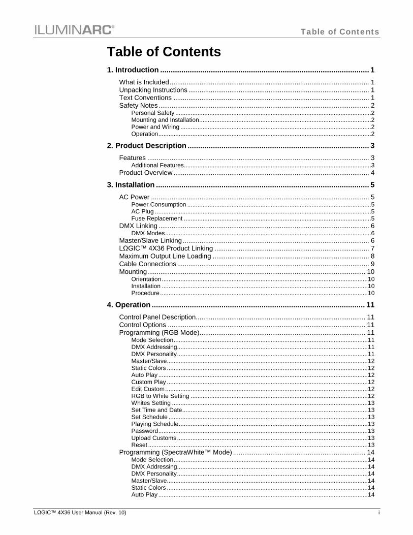
Table of Contents
LΩGIC™ 4X36 User Manual (Rev. 10) i
Table of Contents 1. Introduction ................................................................................................... 1
What is Included ........................................................................................................... 1 Unpacking Instructions ................................................................................................. 1 Text Conventions ......................................................................................................... 1 Safety Notes ................................................................................................................. 2
Personal Safety ...................................................................................................................2 Mounting and Installation .....................................................................................................2 Power and Wiring ................................................................................................................2 Operation .............................................................................................................................2
2. Product Description ...................................................................................... 3
Features ....................................................................................................................... 3 Additional Features ..............................................................................................................3
Product Overview ......................................................................................................... 4
3. Installation ..................................................................................................... 5
AC Power ..................................................................................................................... 5 Power Consumption ............................................................................................................5 AC Plug ...............................................................................................................................5 Fuse Replacement ..............................................................................................................5
DMX Linking ................................................................................................................. 6 DMX Modes .........................................................................................................................6
Master/Slave Linking .................................................................................................... 6 LΩGIC™ 4X36 Product Linking ................................................................................... 7 Maximum Output Line Loading .................................................................................... 8 Cable Connections ....................................................................................................... 9 Mounting ..................................................................................................................... 10
Orientation ......................................................................................................................... 10 Installation ......................................................................................................................... 10 Procedure .......................................................................................................................... 10
4. Operation ..................................................................................................... 11
Control Panel Description........................................................................................... 11 Control Options .......................................................................................................... 11 Programming (RGB Mode)......................................................................................... 11
Mode Selection .................................................................................................................. 11 DMX Addressing ................................................................................................................ 11 DMX Personality ................................................................................................................ 11 Master/Slave...................................................................................................................... 12 Static Colors ...................................................................................................................... 12 Auto Play ........................................................................................................................... 12 Custom Play ...................................................................................................................... 12 Edit Custom ....................................................................................................................... 12 RGB to White Setting ........................................................................................................ 12 Whites Setting ................................................................................................................... 13 Set Time and Date ............................................................................................................. 13 Set Schedule ..................................................................................................................... 13 Playing Schedule ............................................................................................................... 13 Password ........................................................................................................................... 13 Upload Customs ................................................................................................................ 13 Reset ................................................................................................................................. 13
Programming (SpectraWhite™ Mode) ....................................................................... 14 Mode Selection .................................................................................................................. 14 DMX Addressing ................................................................................................................ 14 DMX Personality ................................................................................................................ 14 Master/Slave...................................................................................................................... 14 Static Colors ...................................................................................................................... 14 Auto Play ........................................................................................................................... 14

Table of Contents
ii LΩGIC™ 4X36 User Manual (Rev. 10)
Whites Setting ................................................................................................................... 15 Set Time and Date ............................................................................................................. 15 Set Schedule ..................................................................................................................... 15 Playing Schedule ............................................................................................................... 15 Password ........................................................................................................................... 15 Reset ................................................................................................................................. 15
Menu Options RGB Mode .......................................................................................... 16 Menu Options SpectraWhite™ Mode ......................................................................... 18 DMX Values RGB Mode............................................................................................. 19
EFFECT ............................................................................................................................ 19 DMX Values RGB Mode (Cont.) ................................................................................ 20
RGB ................................................................................................................................... 20 RGB + D ............................................................................................................................ 20 RGB + DMS ....................................................................................................................... 20 RGB + LINE ....................................................................................................................... 20 RGB + LINE + DMS ........................................................................................................... 21 SOLID ................................................................................................................................ 21
DMX Values SpectraWhite™ Mode ........................................................................... 22 STUDIO W......................................................................................................................... 22 STUDIO W+D .................................................................................................................... 22 STUDIO 1 .......................................................................................................................... 22 STUDIO 2 .......................................................................................................................... 22 SOLID ................................................................................................................................ 22
5. Technical Information ................................................................................. 23
System Maintenance .................................................................................................. 23 Product Repairs .......................................................................................................... 23 Troubleshooting Guide ............................................................................................... 24 LED Disclaimer ........................................................................................................... 25
LED Life ............................................................................................................................. 25 LED Binning....................................................................................................................... 25 Color Rendering Index (CRI) ............................................................................................. 25
Returns Procedure ..................................................................................................... 26 Claims......................................................................................................................... 26 Contact Us .................................................................................................................. 26 Technical Specifications ............................................................................................. 27

Introduction
LΩGIC™ 4X36 User Manual (Rev. 10) 1
1. Introduction
This icon indicates useful, although non-
critical information.
This icon indicates important
installation or configuration information. Failure to comply with this information may prevent the product from functioning correctly.
This icon indicates critical installation,
configuration, or operation information. Failure to comply with this information may render the product partially or completely inoperative, damage third-party equipment, or cause harm to the user.
The term “DMX” used throughout this document
refers to the USITT DMX512-A transmission protocol.
What is Included · One LΩGIC™ 4X36 · One RJ-45 to 3-pin DMX male adapter (input) · One RJ-45 to 3-pin DMX female adapter (output) · Four RJ-45 coupler · One Power Cord · Warranty Card · Quick Start Guide
Unpacking Instructions Immediately upon receiving a product from ILUMINARC®, carefully unpack the carton. Check the contents of the box to ensure that all parts are present and that they are in good condition. If any part appears damaged from shipping, or if the carton shows signs of mishandling, see the Claims section in the Technical Information chapter.
Text Conventions Convention Meaning
1~512 A range of values in the text 50/60 A set of mutually exclusive values in the text
“ILUMICON UM” The name of another publication or manual <SET> A button on the products control panel Settings A product function or a menu option
MENU > Settings A sequence of menu options 1~10 A range of menu values from which to choose in a menu
Yes/No A set of two mutually exclusive menu options in a menu ON A unique value to enter or select in a menu
Introduction
2 LΩGIC™ 4X36 User Manual (Rev. 10)
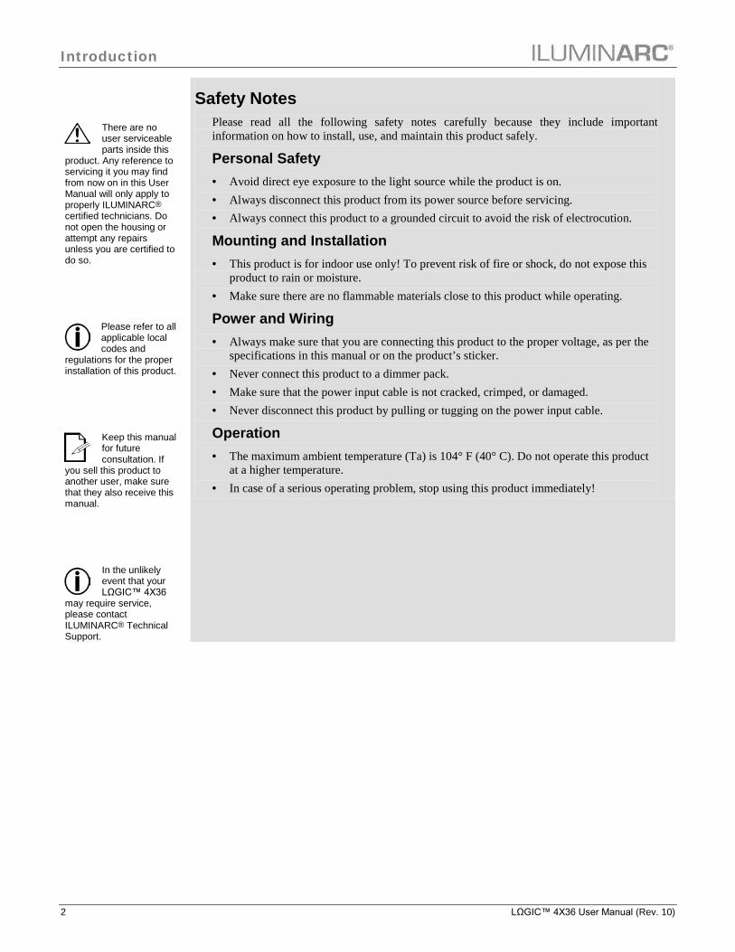
There are no user serviceable parts inside this
product. Any reference to servicing it you may find from now on in this User Manual will only apply to properly ILUMINARC® certified technicians. Do not open the housing or attempt any repairs unless you are certified to do so.
Please refer to all applicable local codes and
regulations for the proper installation of this product.
Keep this manual for future consultation. If
you sell this product to another user, make sure that they also receive this manual.
In the unlikely event that your LΩGIC™ 4X36
may require service, please contact ILUMINARC® Technical Support.
Safety Notes Please read all the following safety notes carefully because they include important information on how to install, use, and maintain this product safely.
Personal Safety · Avoid direct eye exposure to the light source while the product is on. · Always disconnect this product from its power source before servicing. · Always connect this product to a grounded circuit to avoid the risk of electrocution.
Mounting and Installation · This product is for indoor use only! To prevent risk of fire or shock, do not expose this
product to rain or moisture. · Make sure there are no flammable materials close to this product while operating.
Power and Wiring · Always make sure that you are connecting this product to the proper voltage, as per the
specifications in this manual or on the product’s sticker. · Never connect this product to a dimmer pack. · Make sure that the power input cable is not cracked, crimped, or damaged. · Never disconnect this product by pulling or tugging on the power input cable.
Operation · The maximum ambient temperature (Ta) is 104° F (40° C). Do not operate this product
at a higher temperature. · In case of a serious operating problem, stop using this product immediately!

Product Description
LΩGIC™ 4X36 User Manual (Rev. 10) 3
2. Product Description
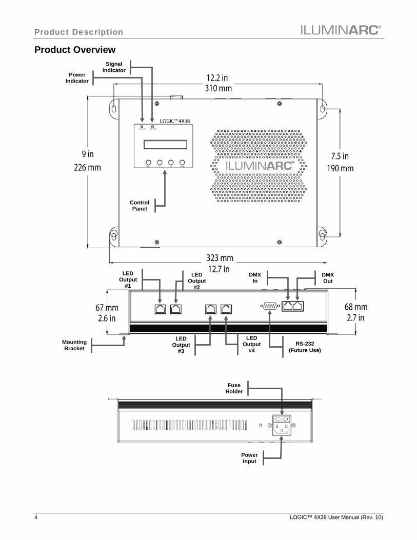
The LΩGIC™ 4X36 unit is the power supply and control for the LΩGIC™ series of devices. The LΩGIC™ 4X36 consists of seven (7) personalities for the RGB mode and five (5) personalities for the SpectraWhite™ mode, all of which are configurable from the control panel. The output is four RJ-45 type connections. The DMX input and output are on the rear panel and also use a RJ-45 type connection.
Features · 1, 2, 3, 4, 5, 6, 9, 12, or 15-channel DMX control · Operating modes:
RGB 1-channel: RGB, dimmer (no individual RGB adjustments) 3-channel: RGB control (individual RGB adjustments) 4-channel: RGB control, dimmer 6-channel: RGB control, dimmer, color macro, strobe 9-channel: RGB control, dimmer, color macro, strobe, auto + custom, auto speed, zone
selection 12-channel: RGB control, line control 15-channel: RGB control, line control, dimmer, color macro, strobe
SpectraWhite™ 1-channel: White dimmer 2-channel: White control (warm + cool) 2-channel: White macro, dimmer 3-channel: White control (warm + cool), dimmer 5-channel: White control (warm + cool), macro, dimmer
· RGB color mixing with or without DMX control (RGB mode) · White effects mixing with or without DMX control (SpectraWhite™ mode) · Automated and customizable programs (RGB mode) · Recall auto and custom programs via master/slave or DMX
Additional Features · Master/Slave (RJ-45) · Static Playing · RGB and white color calibration · Schedule playback with time clock functions · LCD display with password protection
Product Description
4 LΩGIC™ 4X36 User Manual (Rev. 10)
Product Overview
Signal Indicator
Power Indicator
DMX In
DMX Out
LED Output
#1
RS-232 (Future Use)
Control Panel
Power Input
Mounting Bracket
Fuse Holder
LED Output
#2
LED Output
#3
LED Output
#4
Installation
LΩGIC™ 4X36 User Manual (Rev. 10) 5
3. Installation
Always connect the LΩGIC™ 4X36 to a
protected circuit with an appropriate electrical ground to avoid the risk of electrocution or fire.
Never connect the LΩGIC™ 4X36 to a
rheostat (variable resistor) or dimmer circuit, even if the rheostat or dimmer channel serves only as a 0 to 100% switch.
Make sure to disconnect the products power
cord before replacing a blown fuse, and always replace it with a fuse of the same type and rating.
AC Power The LΩGIC™ 4X36 has an auto-ranging power supply that can work with an input voltage range of 100~240 VAC, 50/60 Hz. Make sure that you are connecting this product to the proper voltage, as per the specifications in this guide, the product’s user manual, or on the product’s sticker.
Power Consumption To determine the power requirements for the LΩGIC™ 4X36 see the label affixed to the side of the product. Alternatively, you may refer to the corresponding specifications chart in the Technical Information chapter of this manual. The listed current rating indicates the maximum current draw during normal operation.
AC Plug The LΩGIC™ 4X36 comes with a power input cord terminated with an IEC connector on one end and an Edison plug on the other end (US market). If the power cord that came with your product has no plug or you need to change the Edison plug, use the table below to wire the new plug.
Connection Wire (US) Screw Color (US) Wire (Europe)
AC Live Black Yellow or Brass Brown AC Neutral White Silver or Gray Blue AC Ground Green/Yellow Green Green/Yellow
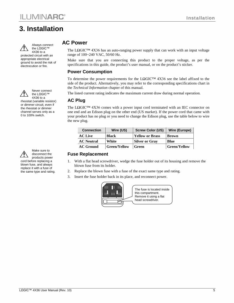
Fuse Replacement 1. With a flat head screwdriver, wedge the fuse holder out of its housing and remove the
blown fuse from its holder. 2. Replace the blown fuse with a fuse of the exact same type and rating. 3. Insert the fuse holder back in its place, and reconnect power.
The fuse is located inside this compartment. Remove it using a flat head screwdriver.
Installation
6 LΩGIC™ 4X36 User Manual (Rev. 10)
The products must be linked using DMX cable
in a daisy chain (serial) fashion. To comply with the EIA-485 standard, no more than 32 products should be connected on one daisy chain without using a DMX optically-isolated splitter. Doing otherwise may result in deterioration of the digital DMX signal.
USITT recommends limiting the total
length of the DMX cable (from the first product/controller to the last product) to 300 ~ 455 m (985 ~ 1,500 ft).
The Operation chapter of this manual provides
detailed instructions on how to configure the Master and Slave products.
DMX Linking The LΩGIC™ 4X36 uses a CAT5 cable to link to other units. · The first unit of each set of LΩGIC™ 4X36 units must connect to the DMX controller
with a CAT5 to XLR male adapter. · The last LΩGIC™ 4X36 unit must use a CAT5 to XLR female adapter to continue the
serial link to other DMX compatible units. You may link the LΩGIC™ 4X36 to a DMX controller using a CAT5 cable. If using other DMX compatible products with the LΩGIC™ 4X36, it is possible to control them individually with a single DMX controller. If you are not familiar with the DMX standard, or if you need information about the DMX cables needed to link the LΩGIC™ 4X36 to a DMX controller, you may download the “DMX Primer” document from the ILUMINARC® web site: www.iluminarc.com.
DMX Modes The LΩGIC™ 4X36 uses the CAT5 DMX data connection for its two DMX modes (SpectraWhite™ and RGB). These modes contain their own separate personalities. Refer to the Introduction chapter for a brief description of these modes and the Operation chapter to learn how to configure the LΩGIC™ 4X36 to work in these modes. The DMX Values section will give you detailed information regarding the above-mentioned DMX modes.
Master/Slave Linking The LΩGIC™ 4X36 supports master/slave mode. Several DMX compatible units can be synchronized without a DMX controller in master/slave operating mode. The Master/Slave mode allows a LΩGIC™ 4X36 unit (the master) running a preconfigured program to control several other LΩGIC™ 4X36 units (the slaves) without requiring a DMX controller. In this mode, all the slave units will operate in unison with the master unit. When in Master/Slave mode, the LΩGIC™ 4X36 units link to each other using the standard CAT5 connection.
Installation
LΩGIC™ 4X36 User Manual (Rev. 10) 7
Do not use the splitter as a coupler. All cables must be terminated to a fixture.
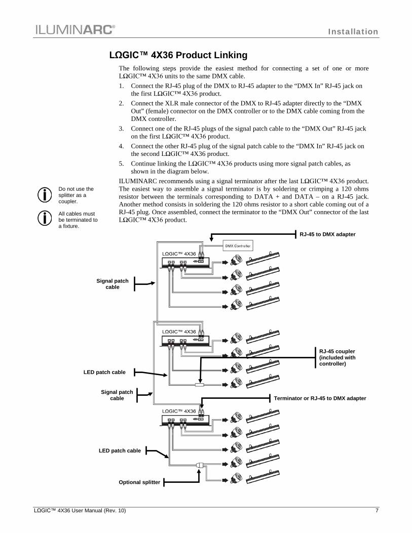
LΩGIC™ 4X36 Product Linking The following steps provide the easiest method for connecting a set of one or more LΩGIC™ 4X36 units to the same DMX cable. 1. Connect the RJ-45 plug of the DMX to RJ-45 adapter to the “DMX In” RJ-45 jack on
the first LΩGIC™ 4X36 product. 2. Connect the XLR male connector of the DMX to RJ-45 adapter directly to the “DMX
Out” (female) connector on the DMX controller or to the DMX cable coming from the DMX controller.
3. Connect one of the RJ-45 plugs of the signal patch cable to the “DMX Out” RJ-45 jack on the first LΩGIC™ 4X36 product.
4. Connect the other RJ-45 plug of the signal patch cable to the “DMX In” RJ-45 jack on the second LΩGIC™ 4X36 product.
5. Continue linking the LΩGIC™ 4X36 products using more signal patch cables, as shown in the diagram below.
ILUMINARC recommends using a signal terminator after the last LΩGIC™ 4X36 product. The easiest way to assemble a signal terminator is by soldering or crimping a 120 ohms resistor between the terminals corresponding to DATA + and DATA – on a RJ-45 jack. Another method consists in soldering the 120 ohms resistor to a short cable coming out of a RJ-45 plug. Once assembled, connect the terminator to the “DMX Out” connector of the last LΩGIC™ 4X36 product.
RJ-45 to DMX adapter
LED patch cable
Signal patch cable
LED patch cable
RJ-45 coupler (included with controller)
Terminator or RJ-45 to DMX adapter
Signal patch cable
Optional splitter

Installation
8 LΩGIC™ 4X36 User Manual (Rev. 10)
When connecting LΩGIC™ products to the
LΩGIC™ 4X36 controller, do not exceed the maximum of 12 LEDs per output channel (36 LEDs total for the output line).
Maximum Output Line Loading The LΩGIC™ 4X36 product has four output lines. This means that the user can combine various output lines to create zones. Each output line has three channels whose names change depending on the selected operation mode. · RGB mode: Red, Green, and Blue · SpectraWhite™ mode: Warm, Natural, and Cool
Each channel can support up to twelve (12) LEDs. As a result, the maximum number of LEDs supported by an output line is 36. Inside the LΩGIC™ products, the LEDs are grouped in clusters of three LEDs each. In an LED cluster, each LED connects to an individual output channel from the LΩGIC™ product. When a product has more than one cluster, the same output channel supports as many LEDs as clusters the product has. Please see the guide below for the output line loading. This table shows the maximum number of a single type of products that can be loaded onto each of the LΩGIC™ 4X36’s output lines.
MODEL NAME TOTAL LED’S MAX. NUMBER OF
CONNECTED PRODUCTS PER OUTPUT
Ilumiline LΩGIC™ 36 RGB 36 1
Ilumiline LΩGIC™ 24 RGB 24 1
Ilumiline LΩGIC™ 24 Optic RGB 24 1
Ilumiline LΩGIC™ 12 Optic 12 3
Ilumiline LΩGIC™ 12 12 3
Ilumipod LΩGIC™ 12 Optic 12 3
Ilumipod LΩGIC™ Tri-4 12 3
Ilumipod LΩGIC™ 6 Optic 6 6
Ilumipod LΩGIC™ 3 Optic 3 12
Ilumipod LΩGIC™ Tri-1 3 12
You may also combine different products together, as long as you do not exceed the maximum of 36 LEDs per output line. Please see the following example of a possible combination.
Ilumipod LΩGIC™ Tri-4 12 X 2 = 24 2 products
Ilumipod LΩGIC™ 6 Optic 6 x 2 = 12 2 products
Total 36 LEDs 4 products

Installation
LΩGIC™ 4X36 User Manual (Rev. 10) 9
Cable Connections
RJ-45 Plug 3-pin XLR Male 5-pin XLR Male Pin 1: Not Used Pin 2: Not Used Pin 3: Not Used Pin 4: Not Used Pin 4: Not Used Pin 5: +5 V Pin 5: Not Used Pin 6: Data + Pin 3: Data + Pin 3: Data + Pin 7: Data - Pin 2: Data - Pin 2: Data - Pin 8: GND Pin 1: GND Pin 1: GND
RJ-45 Plug RJ-45 Plug
Pin 1: Not Used Pin 1: Not Used Pin 2: Not Used Pin 2: Not Used
Pin 3: Not Used Pin 3: Not Used
Pin 4: Not Used Pin 4: Not Used
Pin 5: +5 V Pin 5: +5 V
Pin 6: Data + Pin 6: Data + Pin 7: Data - Pin 7: Data -
Pin 8: GND Pin 8: GND
Pin # Wire Color Function 1 White/Orange Red LED + 2 Orange/White Green LED + 3 White/Green Blue LED + 4 Blue/White Not Used 5 White/Blue Red LED - 6 Green/White Green LED - 7 White/Brown Blue LED - 8 Brown/White Not Used
XLR (male) 3-pin
Signal Patch cable: Used for linking two LΩGIC™ 4X36products
LED Patch Cable: Used to link the LΩGIC™ 4X36 to its products.
RJ-45 Plug DMX XLR (male)
XLR (male) 5-pin RJ-45 Plug Pin Assignment
View facing pins
Installation
10 LΩGIC™ 4X36 User Manual (Rev. 10)
Make sure to mount this product away
from any flammable material as indicated in the Safety Notes.
Please consult local electrical code compliance
and regulations for any additional installation restrictions.
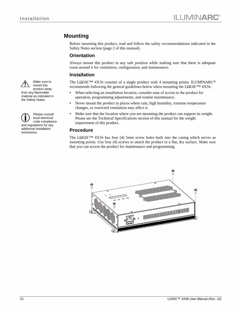
Mounting Before mounting this product, read and follow the safety recommendations indicated in the Safety Notes section (page 2 of this manual).
Orientation Always mount this product in any safe position while making sure that there is adequate room around it for ventilation, configuration, and maintenance.
Installation The LΩGIC™ 4X36 consists of a single product with 4 mounting points. ILUMINARC® recommends following the general guidelines below when mounting the LΩGIC™ 4X36. · When selecting an installation location, consider ease of access to the product for
operation, programming adjustments, and routine maintenance. · Never mount the product in places where rain, high humidity, extreme temperature
changes, or restricted ventilation may affect it. · Make sure that the location where you are mounting the product can support its weight.
Please see the Technical Specifications section of this manual for the weight requirement of this product.
Procedure The LΩGIC™ 4X36 has four (4) 5mm screw holes built into the casing which serves as mounting points. Use four (4) screws to attach the product to a flat, dry surface. Make sure that you can access the product for maintenance and programming.

Operation
LΩGIC™ 4X36 User Manual (Rev. 10) 11
4. Operation
When running the product using a DMX
controller, make sure that the Menu>Run is set to DMX.
Control Panel Description Button Function
<MENU> Exits from the current menu or function
<SET> Enables the currently displayed menu or sets the currently selected value in to the current function
<UP> Navigates upwards through the menu list and increases the numeric value when in a function
<DOWN> Navigates downwards through the menu list and decreases the numeric value when in a function
Control Options You can set the LΩGIC™ 4X36 start address in the 001~512 DMX range. This allows for the control of up to 34 products in the 15-channel RGB+LINE+DMS personality.
Programming (RGB Mode) Refer to the Menu Options section to learn how the menu options relate to each other. The Menu Options section has a Main level and a variable number of programming levels for each option. · To go to an option in the Main level, press <MENU> repeatedly until the option
shows on the display. Press <SET> to select. This will take you to the first programming level for that option.
· To select an option or value within the current programming level, press <UP> or <DOWN> until the option or value is displayed. Press <SET> to accept. If there is another programming level, you will see that level’s first option. If not, you will see the selected value.
· To exit to the previous menu level, press <MENU>.
Mode Selection 1. Go to MENU>SETTINGS. 2. Select GOTO RGB. 3. Select YES?
DMX Addressing 1. Go to MENU>DMX ADDRESS. 2. Select the starting address [001~512]. 3. Go to MENU >OPERATION. 4. Select DMX.
DMX Personality 1. Go to MENU>PERSONALITY and select any DMX personality. 2. Make sure to rearrange the DMX addresses of all products in the current DMX universe
to avoid address overlapping.

Operation
12 LΩGIC™ 4X36 User Manual (Rev. 10)
AUTO 01~10 are fully configured programs and
cannot be modified. However, CUSTOM 01~10 programs are fully customizable (see Edit Custom).
AUTO 01~10 consist of two (2) different, fully
configured programs giving the user a total of twenty(20) different auto programs to choose from.
Master/Slave On the Master product: 1. Go to MENU>OPERATION and select DMX. 2. Go to MENU>PLAY AUTO and select any Auto program. On each of the Slave products: 1. Go to MENU>OPERATION and select SLAVE. The slave products will follow the program played by the Master.
Static Colors 1. Go to MENU>PLAY STATIC. 2. Select an output line L [1~4] 3. Select a color or effect RED, GREEN, BLUE, DIMMER, and STROBE. 4. Select a color value [000~255] or a strobe frequency [0~20].
Auto Play 1. Go to MENU>PLAY AUTO. 2. Select a program RGB, or RGBL [01~10]. 3. Select a speed SP [001~255].
Custom Play 1. Go to MENU>CUSTOM. 2. Select a program CUSTOM [01~10].
Edit Custom 1. Go to MENU>EDIT. 2. Select a program C-[01~10]. 3. Select a scene S-[01~20]. 4. Select a color R, G, or B. 5. Configure the color value [000~255]. 6. Repeat steps 4 and 5 for the other colors. 7. Configure the strobe frequency S [00~20]. 8. Configure the Step and Fade timers [000~255]. 9. Repeat steps 4 to 8 for the other scenes.
RGB to White Setting When RGB TO W is active, the product will automatically use the RGB values for a balanced white look. When inactive, the product will use the most powerful intensity. 1. Go to MENU>SETTTINGS>RGB TO WHITE. 2. Select YES or NO.

Operation
LΩGIC™ 4X36 User Manual (Rev. 10) 13
Whites Setting 1. Go to MENU>SETTINGS>CALIBRATION. 2. Select a white color WHITE 1~9 or RGB TO WHITE. 3. Set a color R, G, or B. 4. Configure the color value [000~255]. 5. Repeat steps 2 thru 4 for the other RGB colors to obtain a white color.
Set Time and Date 1. Go to MENU>SETTINGS>CLOCK>EDIT TIME. 2. Set Year, Day Of Week, Day, Month, Hour, Min, and Sec.
Set Schedule 1. Go to MENU>SCHEDULE. A day of the week or “EVERYDAY” will show on the
LCD. 2. Select DOW or EVERYDAY. 3. Select NO. [01~10]. 4. Set CUSTOM [01~10], STATIC, RGBL [01~10], RGB [01~10], or PLAY NONE. 5. Set Start time [00:00 to 23:59].
Set End time [00:00 to 23:59].
Playing Schedule 1. Go to MENU>PLAY SCHEDULE.
The Password is fixed by default. It is not able to
be changed.
If the upload is successful, all the
products will show ”Success” on the LCD.
Password When KEYLOCK is active, the product will ask you to enter the password (<UP>, <DOWN>, <UP>, and <DOWN>) after 30 seconds of control panel inactivity or upon power up. 1. Go to MENU >SETTINGS. 2. Select ON/OFF.
Upload Customs 1. Set all products that are going to receive the upload to SLAVE operation. 2. Disconnect the products from the DMX controller. 3. On the product whose custom programs you are going to copy, got to MENU
>SETTINGS and select UPLOAD. 4. Enter the password and press <SET>for the upload to start.
Reset 1. Go to MENU>SETTINGS. 2. Select RESET CUSTOM (resets custom programs), RESET SCHEDULE (resets
schedule), or RESET ALL (resets entire product to factory default). 3. When YES shows, press <SET>.

Operation
14 LΩGIC™ 4X36 User Manual (Rev. 10)
Programming (SpectraWhite™ Mode) Refer to the Menu Options section on page 20 to learn how the menu options relate to each other. The Menu Options section has a Main level and a variable number of programming levels for each option.
· To go to an option in the Main level, press <MENU> repeatedly until the option shows on the display. Press <SET> to select it. This will take you to the first programming level for that option.
· To select an option or value within the current programming level press <UP> or <DOWN> until it shows on the display. Press <SET> to accept it. In this case, if there is another programming level, you will see its first option. Otherwise, you will see the selected value.
· To exit to the previous menu level, press <MENU>.
Mode Selection 1. Go to MENU>SETTINGS. 2. Select GOTOWHITE. 3. Select YES?
DMX Addressing 1. Go to MENU >DMX ADDRESS. 2. Select the starting address [001~512]. 3. Go to MENU >OPERATION. 4. Select DMX.
DMX Personality 1. Go to MENU>PERSONALITY and select any DMX personality. 2. Make sure to rearrange the DMX addresses of all products in the current DMX universe
to avoid address overlapping.
Master/Slave On the Master product: 1. Go to MENU>OPERATION and select DMX. 2. Go to MENU>MOOD. 3. Select COOL, WARM, or NATURAL. 4. Select DIM[000~255] On each of the Slave products: 1. Go to MENU>OPERATION and select SLAVE. The slave products will follow the program played by the Master.
Static Colors 1. Go to MENU>PLAYSTATIC. 2. Select an output line L [1~4]. 3. Select a color or effect COOL, WARM, DIMMER, and STROBE. 4. Select a color value [000~255] or a strobe frequency [00~20]
Auto Play 1. Go to MENU>MOOD. 2. Select a program COOL, WARM, or NATURAL. 3. Select DIM [000~255].

Operation
LΩGIC™ 4X36 User Manual (Rev. 10) 15
Whites Setting 1. Go to MENU>SETTINGS>CALIBRATION. 2. Select a white macro WHITE [1~5]. 3. Configure the color value for WARM and COOL [000~255]. 4. Repeat steps 2 and 3 for the other white macros.
Set Time and Date 1. Go to MENU>SETTINGS>EDIT TIME. 2. Set Year, Day Of Week, Day, Month, Hour, Min, and Sec.
Set Schedule 1. Go to MENU>SCHEDULE. A day of the week or “EVERYDAY” will show on the
LCD. 2. Select DOW or EVERYDAY. 3. Select NO [01~10]. 4. Set WHITE [1~5] or PLAY NONE. 5. Set Start time [00:00 to 23:59].
Set End time [00:00 to 23:59].
Playing Schedule 1. Go to MENU>PLAY SCHEDULE.
Password When KEYLOCK is active, the product will ask you to enter the password (<UP>, <DOWN>, <UP>, and <DOWN>) after 30 seconds of control panel inactivity or upon power up. 1. Go to MENU >SETTINGS. 2. Select ON/OFF.
Reset 1. Go to MENU>SETTINGS. 2. Select RESET ALL (sets product back to factory default settings). 3. When YES shows, press <SET>.

Operation
16 LΩGIC™ 4X36 User Manual (Rev. 10)
Menu Options RGB Mode
Main Programming Steps Instructions
1. Play auto RGB 1~10 RGBL 1~10 SPEED 1~255 Choose from 10 automatic programs 2. Play custom CUSTOM 1~10 Choose from 10 user-defined programs
3. Play Static L1~4
RED
0~255 Configure and/or play a single step program
GREEN
BLUE
DIMMER
STROBE 0~20 4. Play schedule SCHEDULE PLAYING! Play scheduled program
5. DMX address 001~512 Sets DMX starting address
6. Personality
EFFECT 9-channel mode
RGB 3-channel mode
RGB+D 4-channel mode
RGB+DMS 6-channel mode
RGB+LINE 12-channel RGB control over individual lines
RGB+LINE+DMS 15-channel RGB control over individual lines + dimmer, color macro + strobe
SOLID 1-channel mode
7. Edit custom
C-1~10 (custom)
S-1~20 (scene)
R G B
0~255 Combine Red, Green, and Blue to generate a custom color
S 0~20 Set the strobe frequency
T 0~255
Set the on time
F Set the fading time
8. Settings
PASSWORD ON/OFF Turn password protection on after 30 seconds of being idle
ALLOW EDIT
YES/NO
Reserved for future use
RESET ALL Default all settings
RESET CUSTOM Erase the custom programs
RESET SCHEDULE Erase the schedule
UPLOAD PASSWORD? [Enter Password] Transfer custom programs from master to slave products
CLOCK
TIME NOW View the DOW, date, and time
EDIT TIME
YEAR 00~99
Edit the DOW, date, and time
DOW SU~SA
DAY 01~31
MONTH 00~12
HOUR 00~23
MIN 00~59
SEC
CALIB-RATION
WHITE 1~9 R G B
0~255 Modify the White macros
RGB TO WHITE Configure RGB to WHITE values
RGB TO WHITE YES/NO [Yes]RGB TO WHITE defines output color when RGB faders are at “255” [No]Max. intensity when RGB faders are at “255”
GO TO WHITE YES? Go to SpectraWhite™ mode Continues on the next page
Operation
LΩGIC™ 4X36 User Manual (Rev. 10) 17
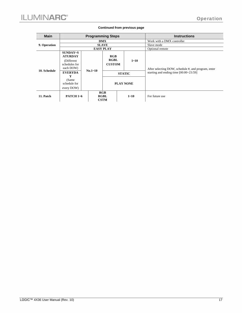
Continued from previous page
Main Programming Steps Instructions
9. Operation DMX Work with a DMX controller
SLAVE Slave mode EASY PLAY Optional remote
10. Schedule
SUNDAY~SATURDAY (Different
schedules for each DOW)
No.1~10
RGB RGBL
CUSTOM 1~10
After selecting DOW, schedule #, and program, enter starting and ending time [00:00~23:59] EVERYDA
Y (Same
schedule for every DOW)
STATIC
PLAY NONE
11. Patch PATCH 1~6 RGB
RGBL CSTM
1~10 For future use

Operation
18 LΩGIC™ 4X36 User Manual (Rev. 10)
Menu Options SpectraWhite™ Mode
Main Programming Steps Instructions
1. Mood WARM
DIM 1~255 Choose a white effect and intensity NATURAL COOL
2. Play Static L1~4
COOL 0~255 Configures and/or plays a single step program per output
line WARM
DIMMER STROBE 0~20
3. Play schedule SCHEDULE PLAYING! Playscheduled program
4. DMX Address 001~512 Sets DMX starting address
5. Personality
STUDIO W 2-channel mode STUDIO W+D 3-channel mode
STUDIO 1 2-channel mode STUDIO 2 4-channel mode
SOLID 1-channel mode
6. Settings
PASSWORD ON/OFF Turns password protection on after 30 seconds of being idle
RESET ALL YES/NO Defaults all settings CALIB-
RATION WHITE 1~5 WARM 0~255 Modify the White macros COOL TIME NOW View the DOW, date, and time
EDIT TIM
YEAR 2000~2099
Edit the DOW, date, and time
DOW SA~SU DAY 01~31
MONTH 01~12 HOUR 00~23 MIN 00~59 SEC
GO TO RGB YES? Go to RGB mode
7. Operation DMX Work with a DMX controller SLAVE Slave mode with Master product
8. Schedule
SUNDAY~SATURDAY (Different schedules for each
DOW) No. 1~10 WHITE 1~5 After selecting DOW, schedule #, and white macro; enter starting and ending time [00:00~23:59] EVERYDAY
(Same schedule every DOW)

Operation
LΩGIC™ 4X36 User Manual (Rev. 10) 19
DMX Values RGB Mode EFFECT
Channel Function Value Percent/Setting
1 Red 000 ó 255
0~100% Step Time When CUS. 01-10 in CH. 7 is activated
2 Green 000 ó 255
0~100% Step Time When CUS. 01-10 in CH. 7 is activated
3 Blue 000 ó 255 0~100% 4 Dimmer 000 ó 255 0~100%
5 Color Macro + White Balance
000 ó 010 011 ó 035 036 ó 060 061 ó 085 086 ó 110 111 ó 135 136 ó 160 161 ó 185 186 ó 210 211 ó 215 216 ó 220 221 ó 225 226 ó 230 231 ó 235 236 ó 240 241 ó 245 246 ó 250 251 ó 255
No Function R: 100% G: Up B: 0% R: Down G: 100% B: 0% R: 0% G: 100% B: Up R: 0% G: Down B: 100% R: Up G: 0% B: 100% R: 100% G: 0% B: Down R: 100% G: Up B: Up R: Down G: Down B: 100% White 1: 3,200 K White 2: 3,400 K White 3: 4,200 K White 4: 4,900 K White 5: 5,600 K White 6: 5,900 K White 7: 6,500 K White 8: 7,200 K White 9: 8,500 K
6 Strobe 000 ó 004 005 ó 255
No Function 0~20 Hz
7 Auto + Custom Programs
000 ó 020 021 ó 030 031 ó 040 041 ó 050 051 ó 060 061 ó 070 071 ó 080 081 ó 090 091 ó 100 101 ó 110 111 ó 120 121 ó 130 131 ó 140 141 ó 150 151 ó 160 161 ó 170 171 ó 180 181 ó 190 191 ó 200 201 ó 210 211 ó 220 221 ó 255
No function Auto RGB 1 Auto RGB 2 Auto RGB 3 Auto RGB 4 Auto RGB 5 Auto RGBL 1 Auto RGBL 2 Auto RGBL 3 Auto RGBL 4 Auto RGBL 5 Custom 1 Custom 2 Custom 3 Custom 4 Custom 5 Custom 6 Custom 7 Custom 8 Custom 9 Custom 10 No function
8 Auto Programs Speed 000 ó 255 Slow~fast
9 Zone Selection
000 ó 009 010 ó 029 030 ó 049 050 ó 069 070 ó 089 090 ó 109 110 ó 129 130 ó 149 150 ó 169 170 ó 189 190 ó 209 210 ó 219 220 ó 229 230 ó 239 240 ó 249 250 ó 255
All Lines Line 1 Line 2 Line 3 Line 4 Line 1,2 Line 2,3 Line 3,4 Line 1,4 Line 1,3 Line 2,4 Line 1,2,3 Line 2,3,4 Line 1,2,4 Line 1,3,4 All Lines

Operation
20 LΩGIC™ 4X36 User Manual (Rev. 10)
DMX Values RGB Mode (Cont.) RGB
Channel Function Value Percent/Setting 1 Red 000 ó 255 0~100% 2 Green 000 ó 255 0~100% 3 Blue 000 ó 255 0~100%
RGB + D Channel Function Value Percent/Setting
1 Red 000 ó 255 0~100% 2 Green 000 ó 255 0~100% 3 Blue 000 ó 255 0~100% 4 Dimmer 000 ó 255 0~100%
RGB + DMS Channel Function Value Percent/Setting
1 Red 000 ó 255 0~100% 2 Green 000 ó 255 0~100% 3 Blue 000 ó 255 0~100% 4 Dimmer 000 ó 255 0~100%
5 Color Macro + White Balance
000 ó 010 011 ó 035 036 ó 060 061 ó 085 086 ó 110 111 ó 135 136 ó 160 161 ó 185 186 ó 210 211 ó 215 216 ó 220 221 ó 225 226 ó 230 231 ó 235 236 ó 240 241 ó 245 246 ó 250 251 ó 255
No Function R: 100% G: Up B: 0% R: Down G: 100% B: 0% R: 0% G: 100% B: Up R: 0% G: Down B: 100% R: Up G: 0% B: 100% R: 100% G: 0% B: Down R: 100% G: Up B: Up R: Down G: Down B: 100% White 1: 3,200 K White 2: 3,400 K White 3: 4,200 K White 4: 4,900 K White 5: 5,600 K White 6: 5,900 K White 7: 6,500 K White 8: 7,200 K White 9: 8,500 K
6 Strobe 000ó 255 0~20 Hz
RGB + LINE Channel Function Value Percent/Setting
1 Red - 1 000 ó 255 0~100% 2 Green - 1 000 ó 255 0~100% 3 Blue - 1 000 ó 255 0~100% 4 Red - 2 000 ó 255 0~100% 5 Green - 2 000 ó 255 0~100% 6 Blue - 2 000 ó 255 0~100% 7 Red - 3 000 ó 255 0~100% 8 Green - 3 000 ó 255 0~100% 9 Blue - 3 000 ó 255 0~100% 10 Red - 4 000 ó 255 0~100% 11 Green - 4 000 ó 255 0~100% 12 Blue - 4 000 ó 255 0~100%

Operation
LΩGIC™ 4X36 User Manual (Rev. 10) 21
RGB + LINE + DMS Channel Function Value Percent/Setting
1 Red - 1 000 ó 255 0~100% 2 Green - 1 000 ó 255 0~100% 3 Blue - 1 000 ó 255 0~100% 4 Red - 2 000 ó 255 0~100% 5 Green - 2 000 ó 255 0~100% 6 Blue - 2 000 ó 255 0~100% 7 Red - 3 000 ó 255 0~100% 8 Green - 3 000 ó 255 0~100% 9 Blue - 3 000 ó 255 0~100% 10 Red - 4 000 ó 255 0~100% 11 Green - 4 000 ó 255 0~100% 12 Blue - 4 000 ó 255 0~100% 13 Dimmer 000 ó 255 0~100%
14 Color Macro + White Balance
000 ó 010 011 ó 035 036 ó 060 061 ó 085 086 ó 110 111 ó 135 136 ó 160 161 ó 185 186 ó 210 211 ó 215 216 ó 220 221 ó 225 226 ó 230 231 ó 235 236 ó 240 241 ó 245 246 ó 250 251 ó 255
No Function R: 100% G: Up B: 0% R: Down G: 100% B: 0% R: 0% G: 100% B: Up R: 0% G: Down B: 100% R: Up G: 0% B: 100% R: 100% G: 0% B: Down R: 100% G: Up B: Up R: Down G: Down B: 100% White 1: 3,200 K White 2: 3,400 K White 3: 4,200 K White 4: 4,900 K White 5: 5,600 K White 6: 5,900 K White 7: 6,500 K White 8: 7,200 K White 9: 8,500 K
15 Strobe 000ó 255 0~20 Hz
SOLID Channel Function Value Percent/Setting
1 Master Dimmer 000 ó 255 0~100%
Operation
22 LΩGIC™ 4X36 User Manual (Rev. 10)
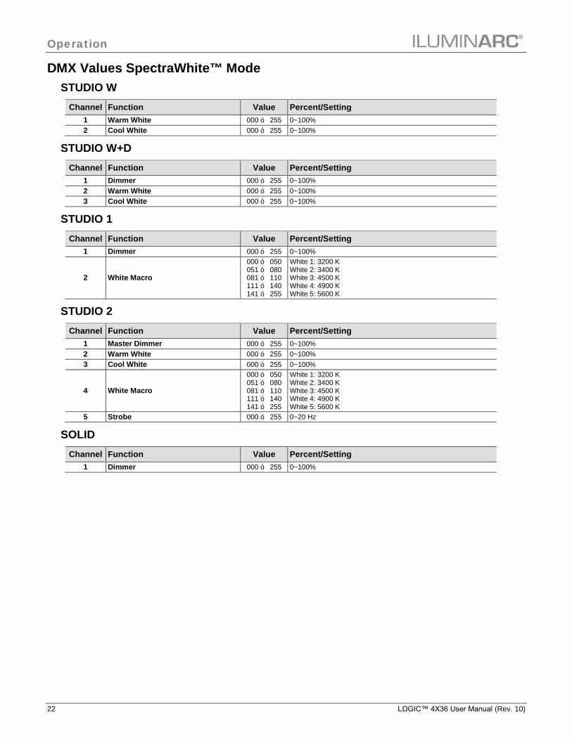
DMX Values SpectraWhite™ Mode STUDIO W
Channel Function Value Percent/Setting 1 Warm White 000 ó 255 0~100% 2 Cool White 000 ó 255 0~100%
STUDIO W+D Channel Function Value Percent/Setting
1 Dimmer 000 ó 255 0~100% 2 Warm White 000 ó 255 0~100% 3 Cool White 000 ó 255 0~100%
STUDIO 1 Channel Function Value Percent/Setting
1 Dimmer 000 ó 255 0~100%
2 White Macro
000 ó 050 051 ó 080 081 ó 110 111 ó 140 141 ó 255
White 1: 3200 K White 2: 3400 K White 3: 4500 K White 4: 4900 K White 5: 5600 K
STUDIO 2 Channel Function Value Percent/Setting
1 Master Dimmer 000 ó 255 0~100% 2 Warm White 000 ó 255 0~100% 3 Cool White 000 ó 255 0~100%
4 White Macro
000 ó 050 051 ó 080 081 ó 110 111 ó 140 141 ó 255
White 1: 3200 K White 2: 3400 K White 3: 4500 K White 4: 4900 K White 5: 5600 K
5 Strobe 000 ó 255 0~20 Hz
SOLID Channel Function Value Percent/Setting
1 Dimmer 000 ó 255 0~100%
Technical Information
LΩGIC™ 4X36 User Manual (Rev. 10) 23
5. Technical Information
If the product has fans, make sure that you
never spin a fan if cleaning the product with compressed air.
Always dry the external optics and glass surfaces carefully
after cleaning them.
If you still experience technical problems after
trying the solutions in the Troubleshooting Table, contact ILUMINARC® Technical Support.
System Maintenance To maintain optimum performance and minimize wear, the user should clean the product frequently. Usage and environment are contributing factors in determining the cleaning frequency. As a rule, the user should clean the product at least twice a month. Dust build up reduces light output performance and can cause overheating. This can lead to reduced light source life and increased mechanical wear. The cleaning frequency depends on the environment in which the product operates. Damp, smoky, or particularly dirty surrounding can cause greater accumulation of dirt on the product’s optics. To clean a product, follow the recommendations below: 1. Unplug the product from power. 2. Wait until the product is cold. 3. Use a vacuum (or dry compressed air) and a soft brush to remove dust collected on the
external vents and reachable internal components. 4. Apply the solution directly to the cloth or tissue and drag any dirt and grime to the
outside of the product.
Product Repairs ILUMINARC® strongly advises you against attempting any repairs to this product unless you are an authorized ILUMINARC® technician. ILUMINARC® presents the information contained in the Troubleshooting Table as a guide only. In most cases, opening the product’s housing will invalidate its warranty, unless there is a written indication to the contrary.
Technical Information
24 LΩGIC™ 4X36 User Manual (Rev. 10)
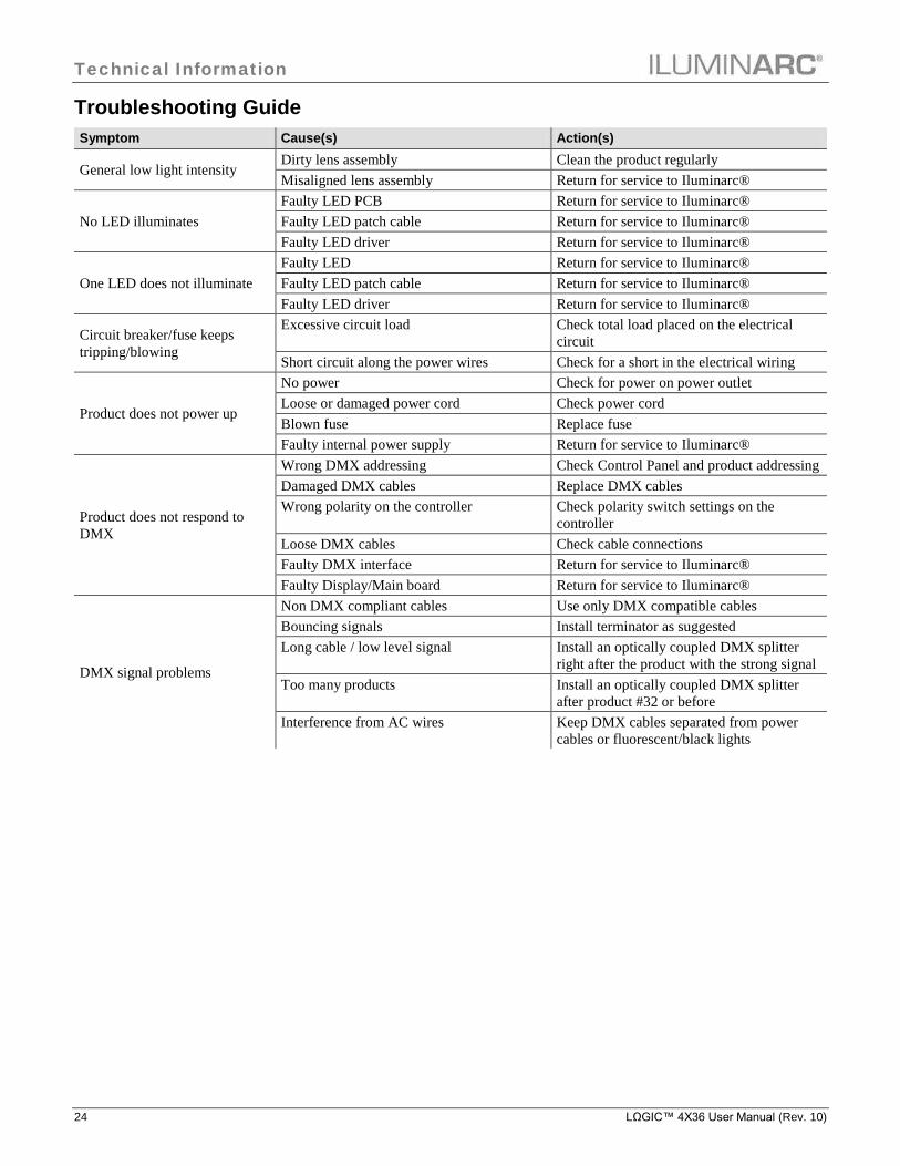
Troubleshooting Guide Symptom Cause(s) Action(s)
General low light intensity Dirty lens assembly Clean the product regularly Misaligned lens assembly Return for service to Iluminarc®
No LED illuminates Faulty LED PCB Return for service to Iluminarc® Faulty LED patch cable Return for service to Iluminarc® Faulty LED driver Return for service to Iluminarc®
One LED does not illuminate Faulty LED Return for service to Iluminarc® Faulty LED patch cable Return for service to Iluminarc® Faulty LED driver Return for service to Iluminarc®
Circuit breaker/fuse keeps tripping/blowing
Excessive circuit load Check total load placed on the electrical circuit
Short circuit along the power wires Check for a short in the electrical wiring
Product does not power up
No power Check for power on power outlet Loose or damaged power cord Check power cord Blown fuse Replace fuse Faulty internal power supply Return for service to Iluminarc®
Product does not respond to DMX
Wrong DMX addressing Check Control Panel and product addressing Damaged DMX cables Replace DMX cables Wrong polarity on the controller Check polarity switch settings on the
controller Loose DMX cables Check cable connections Faulty DMX interface Return for service to Iluminarc® Faulty Display/Main board Return for service to Iluminarc®
DMX signal problems
Non DMX compliant cables Use only DMX compatible cables Bouncing signals Install terminator as suggested Long cable / low level signal Install an optically coupled DMX splitter
right after the product with the strong signal Too many products Install an optically coupled DMX splitter
after product #32 or before Interference from AC wires Keep DMX cables separated from power
cables or fluorescent/black lights

Technical Information
LΩGIC™ 4X36 User Manual (Rev. 10) 25
LED Disclaimer LED Life ILUMINARC® rates LED lifetime based on lumen depreciation of 70% of the original output, with data provided by the manufacturer of the LED. Data from the manufacturer of the LED are not independently verified or measured by ILUMINARC®. When the product is operating in optimal environmental conditions, the LED lifetime is rated to be 50,000 to 70,000 hours by the LED manufacturer.
LED Binning LED manufacturers sort LEDs into “bins”, based on variances in color, output intensity and the frequency at which the semiconductor operates. ILUMINARC® strives to hold its LED manufacturers to the highest standards of binning to optimize consistency in output from product to product. However, the availability of a single bin cannot be guaranteed. With that in mind, ILUMINARC® has developed a rigorous control system to seek the best achievable consistency in color and output.
Color Rendering Index (CRI) CRI is an industry standard method to compare properties of different types of light sources. There are known limitations and inconsistencies related to CRI. Results may vary depending on the environmental factors involved. For this reason, the US Department of Energy (DOE) states that CRI should be considered as one point of reference among others in evaluating white LED products and systems. The following is an excerpt of recommendations from the DOE: 1. Identify the visual tasks to be performed under the light source. If color fidelity under
different light sources is critically important (for example, in a space where color or fabric comparisons are made under both daylight and electric lighting), CRI values may be a useful metric for rating LED products.
2. CRI may be compared only for light sources of equal CCT. This applies to all light sources, not only to LEDs. Also, differences in CRI values of less than five points are not significant, e.g., light sources with 80 and 84 CRI are essentially the same.
3. If color appearance is more important than color fidelity, do not exclude white light LEDs solely on the basis of relatively low CRI values. Some LED products with CRIs as low as 25 still produce visually pleasing white light.
4. Evaluate LED systems in person and, if possible, on-site when color fidelity or color appearance are important issues.
Source: DOE publication: PNNL-SA-56891, January 2008

Technical Information
26 LΩGIC™ 4X36 User Manual (Rev. 10)
DO NOT write the RMA # directly on the box. Instead,
write it on a properly affixed label.
ILUMINARC® reserves the right to use its own discretion to
repair or replace returned product(s).
Always keep the original box and all packaging material as you
will need those to ship the product back to ILUMINARC®.
Returns Procedure The user must send the merchandise prepaid, in the original box, and with its original packing and accessories. ILUMINARC® will not issue call tags. Call ILUMINARC® and request a Return Merchandise Authorization Number (RMA #) before shipping the product. Be prepared to provide the model number, serial number, and a brief description of the cause for the return. The user must clearly label the package with a Return Merchandise Authorization Number (RMA #). ILUMINARC® will refuse any product returned without a RMA #. Once you receive the RMA #, please include the following information on a piece of paper inside the box:
· Your name · Your address · Your phone number · The RMA # · A brief description of the problem
Be sure to pack the product properly. Any shipping damage resulting from inadequate packaging will be the customer’s responsibility. As a suggestion, proper FedEx packing or double-boxing is the shipping method ILUMINARC® recommends.
Claims The carrier is responsible for any damage incurred during shipping. Therefore, if the received merchandise appears to have damages caused during shipping, the customer must submit the damage report and any related claims with the carrier, not ILUMINARC®. The customer must submit the report upon reception of the damaged merchandise. Failure to do so in a timely manner may invalidate the customer’s claim with the carrier. For other issues such as missing components or parts, damage not related to shipping, or concealed damage, the customer must make claims to ILUMINARC® within seven (7) days of receiving the merchandise.
Contact Us World Wide
General Information ILUMINARC® 5200 NW 108th Avenue Sunrise, FL 33351
Voice: (954) 923-3680 Fax: (954) 929-5571 Email: [email protected]
Customer Support Voice: (954) 923-3680 (ext. 4000) Fax: (954) 756-8015
Email: [email protected] World Wide Web www.iluminarc.com
Technical Information
LΩGIC™ 4X36 User Manual (Rev. 10) 27
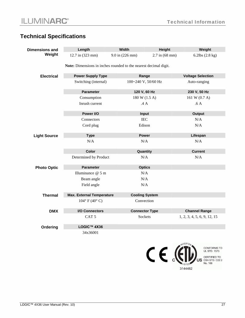
Technical Specifications
Dimensions and Weight
Length Width Height Weight 12.7 in (323 mm) 9.0 in (226 mm) 2.7 in (68 mm) 6.2lbs (2.8 kg)
Note: Dimensions in inches rounded to the nearest decimal digit.
Electrical Power Supply Type Range Voltage Selection Switching (internal) 100~240 V, 50/60 Hz Auto-ranging Parameter 120 V, 60 Hz 230 V, 50 Hz Consumption 180 W (1.5 A) 161 W (0.7 A) Inrush current .4 A .6 A
Power I/O Input Output Connectors IEC N/A Cord plug Edison N/A
Light Source Type Power Lifespan N/A N/A N/A
Color Quantity Current Determined by Product N/A N/A
Photo Optic Parameter Optics Illuminance @ 5 m N/A Beam angle N/A Field angle N/A
Thermal Max. External Temperature Cooling System
104° F (40° C) Convection
DMX I/O Connectors Connector Type Channel Range CAT 5 Sockets 1, 2, 3, 4, 5, 6, 9, 12, 15
Ordering LΩGIC™ 4X36
34x36001

ILUMINARC® 5200 NW 108th Avenue Sunrise, FL 33351 U.S.A. Tel.: (954) 923-3680 www.iluminarc.com LΩGIC™ 4X36 User Manual Rev. 8 May 2013