Embed Size (px)
Citation preview
Logging servicesProduct catalogue
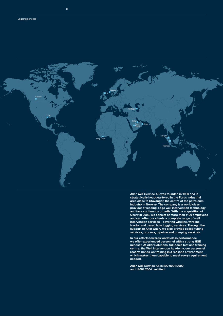
Aker Well Service AS was founded in 1980 and is strategically headquartered in the Forus industrial area close to Stavanger, the centre of the petroleum industry in Norway. The company is a world class provider of leading-edge well intervention technology and face continuous growth. With the acquisition of Qserv in 2008, we consist of more than 1100 employees and can offer our clients a complete range of well intervention services – covering wireline, wireline tractor and cased hole logging services. Through the support of Aker Qserv we also provide coiled tubing services, process, pipeline and pumping services.
In our efforts towards world class performance we offer experienced personnel with a strong HSE mindset. At Aker Solutions’ full-scale test and training centre, the Well Intervention Academy, our personnel receive hands-on training in a realistic environment which makes them capable to meet every requirement needed.
Aker Well Service AS is ISO 9001:2000 and 14001:2004 certified.
Logging services
2
Logging services
Contents
Production logging 5 Standard toolstrings 6 Production logging analysis 8 Downhole controller, XTU 10 Ultrawire™ memory tool, UMT 11 Quartz pressure and CCL, QPC 12 Production gamma ray, PGR 13 Capacitance temperature flow, CTF 14 Fluid density radioactive, FDR 15 X-Y Production dual caliper, PDC 16 Fullbore spinners, CFB and CFM 17 Inline spinner, ILS 18 PL in horizontal wells, CAT and RAT 19Well integrity logging 21 Multifinger imaging tool, MIT 24 Magnetic thickness tool, MTT 27 Multifinger caliper and MTT analysis 28Electronic memory gauges 29Correlation, plug setting, explosive services 31
3
Aker Well Service AS is a well-reputed provider of cased hole logging and explosive services. We offer an extensive range of services, including production logging, well integrity logging, correlation, plug setting and explosive services, in addition to high quality data analysis.
The production logging and well integrity tools are supplied by GE Oilfield Technology (previously Sondex). Logging software utilized is Warrior (delivered by Scientific Data Systems) with MIPS (from Epidote) software used for Well Integrity analysis and Kappa’s Emeraude for PLT analysis.
Our logging equipment comply with the NORSOK standards.
Production logging
4
Production logging
Production logging
5
Swift and accurate production measurements within producing oil and gas wells are crucial in order to optimize production and to ensure the most cost-effective hydrocarbon abstraction. The objective of production logging (PL) is to provide the client with data enabling them to maximize oil or gas recovery from their reservoirs.
Production logging
PLT
MemoryPLT
6
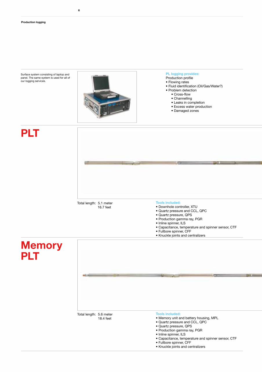
Total length: 5.1 meter 16.7 feet
Total length: 5.6 meter 18.4 feet
Tools included: • Downhole controller, XTU• Quartz pressure and CCL, QPC• Quartz pressure, QPS• Production gamma ray, PGR• Inline spinner, ILS• Capacitance, temperature and spinner sensor, CTF• Fullbore spinner, CFF• Knuckle joints and centralizers
Tools included: • Memory unit and battery housing, MPL• Quartz pressure and CCL, QPC• Quartz pressure, QPS• Production gamma ray, PGR• Inline spinner, ILS• Capacitance, temperature and spinner sensor, CTF• Fullbore spinner, CFF• Knuckle joints and centralizers
Surface system consisting of laptop and panel. The same system is used for all of our logging services.
PL logging provides: Production profile• Flowing rates• Fluid identification (Oil/Gas/Water?)• Problem detection • Cross-flow • Channelling • Leaks in completion • Excess water production • Damaged zones
Logging services
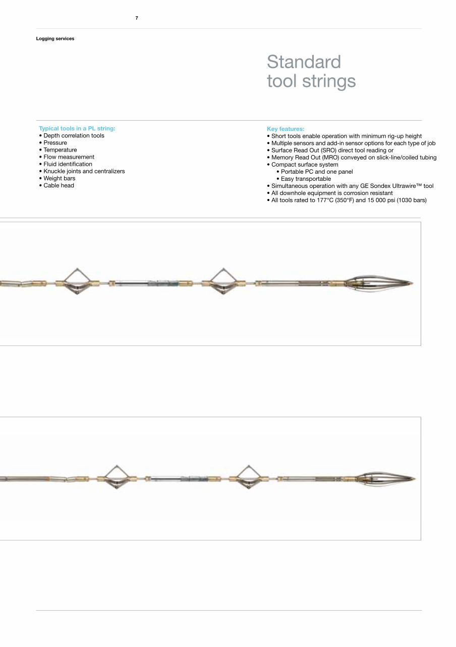
Key features:• Short tools enable operation with minimum rig-up height• Multiple sensors and add-in sensor options for each type of job• Surface Read Out (SRO) direct tool reading or• Memory Read Out (MRO) conveyed on slick-line/coiled tubing• Compact surface system • Portable PC and one panel • Easy transportable • Simultaneous operation with any GE Sondex Ultrawire™ tool• All downhole equipment is corrosion resistant• All tools rated to 177°C (350°F) and 15 000 psi (1030 bars)
7
Standard tool strings
PL logging provides: Production profile• Flowing rates• Fluid identification (Oil/Gas/Water?)• Problem detection • Cross-flow • Channelling • Leaks in completion • Excess water production • Damaged zones
Typical tools in a PL string:• Depth correlation tools • Pressure• Temperature• Flow measurement• Fluid identification• Knuckle joints and centralizers• Weight bars• Cable head
Production logging
8
Production logging and its interpretation has changed dramatically over the past 20 years due to the advances in electronics, sensors, and computer technology. It is now seen as a powerful quantitative method that takes its own place in the set of data acquisition tools for the reservoir engineer alongside pressure transient and production decline analysis.
In near vertical and homogeneous flow regimes Aker Well Service deploys our standard PLT toolstrings; usually incorporating both full-bore and inline spinners, pressure, temperature, capacitance and density tools (in addition to the gamma-ray and CCL used for depth correlation). In situations where stratified flow is expected (particularly highly deviated wells) we supplement these options with our GE Sondex array tools; collectively called the “MAPS” system.
Aker Well Service utilizes Kappa’s Emeraude for the analysis/interpretation of all of our PLT data allowing the customer to benefit from both the very best in computa-tional models alongside intuitive means for display/ interrogation of the results. Rate calculation is treated as a minimization problem and solved using nonlinear regression, offering full flexibility in the type and number of input measurements. Emeraude includes specific treatment for the GE Sondex “MAPS” tools: the Capaci-tance Array Tool (CAT) and the Resistance Array Tool (RAT); image tracks can be created, and cross sections displayed at any depth.
Production logging analysis
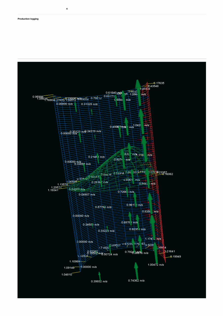
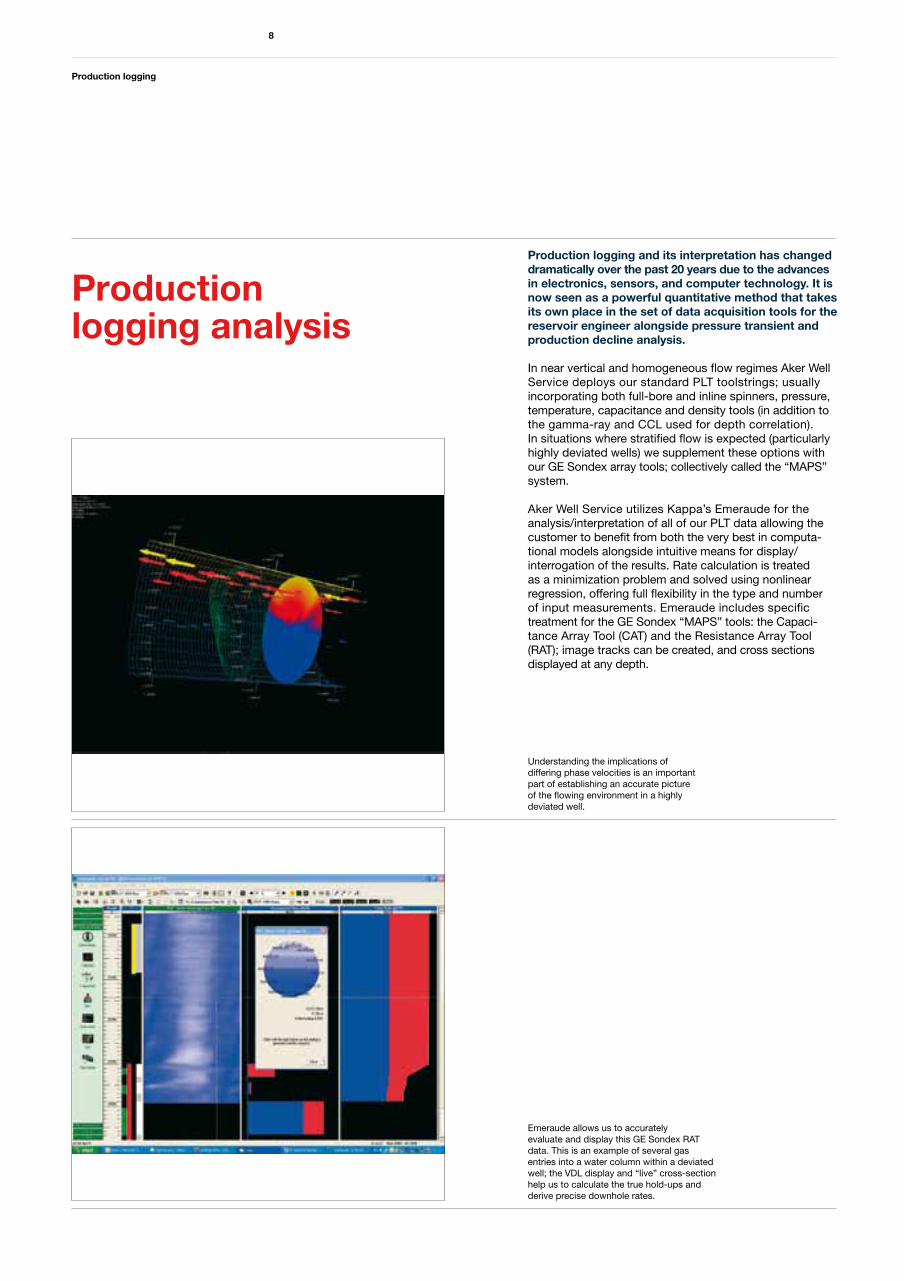
Understanding the implications of differing phase velocities is an important part of establishing an accurate picture of the flowing environment in a highly deviated well.
Emeraude allows us to accurately evaluate and display this GE Sondex RAT data. This is an example of several gas entries into a water column within a deviated well; the VDL display and “live” cross-section help us to calculate the true hold-ups and derive precise downhole rates.
Production logging
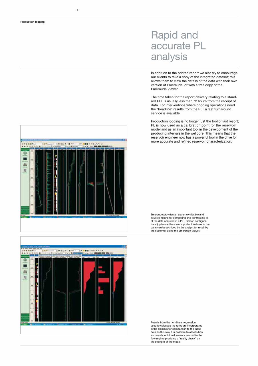
In addition to the printed report we also try to encourage our clients to take a copy of the integrated dataset; this allows them to view the details of the data with their own version of Emeraude, or with a free copy of the Emeraude Viewer.
The time taken for the report delivery relating to a stand-ard PLT is usually less than 72 hours from the receipt of data. For interventions where ongoing operations need the “headline” results from the PLT a fast turnaround service is available.
Production logging is no longer just the tool of last resort; PL is now used as a calibration point for the reservoir model and as an important tool in the development of the producing intervals in the wellbore. This means that the reservoir engineer now has a powerful tool in the drive for more accurate and refined reservoir characterization.
9
Rapid andaccurate PLanalysis
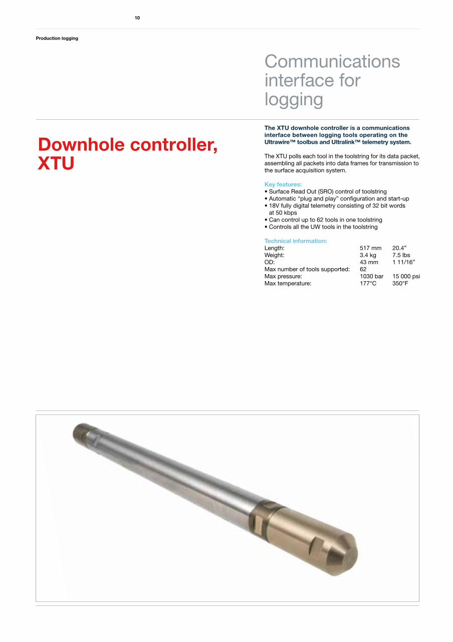
Emeraude provides an extremely flexible and intuitive means for comparing and contrasting all of the data acquired in a PLT. Screen configura-tions (optimised to show important features in the data) can be archived by the analyst for recall by the customer using the Emeraude Viewer.
Results from the non-linear regression used to calculate the rates are incorporated in the displays for comparison to the input data. In this way it is possible to assess how accurately individual sensors reacted to the flow regime providing a “reality check” on the strength of the model.
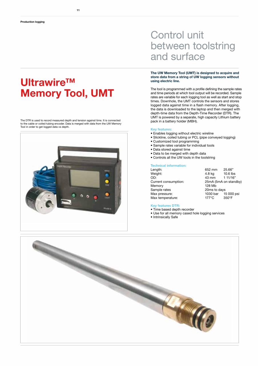
The XTU downhole controller is a communications interface between logging tools operating on the Ultrawire™ toolbus and Ultralink™ telemetry system.
The XTU polls each tool in the toolstring for its data packet, assembling all packets into data frames for transmission to the surface acquisition system.
Key features:• Surface Read Out (SRO) control of toolstring• Automatic “plug and play” configuration and start-up• 18V fully digital telemetry consisting of 32 bit words at 50 kbps• Can control up to 62 tools in one toolstring• Controls all the UW tools in the toolstring
Technical information:Length: 517 mm 20.4”Weight: 3.4 kg 7.5 lbsOD: 43 mm 1 11/16”Max number of tools supported: 62Max pressure: 1030 bar 15 000 psi Max temperature: 177°C 350°F
Production logging
10
Communicationsinterface for logging
Downhole controller,XTU
Production logging
11
Control unit between toolstring and surface
Ultrawire™ Memory Tool, UMT
The DTR is used to record measured depth and tension against time. It is connectedto the cable or coiled tubing encoder. Data is merged with data from the UW Memory Tool in order to get logged data vs depth.
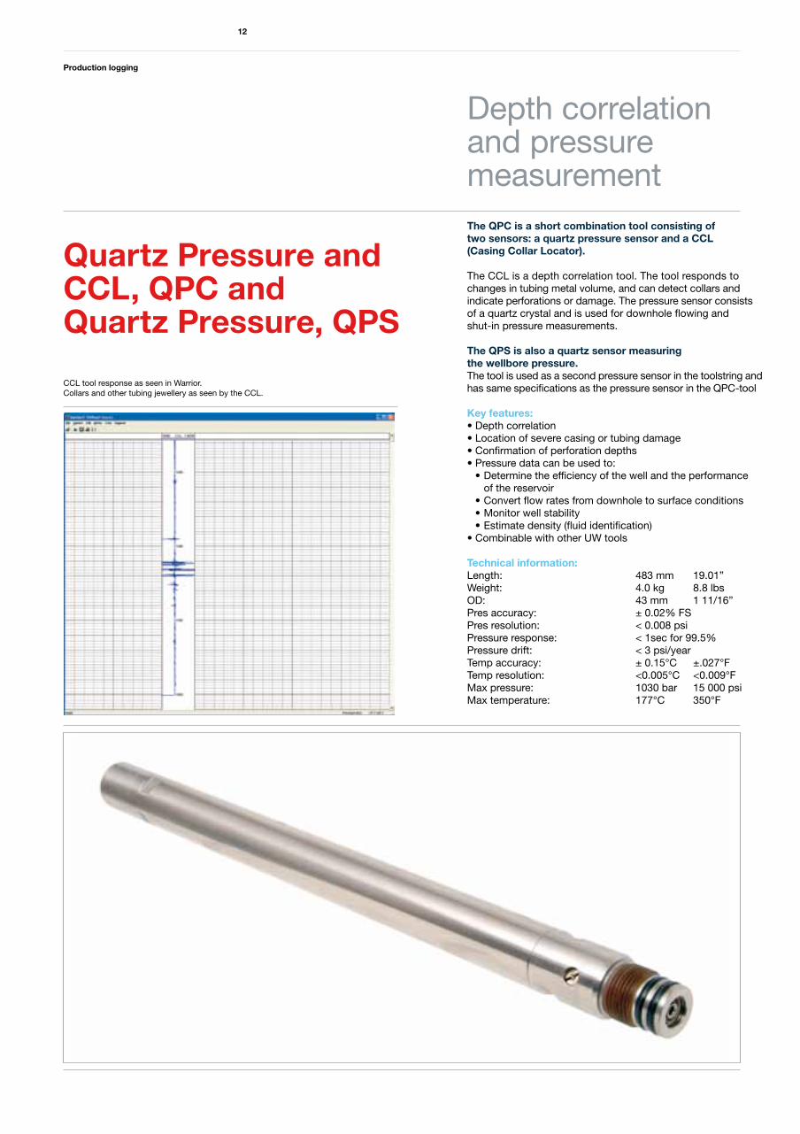
The UW Memory Tool (UMT) is designed to acquire and store data from a string of UW logging sensors without using electric line.
The tool is programmed with a profile defining the sample rates and time periods at which tool output will be recorded. Sample rates are variable for each logging tool as well as start and stop times. Downhole, the UMT controls the sensors and stores logged data against time in a flash memory. After logging, the data is downloaded to the laptop and then merged with depth-time data from the Depth-Time Recorder (DTR). The UMT is powered by a separate, high capacity Lithium battery pack in a battery holder (MBH).
Key features:• Enables logging without electric wireline• Slickline, coiled tubing or PCL (pipe conveyed logging)• Customized tool programming• Sample rates variable for individual tools• Data stored against time• Data to be merged with depth data• Controls all the UW tools in the toolstring
Technical information:Length: 652 mm 25.66”Weight: 4.8 kg 10.6 lbsOD: 43 mm 1 11/16”Current consumption: 25mA (5mA on standby)Memory 128 MbSample rates 20ms to daysMax pressure: 1030 bar 15 000 psiMax temperature: 177°C 350°F
Key features DTR:• Time based depth recorder• Use for all memory cased hole logging services• Intrinsically Safe
The QPC is a short combination tool consisting oftwo sensors: a quartz pressure sensor and a CCL (Casing Collar Locator).
The CCL is a depth correlation tool. The tool responds to changes in tubing metal volume, and can detect collars and indicate perforations or damage. The pressure sensor consists of a quartz crystal and is used for downhole flowing and shut-in pressure measurements.
The QPS is also a quartz sensor measuring the wellbore pressure. The tool is used as a second pressure sensor in the toolstring and has same specifications as the pressure sensor in the QPC-tool
Key features:• Depth correlation• Location of severe casing or tubing damage• Confirmation of perforation depths• Pressure data can be used to: • Determine the efficiency of the well and the performance of the reservoir • Convert flow rates from downhole to surface conditions • Monitor well stability • Estimate density (fluid identification)• Combinable with other UW tools
Technical information:Length: 483 mm 19.01”Weight: 4.0 kg 8.8 lbsOD: 43 mm 1 11/16”Pres accuracy: ± 0.02% FSPres resolution: < 0.008 psiPressure response: < 1sec for 99.5%Pressure drift: < 3 psi/yearTemp accuracy: ± 0.15°C ±.027°FTemp resolution: <0.005°C <0.009°FMax pressure: 1030 bar 15 000 psi Max temperature: 177°C 350°F
Production logging
12
Depth correlationand pressuremeasurement
Quartz Pressure and CCL, QPC and Quartz Pressure, QPS
CCL tool response as seen in Warrior. Collars and other tubing jewellery as seen by the CCL.
Production logging
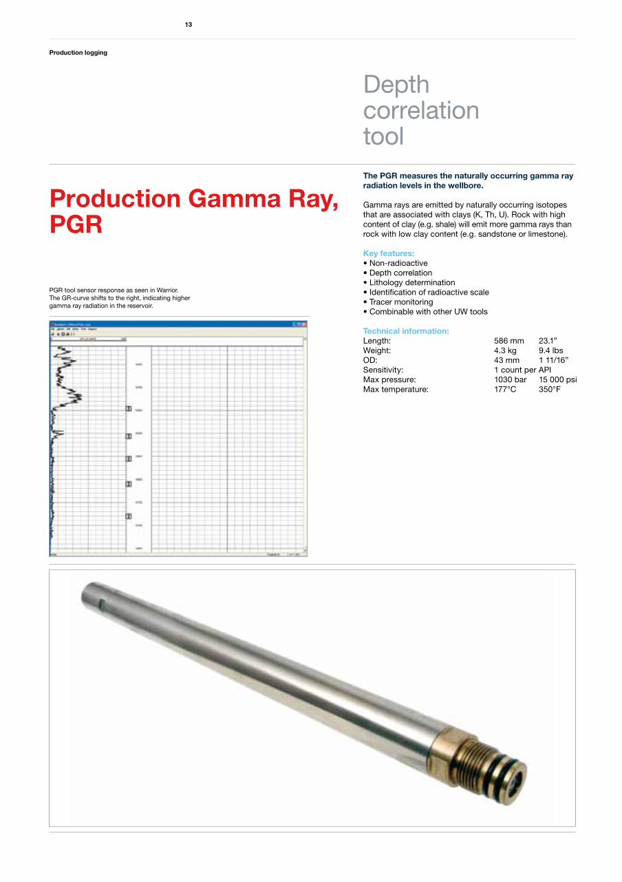
The PGR measures the naturally occurring gamma ray radiation levels in the wellbore.
Gamma rays are emitted by naturally occurring isotopes that are associated with clays (K, Th, U). Rock with high content of clay (e.g. shale) will emit more gamma rays than rock with low clay content (e.g. sandstone or limestone).
Key features:• Non-radioactive• Depth correlation• Lithology determination• Identification of radioactive scale• Tracer monitoring• Combinable with other UW tools
Technical information:Length: 586 mm 23.1”Weight: 4.3 kg 9.4 lbsOD: 43 mm 1 11/16”Sensitivity: 1 count per APIMax pressure: 1030 bar 15 000 psi Max temperature: 177°C 350°F
13
Depth correlationtool
Production Gamma Ray,PGR
PGR tool sensor response as seen in Warrior.The GR-curve shifts to the right, indicating higher gamma ray radiation in the reservoir.
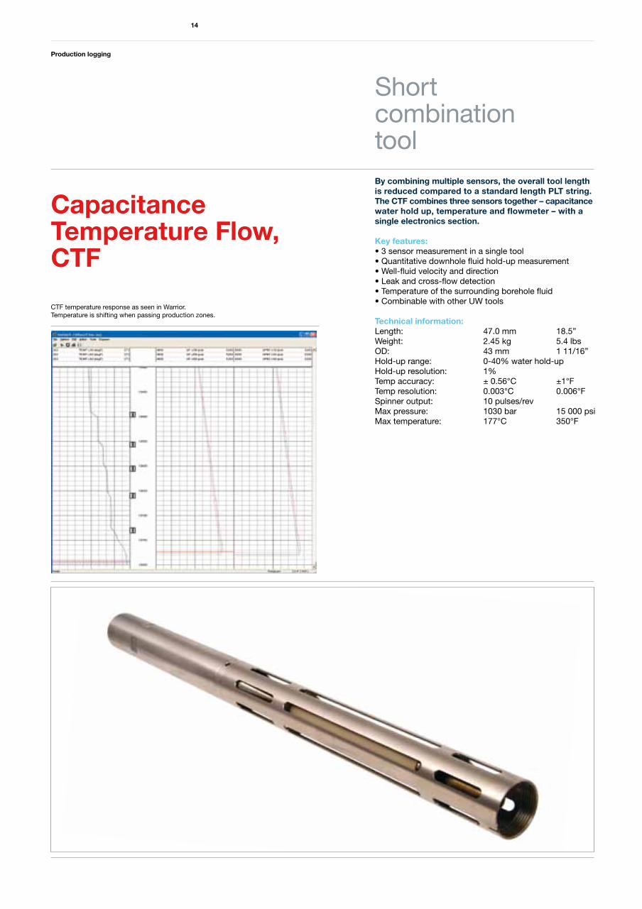
By combining multiple sensors, the overall tool length is reduced compared to a standard length PLT string. The CTF combines three sensors together – capacitance water hold up, temperature and flowmeter – with a single electronics section.
Key features:• 3 sensor measurement in a single tool• Quantitative downhole fluid hold-up measurement• Well-fluid velocity and direction• Leak and cross-flow detection• Temperature of the surrounding borehole fluid• Combinable with other UW tools
Technical information:Length: 47.0 mm 18.5”Weight: 2.45 kg 5.4 lbsOD: 43 mm 1 11/16”Hold-up range: 0-40% water hold-upHold-up resolution: 1%Temp accuracy: ± 0.56°C ±1°FTemp resolution: 0.003°C 0.006°FSpinner output: 10 pulses/revMax pressure: 1030 bar 15 000 psi Max temperature: 177°C 350°F
Production logging
14
Short combinationtool
Capacitance Temperature Flow,CTF
CTF temperature response as seen in Warrior. Temperature is shifting when passing production zones.
Production logging
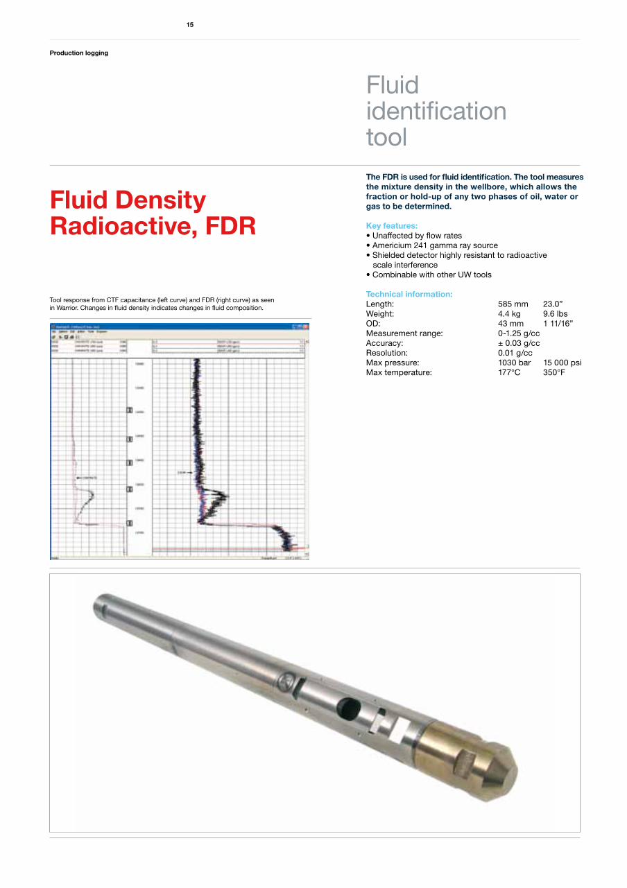
The FDR is used for fluid identification. The tool measures the mixture density in the wellbore, which allows the fraction or hold-up of any two phases of oil, water or gas to be determined.
Key features:• Unaffected by flow rates• Americium 241 gamma ray source• Shielded detector highly resistant to radioactive scale interference• Combinable with other UW tools
Technical information:Length: 585 mm 23.0”Weight: 4.4 kg 9.6 lbsOD: 43 mm 1 11/16”Measurement range: 0-1.25 g/ccAccuracy: ± 0.03 g/ccResolution: 0.01 g/ccMax pressure: 1030 bar 15 000 psi Max temperature: 177°C 350°F
15
Fluid identificationtool
Fluid Density Radioactive, FDR
Tool response from CTF capacitance (left curve) and FDR (right curve) as seen in Warrior. Changes in fluid density indicates changes in fluid composition.
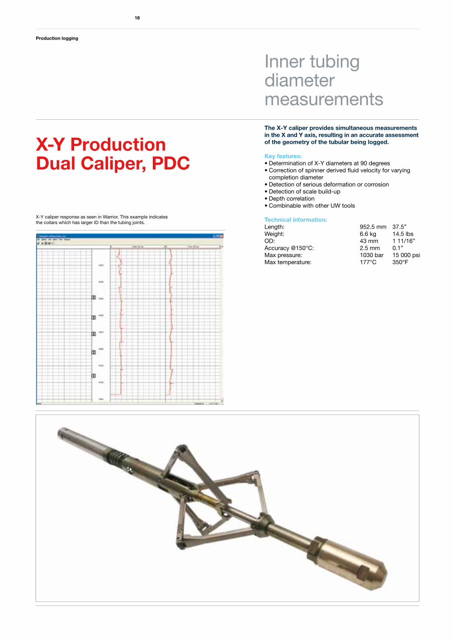
The X-Y caliper provides simultaneous measurements in the X and Y axis, resulting in an accurate assessment of the geometry of the tubular being logged.
Key features:• Determination of X-Y diameters at 90 degrees• Correction of spinner derived fluid velocity for varying completion diameter• Detection of serious deformation or corrosion• Detection of scale build-up• Depth correlation• Combinable with other UW tools
Technical information:Length: 952.5 mm 37.5”Weight: 6.6 kg 14.5 lbsOD: 43 mm 1 11/16”Accuracy @150°C: 2.5 mm 0.1”Max pressure: 1030 bar 15 000 psiMax temperature: 177°C 350°F
Production logging
16
Inner tubingdiametermeasurements
X-Y Production Dual Caliper, PDC
X-Y caliper response as seen in Warrior. This example indicates the collars which has larger ID than the tubing joints.
Production logging
17
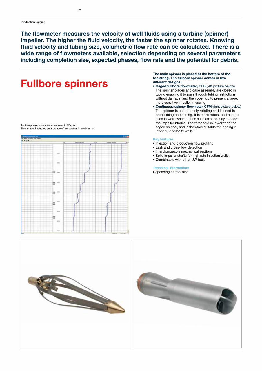
The flowmeter measures the velocity of well fluids using a turbine (spinner) impeller. The higher the fluid velocity, the faster the spinner rotates. Knowing fluid velocity and tubing size, volumetric flow rate can be calculated. There is a wide range of flowmeters available, selection depending on several parameters including completion size, expected phases, flow rate and the potential for debris.
Fullbore spinnersThe main spinner is placed at the bottom of thetoolstring. The fullbore spinner comes in two different designs: •Cagedfullboreflowmeter,CFB(left picture below) The spinner blades and cage assembly are closed in tubing enabling it to pass through tubing restrictions without damage, and then open up to present a large, more sensitive impeller in casing•Continuousspinnerflowmeter,CFM(right picture below) The spinner is continuously rotating and is used in both tubing and casing. It is more robust and can be used in wells where debris such as sand may impede the impeller blades. The threshold is lower than the caged spinner, and is therefore suitable for logging in lower fluid velocity wells.
Key features:• Injection and production flow profiling• Leak and cross-flow detection• Interchangeable mechanical sections• Solid impeller shafts for high rate injection wells• Combinable with other UW tools
Technical information:Depending on tool size.
Tool response from spinner as seen in Warrior. This image illustrates an increase of production in each zone.
Production logging
18
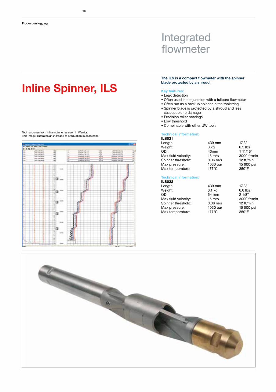
The ILS is a compact flowmeter with the spinner blade protected by a shroud.
Key features:• Leak detection• Often used in conjunction with a fullbore flowmeter• Often run as a backup spinner in the toolstring • Spinner blade is protected by a shroud and less susceptible to damage• Precision roller bearings• Low threshold• Combinable with other UW tools
Technical information:ILS021Length: 439 mm 17.3” Weight: 3 kg 6.5 lbsOD: 43mm 1 11/16”Max fluid velocity: 15 m/s 3000 ft/minSpinner threshold: 0.06 m/s 12 ft/minMax pressure: 1030 bar 15 000 psi Max temperature: 177°C 350°F
Technical information:ILS022Length: 439 mm 17.3” Weight: 3.1 kg 6.8 lbsOD: 54 mm 2 1/8”Max fluid velocity: 15 m/s 3000 ft/minSpinner threshold: 0.06 m/s 12 ft/minMax pressure: 1030 bar 15 000 psi Max temperature: 177°C 350°F
Integrated flowmeter
Inline Spinner, ILS
Tool response from inline spinner as seen in Warrior. This image illustrates an increase of production in each zone.
Production logging
19
Production loggingin horizontal wells
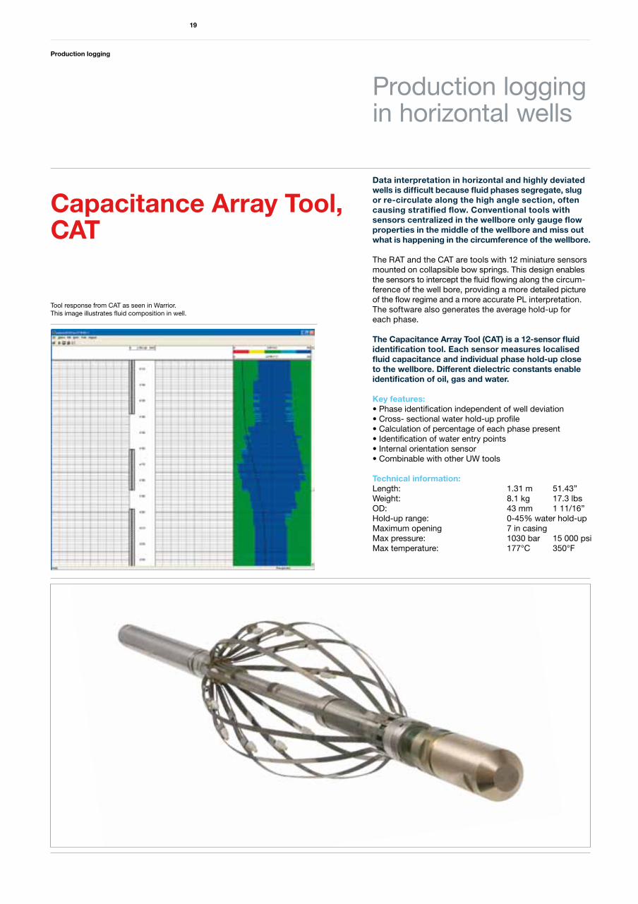
Data interpretation in horizontal and highly deviated wells is difficult because fluid phases segregate, slug or re-circulate along the high angle section, often causing stratified flow. Conventional tools with sensors centralized in the wellbore only gauge flow properties in the middle of the wellbore and miss out what is happening in the circumference of the wellbore.
The RAT and the CAT are tools with 12 miniature sensors mounted on collapsible bow springs. This design enables the sensors to intercept the fluid flowing along the circum-ference of the well bore, providing a more detailed picture of the flow regime and a more accurate PL interpretation. The software also generates the average hold-up for each phase.
The Capacitance Array Tool (CAT) is a 12-sensor fluid identification tool. Each sensor measures localised fluid capacitance and individual phase hold-up close to the wellbore. Different dielectric constants enableidentification of oil, gas and water.
Key features:• Phase identification independent of well deviation• Cross- sectional water hold-up profile• Calculation of percentage of each phase present • Identification of water entry points• Internal orientation sensor• Combinable with other UW tools
Technical information:Length: 1.31 m 51.43”Weight: 8.1 kg 17.3 lbsOD: 43 mm 1 11/16”Hold-up range: 0-45% water hold-upMaximum opening 7 in casingMax pressure: 1030 bar 15 000 psi Max temperature: 177°C 350°F
Capacitance Array Tool, CAT
Tool response from CAT as seen in Warrior.This image illustrates fluid composition in well.
Production logging
20
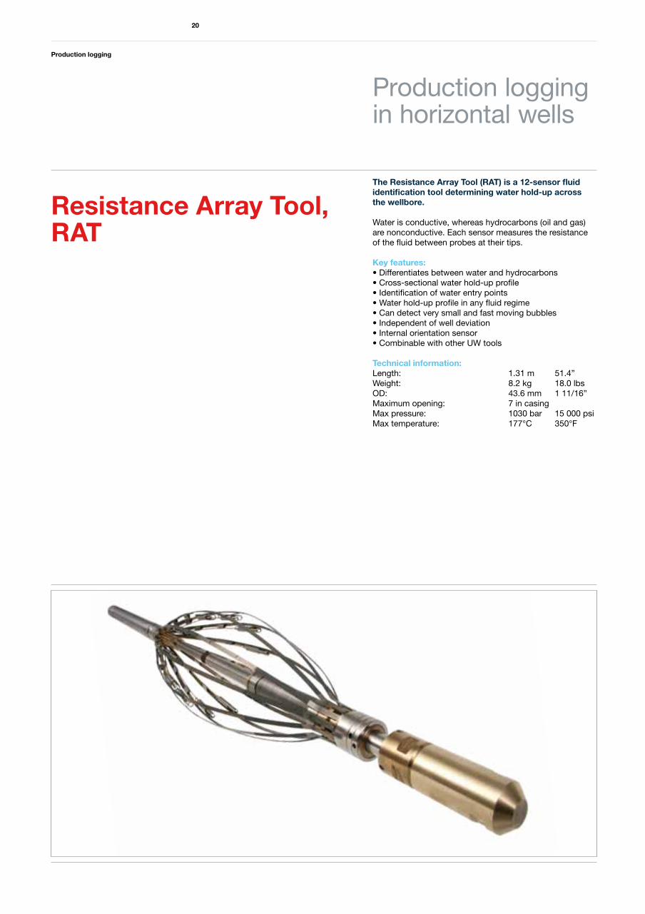
The Resistance Array Tool (RAT) is a 12-sensor fluid identification tool determining water hold-up across the wellbore.
Water is conductive, whereas hydrocarbons (oil and gas) are nonconductive. Each sensor measures the resistance of the fluid between probes at their tips.
Key features:• Differentiates between water and hydrocarbons • Cross-sectional water hold-up profile• Identification of water entry points• Water hold-up profile in any fluid regime• Can detect very small and fast moving bubbles • Independent of well deviation• Internal orientation sensor• Combinable with other UW tools
Technical information:Length: 1.31 m 51.4”Weight: 8.2 kg 18.0 lbsOD: 43.6 mm 1 11/16”Maximum opening: 7 in casingMax pressure: 1030 bar 15 000 psiMax temperature: 177°C 350°F
Production loggingin horizontal wells
Resistance Array Tool, RAT
Production logging
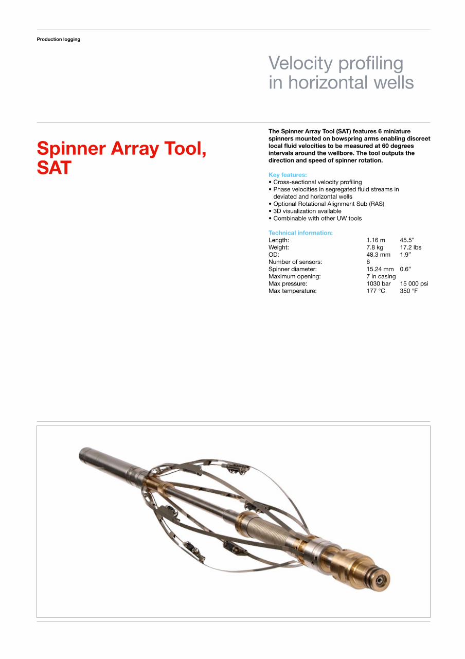
The Spinner Array Tool (SAT) features 6 miniature spinners mounted on bowspring arms enabling discreet local fluid velocities to be measured at 60 degrees intervals around the wellbore. The tool outputs the direction and speed of spinner rotation.
Key features:•Cross-sectionalvelocityprofiling•Phasevelocitiesinsegregatedfluidstreamsin deviatedandhorizontalwells•OptionalRotationalAlignmentSub(RAS)•3Dvisualizationavailable•CombinablewithotherUWtools
Technical information:Length: 1.16m 45.5”Weight: 7.8kg 17.2lbsOD: 48.3mm 1.9”Numberofsensors: 6Spinnerdiameter: 15.24mm 0.6”Maximumopening: 7incasingMaxpressure: 1030bar 15 000psiMaxtemperature: 177°C 350°F
Velocityprofilinginhorizontalwells
Spinner Array Tool, SAT
Well integrity logging
21
Well integrity logging
In the increasingly harsh environments and extended well life that we often encounter in the industry the issue of well integrity is becoming more and more important.
Aker Well Service offers a complete range of GE Sondex electronic calipers alongside the complementary data offered by the Magnetic Thickness Tool (MTT).
MIT
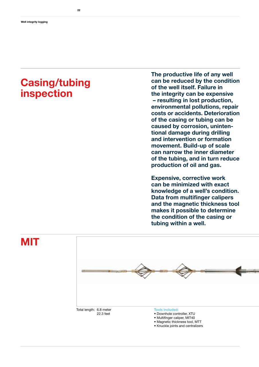
Total length: 6.8 meter 22.3 feet
Tools included: • Downhole controller, XTU• Multifinger caliper, MIT40• Magnetic thickness tool, MTT• Knuckle joints and centralizers
Well integrity logging
22
The productive life of any well can be reduced by the condition of the well itself. Failure in the integrity can be expensive – resulting in lost production, environmental pollutions, repair costs or accidents. Deterioration of the casing or tubing can be caused by corrosion, uninten-tional damage during drilling and intervention or formation movement. Build-up of scale can narrow the inner diameter of the tubing, and in turn reduce production of oil and gas.
Expensive, corrective work can be minimized with exact knowledge of a well’s condition. Data from multifinger calipers and the magnetic thickness tool makes it possible to determine the condition of the casing or tubing within a well.
Casing/tubinginspection
Well integrity logging
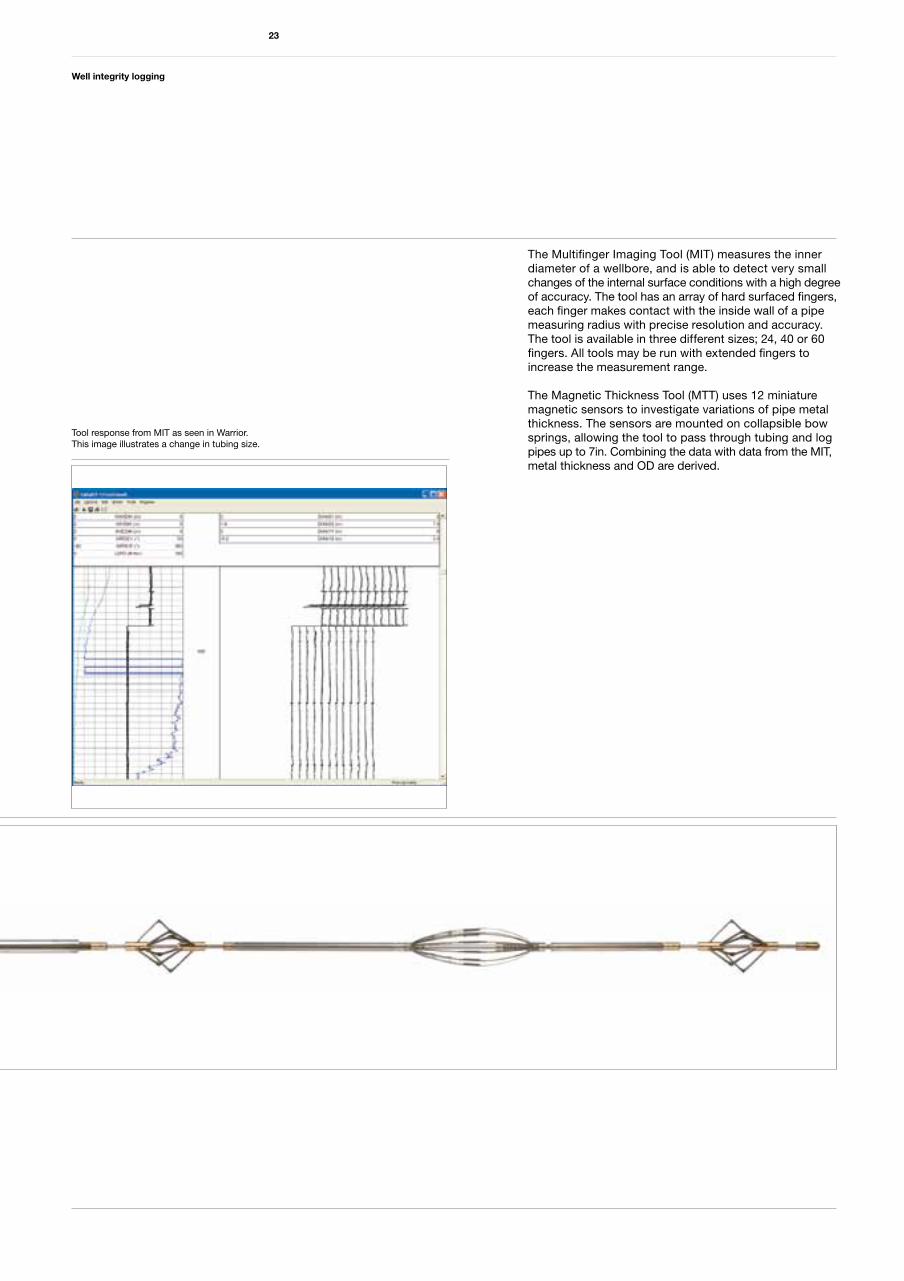
The Multifinger Imaging Tool (MIT) measures the inner diameter of a wellbore, and is able to detect very small changes of the internal surface conditions with a high degree of accuracy. The tool has an array of hard surfaced fingers, each finger makes contact with the inside wall of a pipe measuring radius with precise resolution and accuracy. The tool is available in three different sizes; 24, 40 or 60 fingers. All tools may be run with extended fingers to increase the measurement range.
The Magnetic Thickness Tool (MTT) uses 12 miniature magnetic sensors to investigate variations of pipe metal thickness. The sensors are mounted on collapsible bow springs, allowing the tool to pass through tubing and log pipes up to 7in. Combining the data with data from the MIT, metal thickness and OD are derived.
23
Tool response from MIT as seen in Warrior. This image illustrates a change in tubing size.
Well integrity logging
24
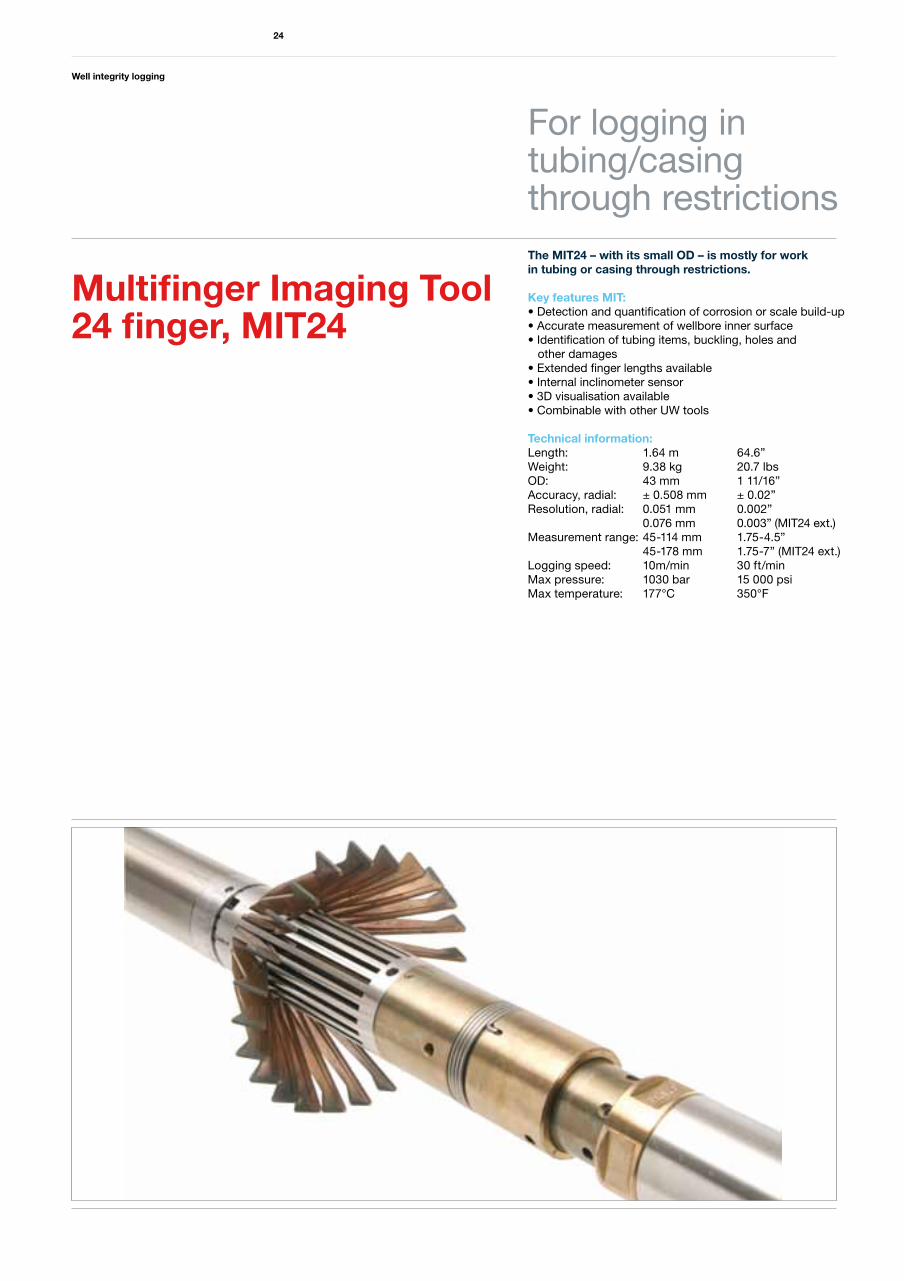
The MIT24 – with its small OD – is mostly for work in tubing or casing through restrictions.
Key features MIT:• Detection and quantification of corrosion or scale build-up• Accurate measurement of wellbore inner surface • Identification of tubing items, buckling, holes and other damages• Extended finger lengths available• Internal inclinometer sensor• 3D visualisation available• Combinable with other UW tools
Technical information:Length: 1.64 m 64.6”Weight: 9.38 kg 20.7 lbsOD: 43 mm 1 11/16”Accuracy, radial: ± 0.508 mm ± 0.02”Resolution, radial: 0.051 mm 0.002” 0.076 mm 0.003” (MIT24 ext.)Measurement range: 45-114 mm 1.75-4.5” 45-178 mm 1.75-7” (MIT24 ext.)Logging speed: 10m/min 30 ft/min Max pressure: 1030 bar 15 000 psi Max temperature: 177°C 350°F
For logging in tubing/casing through restrictions
Multifinger Imaging Tool 24 finger, MIT24
Well integrity logging
25
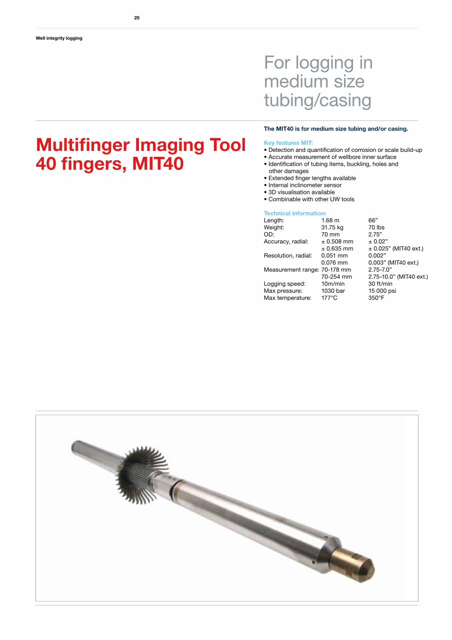
The MIT40 is for medium size tubing and/or casing.
Key features MIT:• Detection and quantification of corrosion or scale build-up• Accurate measurement of wellbore inner surface • Identification of tubing items, buckling, holes and other damages• Extended finger lengths available• Internal inclinometer sensor• 3D visualisation available• Combinable with other UW tools
Technical information:Length: 1.68 m 66”Weight: 31.75 kg 70 lbsOD: 70 mm 2.75”Accuracy, radial: ± 0.508 mm ± 0.02” ± 0.635 mm ± 0.025” (MIT40 ext.) Resolution, radial: 0.051 mm 0.002” 0.076 mm 0.003” (MIT40 ext.)Measurement range: 70-178 mm 2.75-7.0” 70-254 mm 2.75-10.0” (MIT40 ext.)Logging speed: 10m/min 30 ft/min Max pressure: 1030 bar 15 000 psi Max temperature: 177°C 350°F
For logging inmedium size tubing/casing
Multifinger Imaging Tool 40 fingers, MIT40
Well integrity logging
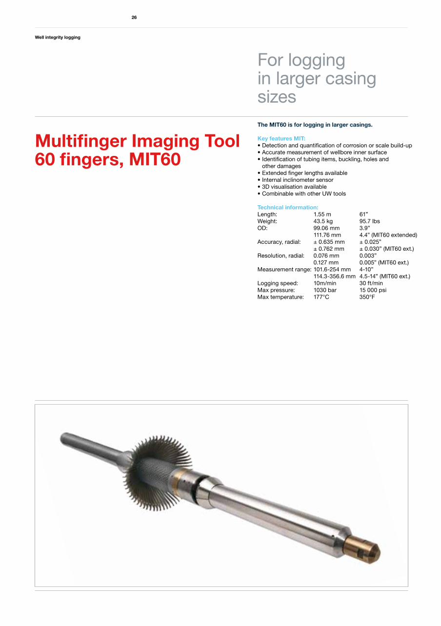
The MIT60 is for logging in larger casings.
Key features MIT:• Detection and quantification of corrosion or scale build-up• Accurate measurement of wellbore inner surface • Identification of tubing items, buckling, holes and other damages• Extended finger lengths available• Internal inclinometer sensor• 3D visualisation available• Combinable with other UW tools
Technical information:Length: 1.55 m 61”Weight: 43.5 kg 95.7 lbsOD: 99.06 mm 3.9” 111.76 mm 4.4” (MIT60 extended)Accuracy, radial: ± 0.635 mm ± 0.025” ± 0.762 mm ± 0.030” (MIT60 ext.) Resolution, radial: 0.076 mm 0.003” 0.127 mm 0.005” (MIT60 ext.)Measurement range: 101.6-254 mm 4-10” 114.3-356.6 mm 4.5-14” (MIT60 ext.)Logging speed: 10m/min 30 ft/min Max pressure: 1030 bar 15 000 psi Max temperature: 177°C 350°F
26
For logging in larger casingsizes
Multifinger Imaging Tool 60 fingers, MIT60
Well integrity logging
27
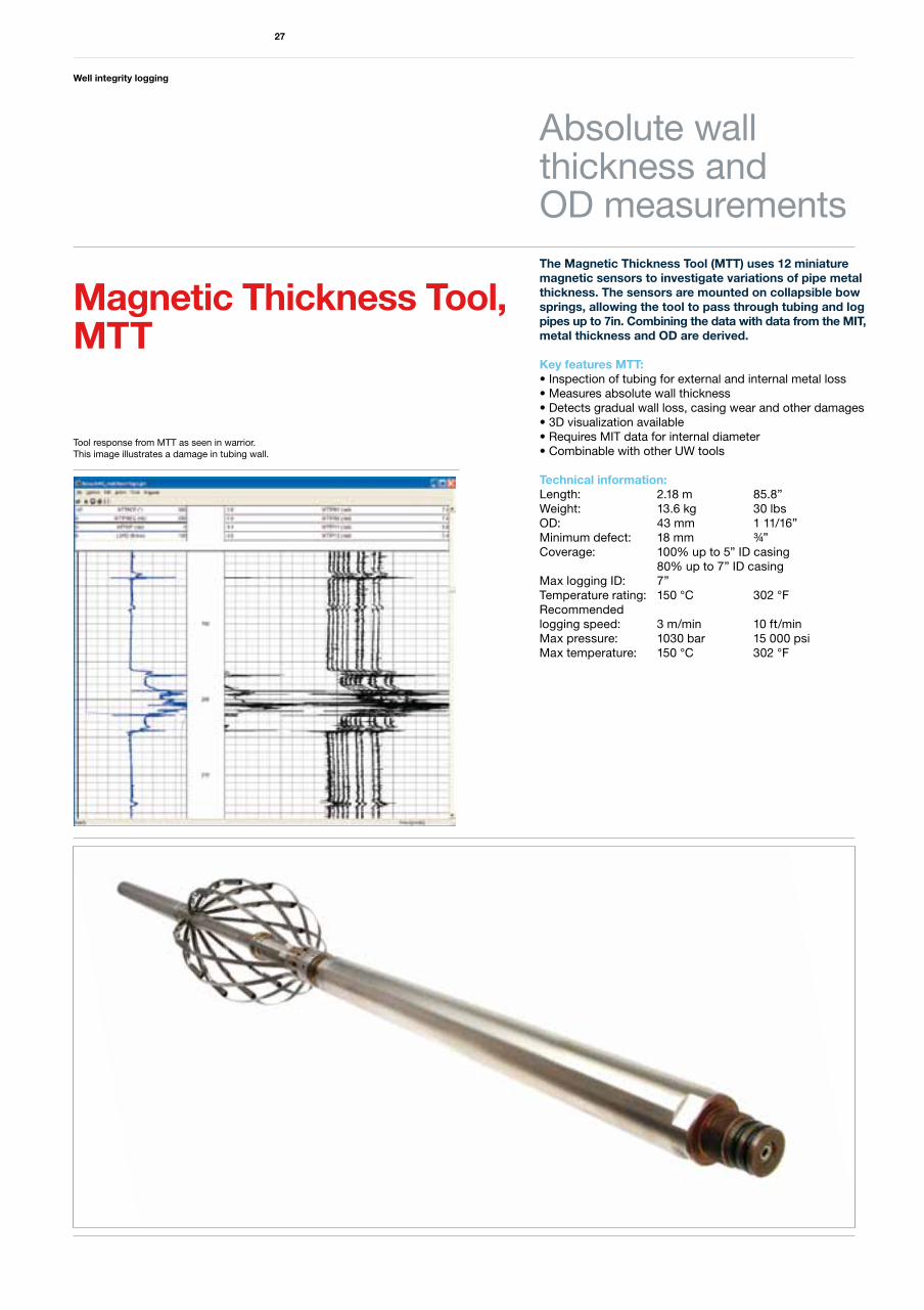
The Magnetic Thickness Tool (MTT) uses 12 miniature magnetic sensors to investigate variations of pipe metal thickness. The sensors are mounted on collapsible bow springs, allowing the tool to pass through tubing and log pipes up to 7in. Combining the data with data from the MIT, metal thickness and OD are derived.
Key features MTT:• Inspection of tubing for external and internal metal loss• Measures absolute wall thickness• Detects gradual wall loss, casing wear and other damages• 3D visualization available• Requires MIT data for internal diameter• Combinable with other UW tools
Technical information:Length: 2.18 m 85.8”Weight: 13.6 kg 30 lbsOD: 43 mm 1 11/16”Minimum defect: 18 mm ¾”Coverage: 100% up to 5” ID casing 80% up to 7” ID casingMax logging ID: 7”Temperature rating: 150 °C 302 °FRecommended logging speed: 3 m/min 10 ft/minMax pressure: 1030 bar 15 000 psiMax temperature: 150 °C 302 °F
Absolute wall thickness and OD measurements
Magnetic Thickness Tool, MTT
Tool response from MTT as seen in warrior. This image illustrates a damage in tubing wall.
Well integrity logging
28
In the increasingly harsh environments and extended well life that we often encounter in the industry the issue of well integrity is becoming more and more important.
Many operators now find it crucially important to try to understand the levels of corrosive damage and/or physical deformations that are present in their wells. In addition many operators have to deal with scale deposits that have serious repercussions on the flow efficiency of the completions.
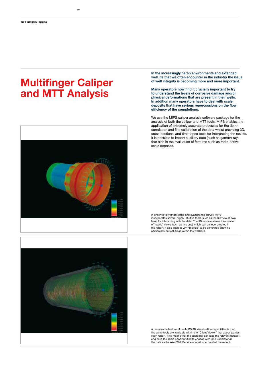
We use the MIPS caliper analysis software package for the analysis of both the caliper and MTT tools. MIPS enables the application of extremely accurate processes for the depth correlation and fine calibration of the data whilst providing 3D, cross-sectional and time-lapse tools for interpreting the results. It is possible to import auxiliary data (such as gamma-ray) that aids in the evaluation of features such as radio-active scale deposits.
Multifinger Caliper and MTT Analysis
In order to fully understand and evaluate the survey MIPS incorporates several highly intuitive tools (such as the 3D view shown here) for interacting with the data. The 3D module allows the creation of “static” views (such as this one) which can be incorporated in the report; it also enables .avi “movies” to be generated showing particularly critical areas within the wellbore.
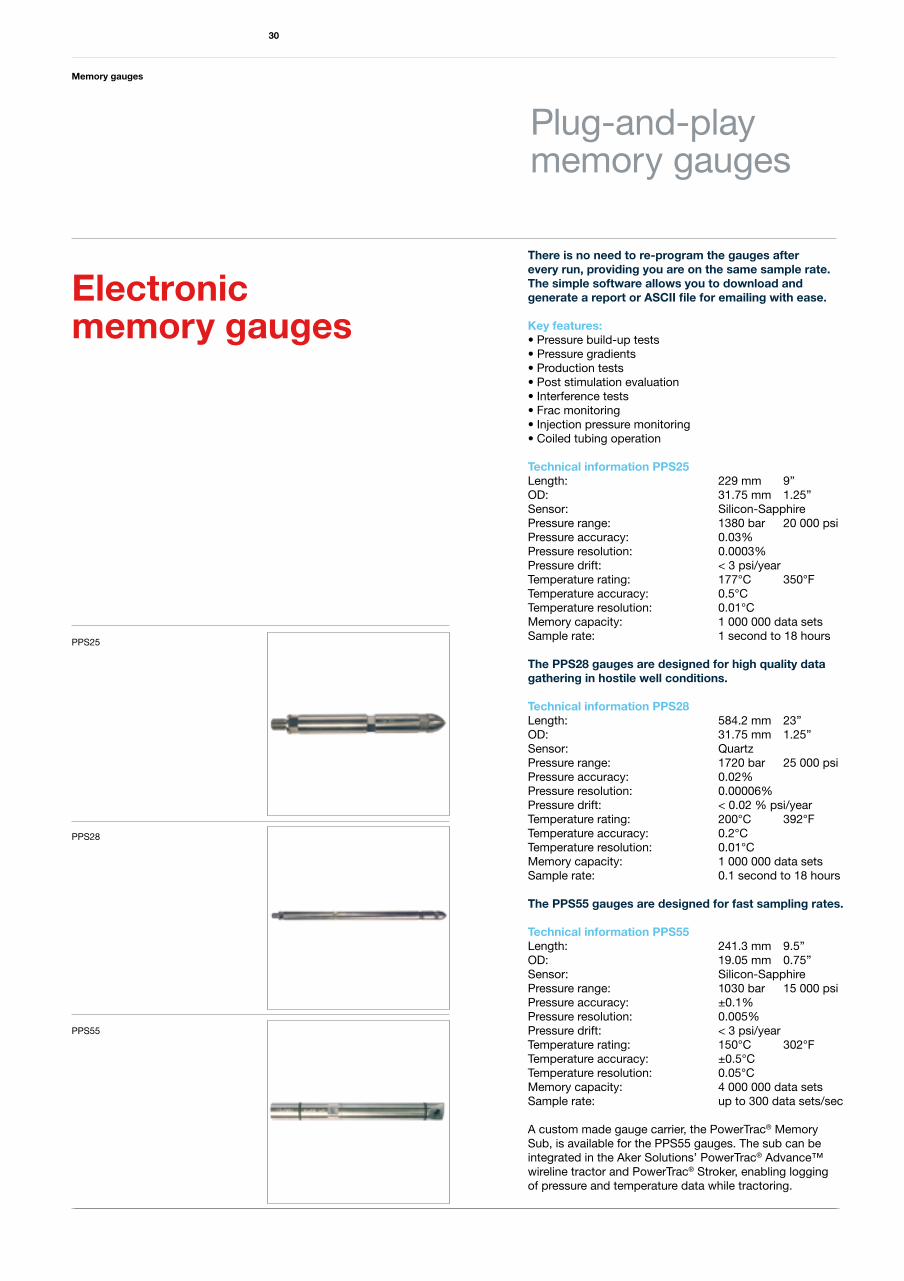
A remarkable feature of the MIPS 3D visualisation capabilities is thatthe same tools are available within the “Client Viewer” that accompanieseach report. This means that the customer can load the relevant datasetand have the same opportunities to engage with (and understand)the data as the Aker Well Service analyst who created the report.

Memory gauges
29
Electronic memory gauges
Memory gauges in use are either high resolution Quartz or lower resolution Sapphire sensors measuring downhole pressure and temperature versus time. The gauges are designed to be run by wireline/service personnel with limited knowledge or experience in running memory gauges.
Memory gauges
30
There is no need to re-program the gauges afterevery run, providing you are on the same sample rate. The simple software allows you to download and generate a report or ASCII file for emailing with ease.
Key features:• Pressure build-up tests• Pressure gradients• Production tests• Post stimulation evaluation• Interference tests• Frac monitoring• Injection pressure monitoring• Coiled tubing operation
Technical information PPS25Length: 229 mm 9”OD: 31.75 mm 1.25”Sensor: Silicon-SapphirePressure range: 1380 bar 20 000 psiPressure accuracy: 0.03%Pressure resolution: 0.0003%Pressure drift: < 3 psi/yearTemperature rating: 177°C 350°FTemperature accuracy: 0.5°C Temperature resolution: 0.01°CMemory capacity: 1 000 000 data setsSample rate: 1 second to 18 hours
The PPS28 gauges are designed for high quality data gathering in hostile well conditions.
Technical information PPS28Length: 584.2 mm 23”OD: 31.75 mm 1.25”Sensor: QuartzPressure range: 1720 bar 25 000 psiPressure accuracy: 0.02%Pressure resolution: 0.00006%Pressure drift: < 0.02 % psi/year Temperature rating: 200°C 392°FTemperature accuracy: 0.2°CTemperature resolution: 0.01°CMemory capacity: 1 000 000 data setsSample rate: 0.1 second to 18 hours
The PPS55 gauges are designed for fast sampling rates.
Technical information PPS55Length: 241.3 mm 9.5”OD: 19.05 mm 0.75”Sensor: Silicon-SapphirePressure range: 1030 bar 15 000 psiPressure accuracy: ±0.1% Pressure resolution: 0.005%Pressure drift: < 3 psi/yearTemperature rating: 150°C 302°FTemperature accuracy: ±0.5°CTemperature resolution: 0.05°CMemory capacity: 4 000 000 data setsSample rate: up to 300 data sets/sec
A custom made gauge carrier, the PowerTrac® Memory Sub, is available for the PPS55 gauges. The sub can be integrated in the Aker Solutions’ PowerTrac® Advance™ wireline tractor and PowerTrac® Stroker, enabling logging of pressure and temperature data while tractoring.
Plug-and-playmemory gauges
Electronic memory gauges
PPS28
PPS25
PPS55
Explosive services
31
Correlation, plug setting,explosive services
Aker Well Service is a total supplier of explosive services. We can correlate and set close to every plug and fire any gun system available on the market.
Explosive services
32
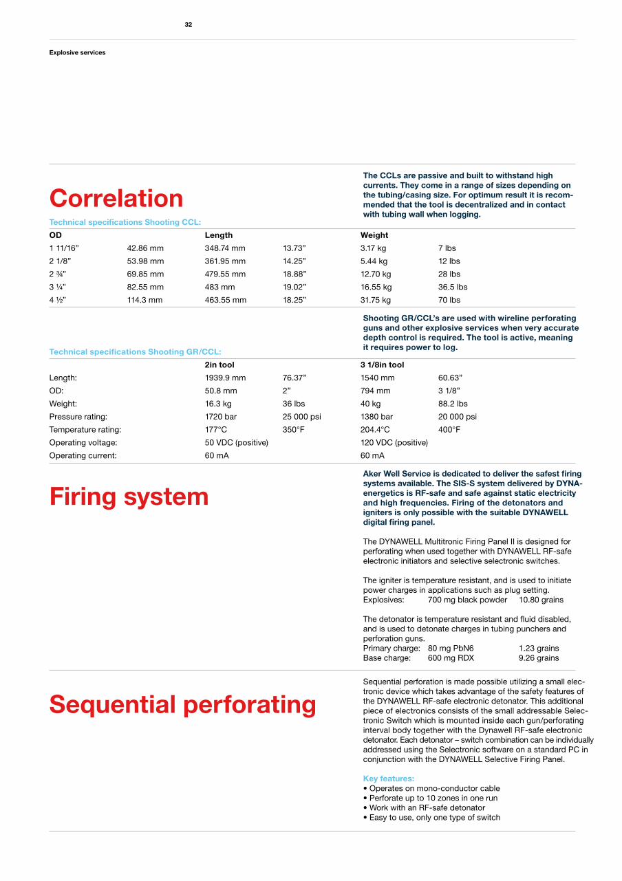
The CCLs are passive and built to withstand high currents. They come in a range of sizes depending on the tubing/casing size. For optimum result it is recom-mended that the tool is decentralized and in contact with tubing wall when logging.
Shooting GR/CCL’s are used with wireline perforating guns and other explosive services when very accurate depth control is required. The tool is active, meaning it requires power to log.
Technical specifications Shooting CCL:
OD Length Weight
1 11/16” 42.86 mm 348.74 mm 13.73” 3.17 kg 7 lbs
2 1/8” 53.98 mm 361.95 mm 14.25” 5.44 kg 12 lbs
2 ¾” 69.85 mm 479.55 mm 18.88” 12.70 kg 28 lbs
3 ¼” 82.55 mm 483 mm 19.02” 16.55 kg 36.5 lbs
4 ½” 114.3 mm 463.55 mm 18.25” 31.75 kg 70 lbs
Technical specifications Shooting GR/CCL:
2in tool 3 1/8in tool
Length: 1939.9 mm 76.37” 1540 mm 60.63”
OD: 50.8 mm 2” 794 mm 3 1/8”
Weight: 16.3 kg 36 lbs 40 kg 88.2 lbs
Pressure rating: 1720 bar 25 000 psi 1380 bar 20 000 psi
Temperature rating: 177°C 350°F 204.4°C 400°F
Operating voltage: 50 VDC (positive) 120 VDC (positive)
Operating current: 60 mA 60 mA
Correlation
Aker Well Service is dedicated to deliver the safest firing systems available. The SIS-S system delivered by DYNA-energetics is RF-safe and safe against static electricity and high frequencies. Firing of the detonators andigniters is only possible with the suitable DYNAWELL digital firing panel.
The DYNAWELL Multitronic Firing Panel II is designed for perforating when used together with DYNAWELL RF-safe electronic initiators and selective selectronic switches.
The igniter is temperature resistant, and is used to initiate power charges in applications such as plug setting.Explosives: 700 mg black powder 10.80 grains
The detonator is temperature resistant and fluid disabled,and is used to detonate charges in tubing punchers and perforation guns.Primary charge: 80 mg PbN6 1.23 grainsBase charge: 600 mg RDX 9.26 grains
Sequential perforation is made possible utilizing a small elec-tronic device which takes advantage of the safety features of the DYNAWELL RF-safe electronic detonator. This additional piece of electronics consists of the small addressable Selec-tronic Switch which is mounted inside each gun/perforating interval body together with the Dynawell RF-safe electronic detonator. Each detonator – switch combination can be individually addressed using the Selectronic software on a standard PC in conjunction with the DYNAWELL Selective Firing Panel.
Key features:• Operates on mono-conductor cable• Perforate up to 10 zones in one run• Work with an RF-safe detonator• Easy to use, only one type of switch
Firing system
Sequential perforating
Explosive services
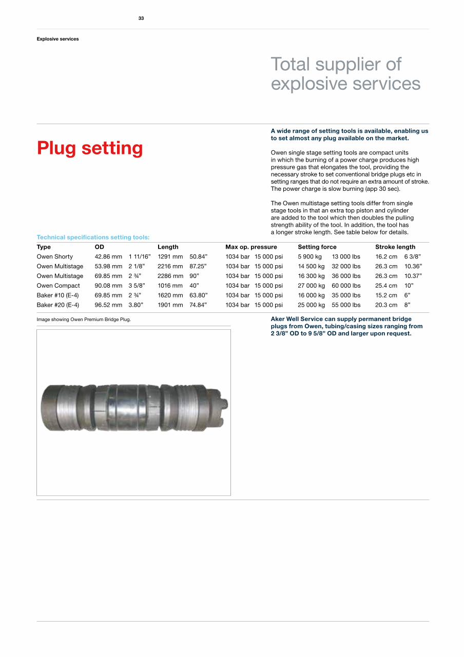
A wide range of setting tools is available, enabling us to set almost any plug available on the market.
Owen single stage setting tools are compact units in which the burning of a power charge produces high pressure gas that elongates the tool, providing the necessary stroke to set conventional bridge plugs etc in setting ranges that do not require an extra amount of stroke. The power charge is slow burning (app 30 sec).
The Owen multistage setting tools differ from single stage tools in that an extra top piston and cylinder are added to the tool which then doubles the pulling strength ability of the tool. In addition, the tool has a longer stroke length. See table below for details.
Aker Well Service can supply permanent bridge plugs from Owen, tubing/casing sizes ranging from 2 3/8” OD to 9 5/8” OD and larger upon request.
Technical specifications setting tools:
Type OD Length Max op. pressure Setting force Stroke length
Owen Shorty 42.86 mm 1 11/16” 1291 mm 50.84” 1034 bar 15 000 psi 5 900 kg 13 000 lbs 16.2 cm 6 3/8”
Owen Multistage 53.98 mm 2 1/8” 2216 mm 87.25” 1034 bar 15 000 psi 14 500 kg 32 000 lbs 26.3 cm 10.36”
Owen Multistage 69.85 mm 2 ¾” 2286 mm 90” 1034 bar 15 000 psi 16 300 kg 36 000 lbs 26.3 cm 10.37”
Owen Compact 90.08 mm 3 5/8” 1016 mm 40” 1034 bar 15 000 psi 27 000 kg 60 000 lbs 25.4 cm 10”
Baker #10 (E-4) 69.85 mm 2 ¾” 1620 mm 63.80” 1034 bar 15 000 psi 16 000 kg 35 000 lbs 15.2 cm 6”
Baker #20 (E-4) 96.52 mm 3.80” 1901 mm 74.84” 1034 bar 15 000 psi 25 000 kg 55 000 lbs 20.3 cm 8”
33
Plug setting
Total supplier ofexplosive services
Image showing Owen Premium Bridge Plug.
Charges 1 9/16” tubing puncher:
Grams Colour code Entry hole Wall thickness
2 Red 0.39” ¼” – 3/8”
3 Green 0.41” 3/8” – ½”
4 White 0.40” ½” – 5/8”
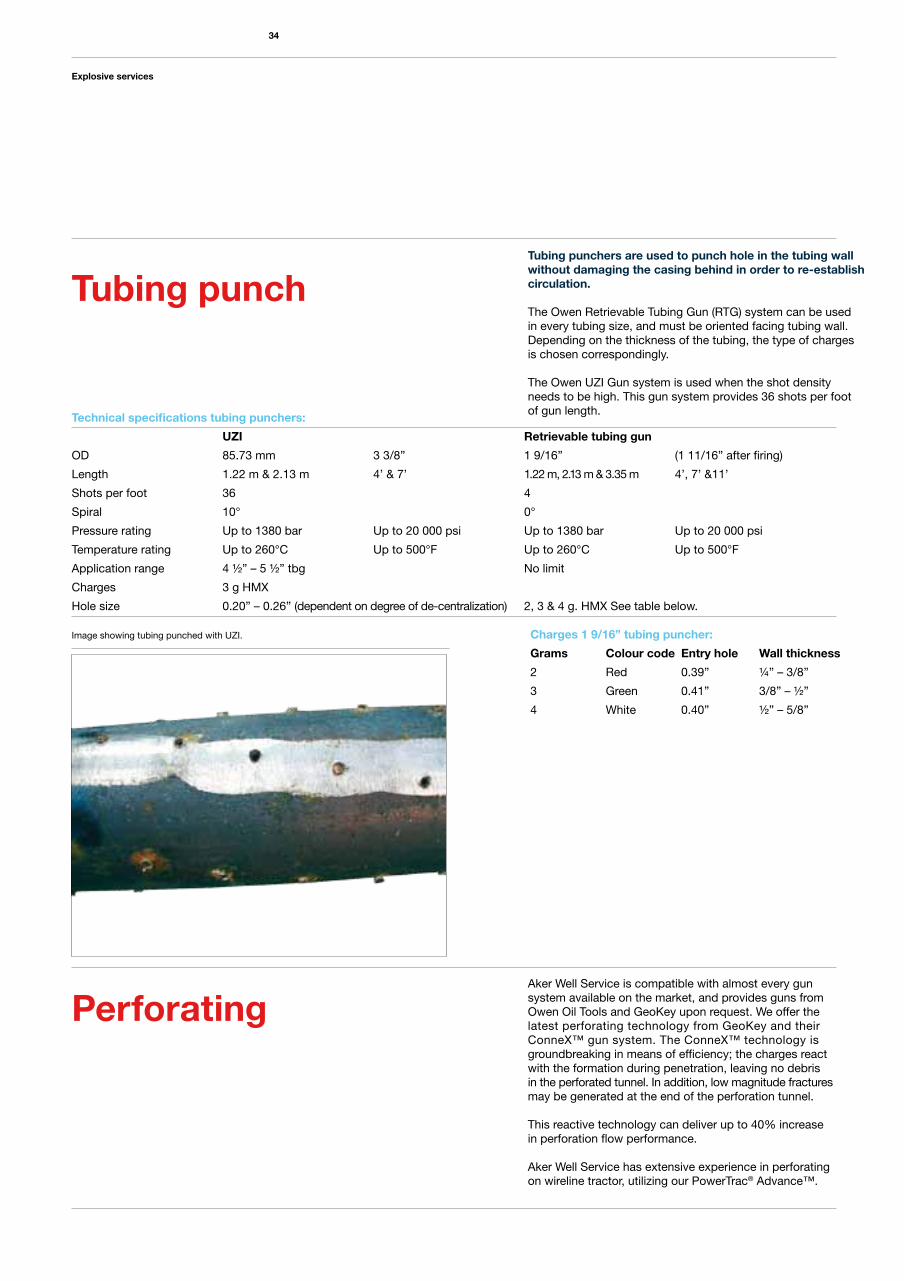
Tubing punchers are used to punch hole in the tubing wall without damaging the casing behind in order to re-establish circulation.
The Owen Retrievable Tubing Gun (RTG) system can be used in every tubing size, and must be oriented facing tubing wall. Depending on the thickness of the tubing, the type of charges is chosen correspondingly.
The Owen UZI Gun system is used when the shot density needs to be high. This gun system provides 36 shots per foot of gun length. Technical specifications tubing punchers:
UZI Retrievable tubing gun
OD 85.73 mm 3 3/8” 1 9/16” (1 11/16” after firing)
Length 1.22 m & 2.13 m 4’ & 7’ 1.22 m, 2.13 m & 3.35 m 4’, 7’ &11’
Shots per foot 36 4
Spiral 10° 0°
Pressure rating Up to 1380 bar Up to 20 000 psi Up to 1380 bar Up to 20 000 psi
Temperature rating Up to 260°C Up to 500°F Up to 260°C Up to 500°F
Application range 4 ½” – 5 ½” tbg No limit
Charges 3 g HMX
Hole size 0.20” – 0.26” (dependent on degree of de-centralization) 2, 3 & 4 g. HMX See table below.
Tubing punch
Image showing tubing punched with UZI.
Explosive services
34
Aker Well Service is compatible with almost every gun system available on the market, and provides guns from Owen Oil Tools and GeoKey upon request. We offer the latest perforating technology from GeoKey and their ConneX™ gun system. The ConneX™ technology is groundbreaking in means of efficiency; the charges react with the formation during penetration, leaving no debris in the perforated tunnel. In addition, low magnitude fractures may be generated at the end of the perforation tunnel.
This reactive technology can deliver up to 40% increase in perforation flow performance.
Aker Well Service has extensive experience in perforating on wireline tractor, utilizing our PowerTrac® Advance™.
Perforating
Aker Well Service AS is a subsidiary of Aker Solutions ASA, which through its subsidiaries and affiliates (“Aker Solutions”), is a leading global provider of engineering and construction services, technology products and integrated solutions. The Aker Solutions group is organized in a number of separate legal entities. Aker Solutions is used as the common brand/trademark for most of these entities. Aker Solutions’ parent company is Aker Solutions ASA. Aker Solutions has aggregated annual revenues of approximately NOK 58 billion and employs approximately 26 000 people in about 30 countries. Aker Solutions is part of Aker (www.akerasa.com), a group of premier companies with a focus on energy, maritime and marine resource industries. The Aker companies share a common set of values and a long tradition of industrial innovation. As an industrial owner controlling 40.27 percent of the shares in Aker Solutions through Aker Holding AS, Aker ASA takes an active role in the development of Aker Solutions.
About Aker Solutions
Logging services
Head office, North Sea area: Aker Well Service AS Lagerveien 30 P.O.Box 281 N-4066 Stavanger NorwayTel: +47 51 95 16 00 Fax: +47 51 95 16 01
Canada office: Aker Well Service a Division of Aker Solutions Oilfield Services Canada Inc.#300,6835 Railway Street S.E. Calgary, Alberta T2H 2V6 CanadaMb: +1 403 606 6322Tel: +1 403 212 3611Fax: +1 403 252 1186
© 2009 Aker Solutions Well ServiceAll rights reserved.www.akersolutions.com/wellservice
Caspian Sea area: Aker Well Service AS Black CityBaku AZ1025 AZERBAIJANMb: +994 50 7467006Tel: +994 12 4908288Fax: +994 12 4908289
Middle East area: Aker Well Service LLC Al Khuwair Street Al Khuwair House 2nd Floor, Office No. 21 Al Khuwair, Sultanate of OmanMuscatTel: +968 2448 0702 Fax: +968 2448 0360
www.akersolutions.com/wellservice
Aker Solutions’ centres for well services:
Aker Well Service L.L.C - (Saudi)P.O Box 402, Al-Khobar 31952Kingdom of Saudi ArabiaTel: +966 3 8575353Fax: +966 3 8470575
UK office: Aker Qserv LtdBadentoy CrescentPortlethen Aberdeen AB12 4YD UKTel: +44 (0) 1224 78 3707Fax: +44 (0) 1224 78 3702
USA office: Aker Well Service Inc.2201 North Sam Houston Pkwy Houston, Texas 77038 USAMb: +1 281 799 0392Tel: +1 713 683 2805 Fax: +1 713 683 2866
adsign
.no