Embed Size (px)
Citation preview
User’sManual
IM 04L51B01-06EN4th Edition
Model GX10/GX20/GP10/GP20/GM10
Log Scale (/LG)User’s Manual


iIM 04L51B01-06EN
IntroductionThank you for purchasing the SMARTDAC+ Series GX10/GX20/GP10/GP20/GM10 (hereafter referred to as the recorder, GX, GP, or GM).This manual explains the Log scale (/LG option) function of the GX, GP, and GM.Although the display of GX20 is used in this manual, GX10/GP10/GP20 can be operated similarly. Moreover, for the GM10, the same content can be displayed on a Web browser.To ensure correct use, please read this manual thoroughly before beginning operation.For details on other settings, procedures, and communication features, read also the following user’s manuals.• Model GX10/GX20/GP10/GP20 Paperless Recorder User’s Manual (IM 04L51B01-01EN)• Data Acquisition System GM User’s Manual (IM 04L55B01-01EN)• Model GX10/GX20/GP10/GP20/GM10 Communication Command User’s Manual (IM
04L51B01-17EN)
The following manuals are provided for the GX/GP.
• Paper Manuals Manual Title Manual No. DescriptionModel GX10/GX20/GP10/GP20Paperless RecorderFirst Step Guide
IM 04L51B01-02EN Explains the basic operations of the GX/GP.
• Downloadable Electronic ManualsYou can download the latest manuals from the following website.www.smartdacplus.com/manual/en/
Model Manual Title Manual No. DescriptionGX/GP Model GX10/GX20/GP10/GP20
Paperless Recorder First Step Guide
IM 04L51B01-02EN This is the electronic version of the paper manual.
Model GX10/GX20/GP10/GP20Paperless RecorderUser’s Manual
IM 04L51B01-01EN Describes how to use the GX/GP. The communication control commands and some of the options are excluded.
Model GX10/GX20/GP10/GP20Advanced Security Function (/AS)User’s Manual
IM 04L51B01-05EN Describes how to use the advanced security function (/AS option).
GM GM Data Acquisition SystemFirst Step Guide
IM 04L55B01-02EN This is the electronic version of the paper manual.
GM Data Acquisition SystemUser’s Manual
IM 04L55B01-01EN Describes how to use the GM. The communication control commands and some of the options are excluded.
GM Data Acquisition SystemAdvanced Security Function (/AS)User’s Manual
IM 04L55B01-05EN Describes how to use the advanced security function (/AS option).
GX/GPGM
Model GX10/GX20/GP10/GP20/GM10Communication CommandsUser’s Manual
IM 04L51B01-17EN Describes how to use command control communication functions.
SMARTDAC+ STANDARDUniversal ViewerUser’s Manual
IM 04L61B01-01EN Describes how to use Universal Viewer, which is a software that displays GX/GP/GM measurement data files.
SMARTDAC+ STANDARDHardware ConfiguratorUser’s Manual
IM 04L61B01-02EN Describes how to use the PC software for creating setting parameters for various GX/GP/GM functions.
Model GX10/GX20/GP10/GP20/GM10Multi-batch Function (/BT)User’s Manual
IM 04L51B01-03EN Describes how to use the multi-batch function (/BT option).
Model GX10/GX20/GP10/GP20/GM10Log Scale (/LG)User’s Manual
IM 04L51B01-06EN Describes how to use the log scale (/LG option).
Model GX10/GX20/GP10/GP20/GM10EtherNet/IP Communication (/E1)User’s Manual
IM 04L51B01-18EN Describes how to use the communication functions through the EtherNet/IP (/E1 option).
Model GX10/GX20/GP10/GP20/GM10WT Communication (/E2)User’s Manual
IM 04L51B01-19EN Describes how to use WT communication (/E2 option).
Model GX10/GX20/GP10/GP20/GM10OPC-UA Server (/E3)User’s Manual
IM 04L51B01-20EN Describes how to use the OPC-UA server function (/E3 option).
Model GX10/GX20/GP10/GP20/GM10SLMP Communication (/E4)User’s Manual
IM 04L51B01-21EN Describes how to use SLMP communication function (/E4 option).
Model GX10/GX20/GP10/GP20/GM10Loop Control Function, Program Control Function (/PG Option)User’s Manual
IM 04L51B01-31EN Describes how to use the Loop Control Function, Program Control Function (/PG Option).
Continued on the next page
4th Edition: May 2020 (YK)All Rights Reserved, Copyright © 2014, Yokogawa Electric Corporation
ii IM 04L51B01-06EN
Model Manual Title Manual No. DescriptionGX/GP DXA170
DAQStudioUser’s Manual
IM 04L41B01-62EN Describes how to create custom displays (/CG option).
Notes• The contents of this manual are subject to change without prior notice as a result of
continuing improvements to the instrument’s performance and functions.• Every effort has been made in the preparation of this manual to ensure the accuracy of its
contents. However, should you have any questions or find any errors, please contact your nearest YOKOGAWA dealer.
• Copying or reproducing all or any part of the contents of this manual without the permission of YOKOGAWA is strictly prohibited.
QR CodeThe product has a QR Code pasted for efficient plant maintenance work and asset information management.It enables confirming the specifications of purchased products and user’s manuals.For more details, please refer to the following URL.
https://www.yokogawa.com/qr-code
QR Code is a registered trademark of DENSO WAVE INCORPORATED.
Trademarks• SMARTDAC+ is registered trademarks of Yokogawa Electric Corporation.• Microsoft and Windows are registered trademarks or trademarks of Microsoft Corporation
in the United States and/or other countries.• Adobe and Acrobat are registered trademarks or trademarks of Adobe Systems
Incorporated.• Company and product names that appear in this manual are registered trademarks or
trademarks of their respective holders.• The company and product names used in this manual are not accompanied by the
registered trademark or trademark symbols (® and ™).
Using Open Source SoftwareThis product uses open source software.For details on using open source software, see Regarding the Downloading and Installing for the Software, Manuals and Labels (IM 04L61B01-11EN).
RevisionsMay 2014 1st EditionDecember 2014 2nd EditionJune 2017 3rd EditionMay 2020 4th Edition
iiiIM 04L51B01-06EN
Recorder Versions Described in This ManualThe contents of this manual correspond to the GX/GP with release number 4 (see the STYLE S number) and style number 3 (GX10/GX20/GP10), style number 4 (GP20) (see the STYLE H number) and the GM10 with release number 4 (see the STYLE S number) and style number 1 (see the STYLE H number).Edition Product Explanation1 GX/GP: Version 2.01 and later —2 GX/GP: Version 2.01 and later Describes the GM.
GM: Version 2.02 and later3 GX/GP: Version 4.01 and later Support for Release number 4.
GM: Version 4.01 and later4 GX/GP: Version 4.08 and later Support for style up (H: 3 (GX10/GX20/GP10), H: 4
(GP20)).GM: Version 4.07 and later —
iv IM 04L51B01-06EN
Conventions Used in This ManualUnit
K Denotes 1024. Example: 768K (file size)k Denotes 1000.
MarkingsImproper handling or use can lead to injury to the user or damage to the instrument. This symbol appears on the instrument to indicate that the user must refer to the user’s manual for special instructions. The same symbol appears in the corresponding place in the user’s manual to identify those instructions. In the manual, the symbol is used in conjunction with the word “WARNING” or “CAUTION.”
WARNING Calls attention to actions or conditions that could cause serious or fatal injury to the user, and precautions that can be taken to prevent such occurrences.
CAUTION Calls attention to actions or conditions that could cause light injury to the user or cause damage to the instrument or user’s data, and precautions that can be taken to prevent such occurrences.
Note Calls attention to information that is important for the proper operation of the instrument.
Reference ItemReference to related operation or explanation is indicated after this mark.Example: section 4.1
Conventions Used in the Procedural ExplanationsBold characters Denotes key or character strings that appear on the screen.
Example: VoltA a # 1 Indicates the character types that can be used.
a symbol, uppercase alphabet,numbers
A
1
lowercase alphabet, #
Procedure Carry out the procedure according to the step numbers. All procedures are written with inexperienced users in mind; depending on the operation, not all steps need to be taken.Explanation gives information such as limitations related the procedure.
Explanation
Path Indicates the setup screen and explains the settings.
Description
Module NotationWhen necessary, the following notations are used to distinguish the GX90XA analog input modules by type.Type Suffix Code Notation-U2 Universal-C1 Current (mA)-L1 Low withstand voltage relay-T1 Electromagnetic relay-H0 High-speed universal or High speed AI-R1 4-wire RTD/resistance
vIM 04L51B01-06EN
Contents
Introduction ................................................................................................................................................ iRecorder Versions Described in This Manual ..........................................................................................iiiConventions Used in This Manual ........................................................................................................... iv
Using the Log scale Function ............................................................................................................. 1Log Scale Display Function ...................................................................................................................... 1Restrictions ............................................................................................................................................... 2
Setting the Log scale ........................................................................................................................... 3AI channel settings ................................................................................................................................... 3Setup Examples ..................................................................................................................................... 13

Blank
1IM 04L51B01-06EN
Using the Log scale Function
Log Scale Display FunctionYou can apply a logarithmic voltage that has been converted from a physical value to the recorder, and then use the log scale (logarithmic scale) to display and record the physical value. The recorder supports three types of input signals.• Logarithmic Input This is referred to as “Log input”. Log input is input in which the voltage corresponds to
logarithmic values of physical values.• Pseudo Log Input This is referred to as “Pseud-log input.” This input supports pseudo logs. A pseudo log signal is a voltage obtained by summing the one’s digit of the voltage
representing the exponent of the logarithmic data and the decimal digits of the voltage representing the mantissa.
• Input That Is Linear on a Logarithmic Scale This is referred to as “Linear-Log input.” Linear log input is input in which the voltage
values correspond to the logarithmic values of physical values at each decade division (for example, 1 × 10²) and in which, within each decade, the voltage values correspond linearly to physical values.
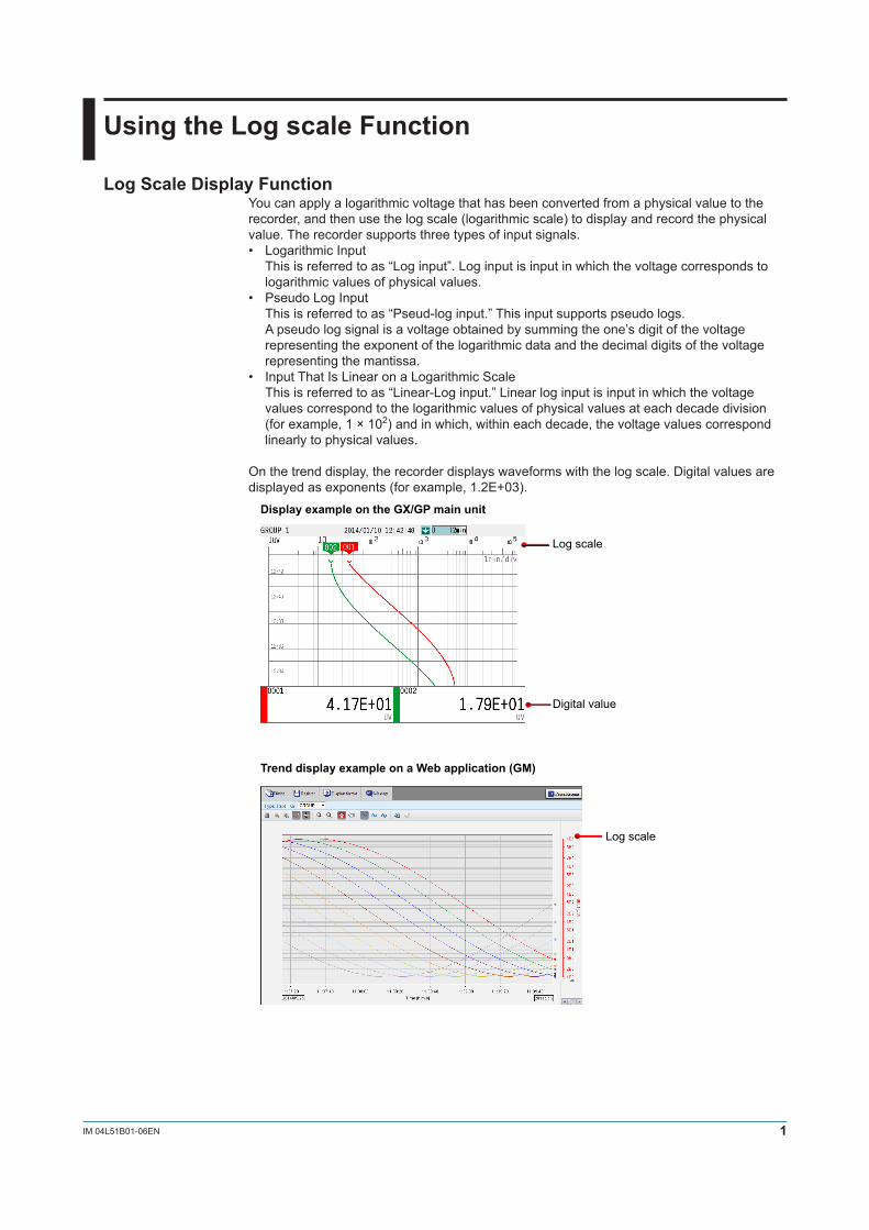
On the trend display, the recorder displays waveforms with the log scale. Digital values are displayed as exponents (for example, 1.2E+03).
Display example on the GX/GP main unit
Trend display example on a Web application (GM)
Log scale
Digital value
Log scale
2 IM 04L51B01-06EN
RestrictionsPartialYou cannot set the partial display on a channel that is set to log scale.
Differential Computation between ChannelsIf you set the reference channel of a differential computation between channels to a channel that is set to log scale, an error will be returned as the measured result of the differential computation between channels.
Computation Channels (/MT option)Do not include channels that are set to log scale in a computation channel expression. If you include these channels, an error will be returned as the measured result.
Report Function (/MT option)You cannot create reports for channels that are set to log scale. An error will be returned as the result of report computations on channels that are set to log scale.
Manual Sampled DataFor channels that are set to log scale, the data is stored using the “mantissa + exponent” format, the same format as that of digital values on the recorder.
Number of Channels Set to Log ScaleKeep the number of channels set to log scale no greater than 300.When there are many channels set to log scale, log scale processing may not finish within the scan interval and may cause computation data dropouts.
Using the Log scale Function
3IM 04L51B01-06EN
Setting the Log scale
AI channel settingsLog input computation cannot be specified on current (mA), 4-wire RTD/resistance modules.
Range settings
PathGX/GP: MENU key > Browse tab > Setting > Setting menu AI channel settings > RangeWeb application: Config. tab > AI channel settings > Channel range (display example:
0001-0010) > RangeHardware configurator: AI channel settings > Channel range (display example: 0001-
0010) > Range
DescriptionSetup Item Selectable Range or Options Default ValueFirst-CH AI channel —Last-CH AI channel —
First-CH, Last-CHSet the target channels. The channels that you can specify appear depending on the module configuration.
RangeSetup Item Selectable Range or Options Default ValueType Skip, Volt, GS (general signal), TC
(thermocouple), RTD (resistance temperature detector)1, DI (contact, voltage level)
Volt
Range See “Range Details.” See “Range Details.”Span Lower Numeric value (depends on the range) –2.0000Span Upper Numeric value (depends on the range) 2.0000Calculation Off, Delta, Linear scaling, Square root,
Log input, Pseudo-Log input, Linear-Log input
Off
1 Cannot be specified for the electromagnetic relay type analog input module and low withstand voltage relay type.
TypeSet the type to Volt. You cannot use the log scale display for any other type.
NoteFor the channels in which you are not using an electromagnetic relay type module, set the rangetype to Skip.
4 IM 04L51B01-06EN
RangeSet the input type range.
Range DetailsType Range Selectable Range Default ValueVolt 20mV –20.000 mV to 20.000 mV 2V
60mV –60.00 mV to 60.00 mV200mV –200.00 mV to 200.00 mV1V –1.0000 V to 1.0000 V2V –2.0000 V to 2.0000 V6V –6.000 V to 6.000 V20V –20.000 V to 20.000 V50V –50.00 V to 50.00 V100V1 –100.00 V to 100.00 V
1 For high-speed universal type.
Span Lower, Span UpperSet the input range. The selectable range varies depending on the range setting.For the selectable ranges, see “Range Details.”
NoteYou cannot set the same value to Span Lower and Span Upper.
CalculationSet the log scale type to Log input, Pseudo-log input, or Linear-log input.
Scale1
Setup Item Selectable Range or Options Default ValueDecimal place 1, 2 2Scale Lower Log input: 1.00E‒15 to 1.00E+14
Linear-Log, Pseudo-Log: 1.00E–15 to 1.00E+15
1.00E+00
Scale Upper Log input: 1.00E‒14 to 1.00E+15Linear-Log, Pseudo-Log; 1.00E–15 to 1.00E+15
1.00E+15
Unit Character string (up to 6 characters, A a # 1 ) —
1 Appears when the range calculation is set to Log input, Pseudo-log input, or Linear-log input.
Decimal PlaceSet the decimal place for scale lower and scale upper.This value is also applied to the lower and upper limits of the displayed point of color scale band as well as alarm values.
Scale Lower, Scale UpperSet the Scale Lower and Scale Upper.
Setting the Log scale
5IM 04L51B01-06EN
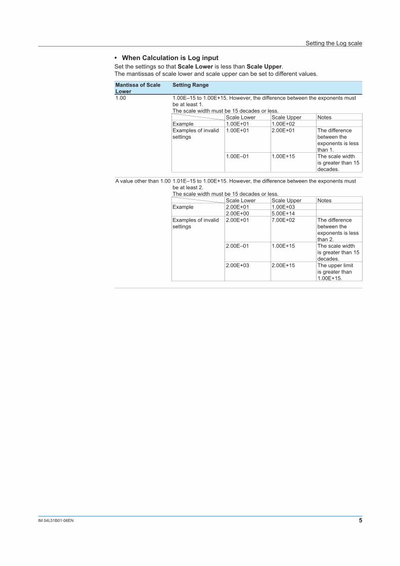
• When Calculation is Log inputSet the settings so that Scale Lower is less than Scale Upper.The mantissas of scale lower and scale upper can be set to different values.
Mantissa of Scale Lower
Setting Range
1.00 1.00E‒15 to 1.00E+15. However, the difference between the exponents must be at least 1.The scale width must be 15 decades or less.
Scale Lower Scale Upper NotesExample 1.00E+01 1.00E+02Examples of invalid settings
1.00E+01 2.00E+01 The difference between the exponents is less than 1.
1.00E‒01 1.00E+15 The scale width is greater than 15 decades.
A value other than 1.00 1.01E‒15 to 1.00E+15. However, the difference between the exponents must be at least 2.The scale width must be 15 decades or less.
Scale Lower Scale Upper NotesExample 2.00E+01 1.00E+03
2.00E+00 5.00E+14Examples of invalid settings
2.00E+01 7.00E+02 The difference between the exponents is less than 2.
2.00E‒01 1.00E+15 The scale width is greater than 15 decades.
2.00E+03 2.00E+15 The upper limit is greater than 1.00E+15.
Setting the Log scale
6 IM 04L51B01-06EN
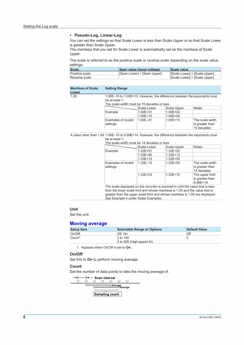
• Pseudo-Log, Linear-LogYou can set the settings so that Scale Lower is less than Scale Upper or so that Scale Lower is greater than Scale Upper.The mantissa that you set for Scale Lower is automatically set as the mantissa of Scale Upper.
The scale is referred to as the positive scale or reverse scale depending on the scale value settings.Scale Span value (Input voltage) Scale valuePositive scale [Span Lower] < [Span Upper] [Scale Lower] < [Scale Upper]Reverse scale [Scale Lower] > [Scale Upper]
Mantissa of Scale Lower
Setting Range
1.00 1.00E–15 to 1.00E+15. However, the difference between the exponents must be at least 1.The scale width must be 15 decades or less.
Scale Lower Scale Upper NotesExample 1.00E+01 1.00E+02
1.00E+15 1.00E+00Examples of invalid settings
1.00E‒01 1.00E+15 The scale widthis greater than15 decades.
A value other than 1.00 1.00E–15 to 9.99E+14. However, the difference between the exponents must be at least 1.The scale width must be 14 decades or less
Scale Lower Scale Upper NotesExample 1.33E+01 1.33E+02
1.33E+00 1.33E+131.33E+13 1.33E+00
Examples of invalid settings
1.33E–15 1.33E+00 The scale widthis greater than14 decades.
1.33E+03 1.33E+15 The upper limitis greater than9.99E+14.
The scale displayed on the recorder is zoomed in until the value that is less than the lower scale limit and whose mantissa is 1.00 and the value that is greater than the upper scale limit and whose mantissa is 1.00 are displayed. See Example 4 under Scale Examples.
UnitSet the unit.
Moving averageSetup Item Selectable Range or Options Default ValueOn/Off Off, On OffCount1 2 to 100
2 to 500 (High-speed AI)2
1 Appears when On/Off is set to On.
On/OffSet this to On to perform moving average.
CountSet the number of data points to take the moving average of.
Average
Scan interval
Sampling count
Average
Setting the Log scale
7IM 04L51B01-06EN
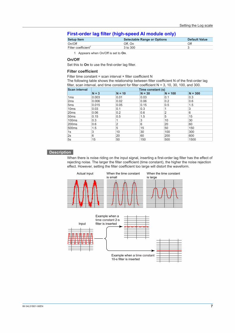
First-order lag filter (high-speed AI module only)Setup Item Selectable Range or Options Default ValueOn/Off Off, On OffFilter coefficient1 3 to 300 3
1 Appears when On/Off is set to On.
On/OffSet this to On to use the first-order lag filter.
Filter coefficientFilter time constant = scan interval × filter coefficient NThe following table shows the relationship between filter coefficient N of the first-order lag filter, scan interval, and time constant for filter coefficient N = 3, 10, 30, 100, and 300.Scan interval Time constant (s)
N = 3 N = 10 N = 30 N = 100 N = 3001ms 0.003 0.01 0.03 0.1 0.32ms 0.006 0.02 0.06 0.2 0.65ms 0.015 0.05 0.15 0.5 1.510ms 0.03 0.1 0.3 1 320ms 0.06 0.2 0.6 2 650ms 0.15 0.5 1.5 5 15100ms 0.3 1 3 10 30200ms 0.6 2 6 20 60500ms 1.5 5 15 50 1501s 3 10 30 100 3002s 6 20 60 200 6005s 15 50 150 500 1500
DescriptionWhen there is noise riding on the input signal, inserting a first-order lag filter has the effect of rejecting noise. The larger the filter coefficient (time constant), the higher the noise rejection effect. However, setting the filter coefficient too large will distort the waveform.
Actual input When the time constant is small
When the time constant is large
Input
Example when a time constant 2-s filter is inserted
Example when a time constant 10-s filter is inserted
Setting the Log scale
8 IM 04L51B01-06EN
BiasSetup Item Selectable Range or Options Default ValueValue Numeric value (–999999 to 999999) 0
ValueSet the bias to add to input values or linear scaling values (input calculation).
Input value Measured value
Bias (a constant value)
+
Channel on which bias is added
Scale ExamplesBelow are scale examples in which the trend direction is set to vertical on the GX/GP main unit. With the GM, the measurement data is displayed on a Web application, so the following items are different.• The trend is displayed with the time plotted on the horizontal axis. Therefore, the scale is
displayed vertically.• For example, a scale value of 1×10³ is displayed as “1E3.”• Scale marks other than decades (e.g., 1E3) are displayed only when there is space.
Log inputExample 1In this example, the mantissa of the scale lower limit and the mantissa of the scale upper limit are both 1.
Lower UpperSpan value (Input voltage) 1V 5VScale value 1.00E+01 1.00E+04
1E4
1E3
1E2
2E2
5E2
2E3
5E3
2E1
5E1
1E1
5V
1V
1V 5V
Display example on the GX/GP main unit Display example on a Web application (GM)
Displayed only when there is enough space.
Example 2In this example, the mantissa of the scale lower limit and the mantissa of the scale upper limit are both a value other than 1.
Lower UpperSpan value (Input voltage) 1V 5VScale value 5×1.00E+00 2×1.00E+04
1V 5V
25 10410310210
The end points of the scale are displayed using single digits if there is space to display them.
Setting the Log scale
9IM 04L51B01-06EN
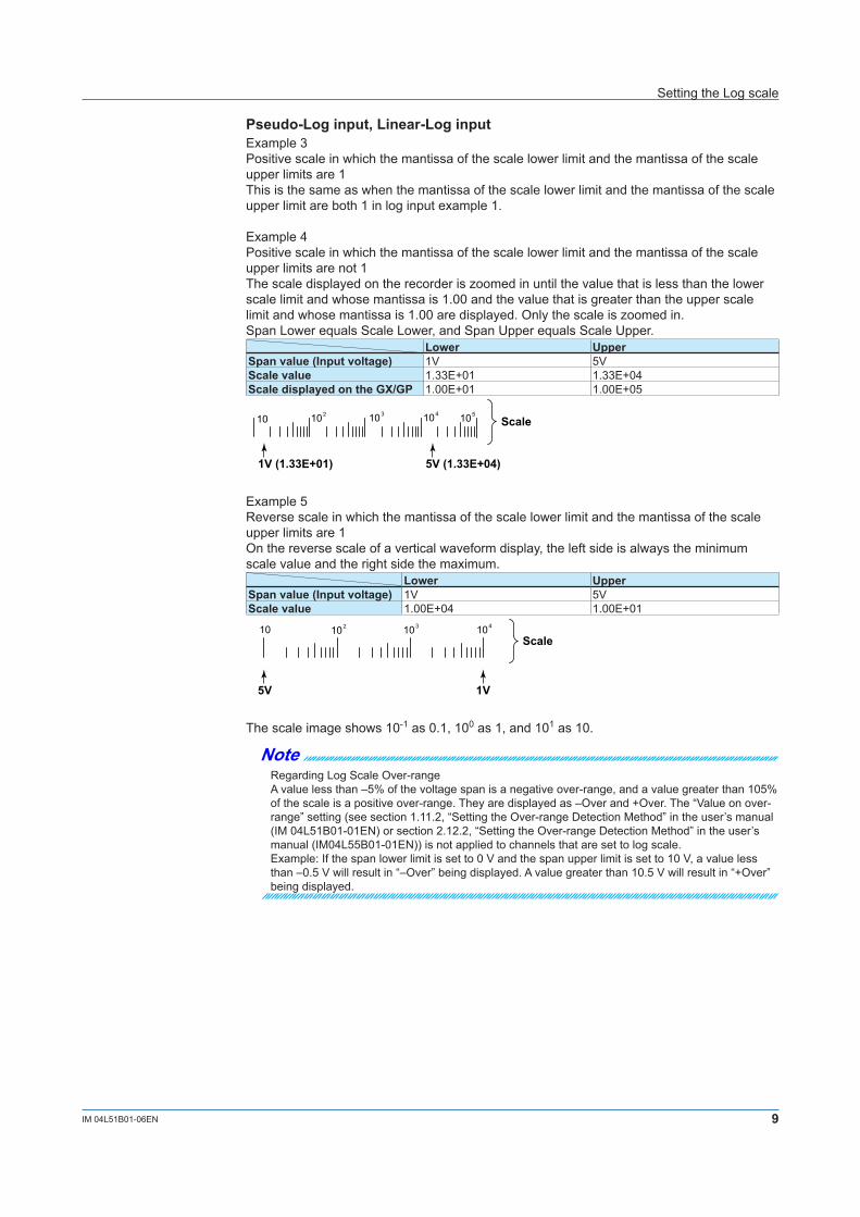
Pseudo-Log input, Linear-Log input Example 3Positive scale in which the mantissa of the scale lower limit and the mantissa of the scale upper limits are 1This is the same as when the mantissa of the scale lower limit and the mantissa of the scale upper limit are both 1 in log input example 1.
Example 4Positive scale in which the mantissa of the scale lower limit and the mantissa of the scale upper limits are not 1The scale displayed on the recorder is zoomed in until the value that is less than the lower scale limit and whose mantissa is 1.00 and the value that is greater than the upper scale limit and whose mantissa is 1.00 are displayed. Only the scale is zoomed in.Span Lower equals Scale Lower, and Span Upper equals Scale Upper.
Lower UpperSpan value (Input voltage) 1V 5VScale value 1.33E+01 1.33E+04Scale displayed on the GX/GP 1.00E+01 1.00E+05
5V (1.33E+04)
Scale
1V (1.33E+01)
104 10510310210
Example 5Reverse scale in which the mantissa of the scale lower limit and the mantissa of the scale upper limits are 1On the reverse scale of a vertical waveform display, the left side is always the minimum scale value and the right side the maximum.
Lower UpperSpan value (Input voltage) 1V 5VScale value 1.00E+04 1.00E+01
1V
Scale
5V
10410310210
The scale image shows 10-1 as 0.1, 100 as 1, and 101 as 10.
NoteRegarding Log Scale Over-rangeA value less than –5% of the voltage span is a negative over-range, and a value greater than 105% of the scale is a positive over-range. They are displayed as –Over and +Over. The “Value on over-range” setting (see section 1.11.2, “Setting the Over-range Detection Method” in the user’s manual (IM 04L51B01-01EN) or section 2.12.2, “Setting the Over-range Detection Method” in the user’s manual (IM04L55B01-01EN)) is not applied to channels that are set to log scale.Example: If the span lower limit is set to 0 V and the span upper limit is set to 10 V, a value less than –0.5 V will result in “–Over” being displayed. A value greater than 10.5 V will result in “+Over” being displayed.
Setting the Log scale
10 IM 04L51B01-06EN
Alarm settings
PathGX/GP: MENU key > Browse tab > Setting > Setting menu AI channel settings > AlarmWeb application: Config. tab > AI channel settings > Channel range (display example:
0001-0010) > AlarmHardware configurator: AI channel settings > Channel range (display example: 0001-0010)
> Alarm
DescriptionSetup Item Selectable Range or Options Default ValueFirst-CH AI channel —Last-CH AI channel —
First-CH, Last-CHSet the target channels. The channels that you can specify appear depending on the module configuration.
Level 1, Level 2, Level 3, Level 4Setup Item Selectable Range or Options Default ValueOn/Off Off, On OffType1 H: High limit, L: Low limit, T: Delay high limit, t: Delay
low limitH: High limit
Value1 Log scale range that corresponds to –5% to 105% of the span width
1.00E+00
Logging1 Off, On OnOutput type1 Off, Relay3, Internal switch4 OffOutput No.2 DO channel or internal switch —
1 Appears when Level (1 to 4) is set to On.2 Appears when Output type is not set to Off.3 Appears when the range type of any of the DO channels is set to Alarm.4 Appears when any of the internal switch type is set to Alarm.
On/OffTo use an alarm level (1 to 4), set this to On.
TypeSet the alarm type.Options DescriptionH: High limit An alarm is activated when the measured value is greater than or equal to the
alarm value.L: Low limit An alarm is activated when the measured value is less than or equal to the
alarm value.T: Delay high limit An alarm is activated if measured values remain greater than or equal to the
alarm value for a specified time period (delay period).t: Delay low limit An alarm is activated if measured values remain less than or equal to the alarm
value for a specified time period (delay period).
ValueSet the alarm value for the specified alarm type.The selectable range is the Log scale range that corresponds to –5% to 105% of the span width. The mantissa range is 1.00 to 9.99 or 1.0 to 9.9 (depending on the decimal place setting).If the alarm value is set outside the selectable scale range of the range setting, the alarm mark will be displayed at the lower or upper limit position of the scale setting.Options Value Examples of Alarm Value RangeH, L Log scale range that corresponds to –5%
to 105% of the span widthFor 6 V range (span lower: 1.000 V, span upper: 6.000V), LOG input (decimal place: 2, scale lower: 1.00E+01, scale upper: 1.00E+04), 7.08E+00 to 1.41E+04
T, t Same as H and L Same as H and L
Setting the Log scale
11IM 04L51B01-06EN
LoggingSet this On to display an alarm (notify you) when an alarm occurs. If set to Off, when an alarm occurs, the recorder outputs signals to alarm output DO channels or internal switches but does not display the alarm. Alarms are also not recorded in the alarm summary.
Output typeSet the alarm output destination.Alarm status can be output to the relay (DO channel) or internal switches (100 software switches). Internal switch values are shown below. Like the DO output relay, you can specify AND/OR operation.
AlarmAlarm occurrence
Alarm release
Internal switch1
0
Internal switches can be used as events of the event action function (See section 1.19, “Configuring the Event Action Function” in the GX/GP user’s manual or section 2.20, “Configuring the Event Action Function” in the GM user’s manual (IM 04L55B01-01EN)). In addition, they can also be written in calculation expressions of math channels (/MT option).
Output No.Set the number of the relay (DO channel) or internal switch to output alarms to.
Note• The decimal place of the alarm setting is the same as the decimal place of the scale. You
cannot specify a value using more than the number of significant digits.• The alarm hysteresis on channels that are set to log scale is fixed to 0%. • The “lower and upper limits of available range” shown on the alarm setting screen are
guidelines.
Setting the Log scale
12 IM 04L51B01-06EN
Color scale band settings (Display settings)
PathGX/GP: MENU key > Browse tab > Setting > Setting menu AI channel settings > Display
settingsWeb application: Config. tab > AI channel settings > Channel range (display example:
0001-0010) > Display settingsHardware configurator: AI channel settings > Channel range (display example: 0001-0010)
> Display settings
DescriptionColor scale bandSetup Item Selectable Range or Options Default ValueBand area Off, In, Out OffColor 24 colors (red, green, blue, blue violet, brown, orange,
yellow-green, light blue, violet, gray, lime, cyan, dark blue, yellow, light gray, purple, black, pink, light brown, light green, dark gray, olive, dark cyan, and spring green) and a user-defined color (1 color)
—
Display position Lower Scale lower limit to scale upper limit 1.00E+00Display position Upper Scale lower limit to scale upper limit 1.00E+15
Band areaDisplays a specified section of the measurement range using a color band on the scale. This setting is shared with the bar graph display.Options DescriptionOff Disables the function.In Displays the area inside using the color band.Out Displays the area outside using the color band.
ColorSet the display color.
For instructions on how to set the user-defined color, see section 1.2.3, “Setting the Display” in the GX/GP user’s manual (IM 04L51B01-01EN) or section 2.3.3, “Setting the Display” in the GM user’s manual (IM 04L55B01-01EN).
Display position Lower and Display position UpperSet a value within the selectable scale range. (The selectable range is 1.00E‒15 to 1.00E+15. Set the mantissa to a value in the range of 1.00 to 9.99.
Setting the Log scale
13IM 04L51B01-06EN
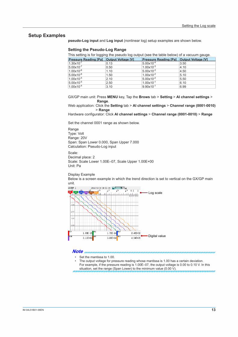
Setup Examplespseudo-Log input and Log input (nonlinear log) setup examples are shown below.
Setting the Pseudo-Log RangeThis setting is for logging the pseudo log output (see the table below) of a vacuum gauge.Pressure Reading [Pa] Output Voltage [V] Pressure Reading [Pa] Output Voltage [V]1.30x10⁻⁷ 0.13 5.00x10⁻⁴ 3.505.00x10-7 0.50 1.00x10⁻³ 4.101.00x10-6 1.10 5.00x10⁻³ 4.505.00x10-6 1.50 1.00x10⁻² 5.101.00x10-5 2.10 5.00x10⁻² 5.505.00x10-5 2.50 1.00x10⁻¹ 6.101.00x10-4 3.10 9.90x10⁻¹ 6.99
GX/GP main unit: Press MENU key, Tap the Brows tab > Setting > AI channel settings > Range.
Web application: Click the Setting tab > AI channel settings > Channel range (0001-0010) > Range
Hardware configurator: Click AI channel settings > Channel range (0001-0010) > Range
Set the channel 0001 range as shown below.
RangeType: VoltRange: 20VSpan: Span Lower 0.000, Span Upper 7.000Calculation: Pseudo-Log input
Scale:Decimal place: 2Scale: Scale Lower 1.00E‒07, Scale Upper 1.00E+00Unit: Pa
Display ExampleBelow is a screen example in which the trend direction is set to vertical on the GX/GP main unit.
Log scale
Digital value
Note• Set the mantissa to 1.00.• The output voltage for pressure reading whose mantissa is 1.00 has a certain deviation. For example, if the pressure reading is 1.00E–07, the output voltage is 0.00 to 0.10 V. In this
situation, set the range (Span Lower) to the minimum value (0.00 V).
Setting the Log scale
14 IM 04L51B01-06EN
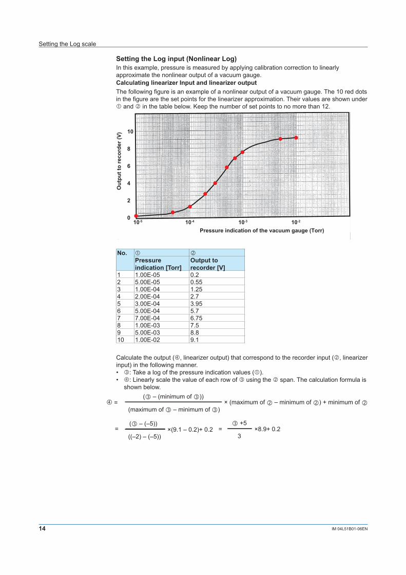
Setting the Log input (Nonlinear Log)In this example, pressure is measured by applying calibration correction to linearly approximate the nonlinear output of a vacuum gauge.Calculating linearizer Input and linearizer outputThe following figure is an example of a nonlinear output of a vacuum gauge. The 10 red dots in the figure are the set points for the linearizer approximation. Their values are shown under � and � in the table below. Keep the number of set points to no more than 12.
10
8
6
4
2
010-5 10-4 10-3 10-2
Pressure indication of the vacuum gauge (Torr)
Out
put t
o re
cord
er (V
)
No. � �Pressure indication [Torr]
Output to recorder [V]
1 1.00E-05 0.22 5.00E-05 0.553 1.00E-04 1.254 2.00E-04 2.75 3.00E-04 3.956 5.00E-04 5.77 7.00E-04 6.758 1.00E-03 7.59 5.00E-03 8.810 1.00E-02 9.1
Calculate the output (�, linearizer output) that correspond to the recorder input (�, linearizer input) in the following manner.• �: Take a log of the pressure indication values (�).• �: Linearly scale the value of each row of � using the � span. The calculation formula is
shown below.( ‒ (minimum of ))
(maximum of ‒ minimum of )× (maximum of ‒ minimum of ) + minimum of =
( ‒ (‒5))
((‒2) ‒ (‒5))×(9.1 ‒ 0.2)+ 0.2 =
+5
3×8.9+ 0.2=
Setting the Log scale
15IM 04L51B01-06EN
The combination of � and � is the set point.� � ——→ Set
point� �
log(�) Linearly scale � using �. Linearizer input [V]
Linearizer output [V]
-5 0.2 1 0.200 0.200-4.301029996 2.273611013 2 0.550 2.274-4 3.166666667 3 1.250 3.167-3.698970004 4.05972232 4 2.700 4.060-3.522878745 4.582126389 5 3.950 4.582-3.301029996 5.24027768 6 5.700 5.240-3.15490196 5.673790852 7 6.750 5.674-3 6.133333333 8 7.500 6.133-2.301029996 8.206944346 9 8.800 8.207-2 9.1 10 9.100 9.100
Setting the Channels to UseSet the channels that you want to use as follows.Setting the RangeGX/GP main unit: Press the MENU key, tap the Browse tab > Setting > AI channel
settings > RangeWeb application: Click the Setting tab > AI channel settings > Channel range (0001-0010)
> RangeHardware configurator: Click AI channel settings > Channel range (0001-0010) > Range
Item Description ExplanationMode Log input It is an input in which voltages correspond to
logarithmic values of physical values.Range 20V Range that can cover the output to recorder (�)Span 0.200 to 9.100 Minimum to the maximum of the output to recorder (�)Scale 1.00E-5 to 1.00E-2 Minimum to the maximum of the pressure indication
(�) of the vacuum gaugeDecimal place
2 Decimal place of mantissa
Unit Torr Unit of the pressure indication (�) of the vacuum gauge
Configuring calibration correctionGX/GP main unit: Press the MENU key, tap the Browse tab > Setting > AI channel
settings > Calibration correctionWeb application: Click the Setting tab > AI channel settings > Channel range (0001-0010)
> Calibration correctionHardware configurator: Click AI channel settings > Channel range (0001-0010) >
Calibration correctionItem Description ExplanationMode Linearizer
approximationCorrection type
Number of set points
10 The number of rows of � and �. If the number exceeds 12, decimate to no more than 12 while maintaining appropriate approximation.
Linearizer input
(Value) Value of �
Linearizer output
(Value) Value of �
Setting the Log scale

Blank
![] m k l Z 20176 2 21 2 log 5 1 lg2 log 3 1 Решите уравнение с помощью графиков: ) 3 3 ; )lg . Решите уравнение: )13 13 12 0; )log](https://img.pdfslide.us/doc/110x75/5eda06ab4e02a025e73dadcb/-m-k-l-z-2017-6-2-21-2-log-5-1-lg2-log-3-1-f-oe.jpg)