Embed Size (px)
Citation preview


LOCKSTITCH SOLE SEWING MACHINE MODEL DN 2000
It is important to read these instructions carefully before usingthe stitcher.
MACHINE SPEED:-
Model DN 2000 is supplied set to run at 100 stitches per minute andit is suggested that the operator should become fully conversant with themachine before the drive is adjusted to the higher speed of 160 stitchesper minute, if required.
This operation is carried out by changing belt DN 2050 onto thelarger 'V' motor pulley DN 1665 and realigning the motor pulley to ensurethat the belt is running vertical as shown on Plate 2.
STITCHING TRIALS:-
The machine's Lubricating Tank, DN 4113+ as shown on Plate 4 mustbe filled with a solution to lubricate the thread, i.e. a soluble oilmixed with water. The thread feeding from the machine base must always bewet when stitching. The shuttle thread must be waxed. The machine issupplied with a stitch sample attached. This should be removed cuttingthe thread close to the work piece. The Horn thread should be drawn throughat the same time until freshly lubricated thread is clear of the horn andthen fix under clip DN 1050, as shown on page 6, and cut off surplus thread.The shuttle thread should be left with approximately 8 - 10cm of loosethread. Scrap leather should be used in order to gain experience in theworking of the machine. To examine the stitching principle, the machinemay be operated by hand rotating the hand wheel in a clockwise direction,i.e. the top of the handwheel away from the operator when standing at thefront of the machine. Correct conditioning of the leather to be stitchedwill reduce the wear on the needle and other functioning parts.
STITCHING:-
Attach the thread under the spring clip, DN 1050 and position thebow of the horn to the left, as shown on page 6, rotate the handwheeluntil the presser foot is positioned close to the needle and using theFoot Treadle (L.H.) raise the presser foot to its upper position. Placethe work between the horn cap and the presser foot and lower to clampthe workpiece. The stitching can then proceed by operating the (R.H.)Foot Treadle and guide the work as required. The stitch length may be variedby adjustment of the stitch length control knob, DN 825S as shown on Plate 1.The presser foot tension should be adjusted when working with very softmaterials, i.e. felt or rubber etc., or with extreme thicknesses of material.This is carried out by adjustment of nuts at the top of machine, DN 832 andDN 833, as shown on Plate 10. To stop stitching release the foot treadle
-1-

and rotate the machine by hand until the needle is about to pierce theleather, turn the handwheel back one full turn and raise the presser foot.The shoe may then be removed from the machine at the same time assistingthe thread passing through the horn.
SHUTTLE:-
To remove the shuttle rotate the machine by hand until the shuttlepoint, thread splitter, and needle point are coincidental, fig 5. Loosenthe retaining screw DN 919. Rotate the shuttle retaining ring DN 918,and pull downwards. The shuttle DN 920 may then be removed. Remove thebobbin DN 927 from the shuttle using the special key DN 1114 supplied withthe machine, fig 4.
TO FIT NEW BOBBIN INTO SHUTTLE Fig 6:-
A) Pass the free end thread through the wire loop of the threader,DN 463 and draw it from inside to outside through hole ‘A’ in theshuttle wall.
B) Press the bobbin into the shuttle (the two holes in the bobbin wallto be outwards). It is advisable to place a few drops of machineoil in the housing before pressing in the bobbin. Check that thethread pulls through freely.
C) Pass the threader through the hole ‘B’ and draw the thread endthrough the hole.
D)* Position the thread behind the flat tension spring DN 930 and thethread may now be drawn through. The shuttle can now be replacedinto the machine.
E)* The shuttle thread tension can be varied by adjusting the screwDN 933.
* Only when parts are requested.
THREADING THE MACHINE Fig 1:-
The thread path through the machine is as shown on page 6. Thisis done by removing the door, DN 4075.
NEEDLE SETTING:-
When a new needle is fitted, the shank end must locate up to thestop pin DN 1011, situated inside the needle bar DN 1005, as shown onPlate 9. The hook of the needle must be directed to the right when viewedfrom the front of the machine and pointing slightly into the body of themachine. Ensure that the clamp screw DN 1014 is secure. When the needle isin its lowest position the top of the needle barb must be just below thethread hole in the whirl DN 1048, see fig 2.
-2-
-3-
WHIRL AND PINION:-
Rotate the handwheel until the shuttle tip, when travelling fromleft to right, is in line with the needle, fig 4. Rotate the horn so thatthe horn tip is facing the machine column. Remove the horn cap DN 1043, asshown on Plate 6. The hole in the whirl should be positioned as shown infig 3. It is important that if a new whirl or pinion is fitted, the engagementof the teeth is correct, this is shown in fig 2. Adjustment is made byremoving the horn tip and pinion DN 1042 and DN 1047 and adjusting the smallscrew DN 1047a situated in the end of DN 15. Only small adjustments to thisscrew should be required.
BOBBIN WINDING:-
The bobbin winder is situated on top of the base on the righthand side, as shown on Plate 1.
The cop of pre-waxed thread is positioned on the right handspool holder, DN 1530B, and the thread path to the bobbin winder is asshown on Fig 1, page 6.
Two bobbins should be positioned on to the driving spindle byremoving knob DN 4056, so that the driving pin engages into one of thetwo holes situated in the bobbin flange of the inner bobbin. Pass the freeend of the thread from inside to outside through the hole in the outerflange of the second bobbin and trap it between the outer face and the knobDN 4056. Tighten knob finger tight. Rotate the bobbin by hand 2 - 3 turnsrunning anti-clockwise, viewed from spindle end to engage the thread on thebobbin. The thread must be over the guide bar as shown on fig 1. Engagethe drive by lifting the operating lever, DN 4055 as shown on Plate 11.The thread should be ‘layed’ during the winding process to ensure eventake-off when stitching. When both bobbins are full, release the lever todisengage the drive, remove both bobbins and trim off threads. Note: Thefixed end thread on both should be trimmed as close to the flange as possible.
MAINTENANCE:-
DAILY - Oil all working faces and oil holes.WEEKLY - Apply grease to all grease nipples with grease gun.MONTHLY - Grease main countershaft, by means of grease nipple in right
hand bearing block.
RECOMMENDED THREAD AND NEEDLE SIZES:-
The machine thread must be reverse (left) twist.The machine thread should not be more than 2 sizes above the
needle size i.e. No 5.
MOTOR VOLTAGE:-
Switches are supplied to suit the motor. If the motor is changed toa different voltage the switches must also be changed.

-4-
MACHINE SETTING AND FAULT FINDING:-
Before stitching by power, a check should be made to ensure thatthe settings are correct to form the stitch. To do this, the machine shouldbe threaded up, Fig 1. Take the thread coming through the whirl and traplightly with the thumb against the horn tip (the horn’s bow should be tothe left). Turn the handwheel by hand in the direction indicated to bringthe needle down through the whirl, which will rotate, placing the thread inthe needle barb. When the needle rises, the thread is drawn through the hornand when the loop so formed gets as high as the shuttle, the thread splitterDN 928 will come across from the right and separate the threads just underthe needle point. The needle will continue to rise and the shuttle willreverse so the shuttle point, travelling from the left, will go through thegap made by the thread splitter. Then the thread lifter DN 936 will moveupwards taking the thread off the needle so that it passes around theshuttle and forms a loop around the shuttle thread. The thread leverDN 4006 will then pull the machine thread down through the horn to formthe ‘lock’. Fig 5, Page 7.
1. If the needle does not pick up the thread:- See whirl settinginstructions. See needle setting instruction (the needle could begoing down too far or not far enough, Fig 2.)
2. If the thread splitter does not divide the thread:- Check that thepoint of the thread splitter passes exactly under the point of theneedle. The thread splitter can be bent into the correct position.
3. If the thread lifter does not lift the thread from the needle:-Bend slightly up or down or move in or outwards by means of screwDN 937, Fig 5, adjusting the thread lifter so that in its highestposition the point of the thread lifter is approximately 1mm to theleft of the needle. Check that there is sufficient gap between theneedle and the thread lifter for the thread to pass.
Stitching by power can now take place. The ‘lock’ produced by thehorn thread and the shuttle should pull into the middle of the material.This can be adjusted by balancing the tension of the horn thread, by turningknob DN 4104A, Fig 1, and shuttle thread, by screw DN 933, Fig 6.
THREAD BREAKAGE:-
If the thread frays or breaks, check that there are no sharp edgeson the horn tip, the thread splitter, the thread lifter, the shuttle orneedle. Although the thread may break in the horn, it can be caused by roughedges on parts above the whirl. 90% of thread breakage is due to rough edgesdeveloping on working parts which parts which fray the thread. This must becarefully checked before the cause of breakage is sought by altering machinesettings. It is essential that the machine is allowed to feed the work andthat the operator does not push. If the work is pushed while the needle isin the work, the needle can bend and strike the horn cap damaging the needleand/or the horn cap in such a way that the thread will fray. The thread willalso fray if it is dry. Check lubricant in the container and if the machinehas been standing, pull through and remove the dry portion of the thread.
1. If the thread breaks in the machine base:- Check that the machineis threaded up correctly and that the thread is not trapped, Fig 1.

-5-
2. If the machine misses stitches:- Check whirl settings. Checkneedle settings.
3. If material does not feed:- Check that the pawl DN 809 at the backof the presser foot bar, Plate 10, is engaging correctly in theteeth of the presser foot bar. To do this, remove the front cover ofthe machine head. Do not run the machine under power when thefront cover is removed as the needle bar is then unsupported.
MACHINE IS SUPPLIED WITH THE FOLLOWING SETTINGS CORRECT. THESE SHOULDBE CHECKED.
SHUTTLE - When the shuttle point and the thread splitter DN 928 are bothat their farthest point left, the distance between the pointof the thread splitter and the needle should be 13 - 15 mm.
THREAD LEVER DN 4006 - As the needle bar DN 1005 travels downwards and thegroove on the top of the needle bar is level with the top ofbush DN 714 in the head casting, the lever DN 4006 should bejust starting its downwards movement.
PRESSER FOOT - The presser foot is fitted with screws DN 817 and DN 920,Plate 10, which can be adjusted to give correct alignment. Asingle point presser foot should be in line with the needle.When using a double point presser foot, one point should be on each sideof the needle. The presser foot must be set to clear and nottouch the horn cap.
HORN - The needle must pass through the center of the horn cap. Shouldthis be in error, check that the needle is not bent. If it isstraight, it may be corrected by adjustment of the 4 screws DN 4081Asituated in the horn base, DN 4081. Should the whirl/horn be outof square with the needle, the horn may be tipped by one or moregrub screws, DN 1035A, in the horn. The four slotted screws DN 1034must be slackened before adjusting the horn. As shown on Fig 1.

-6-

-7-

-8-

-9-

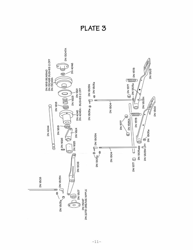
PLATE 3
DN 4044 Clutch ShaftDN 1806 Treadle LeverDN 1807 Collar for DN 1806DN 1807a Grub Screw for DN 1807DN 1625 Clutch DogDN 1626 Pin for DN 1625DN 1624 Clutch LeverDN 1618 Thrust BearingsDN 4045 Main Drive PulleyDN 1621 Pulley Clutch PadDN 1622 Screws for DN 1621DN 1623 Clutch SpringDN 13049A Clutch Shaft PulleyDN 13049b Bushes for DN 13049ADN 4046 Clutch Shaft Spacing CollarDN 13047 Clutch Shaft Bracket (R.H.)DN 13047A Clutch Shaft Bracket (L.H.)DN 13047b Screws for DN 13047 & DN 13047A to DN 4044DN 1616 Screws for DN 13047 & DN 13047ADN 2048 Grease Nipple in DN 13047DN 1808 Presser Foot Lever RodDN 13048a Screw securing 4044 to Base DN 4060
DN 1585A Treadle ShaftDN 1800 Treadle L.H. (Presser Foot)DN 1803 Treadle R.H. (Clutch)DN 1577 Collar for DN 1800 & 1803DN 1577a Screw securing DN 1577 to 1585ADN 1804 Treadle RodDN 1805N Rod End Swivel JointDN 1805a Nuts for DN 1805NDn 1578 Treadle Spring
-10-
-11-

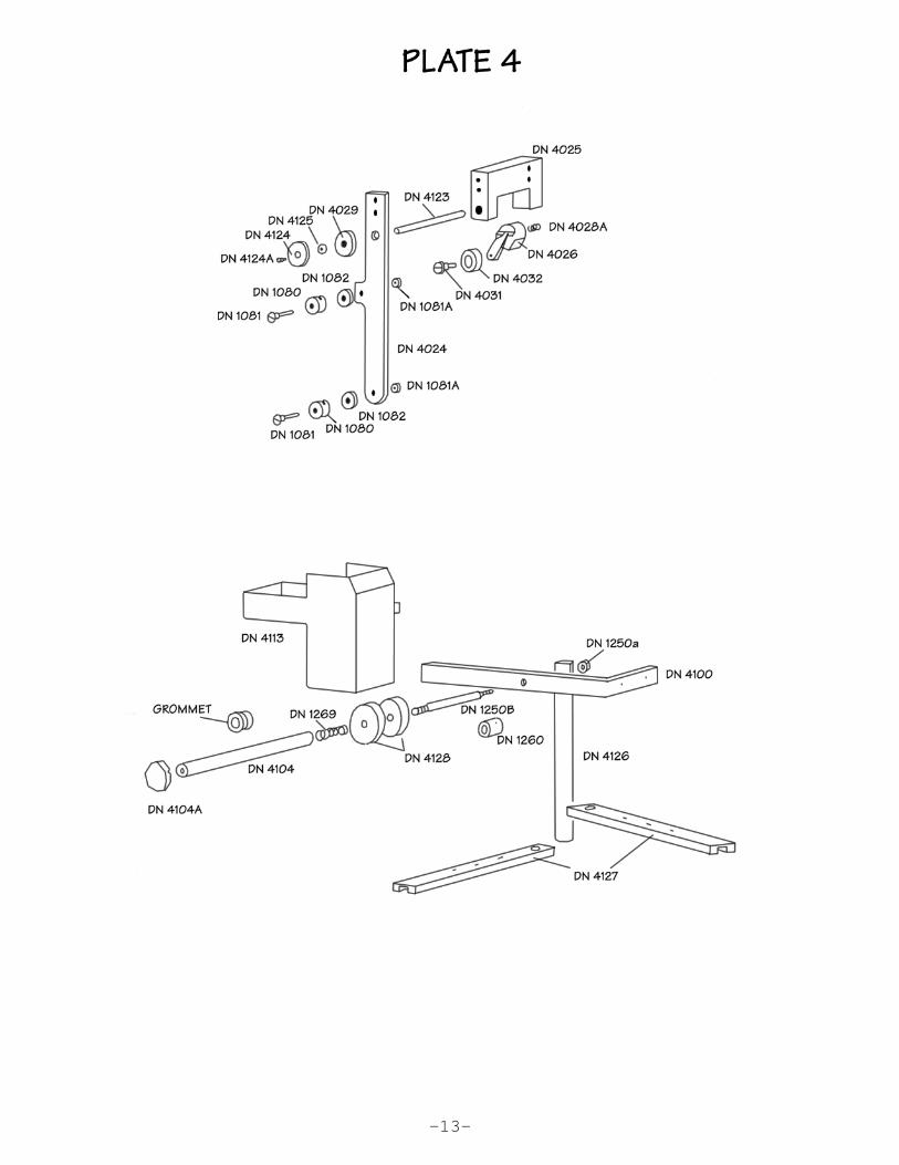
PLATE 4
DN 4024+ Thread Lock Mechanism, Front PlateDN 4025 Thread Lock Mechanism BlockDN 4025A Screws securing DN 4025 to DN 4026DN 4025B Screws securing DN 4025 to DN 4001DN 4026 Thread Lock Release LeverDN 4026A Clamp Screw in DN 4026DN 4029 Clamp Spindle SpacerDN 4028A Clamp Spindle SpringDN 4031 Cam Roller Shoulder ScrewDN 4032 Cam RollerDN 1080 Thread Roll CoverDN 1081 Thread RollDN 1081A Nut for DN 1081DN 1082 Thread RollDN 4123 Thread Lock ShaftDN 4124 Thread Lock Front Disc.DN 4125 Thread Lock RollerDN 4124A Screw securing DN 4124 to DN 4123
DN 4100 Thread Lubricating Tank SupportDN 4100a Screw for DN 4100DN 4113+ Thread Lubricating TankDN 1250B Thread Tension Disc ShaftDN 1250a Nut for DN 1250DN 4128 Thread Tension DiscsDN 1269 Thread Tension Disc SpringDN 4104 Thread Tension Knob ShaftDN 4104A Tension Shaft KnobDN 4104B Screw securing DN 4104ADN 4126 Thread Feed Arm ShaftDN 4127 Thread Feed ArmDN 4127a Screws securing DN 4127DN 1260 Disc WasherDN 1261 Screw for DN 1260
Grommet
-12-
-13-

PLATE 5
DN 4001 Front Support PlateDN 4002 Mid Mounting PlateDN 4002A Screws securing DN 4002 to DN 4001 & 4003DN 4002B Bolts securing DN 4002 to DN 4035DN 4002C Washers for DN 4002BDN 4003 Rear Support PlateDN 4005 Thread Take Up LinkDN 4006 Thread Take Up LinkDN 4007 Thread Take Up LinkDN 4008 Thread Take Up LinkDN 4009 Bottom Spur GearDN 4009A Screw for DN 4009DN 4009B Link Drive BlockDN 4009C Screw for securing DN 4009B to DN 4009DN 4010 Drive ShaftDN 4011 Bushes in DN 4001 & DN 4003DN 4012 Horn Base Driver GearDN 4013 Horn Base Driver Gear Stub ShaftDN 4013A Bush in DN 4012DN 4013B Screw securing DN 4013 to DN 4001
DN 4015 Thread Take Up Adjusting Support ArmDN 4016 Thread Take Up Adjusting PivotDN 4016A Screws securing DN 4016 to DN 4001DN 4017 Thread Take Up Bottom SpacerDN 4018 Thread Take Up Bottom Shoulder ScrewDN 4020 Mid Link Shoulder ScrewDN 4020A Mid Link Shoulder ScrewDN 4021 Top Link Shoulder ScrewDN 4022 Link SpacersDN 4023 Thread Lock CamDN 4023A Screw securing DN 4023 to DN 4009DN 4023B Nut for DN 4023ADN 730 Screw securing DN 754DN 746 Key for DN 754 & DN 4009DN 754 Bevel Gear on DN 4010DN 1080 Thread Roll CoverDN 1081 Thread Roll StudDN 1081A Nut for DN 1081DN 1082 Thread Roll
-14-

-15-
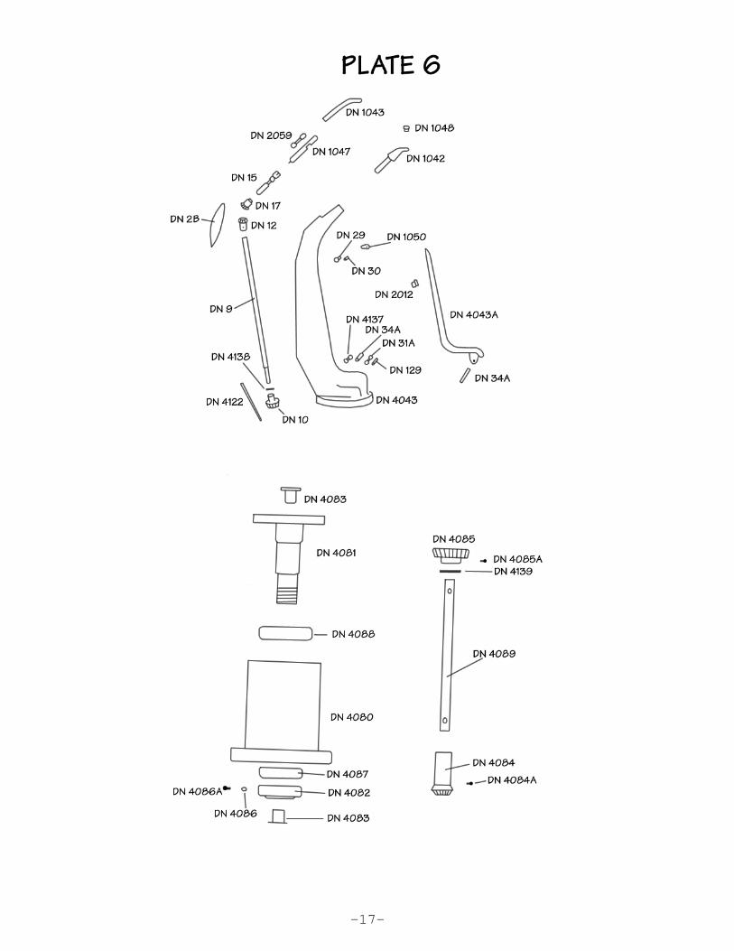
PLATE 6
DN 4043 Horn, Slim TypeDN 2059 Whirl Pinion Drive Bush.DN 1035A Horn Setting ScrewDN 1034 Horn Clamp ScrewDN 1042 Horn TipDN 1043 Horn CapDN 22 Pin for DN 1043DN 28 Screw for DN 1043DN 1044 Screw for DN 1043DN 4043A Horn Front CoverDN 4122 Horn Back CoverDN 4122A Screws for 4122DN 2B Horn Pinion CoverDN 2C Dowel for DN 2BDN 3 Screw for DN 2BDN 29 Thread Roll (upper)DN 30 Thread Roll Stud (upper)DN 2012 Horn Cover Spring ClipDN 4137 Thread Roll (lower)DN 34A Stud for DN 30 & DN 4043ADN 1050 Thread ClipDN 1051 Screw for DN 1050DN 1048 Thread WhirlDN 1047 Whirl PinionDN 15 Whirl Pinion DriveDN 1047A Screw for DN 15DN 17 Gear for DN 15DN 1045A Screw for DN 17DN 12 Whirl Drive Gear (upper)DN 10 Whirl Drive Gear (lower)DN 13 Screw for DN 12DN 1039 Pin for DN 10DN 9 Whirl Drive Gear ShaftDN 31A Thread RollDN 129 Thread Roll StudDN 4138 Washer for DN 9
DN 4080 Horn SupportDN 4081 Horn BaseDN 4081A Jacking Screws for DN 4081DN 4081B Screws securing DN 4080 to DN 4035ADN 4082 Locking RingDN 4083 Horn Base BushDN 4084 Horn Base Bottom GearDN 4084A Screws for DN 4084DN 4085 Whirl Gear Drive (upper)DN 4085A Screw for DN 4085DN 4086 Locking Screw PadDN 4086A Screw for DN 4082DN 4087 Contact Bearing (lower)DN 4088 Contact Bearing (upper)DN 4089 Main ShaftDN 4139 Washer for DN 4089
-16-
-17-

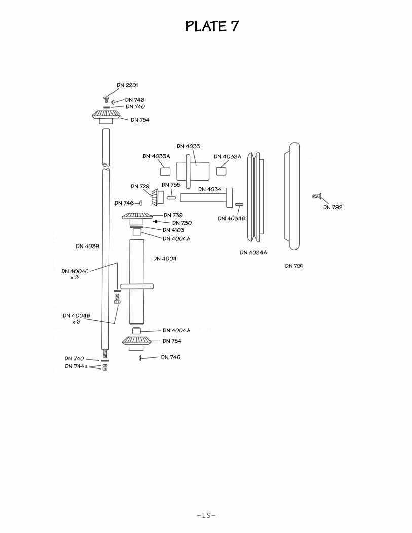
PLATE 7
DN 4039 Main Drive ShaftDN 754 Main Drive Shaft Gear (lower)DN 746 Key for DN 754DN 730 Screw securing DN 754DN 740 Gear WasherDN 744a Nuts for DN 4039DN 754 Main Drive Shaft Gear (upper)DN 746 Key for DN 754DN 754a Screw for DN 754DN 2201 Screw securing DN 754DN 4004 Main Shaft Support HousingDN 4004A Bushes for DN 4004DN 4004B Screws securing DN 4004 to 4035DN 4004C Washers for DN 4004BDN 739 Main Drive Shaft GearDN 746 Key for DN 739DN 730 Screws for DN 739DN 4103 Back Shaft Spacer
DN 4034A HandwheelDN 791 Handwheel RimDN 792 Screws securing DN 791DN 4034 Handwheel ShaftDN 4034B Pin for DN 4034ADN 755 Key for DN 4034DN 729 Handwheel GearDN 729a Screw for DN 729DN 4033 Handwheel SupportDN 4033A Bushes for DN 4033DN 4033B Screws securing DN 4033 to DN 4036
-18-
-19-

PLATE 8
DN 898 Shuttle Drive RackDN 897 Shuttle Drive ShaftDN 904 Screws securing DN 904 to DN 898DN 904a Washer for DN 904DN 903 Shaft Slide BlockDN 901 Slide Block SpacerDN 900 Slide Block FulcrumDN 900a Pin securing DN 900 to DN 897DN 905 Slide Block Retaining ScrewDN 906 Washer for DN 905DN 907 Star Washer for DN 905DN 879 Cam Lever BracketDN 879A Dowel for DN 879DN 880 Screws for DN 879DN 881 Washer for DN 879DN 881A Star Washer for DN 879
DN 885 Shuttle Drive Cam LeverDN 886 Cam Lever CarrierDN 894 Carrier EccentricDN 894W Washer for DN 894DN 893 Nut for DN 894DN 893a Washer for DN 894DN 890 Screw for DN 885DN 890a Washer for DN 885DN 887 Cam Lever Carrier PinDN 883 Screw for DN 887DN 889 Cam RollDN 888 Cam Roll Stud
DN 868 Presser Foot Cross Slide CamDN 869 Cam Lever PinDN 870 Screw for DN 869DN 872 Cam RollDN 871 Cam Roll StudDN 873 Cross-slide LeverDN 874 Lever PinDN 875 Pin for DN 874DN 778 Presser Foot Rise & Fall Cam LeverDN 778a Stop Screw for DN 778DN 778b Nut for DN 778aDN 779 Cam Lever PinDN 780 Screw for DN 779DN 784 Cam Roll StudDN 785 Cam Roll
DN 821 Cam Lever SpringDN 790 Spring Anchor in DN 702DN 788 Spring Anchor in Dn 778DN 789 Nut for DN 788DN 781 Rise & Fall LeverDN 782 Lever PinDN 783a Screw for Dn 782DN 858 Lever SpringDN 786 Spring AnchorDN 787 Screw for DN 786
-20-

-21-

-22-
PLATE 9
DN 753 MainshaftDN 754 Mainshaft Drive GearDN 755 Key for DN 754DN 730 Screw securing DN 754 to DN 753DN 762 Shuttle CamDN 763 Pin for DN 762DN 2067 Presser Foot CamDN 2067a Presser Foot Cam WasherDN 757 Needle CamDN 760 Pin for DN 757DN 746 Main Shaft Cam KeyDN 759 Needle Cam RollDN 758 Cam Roll StudDN 765 Nut for DN 758DN 765a Washer for DN 758DN 770 Mainshaft BracketDN 773 Screw for DN 770DN 772 Washers for DN 770
DN 1005 Needle BarDN 714 Needle Bar Bush (upper)DN 715 Needle Bar Bush (lower)DN 1006 Needle Bar Cam BlockDN 1009 Holding PlateDN 1010 Screws securing DN 1009 to DN 1006DN 1007 Screws securing DN 1009 to DN 1006DN 1008 Nut for DN 1007DN 1017 Washer for DN 1007DN 1016 Needle ClampDN 1015 Needle No. 6DN 1014 Screw securing DN 1016 to DN 1005DN 1011 Needle StopDN 1019 Screw for DN 1011DN 1012 Needle Bar Cam PieceDN 1013 Pins for DN 1012
DN 1813a Pawl (upper)DN 1814 Pawl (lower)DN 847 Pawl BlockDN 848 Screws for DN 847DN 1821 Pawl SpringDN 1815 Pawl Slide PieceDN 1816 SpacerDN 1817 Pawl Cam PieceDN 1818 Screws for 1817DN 1819 Washers for 1817DN 1825 Washers for DN 1817DN 1823 Pawl Setting PieceDN 1824 Screw for DN 1824DN 1825 Washer for 1824DN 1826 Star Washers for DN 1824DN 1822 Pawl Stud

-23-

-24-
PLATE 10
DN 816 Presser Foot (serrated)DN 817 Presser Foot Setting Screw (Horizontal)DN 820 Presser Foot Setting Screw (Vertical)DN 819 Screw for DN 816DN 819a Washer for DN 816DN 804 Presser Foot BarDN 799 Presser Foot Bar CarrierDN 801 Screw securing DN 800 to DN 799DN 802 Washer for DN 801DN 809 Presser Foot Bar PawlDN 822 Pin for DN 809DN 823 Screw for DN 822DN 808 Pawl BlockDN 1820 Pawl Cam PieceDN 1820a Washer for DN 1820DN 814 Screw for DN 1820DN 805 Pawl Release CamDN 807 Screws for DN 805DN 807a Washer for DN 805DN 803 Presser Foot SpringDN 812 Presser Foot Spring Pin in DN 800DN 810 Presser Foot Spring Pin in DN 809DN 834 Presser Foot Spring AnchorDN 833 Spring Anchor NutDN 832 Locknut for DN 833DN 832a Washer for DN 833DN 830 Spring Anchor PlateDN 831 Screws for DN 830DN 811 Pivot PinDN 795 Presser Foot ShaftDN 798 Presser Foot Shaft SpringDN 2048 Shaft Greaser
DN 920 ShuttleDN 908/909 Shuttle Driver/ShaftDN 910 Shuttle Driver GearDN 911 Pins for DN 909 & DN 910DN 915 Shuttle HolderDN 916 Screw securing DN 915DN 918 Shuttle HousingDN 917 Pin in DN 918DN 919 Housing Clamp ScrewDN 928 Thread SplitterDN 929 Screw for DN 928DN 936 Thread Lifter
DN 935 Thread Lifter Lever StudDN 934 Thread Lifter LeverDN 937 Screw for DN 936DN 940 Cam Roll StudDN 941 Thread Lifter Lever Cam RollDN 942 Spring AnchorDN 943 Thread Lifter Lever SpringDN 927 Bobbin

-25-
-26-
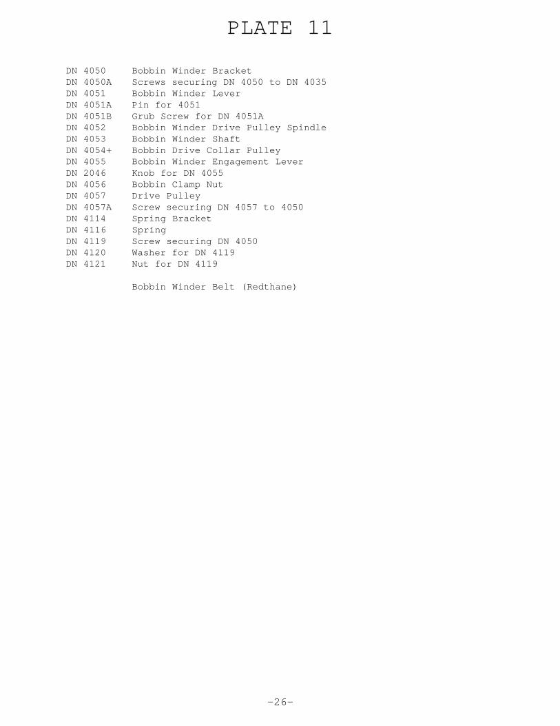
PLATE 11
DN 4050 Bobbin Winder BracketDN 4050A Screws securing DN 4050 to DN 4035DN 4051 Bobbin Winder LeverDN 4051A Pin for 4051DN 4051B Grub Screw for DN 4051ADN 4052 Bobbin Winder Drive Pulley SpindleDN 4053 Bobbin Winder ShaftDN 4054+ Bobbin Drive Collar PulleyDN 4055 Bobbin Winder Engagement LeverDN 2046 Knob for DN 4055DN 4056 Bobbin Clamp NutDN 4057 Drive PulleyDN 4057A Screw securing DN 4057 to 4050DN 4114 Spring BracketDN 4116 SpringDN 4119 Screw securing DN 4050DN 4120 Washer for DN 4119DN 4121 Nut for DN 4119
Bobbin Winder Belt (Redthane)

-27-


![1-NEEDLE LOCKSTITCH SEWING MACHINE WITH AUTOMATIC …€¦ · 1-NEEDLE LOCKSTITCH SEWING MACHINE WITH AUTOMATIC THREAD TRIMMER FOR PROFESSIONAL No.00 40175681. CONTENTS [1] SPECIFICATIONS](https://img.pdfslide.us/doc/110x75/6071735a1556115d42165cf8/1-needle-lockstitch-sewing-machine-with-automatic-1-needle-lockstitch-sewing-machine.jpg)


![1-NEEDLE LOCKSTITCH SEWING MACHINE WITH ... LOCKSTITCH SEWING MACHINE WITH AUTOMATIC THREAD TRIMMER FOR PROFESSIONAL C O N T E N T S [1] SPECIFICATIONS OF TL-98P/98Q.....1 [2] NAMES](https://img.pdfslide.us/doc/110x75/5aaf8a357f8b9a07498d7719/1-needle-lockstitch-sewing-machine-with-lockstitch-sewing-machine-with-automatic.jpg)