Embed Size (px)
Citation preview

Lockout / Tagout Safety Program
Prepared by: The Ohio State University
Environmental Health and Safety Occupational Safety & Industrial Hygiene
1314 Kinnear Road
Columbus, OH 43212-1168
614-292-1284 Phone 614-292-6404 Fax
www.ehs.osu.edu
Page 2
Revised 2018
Table of Contents
Introduction ......................................................................................................................................................... 3
Responsibilities .................................................................................................................................................. 3
Definitions ........................................................................................................................................................... 4
Lockout/Tagout Devices .................................................................................................................................... 6
LOTO Application and Exemptions .................................................................................................................. 9
Individual LOTO Procedures ............................................................................................................................. 10
Group LOTO Procedures ................................................................................................................................... 12
Removal of a LOTO Device in an Employee Absence .................................................................................... 13
Training and Recordkeeping ............................................................................................................................. 14
Periodic Inspection............................................................................................................................................. 15
Appendix A – LOTO Functional Flow Diagram ................................................................................................ 16 Appendix B – Sample Written LOTO Procedure ............................................................................................. 17 Appendix C – Equipment LOTO Work Plan ..................................................................................................... 18 Appendix D – Energy Source Determination ................................................................................................... 19 Appendix E – Employees Authorized to Perform Lockout/Tagout Operations ........................................... 22 Appendix F – Hazardous Energy Control Program Evaluation and Certification Form .............................. 23 Appendix G – Wexner Medical Center Specifications…………………………………………………………….24
Page 3
Revised 2018
1.0 Introduction
1.1 In order to prevent death, injuries and property loss, all employees, students, contractors and visitors of The Ohio State University must comply with the requirements of the Control of Hazardous Energy Standard (OSHA 29CFR 1910.147 and 1910.269), commonly referred to as Lockout/Tagout (LOTO) standards.
1.2 This policy establishes requirements for the lockout of energy-isolating devices. The intent is to ensure that equipment is de-energized and isolated from all potentially hazardous energy sources and locked out before employees perform service or maintenance tasks where the unexpected energizing, start-up, or release of stored energy could cause injury.
1.3 Authorized employees are required to perform LOTO in accordance with the policies and procedures established herein. All other, non-authorized employees observing equipment that is locked out shall not attempt to start-up, energize, use the equipment, tamper with or remove the LOTO device. Failure to comply with the provisions of this program may result in corrective action, up to and including termination.
2.0 Responsibilities
2.1 OSU Environmental Health & Safety - The Ohio State University Office of Environmental Health & Safety (EHS) is responsible for the following:
2.1.1 Updates and revisions to the written Lockout/Tagout Safety Program;
2.1.2 Provide program oversight and a resource to implementing departments.
2.2 Department Supervisors – Supervisors or department heads of areas where lockout/tagout is utilized are responsible for the following:
2.2.1 Conduct periodic evaluations of the LOTO program in place to ensure it meets all applicable requirements.
2.2.2 Ensure affected employees have been properly trained in all applicable areas of LOTO.
2.2.3 Maintain a list of authorized employees who may perform LOTO procedures.
2.2.4 Provide sufficient locks and/or tags for the LOTO procedures being conducted.
2.2.5 Develop equipment specific LOTO procedures for each type of equipment.
2.3 Affected Employees - Those employees who may work with equipment on which LOTO devices are used are responsible for the following:
2.3.1 Do not attempt to operate or energize any energy-isolating device that is under LOTO.

Page 4
Revised 2018
2.3.2 Do not tamper with any lockout device or tag.
2.3.3 Report any violations of this policy to their supervisor.
2.4 Authorized Employees – Those employees who may have be responsible for applying LOTO devices and working on de-energized equipment are responsible for the following:
2.4.1 Properly identify and perform LOTO on all hazardous energy sources.
2.4.2 Notify affected employees that LOTO activities will be conducted.
2.4.3 Follow specific LOTO procedures for equipment and machinery.
2.4.4 Report violations to their supervisor.
2.5 Contractors – non-OSU personnel who are working on projects associated with OSU LOTO are responsible for the following:
2.5.1 Be provided and aware of the OSU LOTO Safety Program.
2.5.2 Ensure project/building management is aware of any LOTO being performed as part of contractor work.
2.5.3 Ensure contractor employees comply with all applicable OSHA LOTO requirements.
3.0 Definitions
Affected Employee - The employee whose job requires the operation or use of a machine or equipment on which servicing or maintenance is being performed under LOTO, or whose job requires him/her to work in an area in which such servicing or maintenance is being performed.
Authorized Employee - An employee who has received the proper training and has been “authorized” by their department to apply LOTO devices when necessary to LOTO hazardous energy sources to perform service or maintenance.
Capable of being Locked Out - An energy-isolating device that is designed with a hasp or other means of attachment to which or through which a lock can be affixed, or has a locking mechanism built into it. Other energy-isolating devices also will be considered to be capable of being locked out, if lockout can be achieved without the need to dismantle, rebuild, or replace the energy-isolating device or permanently alter its energy control capability.
Caution Tag - A warning device such as a tag with means of attachment used to warn employees of an existing or potential hazard. Its legend cautions personnel of the hazard(s) and identifies the employee who attached the tag.
Energized – Connected to an energy source or containing residual or stored energy.
Energy-Isolating Device - A mechanical device that physically prevents the transmission or release of energy, including but not limited to a manually operated electrical circuit breaker, a disconnect switch; a manually operated switch by which the conductors of a circuit can be disconnected from all ungrounded supply
Page 5
Revised 2018
conductors and no pole can be operated independently; a line valve; a block; any similar device used to block or isolate energy. The term does not include push button, selector switch, or other control type devices.
Energy Source – Any source of electrical, mechanical, hydraulic, pneumatic, chemical, thermal or other energy.
Hazard – A source of possible injury or damage to health
Hot Tap – A procedure used in the repair, maintenance and services activities, which involves welding on a piece of equipment (pipelines, vessels or tanks) under pressure, in order to install connections or appurtenances. Commonly used to replace or add sections of pipeline without interruption of service for air, gas, water, steam and petrochemical distribution systems.
Lockout - The placement of a lockout device on an energy-isolating device, in accordance with an established procedure, to ensure that the energy-isolating device and the equipment being controlled cannot be operated until the lockout device is removed.
Lockout Box - A lockable storage box capable of securing keys to lockout devices
Lockout Device - A device that utilizes an affirmative means such as tags, locks, hasps, chains, and other hardware to secure an energy-isolating device in a safe position and prevent the operation or energizing of hazardous energy sources.
Lockout Form - A preprinted form to fill out for group LOTO procedure to document and communicate isolation and repair status
Lockout/Tagout – Specific practices and procedures to safeguard employees from the unexpected energizing or start-up of machinery and equipment or the release of hazardous energy during service or maintenance activities.
LOTO – An acronym for Lockout/Tagout.
LOTO, Group – Type of lockout procedure used for multiple workers, work groups, and/or work shifts
LOTO, Individual - Type of lockout procedure used where one individual has total responsibility for the lockout and repair
LOTO Release - Process of removing all locks, tags, and devices for the purpose of testing.
Other Employee - An employee whose job requires them to work in an area where service or maintenance is being performed in conjunction with a hazardous energy source.
Owner/Operator – Responsible person for the operation, shutdown, and start-up of equipment to be locked out. May have responsibility for the equipment maintenance and repair.
PPE – Personal protective equipment
Risk – Refers to a combination of both the likelihood of injury occurrence and the severity
Page 6
Revised 2018
Setting up – Any work performed to prepare a machine or equipment to perform its normal production operation.
Servicing/Maintenance - Workplace activities such as constructing, installing, setting up, adjusting, inspecting, modifying, and maintaining machines or equipment. These activities include lubricating, cleaning, or un-jamming machines or equipment and making adjustments to tools where the employee may be exposed to the unexpected energizing or release of hazardous energy.
Supervisor - Responsible person for the service group working on equipment when the group performing the service work is different from the owner/operator.
Tagout - The placement of a tagout device on an energy-isolating device, in accordance with an established procedure, to indicate that the energy-isolating device and equipment being controlled may not be operated until the tagout device is removed. When tagout procedures are utilized, additional safety practices will be required such as removing fuses, etc. A tag is only a warning device
4.0 Lockout/Tagout Devices
4.1 Standardized Devices
4.1.1 LOTO devices must be standardized, identified as such, and used only for the LOTO program within the department. All other uses of LOTO devices are prohibited.
4.1.2 Lockout and tagout devices shall indicate the identity of the employee applying the device(s).
4.1.3 The lockout devices must be uniquely identified in at least one of the following criteria:
4.1.3.1 Color
4.1.3.2 Shape
4.1.3.3 Size
4.1.4 In the case of tagout devices, print and format must be standardized.
4.2 Durable locks and tags
4.2.1 LOTO devices shall be capable of withstanding the environment to which they are exposed for the maximum period of time that exposure is expected.
4.2.2 Lockout devices must be substantial enough to prevent removal without the use of excessive force or unusual techniques, such as the use of bolt cutters or other metal cutting tools.
4.2.3 Tagout devices must be substantial enough to prevent inadvertent or accidental removal.
4.2.4 Tagout devices must be non-reusable, attached by hand, self-locking and non-releasable with a minimum unlocking strength of not less than 50 pounds.
Page 7
Revised 2018
4.2.5 Tagout devices also need to have the general design and basic characteristics of being at least equivalent to a one-piece, all environment-tolerant nylon cable tie (see Table 1).
4.2.6 Tagout devices shall be constructed and printed so that exposure to weather conditions or wet and damp locations will not cause the tag to deteriorate or the message on the tag to become illegible.
4.2.7 Tags shall not deteriorate when used in corrosive environments such as areas where acid and alkali chemicals are handled and stored.
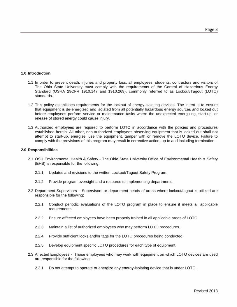
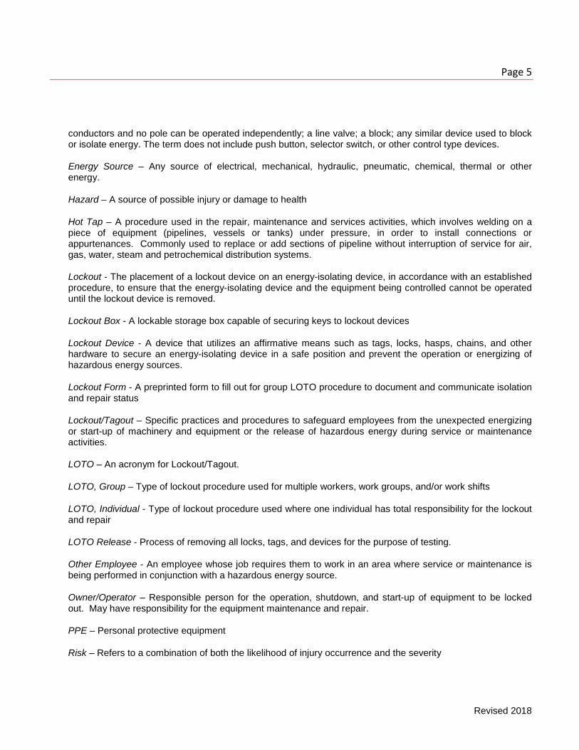
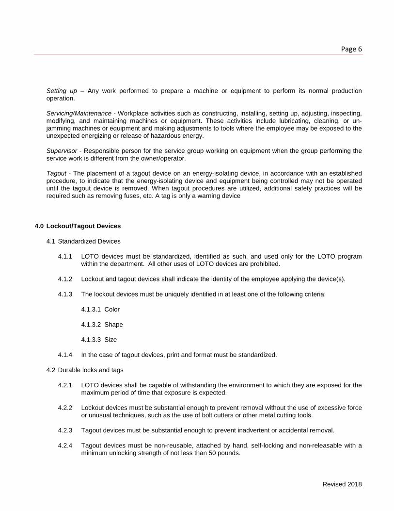
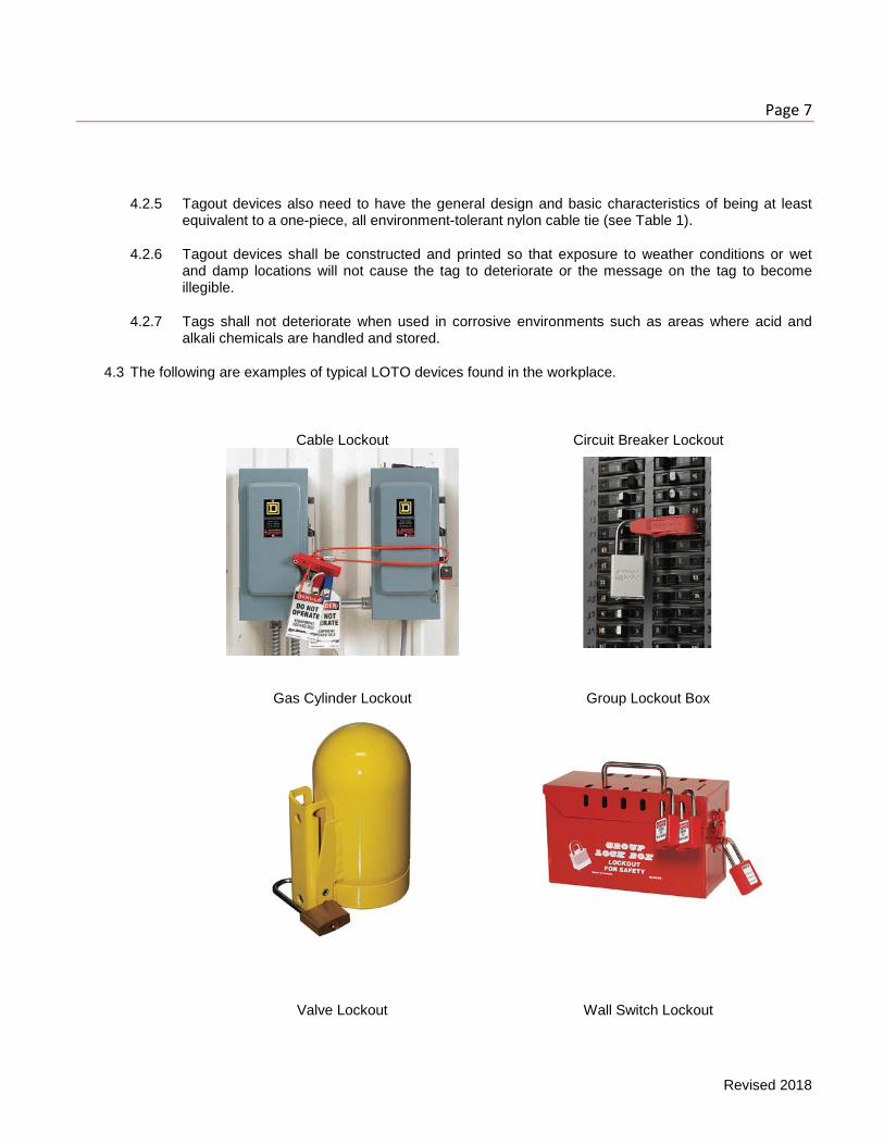
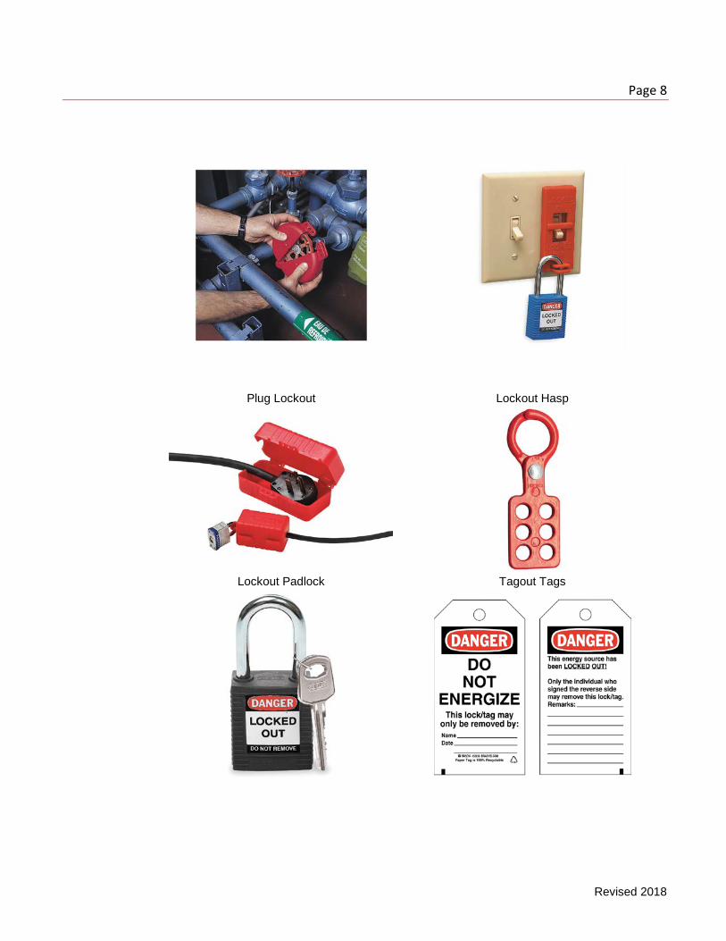
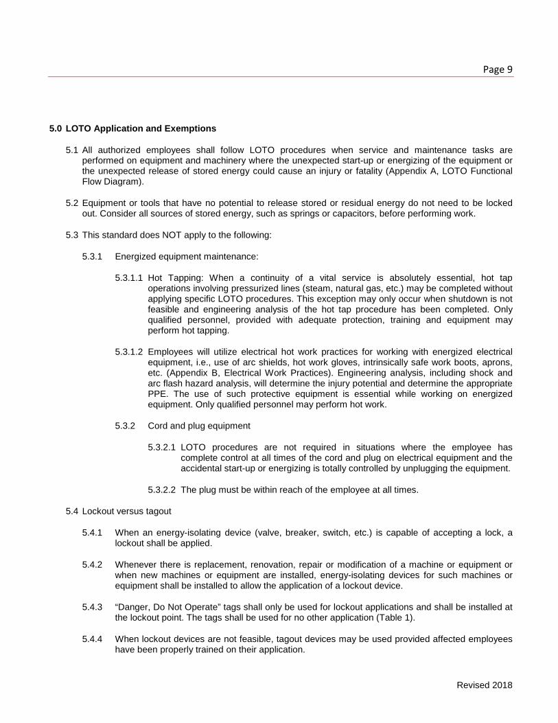
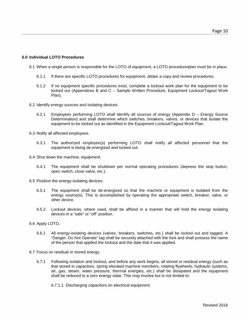
4.3 The following are examples of typical LOTO devices found in the workplace.
Cable Lockout Circuit Breaker Lockout
Gas Cylinder Lockout Group Lockout Box
Valve Lockout Wall Switch Lockout
Page 8
Revised 2018
Plug Lockout Lockout Hasp
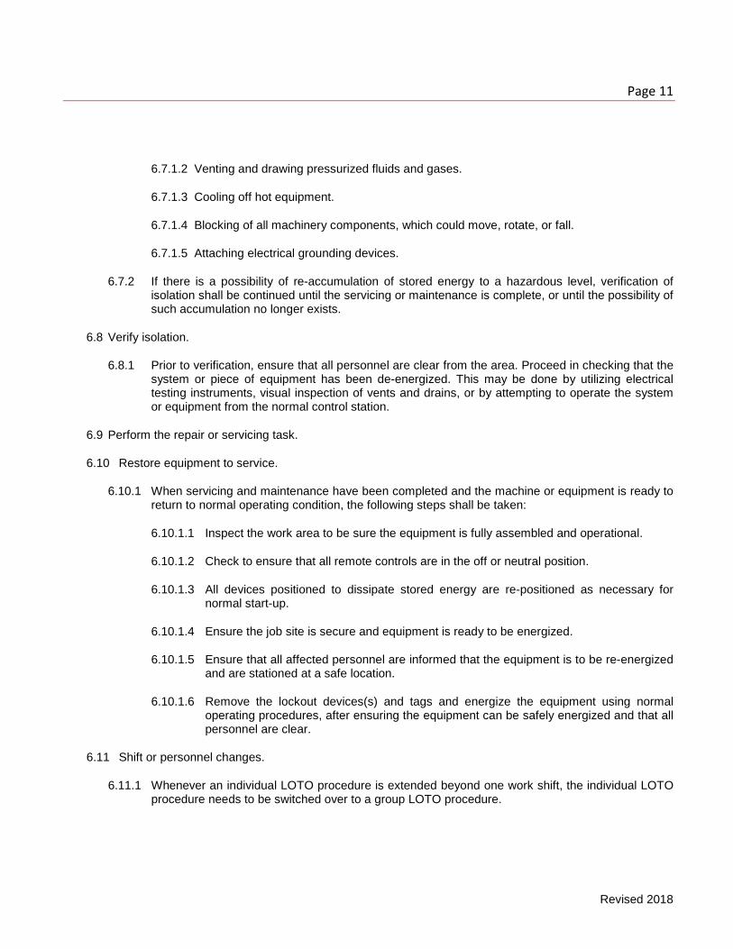
Lockout Padlock Tagout Tags
Page 9
Revised 2018
5.0 LOTO Application and Exemptions
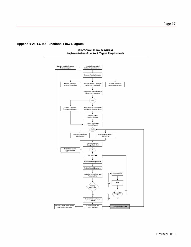
5.1 All authorized employees shall follow LOTO procedures when service and maintenance tasks are performed on equipment and machinery where the unexpected start-up or energizing of the equipment or the unexpected release of stored energy could cause an injury or fatality (Appendix A, LOTO Functional Flow Diagram).
5.2 Equipment or tools that have no potential to release stored or residual energy do not need to be locked out. Consider all sources of stored energy, such as springs or capacitors, before performing work.
5.3 This standard does NOT apply to the following:
5.3.1 Energized equipment maintenance:
5.3.1.1 Hot Tapping: When a continuity of a vital service is absolutely essential, hot tap operations involving pressurized lines (steam, natural gas, etc.) may be completed without applying specific LOTO procedures. This exception may only occur when shutdown is not feasible and engineering analysis of the hot tap procedure has been completed. Only qualified personnel, provided with adequate protection, training and equipment may perform hot tapping.
5.3.1.2 Employees will utilize electrical hot work practices for working with energized electrical equipment, i.e., use of arc shields, hot work gloves, intrinsically safe work boots, aprons, etc. (Appendix B, Electrical Work Practices). Engineering analysis, including shock and arc flash hazard analysis, will determine the injury potential and determine the appropriate PPE. The use of such protective equipment is essential while working on energized equipment. Only qualified personnel may perform hot work.
5.3.2 Cord and plug equipment
5.3.2.1 LOTO procedures are not required in situations where the employee has complete control at all times of the cord and plug on electrical equipment and the accidental start-up or energizing is totally controlled by unplugging the equipment.
5.3.2.2 The plug must be within reach of the employee at all times.
5.4 Lockout versus tagout
5.4.1 When an energy-isolating device (valve, breaker, switch, etc.) is capable of accepting a lock, a lockout shall be applied.
5.4.2 Whenever there is replacement, renovation, repair or modification of a machine or equipment or when new machines or equipment are installed, energy-isolating devices for such machines or equipment shall be installed to allow the application of a lockout device.
5.4.3 “Danger, Do Not Operate” tags shall only be used for lockout applications and shall be installed at the lockout point. The tags shall be used for no other application (Table 1).
5.4.4 When lockout devices are not feasible, tagout devices may be used provided affected employees have been properly trained on their application.
Page 10
Revised 2018
6.0 Individual LOTO Procedures
6.1 When a single person is responsible for the LOTO of equipment, a LOTO procedure/plan must be in place.
6.1.1 If there are specific LOTO procedures for equipment, obtain a copy and review procedures.
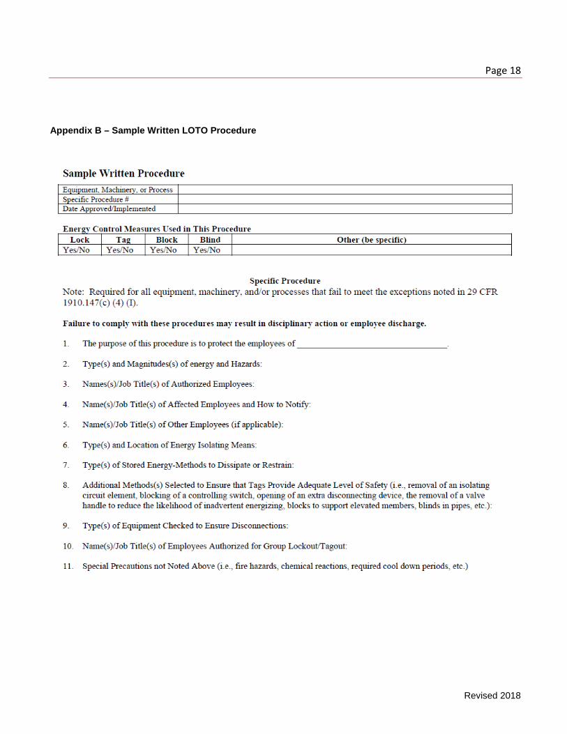
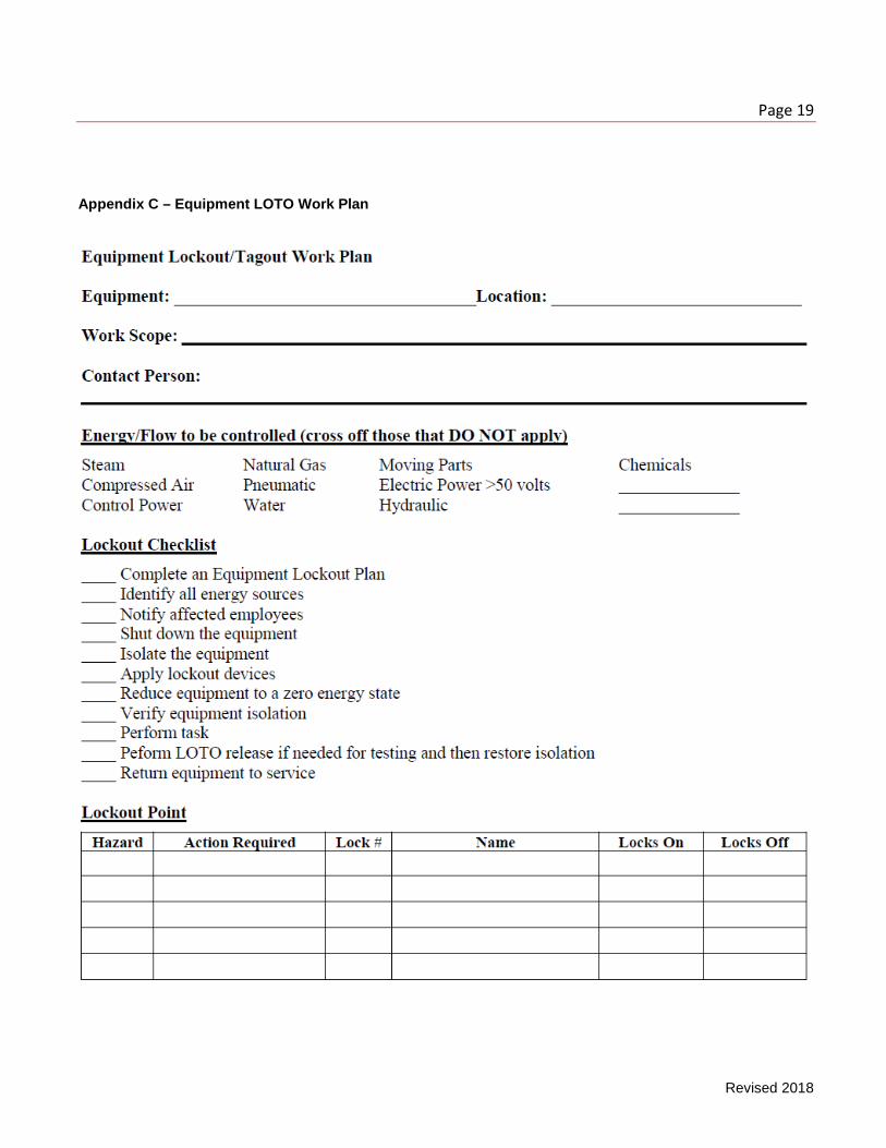
6.1.2 If no equipment specific procedures exist, complete a lockout work plan for the equipment to be locked out (Appendices B and C – Sample Written Procedure, Equipment Lockout/Tagout Work Plan).
6.2 Identify energy sources and isolating devices:
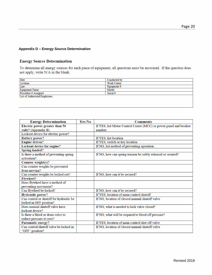
6.2.1 Employees performing LOTO shall identify all sources of energy (Appendix D – Energy Source Determination) and shall determine which switches, breakers, valves, or devices that isolate the equipment to be locked out as identified in the Equipment Lockout/Tagout Work Plan.
6.3 Notify all affected employees.
6.3.1 The authorized employee(s) performing LOTO shall notify all affected personnel that the equipment is being de-energized and locked out.
6.4 Shut down the machine, equipment.
6.4.1 The equipment shall be shutdown per normal operating procedures (depress the stop button, open switch, close valve, etc.).
6.5 Position the energy-isolating devices.
6.5.1 The equipment shall be de-energized so that the machine or equipment is isolated from the energy source(s). This is accomplished by operating the appropriate switch, breaker, valve, or other device.
6.5.2 Lockout devices, where used, shall be affixed in a manner that will hold the energy isolating devices in a “safe” or “off” position.
6.6 Apply LOTO.
6.6.1 All energy-isolating devices (valves, breakers, switches, etc.) shall be locked out and tagged. A “Danger, Do Not Operate” tag shall be securely attached with the lock and shall possess the name of the person that applied the lockout and the date that it was applied.
6.7 Focus on residual or stored energy.
6.7.1 Following isolation and lockout, and before any work begins, all stored or residual energy (such as that stored in capacitors, spring elevated machine members, rotating flywheels, hydraulic systems, air, gas, steam, water pressure, thermal energies, etc.) shall be dissipated and the equipment shall be reduced to a zero energy state. This may involve but is not limited to:
6.7.1.1 Discharging capacitors on electrical equipment.
Page 11
Revised 2018
6.7.1.2 Venting and drawing pressurized fluids and gases.
6.7.1.3 Cooling off hot equipment.
6.7.1.4 Blocking of all machinery components, which could move, rotate, or fall.
6.7.1.5 Attaching electrical grounding devices.
6.7.2 If there is a possibility of re-accumulation of stored energy to a hazardous level, verification of isolation shall be continued until the servicing or maintenance is complete, or until the possibility of such accumulation no longer exists.
6.8 Verify isolation.
6.8.1 Prior to verification, ensure that all personnel are clear from the area. Proceed in checking that the system or piece of equipment has been de-energized. This may be done by utilizing electrical testing instruments, visual inspection of vents and drains, or by attempting to operate the system or equipment from the normal control station.
6.9 Perform the repair or servicing task.
6.10 Restore equipment to service.
6.10.1 When servicing and maintenance have been completed and the machine or equipment is ready to return to normal operating condition, the following steps shall be taken:
6.10.1.1 Inspect the work area to be sure the equipment is fully assembled and operational.
6.10.1.2 Check to ensure that all remote controls are in the off or neutral position.
6.10.1.3 All devices positioned to dissipate stored energy are re-positioned as necessary for normal start-up.
6.10.1.4 Ensure the job site is secure and equipment is ready to be energized.
6.10.1.5 Ensure that all affected personnel are informed that the equipment is to be re-energized and are stationed at a safe location.
6.10.1.6 Remove the lockout devices(s) and tags and energize the equipment using normal operating procedures, after ensuring the equipment can be safely energized and that all personnel are clear.
6.11 Shift or personnel changes.
6.11.1 Whenever an individual LOTO procedure is extended beyond one work shift, the individual LOTO procedure needs to be switched over to a group LOTO procedure.
Page 12
Revised 2018
7.0 Group LOTO Procedures
7.1 Group LOTO is used whenever multiple repair workers and/or work shifts are involved.
7.2 When maintenance work is performed by contractors or by work groups different than the group that operates the equipment, information exchange must occur to ensure that all parties are aware of the LOTO status of equipment/machines.
7.3 Group LOTO follows all the requirements of individual LOTO procedures listed above in addition to:
7.3.1 A primary owner/operator will be designated. This employee will exercise primary responsibility for implementation of the LOTO procedure for the equipment and machinery to be serviced. The primary owner/operator will coordinate operations with equipment operators before and after LOTO.
7.3.2 The authorized employee is the coordinator for the project.
7.3.3 A verification system must be implemented to ensure the continued isolation and de-energizing of hazardous energy sources during maintenance and service operations. Typically this will involve the use of a LOTO work plan (Appendix C) and a lock box to store the keys to locks on all energy-isolation devices. Once isolated, all keys are placed in the lock box and the primary owner/operator will place a lock on the lock box containing the LOTO keys.
7.3.4 Each authorized employee working on the equipment shall individually verify that hazardous energy has been isolated and de-energized and place an individual lock on the lock box.
7.3.5 When more than one crew or trades craft is involved, a principal authorized employee who is responsible for the service repair group is designated. The service group supervisor will place a service supervisor lock on the group lock box and store the key in a mutually agreeable location.
7.3.6 Use LOTO release any time the lockout box needs to be opened during the servicing work, such as testing motor rotation. Clear all workers from the equipment and worker locks off the lock box. When release is complete, restore isolation of energy sources.
7.3.7 Once servicing work is complete, all workers will remove their individual locks and tags. The servicing supervisor will inspect the work site and equipment and then remove their lock from the lock box and sign off on the LOTO form.
7.3.8 Specific written procedures must be developed and implemented for complex isolation systems or repair operations involving many workers over more than one work shift.
Page 13
Revised 2018
8.0 Tagout Procedures
8.1 Because of design characteristics of certain equipment, a lockout device is not always feasible. Whenever a tagout is independently used for the control of hazardous energy, the following steps shall be taken:
8.1.1 The tagout must be accomplished by a completed LOTO procedure work plan, which states that a tagout will be used.
8.1.2 Tagout must comply with basic LOTO procedures.
8.1.3 Tags shall be affixed at the same location that a lock would have been attached.
8.1.4 Affected employees will be trained and made aware of the use of tags.
8.1.5 It must be emphasized that tags are only warning devices.
8.1.6 Acceptable methods of isolating equipment being tagged out include:
8.1.6.1 Removal of an isolating circuit breaker.
8.1.6.2 Blocking of a control switch.
8.1.6.3 Opening a second disconnecting device.
8.1.6.4 Removal of a valve handle.
8.2 Whenever tagout is used, additional safety precautions should be taken to isolate equipment and to prevent energizing the equipment.
8.3 A tagout shall only be used when the design of equipment or machinery makes it unfeasible to utilize a lockout device.
8.4 Tagout devices, where used, shall be affixed in a manner that will hold the energy isolating devices in a “safe” or “off” position.
8.4.1 Where a tag cannot be affixed directly to the energy isolating device, the tag shall be located as close as safely possible to the device, in a position that will be immediately obvious to anyone attempting to operate the device.
9.0 Removal of a LOTO Device in an Employee Absence
9.1 Removal of a lockout device in the case of the employee who applied the device being absent:
9.1.1 Verify the employee is not on the premises.
9.1.2 Attempt to contact the employee to verify job/equipment status.
9.1.3 Verify that the equipment can be safely energized.
Page 14
Revised 2018
9.1.4 Record on the lockout form that the person’s lockout device was removed.
9.1.5 Inform the employee upon return that their lockout device was removed.
9.2 Each department/area will be responsible for developing and implementing specific procedures for all special situations.
10.0 Training and Recordkeeping
10.1 Training on the purpose, content and function of the LOTO policy is required for all employees who participate in or are affected by the LOTO of equipment. Training can be obtained through EHS and/or through department-specific training. Records must be kept showing training dates, attendance, items covered, and name of presenter.
10.2 Authorized Employees
10.2.1 Authorized employees are those who have received proper training and have been “authorized” by their department to apply LOTO devices when necessary. Training for authorized employees shall include:
10.2.1.1 The recognition and identification of potential hazardous and stored energy sources in the work area or department.
10.2.1.2 Explanation and proper use of LOTO procedures.
10.2.1.3 Proper use, application and removal of LOTO devices and systems.
10.2.1.4 Specific area equipment LOTO procedures.
10.2.1.5 How to deal with special conditions.
10.3 Affected Employees
10.3.1 Affected Employees are those whose job requires the operation or use of a machine or equipment on which servicing or maintenance is being performed under LOTO. Training for affected employees shall include:
10.3.1.1 Purpose and use of the LOTO procedures.
10.3.1.2 How to recognize LOTO equipment.
10.3.1.3 Prohibition on tampering with LOTO equipment.
10.4 Retraining
10.4.1 Retraining or additional training is required whenever:
10.4.1.1 There is a new or revised energy control procedure.
10.4.1.2 An authorized employee's job duties change regarding LOTO.
Page 15
Revised 2018
10.4.1.3 The LOTO Program changes.
10.4.1.4 Additional unique LOTO hazards arise, such as new equipment, modified processes, or the use of different LOTO devices.
10.4.1.5 Periodic inspections or program evaluations show employee deficiencies in LOTO techniques.
10.4.1.6 Tri-annual refresher training is due.
10.5 Annual Program Evaluation
10.5.1 Program evaluation shall be made periodically and at a minimum once per year. The evaluation will be made by management personnel of randomly selected authorized employees or supervisors to ensure that LOTO procedures are followed. The evaluation will include a field inspection and be recorded on a standardized Hazardous Energy Control Program Evaluation and Certification Form (Appendix E). If deficiencies are identified, the program will be reviewed and modified as required. Once per year an Administrative Review will be completed by an EHS representative for the area and reviewed with the appropriate director.
10.6 Recordkeeping
10.6.1 All records applicable to the Hazardous Energy Control Program shall be maintained on file for five (5) years. Records shall include:
10.6.1.1 Training session outlines.
10.6.1.2 Training attendance sheets.
10.6.1.3 Training exam scores.
10.6.1.4 Completed LOTO forms.
10.6.1.5 Program evaluation forms.
10.6.1.6 List of authorized employees.
10.6.1.7 Annual administrative reviews.
10.6.1.8 Action plans and follow-up from evaluations and reviews.
11.0 Periodic Inspection
11.1 A periodic inspection of the energy control procedure shall be conducted at least annually to ensure that the LOTO requirements are being followed.
11.2 The periodic inspection shall be performed by an authorized employee other than the ones(s) utilizing the energy control procedure being inspected.
Page 16
Revised 2018
11.3 The periodic inspection shall be conducted to correct any deviations or inadequacies identified. 11.4 Where lockout is used for energy control, the periodic inspection shall include a review, between
the inspector and each authorized employee, of that employee's responsibilities under the energy control procedure being inspected.
11.5 Where tagout is used for energy control, the periodic inspection shall include a review, between
the inspector and each authorized and affected employee, of that employee's responsibilities under the energy control procedure being inspected.
11.6 The employer shall certify that the periodic inspections have been performed. The certification
shall identify the machine or equipment on which the energy control procedure was being utilized, the date of the inspection, the employees included in the inspection, and the person performing the inspection.
Page 17
Revised 2018
Appendix A: LOTO Functional Flow Diagram
Page 18
Revised 2018
Appendix B – Sample Written LOTO Procedure
Page 19
Revised 2018
Appendix C – Equipment LOTO Work Plan
Page 20
Revised 2018
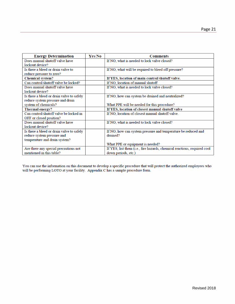
Appendix D – Energy Source Determination
Page 21
Revised 2018

Page 22
Revised 2018
Appendix E – Hazardous Energy Control Program Evaluation and Certification Form
Page 23
Revised 2018
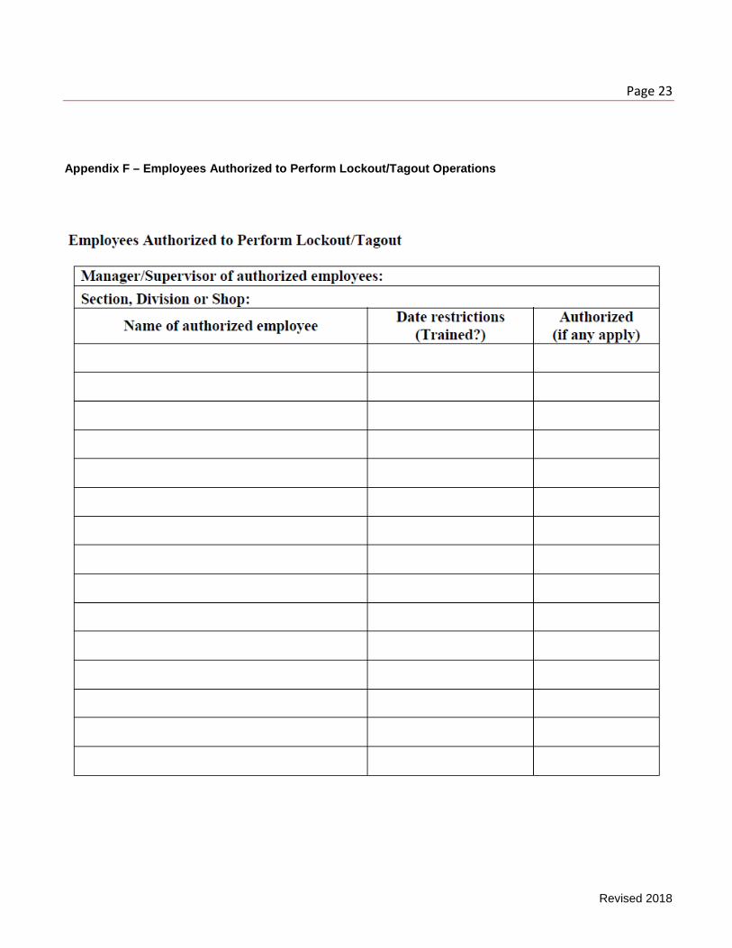
Appendix F – Employees Authorized to Perform Lockout/Tagout Operations
Page 24
Revised 2018
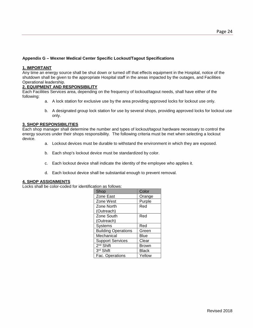
Appendix G – Wexner Medical Center Specific Lockout/Tagout Specifications 1. IMPORTANT Any time an energy source shall be shut down or turned off that effects equipment in the Hospital, notice of the shutdown shall be given to the appropriate Hospital staff in the areas impacted by the outages, and Facilities Operational leadership. 2. EQUIPMENT AND RESPONSIBILITY Each Facilities Services area, depending on the frequency of lockout/tagout needs, shall have either of the following:
a. A lock station for exclusive use by the area providing approved locks for lockout use only.
b. A designated group lock station for use by several shops, providing approved locks for lockout use only.
3. SHOP RESPONSIBILITIES Each shop manager shall determine the number and types of lockout/tagout hardware necessary to control the energy sources under their shops responsibility. The following criteria must be met when selecting a lockout device.
a. Lockout devices must be durable to withstand the environment in which they are exposed.
b. Each shop’s lockout device must be standardized by color.
c. Each lockout device shall indicate the identity of the employee who applies it.
d. Each lockout device shall be substantial enough to prevent removal.
4. SHOP ASSIGNMENTS Locks shall be color-coded for identification as follows:
Shop Color Zone East Orange Zone West Purple Zone North (Outreach)
Red
Zone South (Outreach)
Red
Systems Red Building Operations Green Mechanical Blue Support Services Clear 2nd Shift Brown 3rd Shift Black Fac. Operations Yellow
Page 25
Revised 2018
Appendix G.1 – Wexner Medical Center Specific Energy Control Procedures / Chillers A piece of equipment with two or more power sources needs a specific energy control procedure. This procedure identifies the energy sources and the proper steps to use to lock out the equipment. 1. Locking Out A Chiller & Chiller Components A chiller’s wiring configuration is used to identify the energy sources that need to be locked out. Note: All chillers are different and their wiring configurations will vary from jobsite to jobsite.
a. Steps for locking out a chiller control panel.
b. Lock out the main power source by placing a lock and identification tag on the main disconnect. This power source will usually be high voltage (460V, 480V, etc.). Locking out the main power source will de-energize the step-down 460V-110V transformers, which will de-energize the step-down 110V-24V transformers.
c. Test the knife switch to see that the exiting energy has been shut down. This can be done by using a voltmeter and testing the switch at the bottom terminals.
d. Open the control panel and identify where the line voltage terminals are. There should be a grid that will help identify the line voltage. Using a voltmeter, test the terminals to see that the energy has been shut down. Note: When the digital control panel is showing a read out, this indicates that the panel is still energized. Older chillers that do not use electronic boards will not have digital readouts and will usually have physical relays and contacts that will be powered by line voltage. These types of control panels normally have a “power on” light.
e. Once all incoming power has been identified and tested to verify that the energy sources have been de-energized, the chiller control panel can be serviced.
2. Potential problems when locking out a chiller control panel. a. If the main disconnect is locked out, the power to the step-down 460V-110V transformer may be coming
from an outside source. Locking out the main disconnect will not de-energize this transformer. Note: The main disconnect for the outside source will have to be identified and locked out with a padlock and identification tag.
b. The incoming power source to the high voltage will not be de-energized when the knife switch inside the cabinet is disconnected. When working inside the main power cabinet, the incoming high voltage source should be located and locked out. Using a voltmeter, test the incoming source using the incoming terminals on the knife switch.
c. When locking out electrical equipment, test the disconnect using a voltmeter. Never test across a fuse when testing for voltage because if the fuse is bad it will give a false reading. Always use the switch contacts when measuring for voltage.
Page 26
Revised 2018
d. The control panel will have an external control voltage coming into the panel from the FMS. Normally this
cannot be de-energized. The FMS line must be identified in the control panel so that special precautions may be taken when working around this line.
e. The line voltage that is used to energize the refrigerant oil-heating element may also be coming from an outside source; therefore, when working on the heating element, the outside source must be identified and de-energized.
Page 27
Revised 2018
Appendix G.2 – Wexner Medical Center Specific Energy Control Procedures / Water Pumps A piece of equipment with two or more power sources needs a specific energy control procedure. This procedure identifies the energy sources and the proper steps to use to lock out the equipment. 1. Steps for locking out a condenser water pump or chilled water pump.
A. Two major components will need to be locked out when working on a condenser/chilled water pump.
a. First, lock out the main power source for the chiller by placing a lock and identification tag on the main disconnect. This power source will usually be high voltage (460V, 480V, etc.). This will de-energize the control panel, which will stop it from giving the condenser/chilled water pump a start command. NOTE: Locking out a chiller control panel is only practical if the chiller does not need to be running. If the chiller needs to be running and the primary or backup chilled water pump, or condensate pump needs to be serviced, the control panel cannot be locked out. The main disconnect to the pump must be locked out.
b. Second, lock out the condenser/chilled water pump’s main power source by tracing the conduit back to its main disconnect and locking out the pump.
B. Open the panel and use a voltmeter to test the terminals to see that the energy has been shut down (test the terminals coming off the knife switch or the fusible disconnect.). When working on the main disconnect, the incoming voltage will have to be locked out. This can be done by tracing the incoming conduit back to its main disconnect and locking it out. Test the incoming voltage at the condenser/chilled water pump’s main power box by testing the incoming line located above the knife switch or fusible disconnect.
C. Examine the condenser/chilled water pump’s main power box to make sure that all external power sources have been identified and locked out. This can be done by identifying the power sources that are feeding into the pump, following the conduit back to the power source, and then locking out the disconnect.
D. Place the ON/OFF/MANUAL (HAND-OFF-ON) switch on the ON position and make sure the pump does not start. If the pump starts, trace back all power sources from the pump and lock out all incoming power source disconnects. Retest the start up.
E. Once the main power source for the condenser/chilled water pump is locked out, and all exiting power sources from the pump have been identified, the equipment can be services.
2. Potential problems when locking out a condense water pump or a chilled water pump.
A. The condenser /chilled water pump’s main power source may be located in a separate room from the pump; therefore, if the pump’s main disconnect is not locked out and the switch is placed in the OFF position, someone could place the switch to the AUTO position. When the chiller’s control panel gives the
Page 28
Revised 2018
pump a start command it will be energized while working on it. The control panel and pump will need to be locked out before servicing the pump.
B. Never check across a fuse when testing for voltage because if the fuse is bad it will give a false reading. Always use the switch contacts when measuring for voltage. Note: The condenser/chilled water pump’s wiring configuration may be different from one jobsite to the next.
Page 29
Revised 2018
Appendix G.3 – Wexner Medical Center Specific Energy Control Procedures / Cooling Tower Fans A piece of equipment with two or more power sources needs a specific energy control procedure. This procedure identifies the energy sources and the proper steps to use to lock out the equipment. 1. Steps for locking out a cooling tower fan(s).
A. Two major components will need to be locked out when working on a cooling tower fan.
a. First, lockout/tagout the main power source for the chiller by placing a lock and identification tag on the main disconnect. This power source will usually be high voltage (460V, 480V, etc.). This will de-energize the control panel, which will stop it from giving the cooling tower fan(s) a start command. Note: Locking out a chiller control panel is only practical if the chiller does not need to be running. If the chiller needs to be running and the cooling tower needs to be serviced, the control panel cannot be locked out. The main disconnect for the fan’s motor must be locked out.
b. Second, lock out the cooling tower fan’s main power source. This can be done by tracing the conduit back to the fan’s main disconnect and locking out the fan.
B. Open the panel and use a voltmeter to test the terminals to see that the energy has been shut down (test the voltage that is coming off the knife switch or the fusible disconnect). The incoming voltage to the main disconnect will need to be locked out prior to servicing the main disconnect. This can be done by tracing the incoming conduit back to its main disconnect and locking out the disconnect. Test the incoming voltage by testing the terminal located on the incoming side of the knife switch.
C. Examine the cooling tower fan’s main power box to make sure that all external power exiting the box and going to the cooling tower fan(s) has been identified and locked out. This can be done by identifying the power sources that are feeding into the fan and following the conduit back to the power source.
D. Place the ON/OFF/MANUAL (HAND-OFF-ON) switch to the ON position to make sure the fan does not start. If the fan starts, trace back all power sources from the fan and lock out all incoming power source disconnects. Retest to make sure that all incoming power sources have been identified and locked out.
E. Once the main power sources have been locked out for the chiller control panel and the cooling tower fan(s), and all exiting power sources from the main disconnect have been identified and locked out, the equipment can be serviced.
2. Potential problems when locking out a cooling tower fan(s).
A. The cooling tower fan’s main power source may be located in a separate room from the fan; therefore, if the fan’s disconnect is not locked out and the switch is placed in the OFF position, someone could place the switch to the AUTO position. When the chiller gives the fan(s) the start command it will be energized. The control panel, fan, and all incoming power sources must be locked out prior to servicing the fan(s).
Page 30
Revised 2018
B. When locking out electrical equipment, test the disconnect using a voltmeter. Never test across a fuse
when testing for voltage because if the fuse is bad it will give a false reading. Always use the switch contacts when measuring for voltage. Note: The wiring configurations of cooling tower fan(s) may be different from one jobsite to the next.
Page 31
Revised 2018
Appendix G.4 – Wexner Medical Center Specific Energy Control Procedures / Air Handlers A piece of equipment with two or more power sources needs a specific energy control procedure. This procedure identifies the energy sources and the proper steps to use to lock out the equipment. 1. Steps for locking out a multi-zone/VAV air handler.
A. Identify the main power source that energizes the air handler’s fan(s). Lock out the main power source by placing the control switch to the OFF position and placing a padlock and identification tag on the disconnect.
B. Open the box and use a voltmeter to test the switch terminals located at the bottom of the switch.
C. Examine the box and identify any other power sources that are coming into it. External voltage may be coming into the box that will need to be locked out at a different disconnect. When identifying another incoming power source, trace the conduit back to the disconnect and lock out the disconnect.
D. While working inside the disconnect box (replacing fuses, knife switches, etc.), the incoming power to the switch/fuse must be locked out. This can be done by following the conduit that is coming off the box to another disconnect. Lock out this disconnect by placing a padlock and identification tag on it. Use a voltmeter to test the voltage that is coming into the switch/fuse by testing the terminals on top of the switch/fuse.
E. Identify the control panel that is controlling the air handler and locate its main power source. Identify the line voltage that is coming into the panel by tracing the conduit to the sources disconnects. Place the disconnect to the OFF position and place a padlock and identification tag on the disconnect.
F. Place the ON/OFF/MANUAL (HAND-OFF-ON) switch to the ON position and make sure the pump does not start. If the pump starts, trace back all power sources from the pump and lock out all incoming power source disconnects. Retest the start up.
G. When all power sources to the air handler and control panel have been identified and locked out, the air handler can be serviced.
2. Potential problems when locking out a multi-zone/VAV air handler. A. Air handlers will have different wiring configurations. It may be very difficult to identify where the
disconnect is for a fan(s), and, therefore, the customer representative should be contacted for assistance.
B. When the air handler’s control panel and main power to the fan motor(s) is not locked out, the panel may send a signal to a relay, which will send line voltage to the air handler.
Page 32
Revised 2018
Appendix G.5 – Wexner Medical Center Specific Energy Control Procedures / Boiler A piece of equipment with two or more power sources needs a specific energy control procedure. This procedure identifies the energy sources and the proper steps to use to lock out the equipment. 1. Locking Out A Boiler When a boiler needs to be opened, the water must be completely drained and the boiler allowed to cool to an appropriate temperature before anyone enters.
A. Main power source.
a. Lock out the main power source coming into the main power box. This will lock out the control panel, main fan, and any fuel oil pre-heaters (if the boiler is using fuel oil).
b. Test the knife switch to see that the exiting energy has been de-energized. This can be done
using a voltmeter to test the switch terminals at the bottom terminals.
c. When working inside the main power cabinet, the incoming high voltage source should be located and locked out. Using a voltmeter, test the incoming source by testing the incoming terminals on the knife switch.
d. Using a voltmeter, test the control panel to make sure that all incoming line voltage has been de-
energized.
e. Examine the main power box and control panel to identify any other incoming line voltage. This can be done by following the conduit back to its main disconnect and locking out the disconnect.
2. Fuels. A. Natural gas.
a. There will normally be two valves that will control the gas flow to the boiler. The first will control
the gas flow for the specific boiler. This valve will be located on the boiler. The second will be the main valve that will control the gas for the boiler and any other equipment fueled by gas. This valve can be located by following the boiler’s gas line.
b. Lock out the boiler’s gas valve by placing a ball valve lock out or a chain and padlock on the
handle.
c. Whenever possible, lock out the main gas valve. This may not be possible when working on a boiler that is in a series of boilers, or when the valve is supplying gas to other equipment.
Page 33
Revised 2018
Note: When shutting off the gas valve to a boiler and not locking out the main gas valve, the pilot light to the boiler may still be on. Follow the pilot light back to a ball valve and lock out the valve.
B. Fuel oil.
a. Lock out the fuel oil line to the boiler by locking out the ball valve that controls the flow from the fuel oil tank to the boiler.
3. Feed water pump. A. Using a lock and identification tag, lock out the feed water pump’s main disconnect. Using a voltmeter,
test the knife switch by testing the lower terminals.
B. Examine the main disconnect and pump for any other incoming line voltage. Note: Large jobsites may have several boilers that are connected; therefore, the feed water pump will not be able to be locked out because it will have to service other boilers. When this occurs, lock out the valve (use a valve cover lock out device) that feeds the boiler being serviced.
4. Condensate pump. A. When servicing a stand-alone boiler, the condensate pump will not have to be locked out because there
will be no condensation from the boiler going to the condensate tank.
B. When servicing a boiler that is part of a multiple boiler connection, the pipe that is going from the boiler to the condensate pump will have to be shut off and locked out. This will allow the condensate pump to service the other boiler(s).
5. Distribution valve. A. Lock out the main distribution valve by shutting the valve off and placing a chain and lock on it to secure
the valve. This valve will be located on top of the boiler.
B. The distribution valve must always be locked out when working inside a boiler. Locking out this valve will prevent any steam from coming back down into the boiler.