Embed Size (px)
Citation preview
A SERVICE PUBLICATION OFLOCKHEED-GEORGIA COMPANYA DIVISION OFLOCKHEED AIRCRAFT CORPORATION
EditorJay V. Roy
Associate EditorsDon H. HungateJames A. Loftin
Art Direction & ProductionAnne G. Anderson
VOL. 4, NO. 2, April - June 1977
CONTENTS
3 Leaky Fasteners5 Description of Fastener Systems6 Chart - History of Fasteners Used in
Hercules Integral Wing Tanks12 Leak Detection and Repair
15 Repair of Rubber Coveringon lnflight Refueling Hoses
15 New Check ValveSpecified for Hercules HydraulicPump Pressure Lines
1 4 StarTipsInstallation Tool - Wing LeadingEdge Hinge Pin
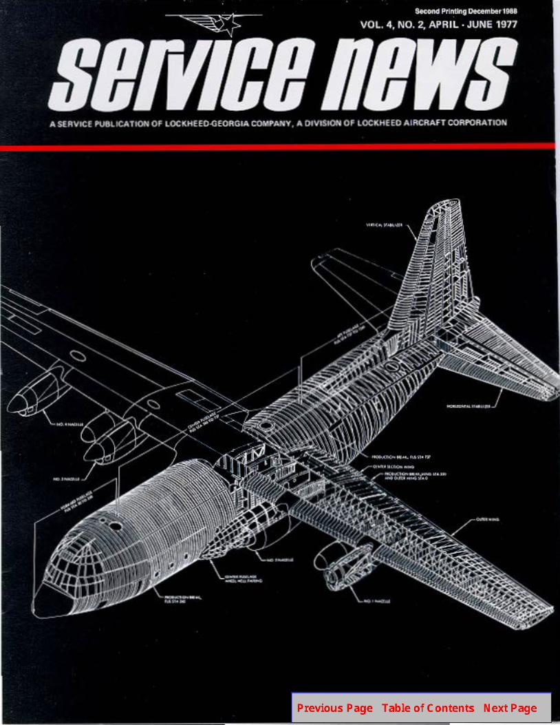
Front Cover: Inside the Hercules -this months cover depicts a simplifiedcutaway of the Hercules, representativeof the C-l 30H configuration.
Published by Lockheed-Georgia Company, a Division ofLockheed Aircraft Corporation. Information contained inthis issue is considered by Lockheed-Georgia Company tobe accurate and authoritative; it should not be assumed,however, that this material has received approval from anygovernmental agency or military service unless it isspecifically noted. This publication is for planning andinformation purposes only, and it is not to be construedas authority for making changes on aircraft or equipment,or as superseding any established operational ormaintenance procedures or policies. The following marksare registered and owned by Lockheed AircraftCorporation: “ “, “Lockheed”, “Hercules”, and“JetStar”. Written permission must be obtained fromLockheed-Georgia Company before republishing anymaterial in this periodical. Address all communications toEditor, Service News, Department 64-22, Zone 278,Lockheed-Georgia Company, Marietta, Georgia 30063.Copyright 1977 Lockheed Aircraft Corporation.
SERVICE is our Business
Customer Service
Division
D. L. BRAUND, MGR
H. L. BURNETTE, MGRJetStar Support Dept
E. L. PARKER, MGRCustomer Training Dept
A. H. McCRUM, MGRField Service 81 I nventc
Management Oept
J. K. PIERCE, MGRSpares Stores &Ship ping Dept
ory
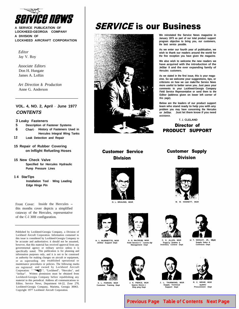
We reinstated the Service News magazine inJanuary 1973 as part of our total product supportprogram objective to bring you, our customers,the best service possible.
As we enter our fourth year of publication, wewish to thank our readers around the world forthe fine reception you have given the magazine.
We also wish to welcome the new readers wehave acquired with the introduction of theJetStar II and the ever expanding family ofHercules customers.
As we stated in the first issue, this is your maga-zine. So we welcome your suggestions, tips, orcriticisms on how we can make’the Service Newsmore useful to better serve you. Just pass yourcomments to your Lockheed-Georgia CompanyField Service Representative or send them to theEditor (address given on lower left corner ofthis page).
Below are the leaders of our product supportteam who stand ready to help you with anyproblem you may have concerning the Herculesor JetStar. Just let them know if you needassistance.
T. J. CLELAND
Director ofPRODUCT SUPPORT
Customer SupplyDivision
M. M. HODNETT, MGR
C. K. ALLEN, MGRSupply Systems &
Inventory Control Dept
J. L. THURMOND, MGRSupply Technical
Support Dept
. T. NISSLEY, JR., MGSupply Sales &Contracts Oept
R. C. WEIHE, MGRSUPPlY
Procurement Dept

by M. G. Billias, Development Engineer SpecialistM. V. Cobb, Jr., Design Engineer, SeniorF. D. Poss, Components Engineer, Senior
The development and use of the aircraft integral fuel tankhas resulted in problems along with the many advantagesof the system.One of the more chronic problems is thatof fuel tank leaks; and, as with any other aircraft, theHercules is susceptible to such leaks. A major cause offuel tank leaks is the fasteners.
This article provides general information on how to detectand eliminate existing fastener leaks, and how to minimizefuture fastener leaks. Items covered are: The variousHercules tank configurations, purpose of fasteners, adescription of five different fastener systems, installationand removal techniques, use of oversized fasteners, leakdetection and repair, and testing.
A BRIEF HISTORY
The Hercules has gone through several model changes overthe years; and, although the outward appearance of theairplane is the same, many aspects of the airplane havebeen greatly improved. This includes the sealing of theintegral fuel tanks and the introduction of improvedfastener systems.
The original “A” series aircraft integral fuel tanks werenot sealed in the faying surfaces; sealing was limited to
post-assembly sealed fillets and brush coats. This sealingprocedure caused extreme difficulties in locating a trueleak source since leaks could “channel” along a seam Theoriginal sealant used was a polysulfide type conforming toMIL-S-7502. This was topcoated with MILS-4383 BunaN. These were the best materials available at that time.
Faying-surface sealing was not used on earlier modelaircraft due to a belief that applying an elastic sealant inthe faying surfaces was structurally unacceptable andwould result in excessive flexing of the wing. It has sincebeen proven that faying-surface sealing, properly accom-plished, does not degrade the structure and offers a bigadvantage to fuel tank sealing as well as to corrosioncontrol.
Lockheed has always used the latest state-of-the-artmaterials for sealing and coating the fuel tanks; and, as a
3
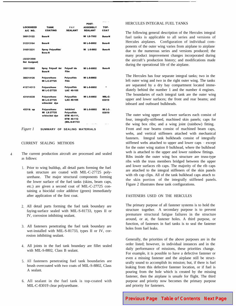
result, various sealing and coating materials can be foundin the fuel tanks.A summary of the materials used in themanufacture of the Hercules is listed in Figure 1. Itshould be realized that the original materials used insealing and coating the tanks may no longer be in service.Certain older aircraft that have undergone numerousmodifications or update programs will probably containthe latest coatings and sealants.
LOCKHEED
A/C NO.
3001/3122
312313164
316513231
(323213500
Not Assigned)
350113882
388314126
4127/4313
431414330
4331& up
TANKCOATING
Buna-N
Buna-N
Spray Polysulfide/
Bona-N
Spray Polysulf ide/
Buna-N
Polyurethane
Ml L-C-27725
Polyurethane
Ml L-C-27725
Polyurethane
Ml L-C-27725w/biocidal dye
PolyurethaneMl LX-27725
w/biocidal dye
F A YSEALANT
Polysulf ide
Film
Polysulfide
Film
Polysulfide
LAC 40-105
Polysulfide
LAC 40-105
Inhibited
Polysulfide
STM 40-111,
STM 40-112(MIL-S-81733
POST-
ASSEMBLYSEALANT
Ml LS-7502
Ml L-S-8802
Ml L-S-8802
Ml L-S-8802
Ml L-S-8802
Ml L-S-8802
Ml L-S-8802
Ml L-S-8802
TOP-
COAT
Buna-N
Buna-N
Buna-N
Buna-N
-
MIL-C-
83019
MI L-C-
83019
Figure 1 SUMMARY OF SEALING MATERIALS
CURRENT SEALING METHODS
4 The current production aircraft are processed and sealedas
1.
2.
3.
4.
5.
6.
follows:
Prior to wing buildup, all detail parts forming the fueltank structure are coated with MIL-C-27725 poly-urethane. The major structural components formingthe lower surface of the fuel tanks (skins, beam caps,etc.) are given a second coat of MIL-C-27725 con-taining a biocidal color additive (green) immediatelyafter application of the first coat.
All detail parts forming the fuel tank boundary arefaying-surface sealed with MIL-S-81733, types II orIV, corrosion inhibiting sealant.
All fasteners penetrating the fuel tank boundary arewet-installed with MIL-S-81733, types II or IV, cor-rosion inhibiting sealant.
All joints in the fuel tank boundary are fillet sealedwith MIL-S-8802, Class B sealant.
All fasteners penetrating fuel tank boundaries arebrush overcoated with two coats of MIL-S-8802, ClassA sealant.
All sealant in the fuel tank is top-coated withMIL-C-83019 clear polyurethane.
HERCULES INTEGRAL FUEL TANKS
The following general description of the Hercules integralfuel tanks is applicable to all series and versions ofHercules airplanes. Configuration of individual com-ponents of the outer wing varies from airplane to airplanedue to the numerous series and versions produced; themany product improvement changes incorporated duringthe aircraft’s production history; and modifications madeduring the operational life of the airplane.
The Hercules has four separate integral tanks; two in theleft outer wing and two in the right outer wing. The tanksare separated by a dry bay compartment located imme-diately behind the number 1 and the number 4 engines.The boundaries of each integral tank are the outer wingupper and lower surfaces; the front and rear beams; andinboard and outboard bulkheads.
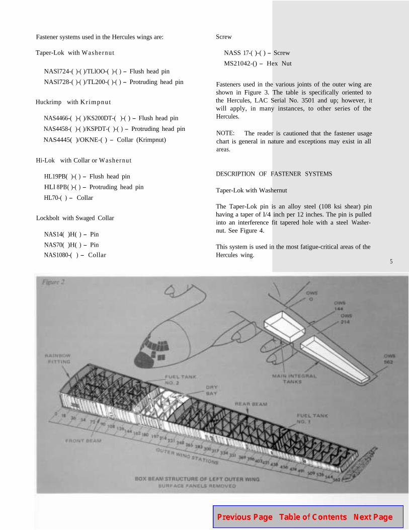
The outer wing upper and lower surfaces each consist offour, integrally-stiffened, machined skin panels; caps forthe wing box ribs; and a wing joint (rainbow) fitting.Front and rear beams consist of machined beam caps,webs, and vertical stiffeners attached with mechanicalfasteners. Integral tank bulkheads consist of integrallystiffened webs attached to upper and lower caps - exceptfor the outer wing station 0 bulkhead, where the bulkheadweb is attached to the upper and lower rainbow fittings.Ribs inside the outer wing box structure are truss-typeribs with the truss members bridged between the upperand lower surfaces rib caps. The majority of the rib capsare attached to the integral stiffeners of the skin panelswith rib cap clips. All of the tank bulkhead caps attach tothe skin portion of the integrally stiffened panels.Figure 2 illustrates these tank configurations.
FASTENERS USED ON THE HERCULES
The primary purpose of all fastener systems is to hold thestructure together.A secondary purpose is to preventpremature structural fatigue failures in the structurearound, or at, the fastener holes. A third purpose, orfunction, of fasteners in fuel tanks is to seal the fastenerholes from fuel leaks.
Generally, the priorities of the above purposes are in theorder listed; however, in individual instances and in thedaily performance of missions, these priorities change.For example, it is possible to have a defective fastener oreven a missing fastener and the airplane still be struct-urally sound to accomplish its mission; but, if there is fuelleaking from this defective fastener location, or if fuel ispouring from the hole which is created by the missingfastener, then the airplane is unsafe for flight. The thirdpurpose and priority now becomes the primary purposeand priority for fasteners.
Fastener systems used in the Hercules wings are:
Taper-Lok with Washernut
Screw
NASS 17-( )-( ) - Screw
MS21042-() - Hex NutNASl724-( )-( )/TLlOO-( )-( ) - Flush head pin
NASl728-( )-( )/TL200-( )-( ) - Protruding head pin
Huckrimp with Kr impnut
NAS4466-( )-( )/KS200DT-( )-( ) - Flush head pin
NAS4458-( )-( )/KSPDT-( )-( ) - Protruding head pin
NAS4445( )/OKNE-( ) - Collar (Krimpnut)
Fasteners used in the various joints of the outer wing areshown in Figure 3. The table is specifically oriented tothe Hercules, LAC Serial No. 3501 and up; however, itwill apply, in many instances, to other series of theHercules.
NOTE: The reader is cautioned that the fastener usagechart is general in nature and exceptions may exist in all
Hi-Lok with Collar or Washernut
HL19PB( )-( ) - Flush head pin
HLl 8PB( )-( ) - Protruding head pin
HL70-( ) - Collar
Lockbolt with Swaged Collar
NAS14( )H( ) - Pin
NAS70( )H( ) - Pin
NAS1080-( ) - Collar
areas.
DESCRIPTION OF FASTENER SYSTEMS
Taper-Lok with Washernut
The Taper-Lok pin is an alloy steel (108 ksi shear) pinhaving a taper of l/4 inch per 12 inches. The pin is pulledinto an interference fit tapered hole with a steel Washer-nut. See Figure 4.
This system is used in the most fatigue-critical areas of theHercules wing.
5
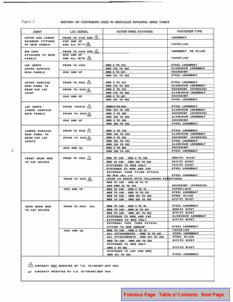
Figure 3 HISTORY OF FASTENERS USED IN HERCULES INTEGRAL WING TANKS
6
JOINT LAC SERIAL OUTER WING STATIONS FASTENER TYPE
UPPER AND LOWER PRIOR TO 4195 AND LOCKBOLT
RAINBOW FITTINGS 4195 AND UP
TO SKIN PANELS AND ALL TAPER -LOK
RIB CAPS PRIOR TO 4542 AND LOCKBOLT OR HI-LOK
ATTACHED TO SKIN 4542 AND UP
PANELS AND ALL WITH TAPER -LOK
LAP JOINTS -
UPPER SURFACE
SKIN PANELS
PRIOR TO 4542
4542 AND UP
OWS 6 TO 216
OWS 216 TO 562
OWS 6 TO 421
OWS 421 TO 562
STEEL LOCKBOLT
A L U M I N UM LOCKBOLT
H U C K R I M P
STEEL LOCKBOLT
UPPER SURFACE
SKIN PANEL TO
BEAM CAP LAP
JOINT
PRIOR TO 4542
PRIOR TO 4542
4542 AND UP
OWS 6 TO 216
OWS 216 TO 562
OWS 6 TO 310
OWS 310 TO 562
OWS 6 TO 421
OWS 421 TO 562
STEEL LOCKBOLT
A L U M I N UM LOCKBOLT
HUCKRIMP (OVERSIZE)
A L U M I N U M LOCKBOLT
H U C K R I M P
STEEL LOCKBOLT
LAP JOINTS -
LOWER SURFACE
SKIN PANELS
PRIOR TO4542
PRIOR TO 4542
4542 AND UP
OWS 6 TO 216
OWS 216 TO 562
OWS 6 TO 300
OWS 300 TO 562
OWS 6 TO 386
OWS 386 TO 562
STEEL LOCKBOLT
A L U M I N UM LOCKBOLT
HUCKRIMP (OVERSIZE)
A L U M I N UM LOCKBOLT
H U C K R I M P
STEEL LOCKBOLT
LOWER SURFACE
SKIN PANEL TO
BEAM CAP LAP
JOINTS
PRIOR TO 4542
PRIOR TO 4542
4542 AND Up
OWS 6 TO 334
OWS 334 TO 562
OWS 6 TO 302
OWS 302 TO 334
OWS 334 TO 562
OWS 6 TO 386
OWS 386 TO 562
STEEL LOCKBOLT
A L U M I N UM LOCKBOLT
HUCKRIMP (OVERSIZE)
STEEL LOCKBOLT
A L U M I N UM LOCKBOLT
H U C K R I M P
STEEL LOCKBOLT
FRONT BEAM WEB
TO CAP SPLICES
PRIOR TO 4542
PRIOR TO 4542
4542 AND UP
WEB TO CAP - OWS 6 TO 300 2024-T31 R IVET
WEB TO CAP - OWS 300 TO 562 2117-T3 RIVET
STIFFENER TO WEB ONLY 7117-T3 RIVET
STIFFENER TO WEB AND CAP STEEL LOCKBOLT
EXTERNAL TANK PYLON ATTACH.
TO W EB AN D C A P STEEL LOCKBOLT
(SAME AS ABOVE WITH FOLLOWING EXCEPTIONS)
WEB TO CAP - OWS 58 TO 70
AND OWS 92 TO 104 HUCKRIMP (OVERSIZE)
WEB TO CAP - OWS 6 TO 18 TAPER -LOCK
WEB TO CAP - OWS 18 TO 351 STEEL LOCKBOLT
WEB TO CAP - OWS 351 TO 426 STEEL HI-LOK
WEB TO CAP - OWS 426 TO 562 2117-T3 RIVET
REAR BEAM WEB
TO CAP SPLICES
PRIOR TO 4542 - ALL
4542 AND Up
WEB TO CAP - OWS 6 TO 36 STEEL LOCKBOLT
WEB TO CAP - OWS 36 TO 401 2024-T3 RIVET
WEB TO CAP - OWS 401 TO 562 2117-T3 RIVET
STIFFENER TO WEB AND CAP A L U M I N UM LOCKBOLT
STIFFENER TO WEB ONLY 2117-T3 RIVET
EXTERNAL FUEL TANK ATTACH.
FITTING TO WEB ANDCAP STEEL LOCKBOLT
WEB TO CAP - OWS 6 TO 18 TAPER -LOK
ALL ATTACHMENTS - OWS 18 TO 401 STEEL LOCKBOLT
ALL ATTACHMENTS - OWS 401 TO 456 STEEL HI-LOK
WEB TO CAP - OWS 456 TO 562 2117-T3 RIVET
STIFFENER TO WEB ONLY -OWS 6 TO 562 2117-T3 R IVET
STIFFENER TO CAP AND WEB
OWS 401 TO 562 STEEL LOCKBOLT
AIRCRAFT NOT MODIFIED BY T.O. 1C-130-857 (ECP 954)
A2 AIRCRAFT MODIFIED BY T.O. 1C-130-857 (ECP 954)
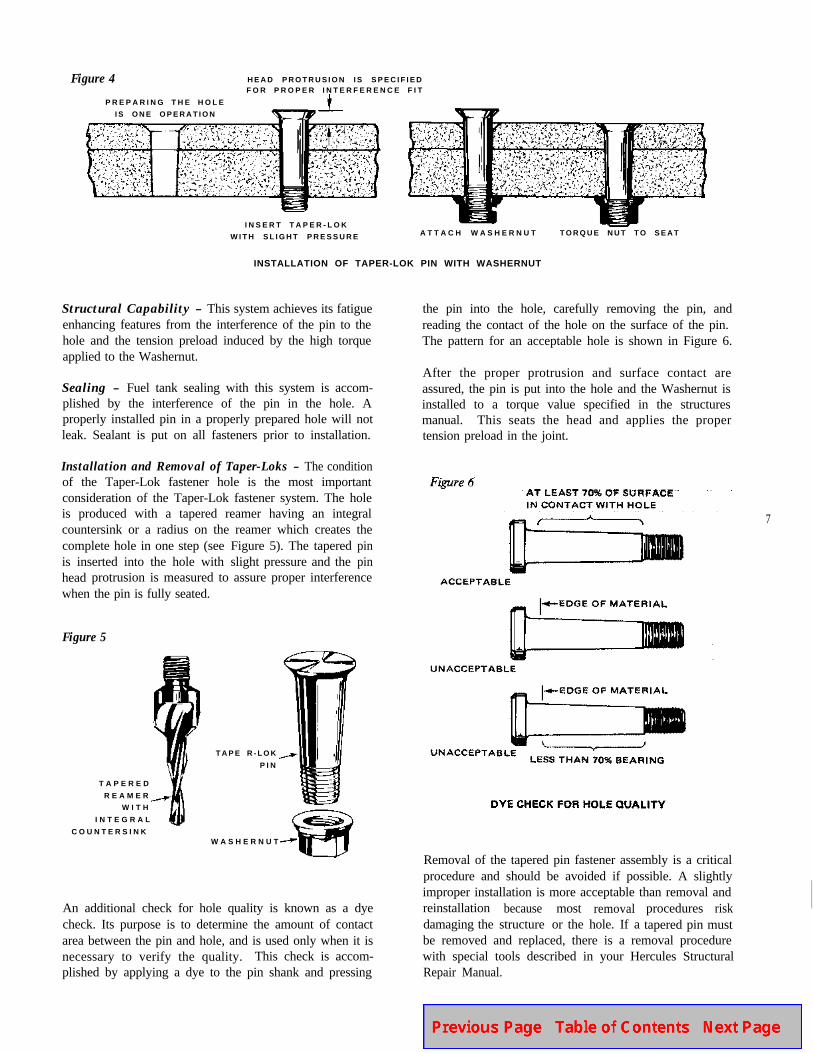
Figure 4 H E A D P R O T R U S I O N I S S P E C I F I E DF O R P R O P E R I N T E R F E R E N C E F I T
P R E P A R I N G T H E H O L E
I S O N E O P E R A T I O N
I N S E R T T A P E R - L O K
W I T H S L I G H T P R E S S U R E A T T A C H W A S H E R N U T T O R Q U E N U T T O S E A T
INSTALLATION OF TAPER-LOK PIN WITH WASHERNUT
Structural Capability - This system achieves its fatigueenhancing features from the interference of the pin to thehole and the tension preload induced by the high torqueapplied to the Washernut.
Sealing - Fuel tank sealing with this system is accom-plished by the interference of the pin in the hole. Aproperly installed pin in a properly prepared hole will notleak. Sealant is put on all fasteners prior to installation.
Installation and Removal of Taper-Loks - The conditionof the Taper-Lok fastener hole is the most importantconsideration of the Taper-Lok fastener system. The holeis produced with a tapered reamer having an integralcountersink or a radius on the reamer which creates thecomplete hole in one step (see Figure 5). The taperedpinis inserted into the hole with slight pressure and thepinheadprotrusion is measured to assure proper interferencewhen the pin is fully seated.
Figure 5
T A P E R E D
R E A M E R
W I T H
I N T E G R A L
C O U N T E R S I N K
T A P E R - L O K
P I N
W A S H E R N U T
An additional check for hole quality is known as a dyecheck. Its purpose is to determine the amount of contactarea between the pin and hole, and is used only when it isnecessary to verify the quality.This check is accom-plished by applying a dye to the pin shank and pressing
the pin into the hole, carefully removing the pin, andreading the contact of the hole on the surface of the pin.The pattern for an acceptable hole is shown in Figure 6.
After the proper protrusion and surface contact areassured, the pin is put into the hole and the Washernut isinstalled to a torque value specified in the structuresmanual. This seats the head and applies the propertension preload in the joint.
Removal of the tapered pin fastener assembly is a criticalprocedure and should be avoided if possible. A slightlyimproper installation is more acceptable than removal andreinstallationdamaging the
becausestructure
mostor the
removal procedures riskhole. If atapered pin must
be removed and replaced, there is a removal procedurewith special tools described in your Hercules StructuralRepair Manual.
7
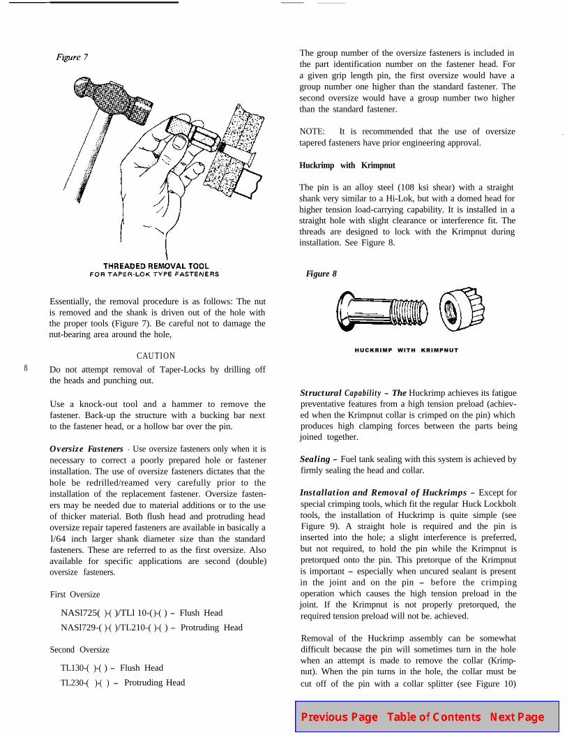
Essentially, the removal procedure is as follows: The nutis removed and the shank is driven out of the hole withthe proper tools (Figure 7). Be careful not to damage thenut-bearing area around the hole,
8CAUTION
Do not attempt removal of Taper-Locks by drilling offthe heads and punching out.
Use a knock-out tool and a hammer to remove thefastener. Back-up the structure with a bucking bar nextto the fastener head, or a hollow bar over the pin.
Oversize Fasteners - Use oversize fasteners only when it isnecessary to correct a poorly prepared hole or fastenerinstallation. The use of oversize fasteners dictates that thehole be redrilled/reamed very carefully prior to theinstallation of the replacement fastener. Oversize fasten-ers may be needed due to material additions or to the useof thicker material. Both flush head and protruding headoversize repair tapered fasteners are available in basically al/64 inch larger shank diameter size than the standardfasteners. These are referred to as the first oversize. Alsoavailable for specific applications are second (double)oversize fasteners.
First Oversize
NASl725( )-( )/TLl 10-( )-( ) - Flush Head
NASl729-( )-( )/TL210-( )-( ) - Protruding Head
Second Oversize
TL130-( )-( ) - Flush Head
TL230-( )-( ) - Protruding Head
The group number of the oversize fasteners is included inthe part identification number on the fastener head. Fora given grip length pin, the first oversize would have agroup number one higher than the standard fastener. Thesecond oversize would have a group number two higherthan the standard fastener.
NOTE: It is recommended that the use of oversizetapered fasteners have prior engineering approval.
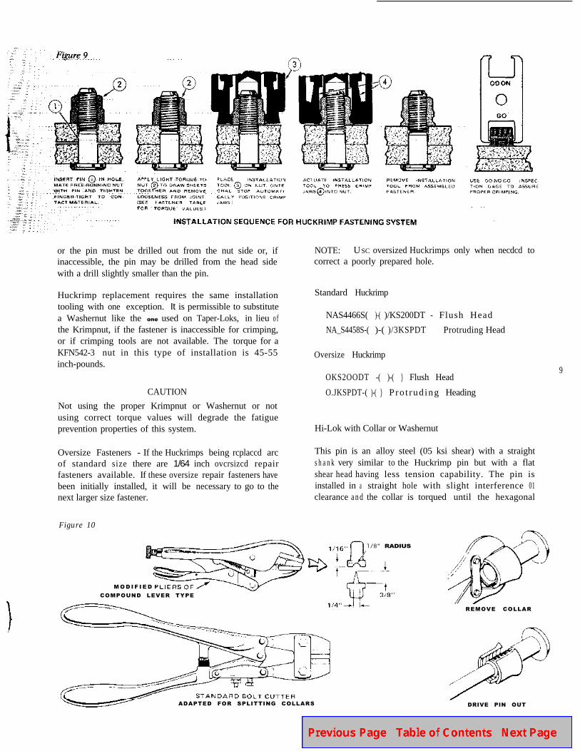
Huckrimp with Krimpnut
The pin is an alloy steel (108 ksi shear) with a straightshank very similar to a Hi-Lok, but with a domed head forhigher tension load-carrying capability. It is installed in astraight hole with slight clearance or interference fit. Thethreads are designed to lock with the Krimpnut duringinstallation. See Figure 8.
Figure 8
HUCKRIMP WITH KRIMPNUT
Structural Capability - The Huckrimp achieves its fatiguepreventative features from a high tension preload (achiev-ed when the Krimpnut collar is crimped on the pin) whichproduces high clamping forces between the parts beingjoined together.
Sealing - Fuel tank sealing with this system is achieved byfirmly sealing the head and collar.
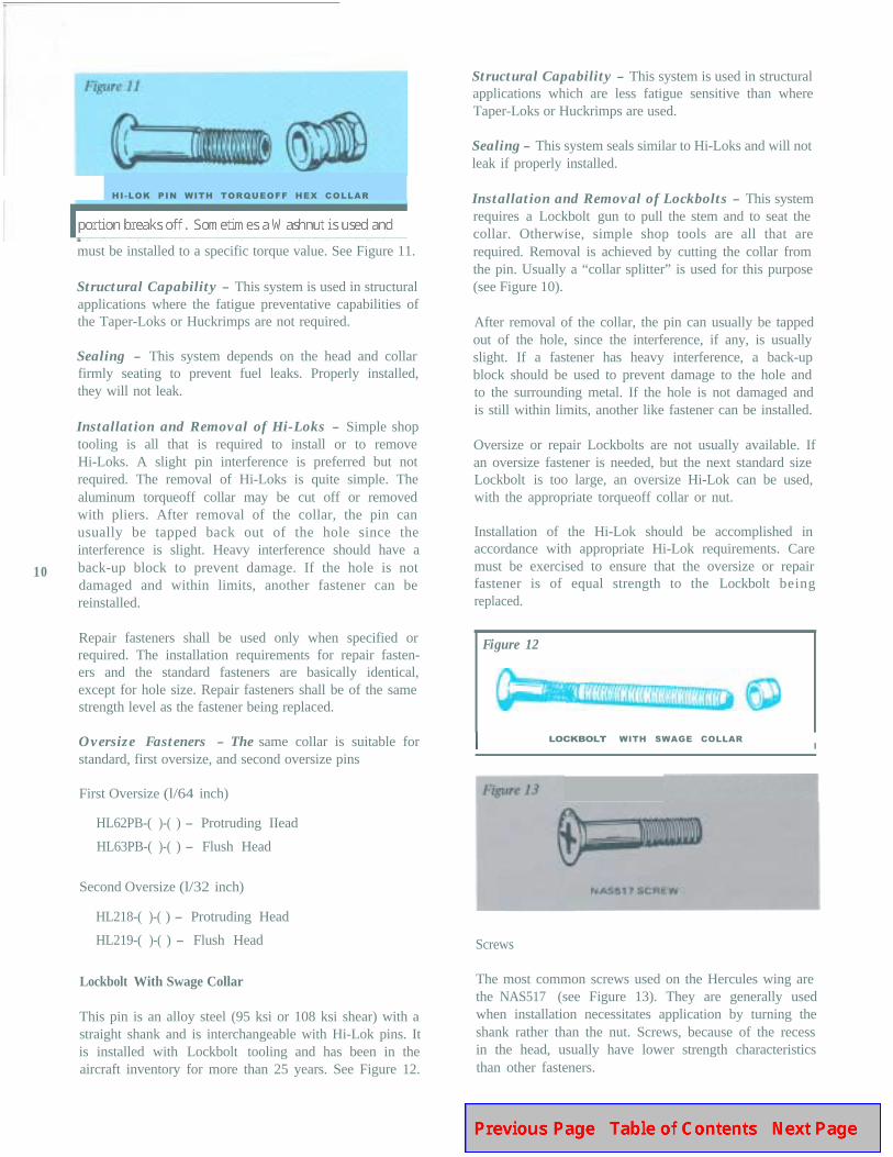
Installation and Removal of Huckrimps - Except forspecial crimping tools, which fit the regular Huck Lockbolttools, the installation of Huckrimp is quite simple (seeFigure 9). A straight hole is required and the pin isinserted into the hole; a slight interference is preferred,but not required, to hold the pin while the Krimpnut ispretorqued onto the pin. This pretorque of the Krimpnutis important - especially when uncured sealant is presentin the joint and on the pin - before the crimpingoperation which causes the high tension preload in thejoint. If the Krimpnut is not properly pretorqued, therequired tension preload will not be. achieved.
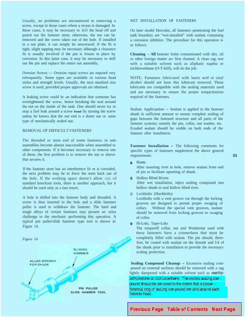
Removal of the Huckrimp assembly can be somewhatdifficult because the pin will sometimes turn in the holewhen an attempt is made to remove the collar (Krimp-nut). When the pin turns in the hole, the collar must becut off of the pin with a collar splitter (see Figure 10)
or the pin must be drilled out from the nut side or, ifinaccessible, the pin may be drilled from the head sidewith a drill slightly smaller than the pin.
NOTE: USC oversized Huckrimps only when necdcd tocorrect a poorly prepared hole.
Huckrimp replacement requires the same installationtooling with one exception. It is permissible to substitutea Washernut like the one used on Taper-Loks, in lieu o fthe Krimpnut, if the fastener is inaccessible for crimping,or if crimping tools are not available. The torque for aKFN542-3 nut in this type of installation is 45-55inch-pounds.
Standard Huckrimp
NAS4466S( )-( )/KS200DT - Flush Head
NA_S4458S-( )-( )/3KSPDT Protruding Head
Oversize Huckrimp
OKS2OODT -( )-( ) Flush Head
CAUTION O.JKSPDT-( )-( ) Pro t rud ing Heading
Not using the proper Krimpnut or Washernut or notusing correct torque values will degrade the fatigueprevention properties of this system. Hi-Lok with Collar or Washernut
Oversize Fasteners - If the Huckrimps being rcplaccd arcof standard size there are 1/64 inch ovcrsizcd repairfasteners available. If these oversize repair fasteners havebeen initially installed, it will be necessary to go to thenext larger size fastener.
This pin is an alloy steel (05 ksi shear) with a straights h a n k very similar to the Huckrimp pin but with a flatshear head having less tension capability. The pin isinstalled in a straight hole with slight interference 01clearance and the collar is torqued until the hexagonal
Figure 10
l/8" RADIUS
M O D I F I E D
COMPOUND LEVER TYPE
ADAPTED FOR SPLITTING COLLARS
REMOVE COLLAR
DRIVE PIN OUT
9
HI-LOK PIN WITH TORQUEOFF HEX COLLAR
must be installed to a specific torque value. See Figure 11.
Structural Capability - This system is used in structuralapplications where the fatigue preventative capabilities ofthe Taper-Loks or Huckrimps are not required.
Sealing - This system depends on the head and collarfirmly seating to prevent fuel leaks. Properly installed,they will not leak.
10
Installation and Removal of Hi-Loks - Simple shoptooling is all that is required to install or to removeHi-Loks. A slight pin interference is preferred but notrequired. The removal of Hi-Loks is quite simple. Thealuminum torqueoff collar may be cut off or removedwith pliers. After removal of the collar, the pin canusually be tapped back out of the hole since theinterference is slight. Heavy interference should have aback-up block to prevent damage. If the hole is notdamaged and within limits, another fastener can bereinstalled.
Repair fasteners shall be used only when specified orrequired. The installation requirements for repair fasten-ers and the standard fasteners are basically identical,except for hole size. Repair fasteners shall be of the samestrength level as the fastener being replaced.
Oversize Fasteners - The same collar is suitable forstandard, first oversize, and second oversize pins
First Oversize (l/64 inch)
HL62PB-( )-( ) - Protruding IIead
HL63PB-( )-( ) - Flush Head
Second Oversize (l/32 inch)
HL218-( )-( ) - Protruding Head
HL219-( )-( ) - Flush Head
Lockbolt With Swage Collar
This pin is an alloy steel (95 ksi or 108 ksi shear) with astraight shank and is interchangeable with Hi-Lok pins. Itis installed with Lockbolt tooling and has been in theaircraft inventory for more than 25 years. See Figure 12.
Structural Capability - This system is used in structuralapplications which are less fatigue sensitive than whereTaper-Loks or Huckrimps are used.
Sealing - This system seals similar to Hi-Loks and will notleak if properly installed.
Installation and Removal of Lockbolts - This systemrequires a Lockbolt gun to pull the stem and to seat thecollar. Otherwise, simple shop tools are all that arerequired. Removal is achieved by cutting the collar fromthe pin. Usually a “collar splitter” is used for this purpose(see Figure 10).
After removal of the collar, the pin can usually be tappedout of the hole, since the interference, if any, is usuallyslight. If a fastener has heavy interference, a back-upblock should be used to prevent damage to the hole andto the surrounding metal. If the hole is not damaged andis still within limits, another like fastener can be installed.
Oversize or repair Lockbolts are not usually available. Ifan oversize fastener is needed, but the next standard sizeLockbolt is too large, an oversize Hi-Lok can be used,with the appropriate torqueoff collar or nut.
Installation of the Hi-Lok should be accomplished inaccordance with appropriate Hi-Lok requirements. Caremust be exercised to ensure that the oversize or repairfastener is of equal strength to the Lockbolt beingreplaced.
Figure 12
LOCKBOLT WITH SWAGE COLLARI
Screws
The most common screws used on the Hercules wing arethe NAS517 (see Figure 13). They are generally usedwhen installation necessitates application by turning theshank rather than the nut. Screws, because of the recessin the head, usually have lower strength characteristicsthan other fasteners.
Usually, no problems are encountered in removing ascrew, except in those cases where a recess is damaged. Inthose cases, it may be necessary to drill the head off andpunch out the fastener stem; otherwise, the nut can beremoved and the screw taken out of the hole. If installedin a nut plate; it can simply be unscrewed. If the fit istight, slight tapping may be necessary although a clearancefit is usually involved if the pin is frozen in place bycorrosion. In this latter case, it may be necessary to drillout the pin and replace the entire nut assembly.
Oversize Screws --- Oversize repair screws are required veryinfrequently. Some types are available in various headstyles and strength levels. Usually, the next standard sizescrew is used, provided proper approvals are obtained.
A leaking screw could be an indication that someone hasovertightened the screw, hence breaking the seal aroundthe nut on the inside of the tank. One should never try tostop a fuel leak around a screw head by turning the screwunless he knows that the nut end is a dome nut or sometype of mechanically sealed nut.
REMOVAL OF DIFFICULT FASTENERS
The threaded or stem end of some fasteners in sub-assemblies become almost inaccessible when assembled toother components. If it becomes necessary to remove oneof these, the first problem is to remove the nut or sleevethat secures it.
If the fastener stem has an interference fit or is corroded,the next problem may be to force the stem back out ofthe hole. If the working space doesn’t allow USC o fstandard knockout tools, there is another approach, but itshould be used only as a last resort.
A hole is drilled into the fastener body and threaded. Ascrew is then inserted in the hole and a slide hammerpuller is used to withdraw the fastener. The hard andtough alloys of certain fasteners may present an extrachallenge to the mechanic performing this operation. Atypical pin puller/slide hammer type tool is shown inFigure 14.
WET INSTALLATION OF FASTENERS
On later model Hercules, all fasteners penetrating the fueltank boundary are “wet-installed” with sealant containinga corrosion inhibitor. The procedure for this operation isas follows:
Cleaning - All fastener holes contaminated with dirt, oilor other foreign matter arc first cleaned. A clean rag, wetwith a suitable solvent such as aliphatic naptha ortrichloroethane (O-T-620), will do the job.
NOTE: Fasteners lubricated with lauric acid or cetylalcohol should not have this lubricant removed. Theselubricants are compatible with the sealing materials usedand are necessary to ensure the proper torque/tensionrequired of the fasteners.
Sealant Applicantion - Sealant is applied to the fastenershank in sufficient amount to ensure complete sealing ofgaps between the fastened structure and all parts of thefastener systems; namely the pin, collar, nut washer, etc.Exuded sealant should be visible on both ends of thefastener after installation.
Fastener Installation - The following comments forspecific types of fasteners supplement the above generalrequirements.
0
0
0
0
Figure 14
PIN PULLERSLIDE HAMMER TOOL
RivetsAfter inserting rivet in hole, remove sealant from endof pin to facilitate upsetting of shank.
Hollow Blind RivetsAfter wet installation, inject sealing compound intohollow shank to seal hollow blind rivet.
Lockbolts (Huckbolts)Lockbolts with a vent groove cut through the lockinggrooves are designed to permit proper swaging ofcollars. Without the special vent grooves, sealantshould be removed from locking grooves to swagingof collar.
Hi-Loks, Taper-LoksThe torqueoff collar, nut and Washernut used withthese fasteners have a counterbore that must becompletely filled with sealant. The pin should, there-fore, be coated with sealant on the threads and l/4 ofthe shank prior to installation to provide the necessaryscaling protection.
Sealing Compound Cleanup - Excessive sealing com-pound on external surfaces should be removed with a rag
lightly dampened with a suitable solvent such as methy-
head.
Excessive sealing compound on fastener heads, or nuts, offasteners located in fuel tanks should. be remove1 asspecified above so that brush coats of MILS-8802 sealantcan be applied over these fasteners.
Sealing compound cleanup shall be accomplished as soonas possible after installation and prior to curing of sealant.
Installation Completion - Except for sealant cleanup,fasteners should not be exposed to air pressure, fuels, orother fluids until sealant has cured to a tack-free state.
Curing of sealants may be accelerated by application ofheat up to 120’F. All sealants in the fuel tanks are thentopcoated with a 0.001 to 0.003 inch coating of MIL-C-83019. This topcoat is then cured to a tack-freecondition prior to refueling.
LEAK DETECTION AND REPAIR
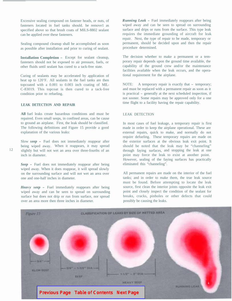
All fuel leaks create hazardous conditions and must berepaired. Even small seeps, in confined areas, can be causeto ground an airplane. First, the leak should be classified.The following definitions and Figure 15 provide a goodexplanation of the various leaks:
12
Slow seep - Fuel does not immediately reappear afterbeing wiped away. When it reappears, it may spreadslightly but will not wet an area over three-fourths of aninch in diameter.
Seep - Fuel does not immediately reappear after beingwiped away. When it does reappear, it will spread slowlyon the surrounding surface and will not wet an area overone and one-half inches in diameter.
Heavy seep - Fuel immediately reappears after beingwiped away and can be seen to spread on surroundingsurface but does not drip or run from surface, nor spreadover an area more then three inches in diameter.
Running Leak - Fuel immediately reappears after beingwiped away and can be seen to spread on surroundingsurface and drips or runs from the surface. This type leakrequires the immediate grounding of aircraft for leakrepair. Next, the type of repair to be made, temporary orpermanent, should be decided upon and then the repairprocedure determined.
The decision whether to make a permanent or a tem-porary repair depends upon the ground time available, thecapability of the ground crew and/or the maintenancefacilities available when the leak occurs, and the opera-tional requirement for the airplane.
NOTE: A temporary repair is exactly that - temporary;and must be replaced with a permanent repair as soon as itis practical - generally at the next scheduled inspection, ifnot sooner. Some repairs may be approved only for a onetime flight to a facility having the repair capability.
LEAK DETECTION
In most cases of fuel leakage, a temporary repair is firstmade in order to keep the airplane operational. These areexternal repairs, quick to make, and normally do notrequire defueling. These temporary repairs are made onthe exterior surfaces at the obvious leak exit point. Itshould be noted that the leak may be “channeling”through faying surfaces,and stopping the leak at onepoint may force the leak to exist at another point.However, sealing of the faying surfaces has practicallyeliminated this “channeling”.
All permanent repairs are made on the interior of the fueltanks; and in order to make them, the true leak sourcemust be found. Before attempting to locate the leaksource, first clean the interior joints opposite the leak exitpoint and closely inspect the condition of the sealant forbreaks, cracks, pinholes or other defects that couldpossibly be causing the leaks.
There are several methods of determining the leak source;however, the simplest and most widely used is the “blowback” method. In this method, compressed air (approxi-mately 70 - 100 psi) is directed at the leak exit point(about an inch away from the fastener) while a co-workerinside the tank is applying a non-corrosive bubble solutionto the joints and fastener patterns opposite the generalarea of the leak. Bubbles will indicate the leak source.
Remove the solution prior to making sealant repairs, andrepeat the test after the repairs are completed to ensurethat they have been effective. Again, remove the solutionprior to refueling the aircraft.
Some other methods used for locating leak sources are asfollows:
Dye injection from outside, using Oil Red “0” dyemixed with fuel (one ounce dye per 100 gallons fuel),or Zyglo ZL-22 mixed one part to ten parts fuel. Thislatter dye is fluorescent and requires an ultraviolet lightfor detection. Some methods utilize pressure on theoutside to inject the dyed fluid through the leak path,while other methods utilize a light vacuum in the tankto draw the dyed fluid into the tank.
In all cases, once a repair has been made, the leak testshould be repeated to ensure that an effective repair wasmade, prior to refueling the airplane.
LEAK REPAIRS
There are several different temporary repair methods forrepairing leaky fasteners. Some are listed below:
Aluminum foil repair method (dime/dollar patch)
Pressure adapter method (for injecting sealant aroundleaky fasteners)
Comp-Air tool number D236 (for injecting Lot-titearound leaky fasteners)
9-L-Stop-A-Leak
Oyltite Stick@
The most effective of the temporary repair methods is thefirst one listed, the aluminum foil repair method (SemcoNo. 400A kit); and the least effective is the last one, theOyltite Stick. The procedure for making these temporaryrepairs is quite simple and is not covered in this article.
Permanent repairs, properly accomplished, should elimi-nate the leak and prevent recurrence. The first step is tolocate the true leak source inside the tank. If the leak is
at a fastener, it should be closely inspected to determinethat the fastener is sound. Unfortunately, there is nopractical way of determining if a fastener was properlyinstalled, if the hole was properly prepared, and of thecorrect size. Only a visible defect or looseness make itapparent that a fastener is unsound. Often, it is better toremove a suspect fastener and to replace it with oneproperly installed than to remove all the sealant around anexisting fastener, reseal it, and still not cure the leak.Difficult to replace Taper-Loks represent exceptions ifthey are sound structurally.
If the fastener is not removed, the old sealant should becut away using a sharp plastic (phenolic) tool and the areashould then be cleaned using clean rags and clean solvent(trichloroethane, 0-T-620, or Methylethylketone,TT-M-261). In order to promote optimum adhesion ofsealant to polyurethane (MIL-C-27725) coated surfaces, afinal wiping with clean rags dampened with PR146 orPR148 (Products Research Corporation) cleaner primer isrecommended. Fasteners should be overcoated with twocoats of MIL-S-8802, Class A sealant. If time permits, thefirst coat of sealant should be cured to a tack-free statebefore application of the second coat. If time does notpermit, inspect the applied brush coat one hour after thefirst coat application for voids, pinholes or thin spots; andapply a second coat over the wet first coat, repairing alldefects. After tack-free cure of the brush sealant, thesealant should bc top-coated with MIL-C-83019 flexiblepolyurethane. This flexible polyurethane coating shouldbe brush applied over all repair sealant, but should notextend over the MIL-C-27725 polyurethane tank coatingfor more than a fraction of an inch. This top coating hasexcellent adhesion to sealant and protects the sealantfrom degradation (chalking) by the fuel; however, itsadhesion to the polyurethane tank coating is marginal,After curing of the top coating to a tack-free condition,the tank may be refueled.
If a leaky fastener is removed, the fastener hole should becleaned of all residual sealant using a safety solvent andpure bristle brushes.A homemade phenolic cutter in adrill motor works very well in removing the sealantaround the hole. The new fastener should be “wet-in-stalled” with sealant. The hole should be checked todetermine if it has the proper clearance or interferencerequired for the fastener being installed. If the hole doesnot have the proper dimension, the fastener is likely toleak again. Lubricants applied on some fastener pins orcollars by the manufacturer (cetyl alcohol or lauric acid)should not be removed. All other contamination shouldbe removed. After wet-installation, the excess sealantsqueeze-out on the inside of the fuel tanks should beremoved to permit the proper brush coating of thefastener with MIL-S-8802, Class A.
NOTE: Do not use zinc-chromate inside a fuel tank.
14
Your Hercules Structural Repair Instruction manualshould be referred to for more definitive instructions onfastener selection, replacement, and repairs.
SUMMARY
To conclude, if fuel is leaking at a fastener installation, itmay be a warning that the fastener is not performing itsprimary structural function of carrying the loads inducedinto the structure. Extensive testing of structural fastenersystems used in the C-130 Hercules wingbox indicates thatwhen these fasteners are properly wet-installed in properlyprepared holes, they will not leak. Although the brushovercoat of sealant, alone, is capable of temporarilystopping a fuel leak from around a defective fastener, ithas been proven both in laboratory tests and by in-serviceexperience that improperly installed fasteners can leak ifthe post-assembly brush seal is defective.
Properly installed fasteners are necessary to ensure thatthe wing attains its specified fatigue life goal.
Temporary repairs,although expedient to keep an air-plane operational, should be replaced with permanentrepairs as soon as practical; otherwise, the leakage rate will
continue to increase - all the old leaks plus developingnew leaks. One leak, temporarily repaired fifteen times isrecorded as fifteen leaks. If permanently repaired, theleak would have been eliminated, and considerable costssaved.
Reference:
C U S T O M E R
Commerc ia lOpera tors
U.S. AirForce
T I T L E A N DD E S I G N A T I O N
Structural Repair Instructions
SMP583 Sec t ion 51
Structural Repair Instructions
T.O. 1 C-l 30A-3 Technical
Manua l
Preparation, Inspection and
Repair of Aircraft Fuel,
Oil and Water Alcohol Cells
and Integral Tanks T.O. l- l-3
U.S. Navy Structural Repair Instructions
NAVAI R 01-75GAA-3
Technical Manual
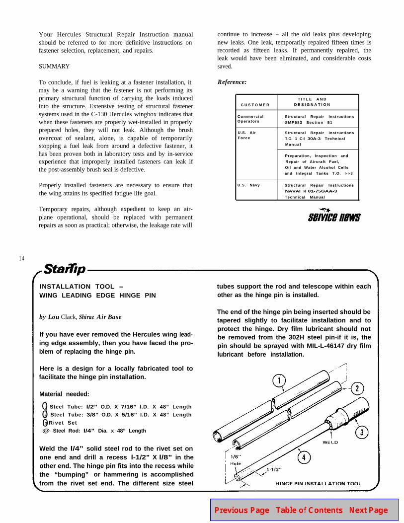
INSTALLATION TOOL -WING LEADING EDGE HINGE PIN
tubes support the rod and telescope within eachother as the hinge pin is installed.
by Lou Clack, Shiraz Air Base
If you have ever removed the Hercules wing lead-ing edge assembly, then you have faced the pro-blem of replacing the hinge pin.
The end of the hinge pin being inserted should betapered slightly to facilitate installation and toprotect the hinge. Dry film lubricant should notbe removed from the 302H steel pin-if it is, thepin should be sprayed with MIL-L-46147 dry filmlubricant before installation.
Here is a design for a locally fabricated tool tofacilitate the hinge pin installation.
Material needed:
01 Steel Tube: l/2” O.D. X 7/16” I.D. X 48” Length
02 Steel Tube: 3/8” O.D. X 5/16” I.D. X 48” Length
03 Rivet Set
@ Steel Rod: l/4” Dia. x 48” Length
Weld the l/4” solid steel rod to the rivet set onone end and drill a recess l-1/2” X l/8” in theother end. The hinge pin fits into the recess whilethe “bumping” or hammering is accomplishedfrom the rivet set end. The different size steel
REPAIR OF RUBBERCOVERING ON In f l ight
The following procedure may be used to repair the rubbercovering on inflight refueling hose assemblies when thedamage is limited to abrasions, cuts, or holes no largerthan a dime in the exterior cover of P/N 149D5009 hoseassemblies. This repair procedure is to be used only ifthe braided wire reinforcement of the hose shows noevidence of damage.
Repair as follows:
1. Remove any loose cover material and lightly bevelthe damaged cover surface to about l/2 inch outfrom the damaged area, using 400 grit abrasive sheet.
2. Wipe the abraded area with clean cloths dampenedwith 0-T-620 Trichloroethane and wipe dry with aclean cloth prior to solvent evaporation.
3. Mix polyurethane adhesive in accordance with themanufacturer’s instructions and apply a sufficientquantity to the hose cover to completely fill andsmooth the damaged area.
NOTE: Pot life of the mixed adhesive is one hourat 75’F and all applications of the adhesive must becompleted within this period.
New Check ValveSPECIFIED
for Hercules Hydraulic Pump Pressure Lines
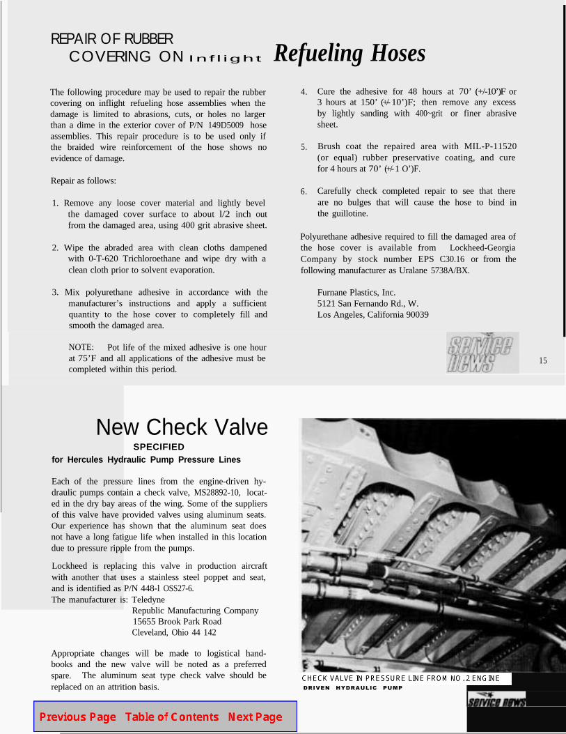
Each of the pressure lines from the engine-driven hy-draulic pumps contain a check valve, MS28892-10, locat-ed in the dry bay areas of the wing. Some of the suppliersof this valve have provided valves using aluminum seats.Our experience has shown that the aluminum seat doesnot have a long fatigue life when installed in this locationdue to pressure ripple from the pumps.
Lockheed is replacing this valve in production aircraftwith another that uses a stainless steel poppet and seat,and is identified as P/N 448-l OSS27-6.The manufacturer is: Teledyne
Republic Manufacturing Company15655 Brook Park RoadCleveland, Ohio 44 142
Appropriate changes will be made to logistical hand-books and the new valve will be noted as a preferredspare. The aluminum seat type check valve should bereplaced on an attrition basis.
Refueling Hoses4.
5.
6.
Cure the adhesive for 48 hours at 70’ (+/-10’)F or3 hours at 150’ (+/- 10’)F; then remove any excessby lightly sanding with 400~grit or finer abrasivesheet.
Brush coat the repaired area with MIL-P-11520(or equal) rubber preservative coating, and curefor 4 hours at 70’ (+/- 1 O’)F.
Carefully check completed repair to see that thereare no bulges that will cause the hose to bind inthe guillotine.
Polyurethane adhesive required to fill the damaged area ofthe hose cover is available from Lockheed-GeorgiaCompany by stock number EPS C30.16 or from thefollowing manufacturer as Uralane 5738A/BX.
Furnane Plastics, Inc.5121 San Fernando Rd., W.Los Angeles, California 90039
15
CHECK VALVE IN PRESSURE LINE FROM NO. 2 ENGINE
DRIVEN HYDRAULIC PUMP
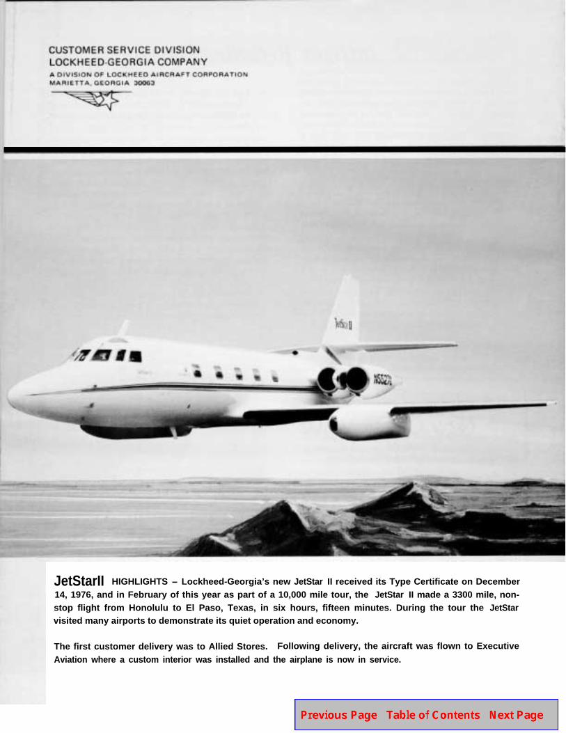
JetStarII HIGHLIGHTS - Lockheed-Georgia’s new JetStar II received its Type Certificate on December14, 1976, and in February of this year as part of a 10,000 mile tour, the JetStar II made a 3300 mile, non-stop flight from Honolulu to El Paso, Texas, in six hours, fifteen minutes. During the tour the JetStarvisited many airports to demonstrate its quiet operation and economy.
The first customer delivery was to Allied Stores. Following delivery, the aircraft was flown to Executive
Aviation where a custom interior was installed and the airplane is now in service.