Embed Size (px)
Citation preview
Lock-Strip GLazinG GaSket curtain WaLLS – HoW oLd iS too oLd?
Matthew C. FarMer, Pe, and MiChael a. hebert
Wiss, Janney, eLstner assOciates, inc. 2751 Prosperity Avenue, Ste. 450, Fairfax, VA 22031
Phone: 703-641-4601 • Fax: 703-641-8822 • E-mail: [email protected]
S y m p o S i u m o n B u i l d i n g E n v E l o p E T E c h n o l o g y • o c T o B E r 2 0 1 4 F a r m E r a n d h E B E r T • 1
abStraCt
A lock-strip gasket curtain wall system at a major headquarters building constructed in 1972 contained numerous deficiencies that led to a recommendation to replace the lock-strip gasket system at a cost of approximately $5 million. A second opinion was developed using sampling and testing techniques to perform comparative physical property testing of the original and new gasket material. Detailed structural analyses were also performed to assess the behavior of the gasket glazing system under load. Lastly, load tests were conducted on a full-size section of the curtain wall to assess the criteria for proper installation and determine whether the deficiencies were severe enough to warrant replacement of the entire curtain wall system.
SPeaKer
mattheW c. Farmer, pe – Wiss, Janney, eLstner assOciates, inc.
MATTHEW FARMER first joined the New Jersey office of WJE in 1986. He has served as principal investigator on numerous evaluations of buildings and monuments, concentrating his practice in the area of masonry building enclosure systems engineering, design, investigation, analysis, and repair. Projects have included institutional and commercial, as well as numerous historic landmarks. Farmer is a registered professional engineer in Washington, D.C.; Maryland; and Virginia. He received a bachelor of science degree in architectural engineering, a bachelor of environmental design degree from the University of Colorado, and a masters in civil engineering from Cornell University.
2 • F a r m E r a n d h E B E r T S y m p o S i u m o n B u i l d i n g E n v E l o p E T E c h n o l o g y • o c T o B E r 2 0 1 4
Lock-Strip GLazinG GaSket curtain WaLLS – HoW oLd iS too oLd?
Many façades built since the 1950s employ an innovative two-piece rubber structural gasket system to support window and curtain wall glazing. Referred to as lock-strip gaskets, the gaskets are designed to replace a more rigid metal frame. The gaskets are often integrated with a supporting steel or aluminum structure and used as mullions between glazing panels or to tie glazing into precast concrete wall panels.
While the system offers many ben efits, its success is highly reliant on installation practices. If improperly installed, severely weathered, or damaged during glazing replacement, the system offers no structural redundancy and minimal protection against uncontrolled water penetration. Manufacturers of lock-strip glazing gasket systems typically estimate their useful service life at or around 30 years; however, many of these installations have successfully performed for over 50 years.
So the question is: When should a lock-strip gasket system be replaced? The obvious answer to this question is when it is no longer serviceable or safe to the occupants of the building in which it is employed. But that determination is not typically straightforward; leaks come and go, glass breaks, and it is difficult to determine if reduced performance is a result of material failure or can be addressed by routine maintenance. The timing around the need for replacement can have significant consequences to building owners— from both a tenant management and a financial perspec tive. To replace the lock-strip glazing gasket curtain wall system with an alternate or even in-kind system requires no less than the removal of the building skin— opening up the building interior (and the tenants) to
the exterior environment. Performing this work on an occupied building is slower, less cost-effective, and more disruptive to building operations than it is for new construction or an unoccupied existing building. Performing the work when the building is vacant requires a substantial period of lost use and revenue when capital is most needed. Façade replacements are frequently performed on existing buildings, but all of them present challenges that it would be preferable to avoid, if even for a limited time, to properly plan the project and acquire funding.
The owners of the project discussed herein were presented with just such a choice when they engaged a reputable curtain wall consulting firm to conduct an evaluation of their curtain walls. They concluded that the lock-strip glazing gasket system installed on the numerous buildings of their headquarters campus was in need of replacement, and that imminent glass retainage fail ure was a real concern. Before moving forward on that premise, the owners took appropriate cautions but also decided to perform a more thorough evaluation of the system to determine whether immediate replacement was the only option. The evaluative tech
niques described in this paper were used to demonstrate that the lock-strip glazing gasket system was indeed in need of minor repairs and adjustments, but that overall replacement was not warranted. This resulted in substantial cost savings to the owner, as well as the ability to plan a long-term replacement strategy based on in-situ physical performance, not arbitrary estimates of useful service life.
HISTORY Lock-strip glazing gasket systems were
first introduced for building façades in the 1950s by the General Motors Corporation.
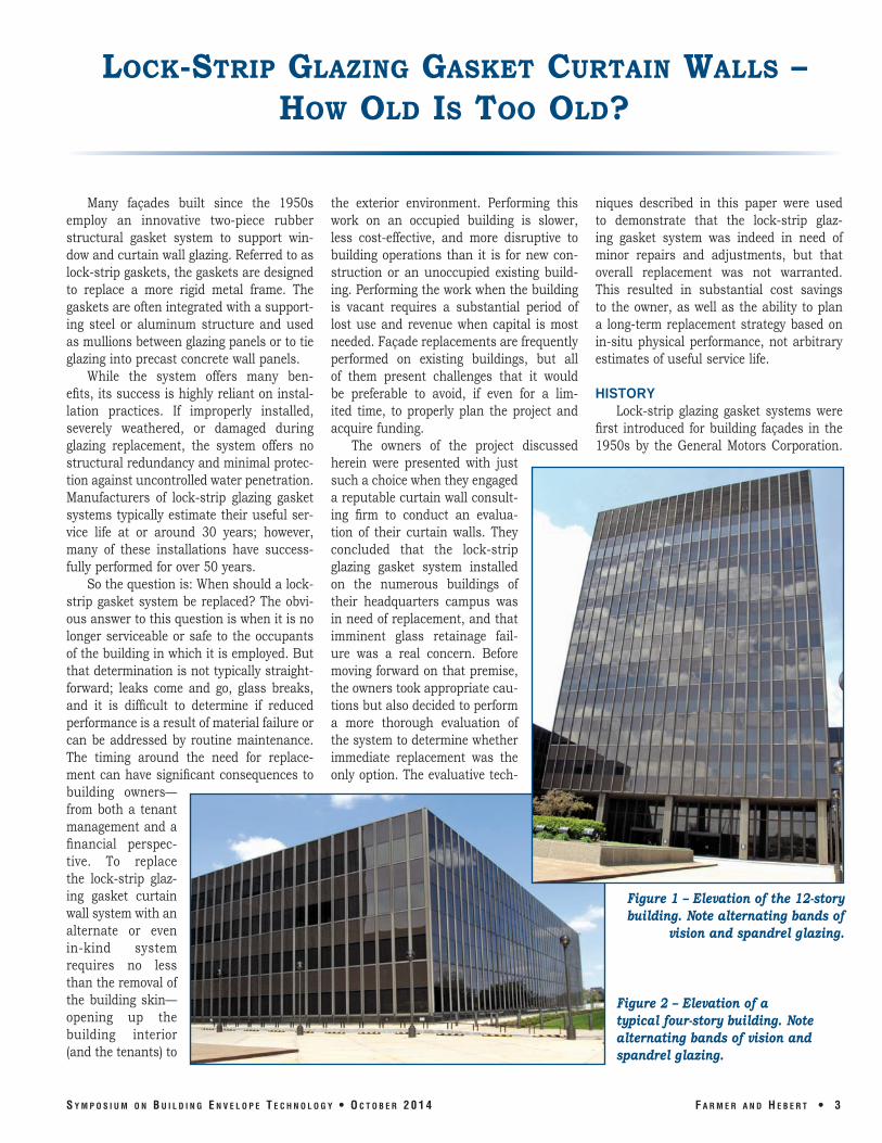
Figure 1 – Elevation of the 12-story building. Note alternating bands of
vision and spandrel glazing.
Figure 2 – Elevation of a typical four-story building. Note alternating bands of vision and spandrel glazing.
S y m p o S i u m o n B u i l d i n g E n v E l o p E T E c h n o l o g y • o c T o B E r 2 0 1 4 F a r m E r a n d h E B E r T • 3
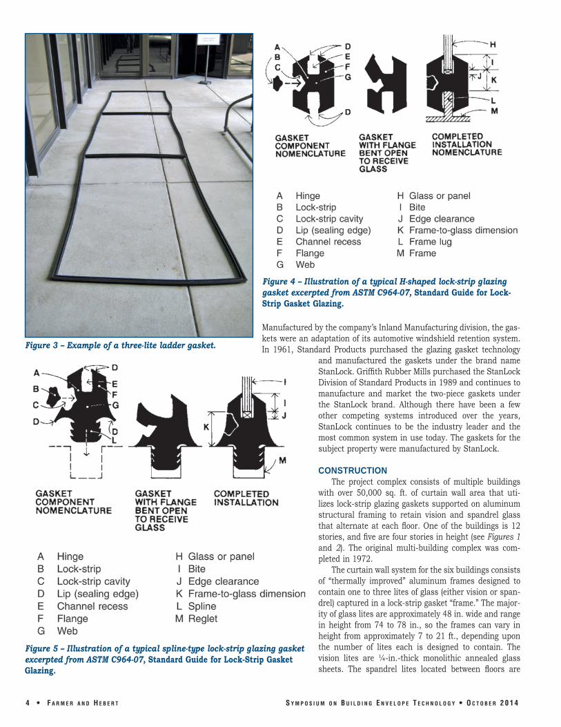
Figure 3 – Example of a three-lite ladder gasket.
Figure 5 – Illustration of a typical spline-type lock-strip glazing gasket excerpted from ASTM C964-07, Standard Guide for Lock-Strip Gasket Glazing.
Figure 4 – Illustration of a typical H-shaped lock-strip glazing gasket excerpted from ASTM C964-07, Standard Guide for Lock-Strip Gasket Glazing.
Manufactured by the company’s Inland Manufacturing division, the gaskets were an adaptation of its automotive windshield retention system. In 1961, Standard Products purchased the glazing gasket technology
and manufactured the gaskets under the brand name StanLock. Griffith Rubber Mills purchased the StanLock Division of Standard Products in 1989 and continues to manufacture and market the two-piece gaskets under the StanLock brand. Although there have been a few other competing systems introduced over the years, StanLock continues to be the industry leader and the most common system in use today. The gaskets for the subject property were manufactured by StanLock.
CONSTRUCTION The project complex consists of multiple buildings
with over 50,000 sq. ft. of curtain wall area that utilizes lock-strip glazing gaskets supported on aluminum structural framing to retain vision and spandrel glass that alternate at each floor. One of the buildings is 12 stories, and five are four stories in height (see Figures 1 and 2). The original multi-building complex was completed in 1972.
The curtain wall system for the six buildings consists of “thermally improved” aluminum frames designed to contain one to three lites of glass (either vision or spandrel) captured in a lock-strip gasket “frame.” The majority of glass lites are approximately 48 in. wide and range in height from 74 to 78 in., so the frames can vary in height from approximately 7 to 21 ft., depending upon the number of lites each is designed to contain. The vision lites are ¼-in.-thick monolithic annealed glass sheets. The spandrel lites located between floors are
4 • F a r m E r a n d h E B E r T S y m p o S i u m o n B u i l d i n g E n v E l o p E T E c h n o l o g y • o c T o B E r 2 0 1 4
also ¼-in. thick monolithic glass, but are treated with an opacifier (an opaque coating applied to the glass to provide reflectivity while preventing visibility of the interior) at the inner surface.
The lock-strip gasket system is a two-piece, preformed, elastomeric mechanical seal used to surround and attach a building panel or glass unit to a supporting structure, and typically is made of metal or concrete. The gasket system consists of the gasket, which captures the edges of the panel or glass unit. It also includes a separate lock strip with a higher durometer hardness that, when forced into a groove provided in the gasket, puts sufficient compression on the gasket lip to secure the panel to the supporting structure and create a “watertight” seal. The lock-strip glazing gasket system is also often referred to as a “zipper gasket,” due to its resemblance to a zipper as the lock strip is installed or removed.
The gaskets are vulcanized into a single continuous rectangle by linking straight extruded sections with injection-molded intersections (corners and “tees”). For larger gaskets designed to accommodate multiple lites, intermediate horizontal gaskets are molded into the perimeter sections, forming a “ladder gasket” (see Figure 3).
The typical lock-strip gasket profile is an H-shape (see Figure 4). This profile is designed to bridge between a building panel and the flange of a supporting structure. H-shape gaskets are used as the perimeter sections of the ladder gaskets to engage the glass lites and the curtain wall frame lugs at the opening perimeter.
The lock-strip gaskets serving as the “rungs” of the ladder configuration are H-shaped to receive two building panels, but also incorporate a spline (similar to the gasket shown in Figure 5) to mechanically engage the supporting structure. The intermediate spline gaskets (Figure 6) engage the top edge of a lower lite and the bottom edge of an upper lite, connecting them to the underlying intermediate aluminum mullion and transferring gravity and lateral loads to the aluminum curtain wall structure. The intermediate aluminum mullions contain a reglet (often serrated) that is specifically sized to receive the spline of the glazing gasket. When used in conjunction with dual-pane insulated glazing units, the spline can be reinforced, or supporting conditions enhanced, to manage the heavier gravity loads.
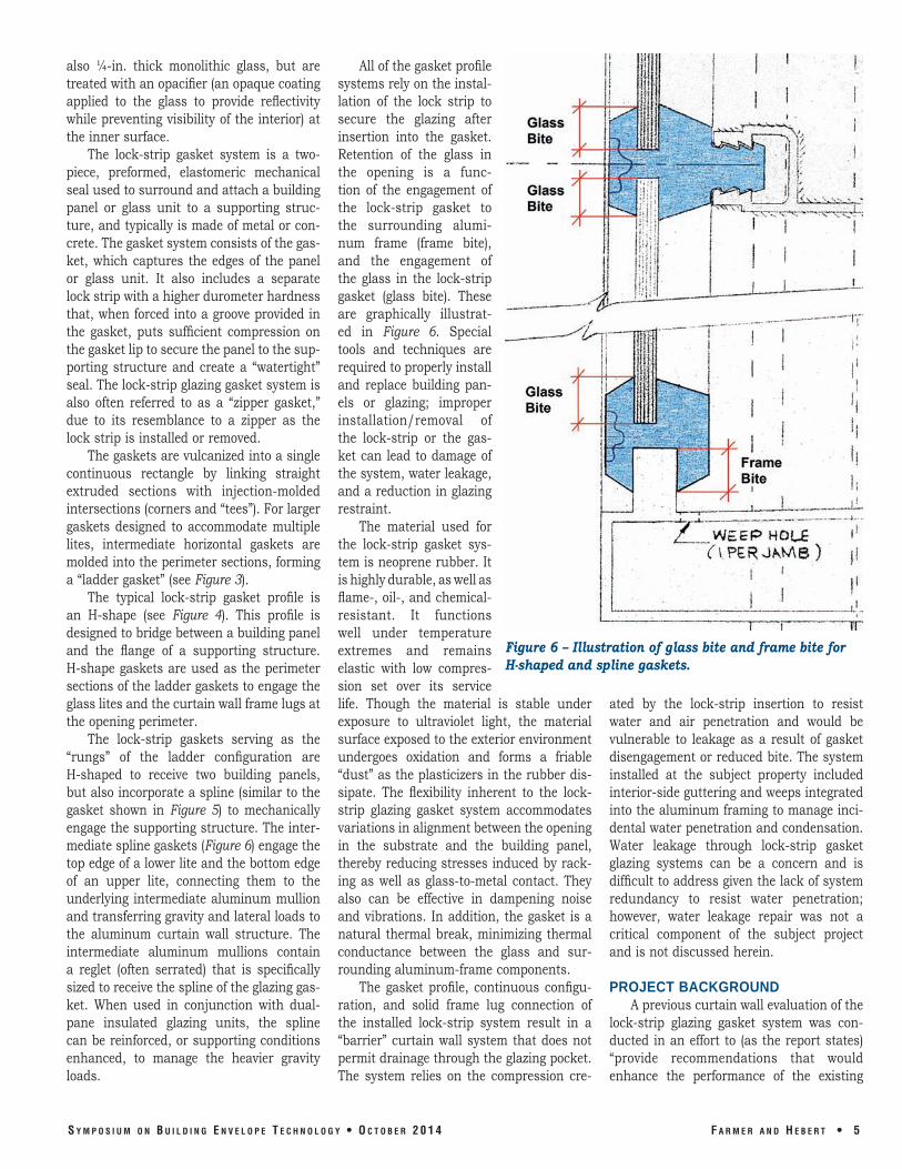
All of the gasket profile systems rely on the installation of the lock strip to secure the glazing after insertion into the gasket. Retention of the glass in the opening is a func tion of the engagement of the lock-strip gasket to the surrounding aluminum frame (frame bite), and the engagement of the glass in the lock-strip gasket (glass bite). These are graphically illustrated in Figure 6. Special tools and techniques are required to properly install and replace building panels or glazing; improper installation/removal of the lock-strip or the gasket can lead to damage of the system, water leakage, and a reduction in glazing restraint.
The material used for the lock-strip gasket system is neoprene rubber. It is highly durable, as well as flame-, oil-, and chemical-resistant. It functions well under temperature extremes and remains elastic with low compres-
Figure 6 – Illustration of glass bite and frame bite for H-shaped and spline gaskets.
sion set over its service life. Though the material is stable under exposure to ultraviolet light, the material surface exposed to the exterior environment undergoes oxidation and forms a friable “dust” as the plasticizers in the rubber dissipate. The flexibility inherent to the lock-strip glazing gasket system accommodates variations in alignment between the opening in the substrate and the building panel, thereby reducing stresses induced by racking as well as glass-to-metal contact. They also can be effective in dampening noise and vibrations. In addition, the gasket is a natural thermal break, minimizing thermal conductance between the glass and surrounding aluminum-frame components.
The gasket profile, continuous configuration, and solid frame lug connection of the installed lock-strip system result in a “barrier” curtain wall system that does not permit drainage through the glazing pocket. The system relies on the compression cre
ated by the lock-strip insertion to resist water and air penetration and would be vulnerable to leakage as a result of gasket disengagement or reduced bite. The system installed at the subject property included interior-side guttering and weeps integrated into the aluminum framing to manage incidental water penetration and condensation. Water leakage through lock-strip gasket glazing systems can be a concern and is difficult to address given the lack of system redundancy to resist water penetration; however, water leakage repair was not a critical component of the subject project and is not discussed herein.
PROJECT BACKGROUND A previous curtain wall evaluation of the
lock-strip glazing gasket system was conducted in an effort to (as the report states) “provide recommendations that would enhance the performance of the existing
S y m p o S i u m o n B u i l d i n g E n v E l o p E T E c h n o l o g y • o c T o B E r 2 0 1 4 F a r m E r a n d h E B E r T • 5
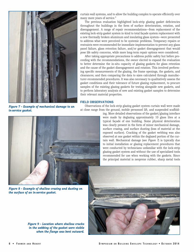
Figure 7 – Example of mechanical damage to an in-service gasket.
curtain wall systems, and to allow the building complex to operate efficiently over many more years of service.”
The previous evaluation highlighted lock-strip glazing gasket deficiencies throughout the buildings in the form of surface deterioration, rotation, and disengagement. A range of repair recommendations—from replacement of the existing lock-strip gasket system in-kind to total façade system replacement with a new thermally broken aluminum and insulating glass system—were presented to address what were perceived to be systemic problems. Temporary repairs or restraints were recommended for immediate implementation to prevent any glass panel failure, glass retention failure, and/or gasket disengagement that would pose life safety concerns, while more long-term repair options were considered.
After taking appropriate precautions to address public safety but before proceeding with the recommendations, the owner elected to expand the evaluation to better determine the in-situ capacity of glazing gaskets for glass retention and the cause of the gasket disengagement and rotation. This involved performing specific measurements of the glazing, the frame openings, the gaskets, and clearances; and then comparing the data to sizes calculated through manufacturer-recommended procedures. It was also necessary to qualitatively assess the gasket conditions and their tolerance of future glazing replacement, to procure samples of the existing glazing gaskets for testing alongside new gaskets, and to perform laboratory analysis of new and existing gasket samples to determine their relevant material properties.
FIELD OBSERVATIONS Observations of the lock-strip glazing gasket system curtain wall were made
at close range from the ground, mobile personnel lift, and suspended scaffolding. More detailed observations of the gasket/glazing interface were made by deglazing approximately 10 glass lites at a typical façade of one building. Some physical deterioration was clearly present in the form of minor mechanical damage, surface crazing, and surface dusting (loss of material at the exposed surface). Cracking of the gasket webbing was also observed at one gasket within the deglazed portion of the curtain wall. Mechanical damage (see Figure 7) is typically due to initial installation or glazing replacement procedures that were conducted by technicians unfamiliar with the lock-strip glazing gasket system and without the use of specialized tools recommended for use when working with the gaskets. Since the principal material is neoprene rubber, sharp metal tools
Figure 8 – Example of shallow crazing and dusting on the surface of an in-service gasket.
Figure 9 – Location where shallow cracks in the webbing of the gasket were visible
when the flange was bent outward.
6 • F a r m E r a n d h E B E r T S y m p o S i u m o n B u i l d i n g E n v E l o p E T E c h n o l o g y • o c T o B E r 2 0 1 4
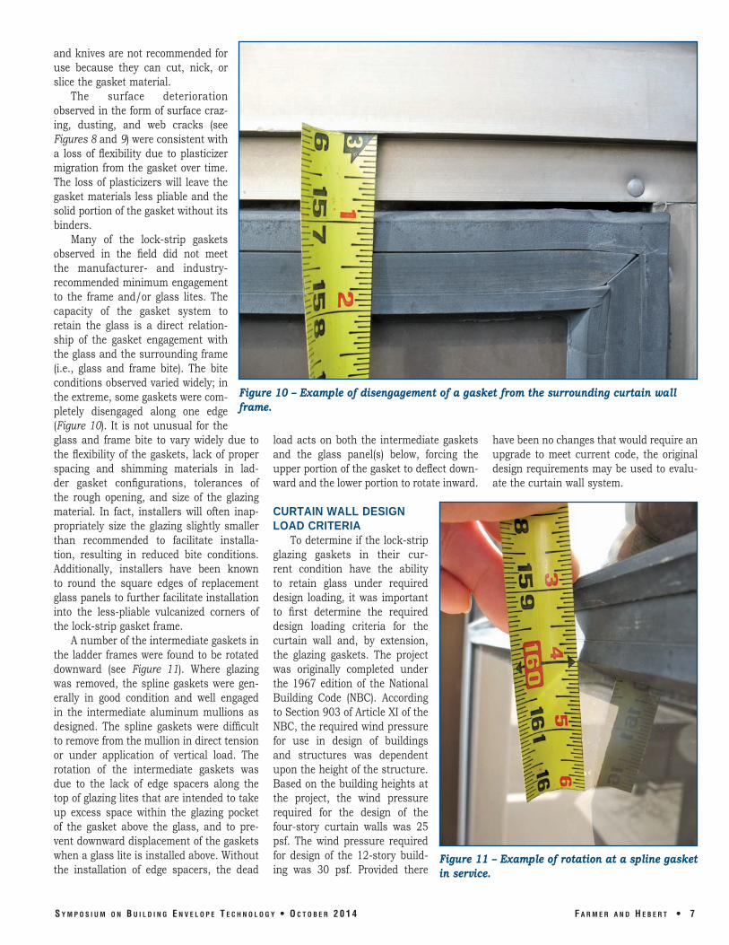
Figure 10 – Example of disengagement of a gasket from the surrounding curtain wall frame.
and knives are not recommended for use because they can cut, nick, or slice the gasket material.
The surface deterioration observed in the form of surface crazing, dusting, and web cracks (see Figures 8 and 9) were consistent with a loss of flexibility due to plasticizer migration from the gasket over time. The loss of plasticizers will leave the gasket materials less pliable and the solid portion of the gasket without its binders.
Many of the lock-strip gaskets observed in the field did not meet the manufacturer- and industry-recommended minimum engagement to the frame and/or glass lites. The capacity of the gasket system to retain the glass is a direct relationship of the gasket engagement with the glass and the surrounding frame (i.e., glass and frame bite). The bite conditions observed varied widely; in the extreme, some gaskets were completely disengaged along one edge (Figure 10). It is not unusual for the glass and frame bite to vary widely due to the flexibility of the gaskets, lack of proper spacing and shimming materials in ladder gasket configurations, tolerances of the rough opening, and size of the glazing material. In fact, installers will often inappropriately size the glazing slightly smaller than recommended to facilitate installa tion, resulting in reduced bite conditions. Additionally, installers have been known to round the square edges of replacement glass panels to further facilitate installation into the less-pliable vulcanized corners of the lock-strip gasket frame.
A number of the intermediate gaskets in the ladder frames were found to be rotated downward (see Figure 11). Where glazing was removed, the spline gaskets were generally in good condition and well engaged in the intermediate aluminum mullions as designed. The spline gaskets were difficult to remove from the mullion in direct tension or under application of vertical load. The rotation of the intermediate gaskets was due to the lack of edge spacers along the top of glazing lites that are intended to take up excess space within the glazing pocket of the gasket above the glass, and to prevent downward displacement of the gaskets when a glass lite is installed above. Without the installation of edge spacers, the dead
load acts on both the intermediate gaskets have been no changes that would require an and the glass panel(s) below, forcing the upgrade to meet current code, the original upper portion of the gasket to deflect down- design requirements may be used to evaluward and the lower portion to rotate inward. ate the curtain wall system.
CURTAIN WALL DESIGN LOAD CRITERIA
To determine if the lock-strip glazing gaskets in their cur rent condition have the ability to retain glass under required design loading, it was important to first determine the required design loading criteria for the curtain wall and, by extension, the glazing gaskets. The project was originally completed under the 1967 edition of the National Building Code (NBC). According to Section 903 of Article XI of the NBC, the required wind pressure for use in design of buildings and structures was dependent upon the height of the structure. Based on the building heights at the project, the wind pressure required for the design of the four-story curtain walls was 25 psf. The wind pressure required for design of the 12-story building was 30 psf. Provided there
Figure 11 – Example of rotation at a spline gasket in service.
S y m p o S i u m o n B u i l d i n g E n v E l o p E T E c h n o l o g y • o c T o B E r 2 0 1 4 F a r m E r a n d h E B E r T • 7
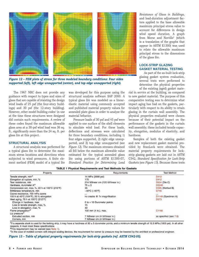
Figure 12 – FEM plots of stress for three modeled boundary conditions: Four sides supported (left), left edge unsupported (center), and top edge unsupported (right).
The 1967 NBC does not provide any guidance with respect to types and sizes of glass that are capable of resisting the design wind loads of 25 psf (the four-story buildings) and 30 psf (the 12-story building). However, other model building codes1 in use at the time these structures were designed did contain such requirements. A review of these codes found the maximum allowable glass area at a 30-psf wind load was 36 sq. ft., significantly more than the 24 sq. ft. per glass lite at this project.
STRUCTURAL ANALYSIS A structural analysis was performed for
a typical glass lite to determine the maximum stress locations and directions when subjected to wind pressures. A finite element method (FEM) model of a typical lite
was developed for this purpose using the structural analysis software SAP 2000. A typical glass lite was modeled as a linear-elastic material using commonly accepted and published material property values for annealed plate glass in order to analyze the material behavior.
Pressure loads of 30 psf and 45 psf were applied to one surface of the shell elements to simulate wind load. For these loads, deflections and stresses were calculated for three boundary conditions, including 1) four edges supported, 2) right edge unsupported, and 3) top edge unsupported (see Figure 12). The maximum stresses obtained all fell below the maximum allowable value estimated for the typical annealed glass lite using portions of ASTM E1300-07, Standard Practice for Determining Load
Resistance of Glass in Buildings, and load-duration adjustment factors applied to the base allowable maximum principal stress value to account for differences in design wind speed duration. A graph from Morse and Norville2 (which is a translation of the graphs that appear in ASTM E1300) was used to relate the allowable maximum principal stress to the dimensions of the glass lite.
LOCK-STRIP GLAZING GASKET MATERIAL TESTING
As part of the as-built lock-strip glazing gasket system evaluation, several tests were performed to determine the physical properties of the existing (aged) gasket mate
rial in service at the building, as compared to new gasket material. The purpose of this comparative testing was to determine what impact aging has had on the gaskets, particularly with respect to its ability to retain glazing in the curtain wall assembly. The physical properties evaluated were chosen because of their potential impact on the performance of the gaskets in the curtain wall assembly; these included tensile capacity, elongation, modulus of elasticity, and hardness.
Samples of both the existing gasket and new replacement gasket material provided by StanLock were obtained. The material property requirements for lock-strip glazing gaskets are laid out in ASTM C542, Standard Specification for Lock-Strip Gaskets (see Figure 13). Because these tests
Figure 13 – Table of physical property requirements for lock-strip gaskets (ref. ASTM C542-05).
8 • F a r m E r a n d h E B E r T S y m p o S i u m o n B u i l d i n g E n v E l o p E T E c h n o l o g y • o c T o B E r 2 0 1 4
are normally conducted on samples of raw material prepared specifically for the testing prior to final product manufacture, it was not possible to exactly match the specimen requirements for specific test standards with the post-manufactured material available; however, since the interest was in the comparative results between new and aged material, modifications to the specimen geometry were acceptable, provided the specimens were prepared identically for the two groups of gasket material.
Figure 14 – Example of disengagement of a gasket from the surrounding curtain wall frame.
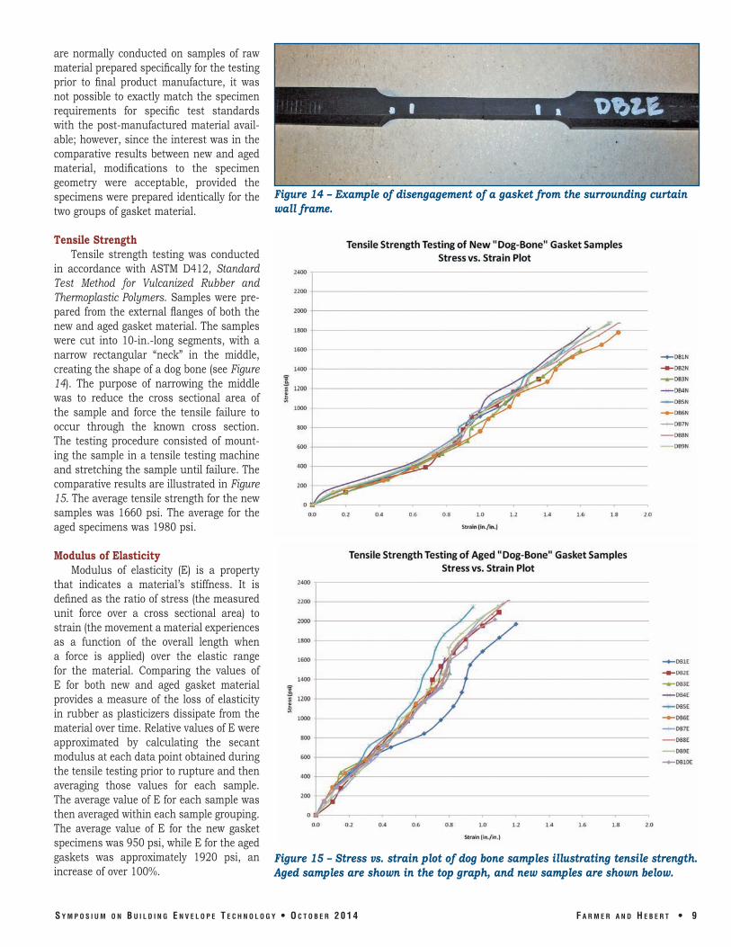
Tensile Strength Tensile strength testing was conducted
in accordance with ASTM D412, Standard Test Method for Vulcanized Rubber and Thermoplastic Polymers. Samples were prepared from the external flanges of both the new and aged gasket material. The samples were cut into 10-in.-long segments, with a narrow rectangular “neck” in the middle, creating the shape of a dog bone (see Figure 14). The purpose of narrowing the middle was to reduce the cross sectional area of the sample and force the tensile failure to occur through the known cross section. The testing procedure consisted of mounting the sample in a tensile testing machine and stretching the sample until failure. The comparative results are illustrated in Figure 15. The average tensile strength for the new samples was 1660 psi. The average for the aged specimens was 1980 psi.
Modulus of Elasticity Modulus of elasticity (E) is a property
that indicates a material’s stiffness. It is defined as the ratio of stress (the measured unit force over a cross sectional area) to strain (the movement a material experiences as a function of the overall length when a force is applied) over the elastic range for the material. Comparing the values of E for both new and aged gasket material provides a measure of the loss of elasticity in rubber as plasticizers dissipate from the material over time. Relative values of E were approximated by calculating the secant modulus at each data point obtained during the tensile testing prior to rupture and then averaging those values for each sample. The average value of E for each sample was then averaged within each sample grouping. The average value of E for the new gasket specimens was 950 psi, while E for the aged gaskets was approximately 1920 psi, an increase of over 100%.
Figure 15 – Stress vs. strain plot of dog bone samples illustrating tensile strength. Aged samples are shown in the top graph, and new samples are shown below.
S y m p o S i u m o n B u i l d i n g E n v E l o p E T E c h n o l o g y • o c T o B E r 2 0 1 4 F a r m E r a n d h E B E r T • 9