Embed Size (px)
Citation preview

phone: (408)744-9040www.thinkSRS.com
Stanford Research Systems
· 0.5 Hz to 100 kHz frequency range
· Current and voltage inputs
· Up to 80 dB dynamic reserve
· Tracking band-pass and line filters
· Internal reference oscillator (opt.)
· Four ADC inputs, two DAC outputs
· RS-232 interface (std.)
· GPIB interface (opt.)
· SR510 ... $2495 (U.S. list)
· SR530 ... $2995 (U.S. list)
The SR510 and SR530 are analog lock-in amplifiers which can measure AC signals as small as nanovolts in the presence of much larger noise levels. Both the single phase SR510 and the dual phase SR530 have low-noise voltage and current inputs, high dynamic reserve, two stages of time constants, and an internal oscillator. In addition, both lock-ins come equipped with a variety of features designed to make them simple to use.
Sine Wave Mixing
The core of the SR510/SR530 is a precision analog sine-wave multiplier. Lock-ins use a multiplier (demodulator) to translate the input signal (at the reference frequency) down to DC where it can be filtered and amplified. Many lock-ins use square wave multipliers which introduce spurious harmonic responses. The SR510/SR530 use clean sine-wave multipliers which are inherently free of unwanted harmonics.
Signal Input
The SR510 and SR530 have differential inputs with 7 nV/√Hz of input noise and 100 MΩ input impedance. The input can be configured as a voltage input, or as a current input with 106 V/A gain and an input impedance of 1 kΩ to virtual ground. Full-scale sensitivities from 500 mV down to 100 nV are available.
Three input prefilters can be selected. The first is a line notch filter providing 50 dB of rejection at the line frequency. The
SR510 & SR530 Lock-In Amplifiers
Lock-In AmplifiersSR510 and SR530 — Lock-in amplifiers
SR530 Lock-In Amplifier
Stanford Research Systems
phone: (408)744-9040www.thinkSRS.com
SR510 and SR530 Lock-In Amplifiers
second filter similarly provides 50 dB of rejection at the second harmonic of the line frequency. The third filter is a band pass filter which automatically tracks the reference frequency. These three filters can eliminate much of the noise in the signal before it is amplified.
Reference Input
The reference input can be set to lock to sine waves or to either edge of a pulsed reference. The reference frequency range is 0.5 Hz to 100 kHz, and detection at both the fundamental and second harmonic of the reference is allowed. A convenient, built-in frequency meter constantly measures and displays the reference frequency with 4-digit resolution. The reference can be phase shifted with 0.025° resolution from the front panel, or shifted in 90° increments for easy measurement of quadrature signals. The SR530 has an auto-phase feature that lets you quickly determine the phase of the signal relative to the reference with a single key-press.
Output Time Constants
Two stages of filtering follow the phase sensitive detector. Time constants can be chosen as long as 100 seconds for maximum noise reduction, or as short as 1 ms (20 µs with modification) for use in real-time servo loops. The two filter stages allow a rolloff of 6 or 12 dB/octave.
Dynamic Reserve
The dynamic reserve of a lock-in amplifier, at a given full-scale input voltage, is the ratio (in dB) of the largest interfering signal to the full-scale input voltage. The largest interfering signal is defined as the amplitude of the largest signal at any frequency that can be applied to the input before the lock-in cannot measure a signal with its specified accuracy.
The SR510 and SR530 have a dynamic reserve of between 20 dB and 60 dB, depending on the sensitivity scale. Selecting the band pass filter adds an additional 20 dB of dynamic reserve, making the maximum dynamic reserve for these lock-ins 80 dB.
Offset and Expand
The SR510/SR530’s offset and expand features make it easy to look at small changes in a large signal. Output offset of 0 to 100 % of full scale can be selected manually or by using auto-offset, which automatically selects an offset equal to the signal value. Once the signal is offset, a 10× expand is available to provide increased resolution when looking at small changes from a nominal value.
Analog and Digital Displays
Precision analog meters and 4-digit digital displays are standard on both lock-ins. On the SR510, you can select displays of the signal amplitude, the signal offset, or the measured noise. On the SR530, the first pair of displays show the signal components in rectangular form (X and Y), polar form (R and θ), the offset, noise, or the value of the rear-panel D/A outputs. The other digital display on both lock-ins can be configured to show either the reference phase or the reference frequency.
Noise Measurement
The SR510/SR530’s noise measurement feature lets you directly measure the noise in your signal at the reference frequency. Noise is defined as the rms deviation of the signal from its mean. The SR510/SR530 will report the value of the noise in both a 1 Hz and 10 Hz bandwidth around the reference frequency.
Internal Oscillator
An optional internal voltage-controlled oscillator provides both an adjustable-amplitude sine wave output and a synchronous, fixed-amplitude reference output. The sine wave amplitude can be set to 0.01, 0.1 or 1 Vrms, and can drive up to 20 mA. The oscillator frequency is controlled by a rear-panel voltage input and can be adjusted between 1 Hz and 100 kHz. Typically, the sine wave output is used to excite some aspect of an experiment, while the reference output provides a frequency reference to the lock-in.
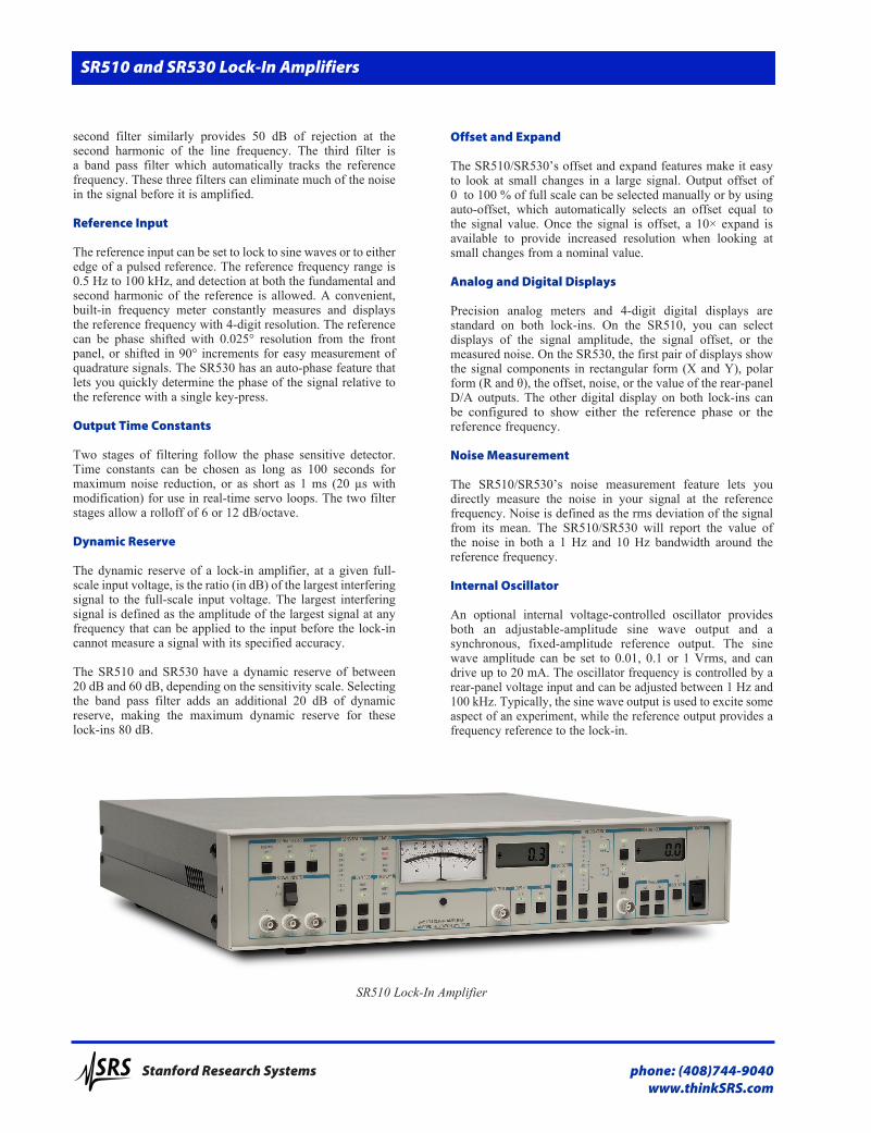
SR510 Lock-In Amplifier

phone: (408)744-9040www.thinkSRS.com
Stanford Research Systems
A/Ds and D/As
There are four A/Ds and two D/As on the rear panel that provide flexibility in interfacing the SR510/SR530 with external signals. These input/output ports measure and supply analog voltages with a range of ±10.24 VDC and a resolution of 2.5 mV. The A/Ds digitize signals at a rate of 1 kHz. The D/A output is ideal for controlling the frequency of the SR510/530’s internal voltage-controlled oscillator. A built-in ratio feature allows the SR510/SR530 to calculate the ratio of its output to a signal at one of the A/D ports. This feature is important in servo applications to maintain a constant loop gain, or in experiments that normalize a signal to an intensity level.
Available Preamplifiers
Although the SR510 and SR530 are completely self contained and require no preamplification, sometimes an external preamplifier can be useful. Remote preamplifiers provide gain where it’s most important—right at the detector, before the signal-to-noise ratio is permanently degraded by cable noise and pickup. The SR550 FET-input preamplifier, the SR552 bipolar-input preamplifier, and the SR554 transformer-input preamplifier are ideally suited for use with the SR510/SR530 lock-ins. These preamplifiers are especially useful when measuring extremely low-level signals.
Computer Interfaces
An RS-232 computer interface is standard on both the SR510 and SR530. An optional GPIB interface is also available. All features of the instruments can be queried and set via the computer interfaces.
SR510 and SR530 Lock-In Amplifiers
Ordering InformationSR510 Single phase lock-in $2495 amplifier (w/ rack mount) SR530 Dual phase lock-in $2995 amplifier (w/ rack mount) Option 01 GPIB interface for SR510/SR530 $995Option 02 Internal oscillator $995SR550 Voltage preamplifier $750 (100 MΩ, 3.6 nV/√Hz) SR552 Voltage preamplifier $750 (100 kΩ, 1.4 nV/√Hz) SR554 Transformer preamplifier $1200 (0.091 nV/√Hz) SR555 Current preamplifier $1095SR556 Current preamplifier $1095SR540 Optical chopper $1195
SR510 and SR530 rear panels (with Opt. 01 & Opt. 02)
Stanford Research Systems
phone: (408)744-9040www.thinkSRS.com
SR510 and SR530 Specifications
Signal Channel
Inputs Voltage Single-ended or differential Current 106 V/AImpedance Voltage 100 MΩ + 25 pF, AC coupled Current 1 kΩ to virtual groundFull-scale sensitivity Voltage 100 nV to 500 mV Current 100 fA to 0.5 µA Maximum inputs Voltage 100 VDC, 10 VAC damage threshold, 2 Vpp saturation Current 10 µA damage threshold, 1 µApp saturationNoise Voltage 7 nV/√Hz at 1 kHz (typ.) Current 0.13 pA/√Hz at 1 kHz (typ.)Common Mode Range 1 Vp Rejection 100 dB (DC to 1 kHz, degrades by 6 dB/oct above 1 kHz)Gain accuracy 1 % (2 Hz to 100 kHz)Gain stability 200 ppm/°CSignal filters 60 Hz notch, –50 dB (Q = 10, adjustable from 45 Hz to 65 Hz) 120 Hz notch, –50 dB (Q = 10, adjustable from 100 Hz to 130 Hz) Tracking band pass (Q = 5). Filter adds 20 dB to dynamic reserve. Dynamic reserve LOW (20 dB), 5 ppm/°C (1 µV to 500 mV sensitivity) NORM (40 dB), 50 ppm/°C (100 nV to 50 mV sensitivity) HIGH (60 dB), 500 ppm/°C (100 nV to 5 mV sensitivity)Reference Channel
Frequency 0.5 Hz to 100 kHzInput impedance 1 MΩ, AC coupledTrigger Sine 100 mV minimum, 1 Vrms nominal Pulse ±1 V, 1 µs minimum widthMode Fundamental (f), 2nd harmonic (2f)Acquisition time 25 s (1 Hz ref.), 6 s (10 Hz ref.), 2 s (10 kHz ref.)Slew rate 1 decade per 10 s at 1 kHzPhase control 90° shifts, fine shifts in 0.025° stepsPhase noise 0.01° rms at 1 kHz (100 ms, 12 dB/oct rolloff time constant)Phase drift 0.1°/°CPhase error Less than 1° above 10 HzOrthogonality* 90° ± 1°
Demodulator
Stability 5 ppm/°C (LOW reserve) 50 ppm/°C (NORM reserve) 500 ppm/°C (HIGH reserve) Time constants Pre 1 ms to 100 s (6 dB/octave) Post 1 s, 0.1 s, none (6 dB/octave)Offset Up to 1× full scale (10× on expand)Harmonic rejection –55 dB (band pass filter in)
Outputs and Interfaces Channel 1 outputs X (Rcosθ), X Offset, X Noise, R*, R Offset*, X5 (ext. D/A)*Channel 2 outputs* Y (Rsinθ), Y offset, θ, Y noise, X6 (ext. D/A)Output meters 2 % precision analog meterOutput LCD 4-digit LCD display shows same value as the analog meter.Output BNC ±10 V corresponds to full-scale input (<1 Ω output impedance)Reference output 4-digit LCD display for reference phase or frequencyX1 to X4 4 analog inputs, 13-bit, ±10.24 VX5, X6 2 analog outputs, 13-bit, ±10.24 VX output* X (Rcosθ), ±10 V, <1 Ω output impedanceY output* Y (Rsinθ), ±10 V, <1 Ω output impedanceRatio Ratio output equals 10× signal output divided by the denominator of the input.Internal oscillator Range 1 Hz to 100 kHz Accuracy 10 % Stability 150 ppm/°C (frequency) 500 ppm/°C (amplitude) Distortion 2 % THD Amplitude 10 mVrms, 100 mVrms, 1 VrmsComputer interfaces RS-232 standard, GPIB optional. All instrument functions can be controlled and read through the interfaces. General Power 35 W, 100/120/220/240 VAC, 50/60 HzDimensions (SR510) 17" × 3.5" × 17" (WHD) (SR530) 17" × 5.25" × 17" (WHD)Weight 12 lbs. (SR510), 16 lbs. (SR530)Warranty One year parts and labor on defects in materials and workmanship
* SR530 only


![Fast backprojection-based reconstruction of spectral ... · application of Zeeman field modulation or lock-in amplifiers [19-21]. Although this technique looks very promising for](https://img.pdfslide.us/doc/110x75/5f47926a8b500f5ac84735da/fast-backprojection-based-reconstruction-of-spectral-application-of-zeeman-field.jpg)