Embed Size (px)
Citation preview
Locator ID Separation Protocol (LISP) VM Mobility Solution
White Paper

NOTICE. ALL STATEMENTS, INFORMATION, AND RECOMMENDATIONS IN THIS MANUAL ARE BELIEVED TO BE ACCURATE BUT ARE PRESENTED WITHOUT WARRANTY OF ANY KIND, EXPRESS OR IMPLIED. USERS MUST TAKE FULL RESPONSIBILITY FOR THEIR APPLICATION OF ANY PRODUCTS. THE SOFTWARE LICENSE AND LIMITED WARRANTY FOR THE ACCOMPANYING PRODUCT ARE SET FORTH IN THE INFORMATION PACKET THAT SHIPPED WITH THE PRODUCT AND ARE INCORPORATED HEREIN BY THIS REFERENCE. IF YOU ARE UNABLE TO LOCATE THE SOFTWARE LICENSE OR LIMITED WARRANTY, CONTACT YOUR CISCO REPRESENTATIVE FOR A COPY. The Cisco implementation of TCP header compression is an adaptation of a program developed by the University of California, Berkeley (UCB) as part of UCB's public domain version of the UNIX operating system. All rights reserved. Copyright © 1981, Regents of the University of California. NOTWITHSTANDING ANY OTHER WARRANTY HEREIN, ALL DOCUMENT FILES AND SOFTWARE OF THESE SUPPLIERS ARE PROVIDED "AS IS" WITH ALL FAULTS. CISCO AND THE ABOVE-NAMED SUPPLIERS DISCLAIM ALL WARRANTIES, EXPRESSED OR IMPLIED, INCLUDING, WITHOUT LIMITATION, THOSE OF MERCHANTABILITY, FITNESS FOR A PARTICULAR PURPOSE AND NONINFRINGEMENT OR ARISING FROM A COURSE OF DEALING, USAGE, OR TRADE PRACTICE. IN NO EVENT SHALL CISCO OR ITS SUPPLIERS BE LIABLE FOR ANY INDIRECT, SPECIAL, CONSEQUENTIAL, OR INCIDENTAL DAMAGES, INCLUDING, WITHOUT LIMITATION, LOST PROFITS OR LOSS OR DAMAGE TO DATA ARISING OUT OF THE USE OR INABILITY TO USE THIS MANUAL, EVEN IF CISCO OR ITS SUPPLIERS HAVE BEEN ADVISED OF THE POSSIBILITY OF SUCH DAMAGES. CCDE, CCENT, Cisco Eos, Cisco Lumin, Cisco Nexus, Cisco StadiumVision, Cisco TelePresence, Cisco WebEx, the Cisco logo, DCE, and Welcome to the Human Network are trademarks; Changing the Way We Work, Live, Play, and Learn and Cisco Store are service marks; and Access Registrar, Aironet, AsyncOS, Bringing the Meeting To You, Catalyst, CCDA, CCDP, CCIE, CCIP, CCNA, CCNP, CCSP, CCVP, Cisco, the Cisco Certified Internetwork Expert logo, Cisco IOS, Cisco Press, Cisco Systems, Cisco Systems Capital, the Cisco Systems logo, Cisco Unity, Collaboration Without Limitation, EtherFast, EtherSwitch, Event Center, Fast Step, Follow Me Browsing, FormShare, GigaDrive, HomeLink, Internet Quotient, IOS, iPhone, iQuick Study, IronPort, the IronPort logo, LightStream, Linksys, MediaTone, MeetingPlace, MeetingPlace Chime Sound, MGX, Networkers, Networking Academy, Network Registrar, PCNow, PIX, PowerPanels, ProConnect, ScriptShare, SenderBase, SMARTnet, Spectrum Expert, StackWise, The Fastest Way to Increase Your Internet Quotient, TransPath, WebEx, and the WebEx logo are registered trademarks of Cisco Systems, Inc. and/or its affiliates in the United States and certain other countries. All other trademarks mentioned in this document or website are the property of their respective owners. The use of the word partner does not imply a partnership relationship between Cisco and any other company. (0809R) Copyright © 2011 Cisco Systems, Inc. All rights reserved.
Contents
Introduction ............................................................................................................................................ 1 IP Mobility Overview .........................................................................................................................................2
IP Mobility Requirements ......................................................................................................................................... 2 Existing IP Mobility Solutions .................................................................................................................................... 3
Document Use Prerequisite ...............................................................................................................................6 LISP Name Spaces: .................................................................................................................................................... 6 LISP Site Devices: ....................................................................................................................................................... 6 LISP Infrastructure Devices: ...................................................................................................................................... 7
LISP VM-Mobility .................................................................................................................................... 8
LISP VM-Mobility Use Cases .................................................................................................................. 10 LISP VM-Mobility Prerequisites ....................................................................................................................... 11
LISP VM-Mobility Operation .................................................................................................................. 13 Dynamic-EID Detection and Map Update ......................................................................................................... 14 Map-Server and Map-Resolver Consideration .................................................................................................. 16
Deploying LISP VM-Mobility within an Extended Subnet ........................................................................ 18 LISP VM-Mobility within an Extended Subnet Prerequisites .............................................................................. 19 Configuring a Cisco Nexus 7000 Switch as a LISP xTR ........................................................................................ 19
Configuration Steps ................................................................................................................................................. 19 Configuring a Cisco Nexus 7000 Switch LISP xTR for Dynamic-EID Roaming ....................................................... 21
Configuration Steps ................................................................................................................................................. 21 Configuring a Remote Site Cisco IOS Router as a LISP xTR ................................................................................. 24
Configuration Steps ................................................................................................................................................. 24 Configuring a LISP Map-Server and Resolver on NX-OS ..................................................................................... 26
Configuration Steps ................................................................................................................................................. 26 LISP VM-Mobility within an Extended Subnet: Configuration Example .............................................................. 28
Nexus 7000 N7K1A West DC-xTR Configuration Example ...................................................................................... 29 Nexus 7000 N7K1B West DC-xTR Configuration Example ...................................................................................... 29 Nexus 7000 N7K2A East DC-xTR Configuration Example ........................................................................................ 30 Nexus 7000 N7K2B East DC-xTR Configuration Example ........................................................................................ 31 Remote Site Cisco IOS-xTR Configuration Example ................................................................................................ 31 NX-OS Map-Server and Map-Resolver Configuration Example .............................................................................. 32
LISP VM-Mobility within an Extended Subnet Verification Steps ....................................................................... 33 Verifying an NX-OS Map-Server .............................................................................................................................. 34 Verifying Nexus 7000 DC-xTRs ................................................................................................................................ 35 Verifying Cisco IOS Remote xTR .............................................................................................................................. 37 Verifying Dynamic-EID Detection, Mapping and Map-Cache Update ................................................................... 39
Summary ........................................................................................................................................................ 43
Deploying LISP VM-Mobility across Subnet ............................................................................................ 44 LISP VM-Mobility across Subnet Prerequisites.................................................................................................. 45 Configuring a Cisco Nexus 7000 Switch as a LISP xTR ........................................................................................ 45
Configuration Steps ................................................................................................................................................. 45 Configuring a Cisco Nexus 7000 Switch LISP xTR for Dynamic-EID Roaming ....................................................... 47
Configuration Steps ................................................................................................................................................. 47
Configuring the Remote Site Cisco IOS Router as a LISP xTR .............................................................................. 50 Configuration Steps ................................................................................................................................................. 50
Configuring the LISP Map-Server and Resolver on NX-OS .................................................................................. 52 Configuration Steps ................................................................................................................................................. 52
LISP VM-Mobility Across Subnet: Configuration Example ................................................................................. 53 Nexus 7000 N7K1A West DC-xTR Configuration Example ...................................................................................... 55 Nexus 7000 N7K1B West DC-xTR Configuration Example ...................................................................................... 55 Nexus 7000 N7K2A East DC-xTR Configuration Example ........................................................................................ 56 Nexus 7000 N7K2B East DC-xTR Configuration Example ........................................................................................ 57 Remote Site Cisco IOS-xTR Configuration Example ................................................................................................ 57 NX-OS Map-Server and Map-Resolver Configuration Example .............................................................................. 58
LISP VM-Mobility across Subnet Verification Steps ........................................................................................... 59 Verifying NX-OS Map-Server ................................................................................................................................... 60 Verifying Nexus 7000 DC-xTRs ................................................................................................................................ 61 Verifying Cisco IOS Remote xTR .............................................................................................................................. 62 Verifying Dynamic-EID Detection, Mapping and Map-Cache Update .................................................................... 64
LISP VM Mobility Across Subnet Summary ....................................................................................................... 68

LISP VM Mobility Solution White Paper © 2011 Cisco and/or its affiliates. All rights reserved. This document is Cisco Public Information. 1
C H A P T E R 1
Introduction
The Locator Identity Separation Protocol (LISP) is a new routing architecture that creates a new paradigm by splitting the device identity, known as an Endpoint Identifier (EID), and its location, known as its Routing Locator (RLOC), into two different numbering spaces. This capability brings renewed scale and flexibility to the network in a single protocol, enabling the areas of mobility, scalability and security.
For enterprises, LISP provides several key benefits, including simplified enterprise multi-homing with ingress Traffic Engineering (TE) capabilities, multi-tenancy over Internet, simplified IPv6 transition support, and IP Mobility for Geographic Dispersion of Data Centers and Disaster Recovery.
This document focuses on LISP use cases addressing today’s enterprise data center challenges. Server virtualization and high availability across geographically dispersed data centers are common in data center deployments today. Workload virtualization requires location independence for server resources, and requires the flexibility to move these server resources from one data center to another to meet increasing workloads and to support disaster recovery. This brings the challenge of route optimization when the Virtual Servers move to route traffic to its current location. It also to keep the server’s identity (IP address) the same across moves, so the clients can continue to send traffic regardless of the server’s current location.
The LISP VM-Mobility solution addresses this issue seamlessly by enabling IP end-points to change location while keeping their assigned IP addresses. The Virtual Servers may move between different subnets or across different locations of a subnet that has been extended with Overlay Transport Virtualization (OTV) or another LAN extension mechanism. In either case, the LISP VM-Mobility solution guarantees optimal routing between clients and the IP end-point that moved, regardless of its location. In addition, LISP VM-Mobility does not require any change in the DNS infrastructure (since the mobile nodes preserve their original IP addressing), which overall reduces operating expenses for the data center administrator.
LISP VM-Mobility provides an automated solution to IP mobility with the following characteristics:
• Guarantees optimal shortest path routing to the moving end-points
• Supports any combination of IPv4 or IPv6 Locator or Identity addressing
• Internet grade scale for global mobility
• IP-based for maximum transport independence
• Transparent to the end-points and to the IP core
• Overlay solution that enables the extension of subnets across multiple Autonomous Systems
LISP VM Mobility Solution White Paper 2 © 2011 Cisco and/or its affiliates. All rights reserved. This document is Cisco Public Information.
This paper describes the LISP VM-Mobility use cases for an enterprise data center deployment, detailing the respective LISP components operation, and walking through the step by step configurations.
IP Mobility Overview
The increasing use of virtualization in the data center has enabled an unprecedented degree of flexibility in managing servers and workloads. One important aspect of this newfound flexibility is mobility. As workloads are hosted on virtual servers, they are decoupled from the physical infrastructure and become mobile by definition.
As end-points become detached from the physical infrastructure and are mobile, the routing infrastructure is challenged to evolve from a topology centric addressing model to a more flexible architecture. This new architecture is capable of allowing IP addresses to freely and efficiently move across the infrastructure.
There are several ways of adding mobility to the IP infrastructure, and each of them addresses the problem with different degrees of effectiveness. LISP-VM mobility is poised to provide a solution for mobility of Virtual Machines with optimal effectiveness. This document describes the LISP-VM Mobility solution, contrasts it with other IP mobility options, and provides specific guidance for deploying and configuring the LISP-VM mobility solution.
IP Mobility Requirements The requirements for an IP mobility solution can be generalized to a few key aspects. In order to do a fair comparison of existing solutions and clearly understand the added benefit of the LISP VM-mobility solution, we will quickly touch on the different aspects that must be addressed in an IP mobility solution.
Redirection. The ultimate goal of IP mobility is to steer traffic to the valid location of the end-point. This aspect is generally addressed by providing some sort of re-direction mechanism to enhance the traffic steering already provided by basic routing. Redirection can be achieved by replacing the destination address with a surrogate address that is representative of the new location of the end-point. Different techniques will allow the redirection of traffic either by replacing the destination’s address altogether or by leveraging a level of indirection in the addressing such as that achieved with tunnels and encapsulations. The different approaches impact applications to different degrees. The ultimate goal of IP mobility is to provide a solution that is totally transparent to the applications and allows for the preservation of established sessions, as end-points move around the IP infrastructure.
Scalability. Most techniques create a significant amount of granular state in order to re-direct traffic effectively. The state is necessary to correlate destination IP addresses to specific locations, either by means of mapping or translation. This additional state must be handled in a very efficient manner in order to attain a solution that can support a deployable scale at a reasonable cost in terms of memory and processing.
LISP VM Mobility Solution White Paper © 2011 Cisco and/or its affiliates. All rights reserved. This document is Cisco Public Information. 3
Optimized Routing. As end-points move around, it is key that traffic is routed to these end-points following the best possible path. Since mobility is based largely on re-direction of traffic, the ability to provide an optimal path is largely a function of the location of the re-directing element. Depending on the architecture, the solution may generate sub-optimal traffic patterns often referred to as traffic triangulation, hair-pinning or tromboning in an attempt to describe the unnecessary detour traffic needs to take when the destination is mobile. A good mobility solution is one that can provide optimized paths regardless of the location of the end-point.
Client Independent Solution. It is important that the mobility solution does not depend on agents installed on the mobile end-points or on the clients communicating with these end-points. A network based solution is highly desirable and is key to the effective deployment of a mobility solution given the precedent of the large installed base of end-points that cannot be changed or managed at will in order to install client software.
Address Family Agnostic Solution. The solution provided must work indistinctly for IPv4 or IPv6 end-points and networks. Since mobility relies on the manipulation of the mapping of identity to location, address families with lengthier addresses tend to provide alternatives not available with smaller address spaces. These address dependent solutions have limited deployability as they usually call for an end to end deployment of IPv6. In order to cover the broad installed base of IPv4 networking and end-points, the ideal solution should work for IPv4 or IPv6 indistinctly.
Existing IP Mobility Solutions
Route Health Injection (RHI) and Host Routing
One simple way to redirect traffic to a new location when a server (or group of servers) moves is to inject a more specific route to the moved end-point(s) into the routing protocol when the moves are detected. In the extreme case, this means injecting a host route from the “landing” location every time a host moves. Load balancers with the Route Health Injection (RHI) functionality implemented on them can provide an automated mechanism to detect server moves and inject the necessary host routes when the servers move.
This approach, although simple, pollutes the routing tables considerably and causes large amount of churn in the routing protocol. Forcing churning of the routing protocol is a risky proposition as it could lead to instabilities and overall loss of connectivity, together with adding delays to roaming handoffs.
Mobile IPv4
Mobile IP is defined for IPv4 in IETF RFC 3344. Basically mobile IPv4 provides a mechanism to redirect traffic to a mobile node whenever this node moves from its “Home Network” to a “Foreign Network.” Every host will have a “Home Address” within a “Home Network” which is front-ended by a router that acts as a “Home Agent” and that advertises the “Home Network” into the routing protocol. Traffic destined to the “Home Address” will always be routed to the “Home Agent.” If the mobile node is in its “Home Network” traffic
LISP VM Mobility Solution White Paper 4 © 2011 Cisco and/or its affiliates. All rights reserved. This document is Cisco Public Information.
will be forwarded directly to the host as per regular routing. If the host has moved to a “Foreign Network”, then traffic will be IP tunneled by the “Home Agent” to a “Care-of-Address” which is the address of the gateway router for the “Foreign Network”.
With Mobile IPv4 there is always a triangular traffic pattern. Also, Mobile IPv4 does not offer a solution for multicast. Since the mobile node is usually sourcing traffic, if the Foreign Agent is not directly connected, there is the need for host route injection at the foreign site to get RPF to work. In addition, multicast traffic from the mobile node has always to hairpin through the home agent since the distribution tree is built and rooted at the home agent.
Mobile IPv6
IETF RFC 3775 defines mobility support in IPv6. IPv6 takes a step beyond IPv4 mobility and provides optimal data paths between server and client. The process in IPv6 is similar to that of IPv4 with a few additions.
Rather than having the Home Agent always redirect the traffic to the Care-of-Address (CoA) for the server that has moved, the Home Agent is taken out of the data path by distributing the CoA to Home Address Binding information to the client itself. Once the client has the CoA information for a particular server, it can send traffic directly to the CoA rather than triangulating it through the Home Address. This provides a direct path from client to server.
Although Mobile IPv6 provides direct path routing for mobile nodes, it is limited to IPv6 enabled end-points, it requires that the entire data path be IPv6 enabled, and it also requires that the end-points have IPv6 mobility agents installed on them.
DNS Based Redirection: Global Site Selector (GSS)
It may be possible to direct traffic to a moving server by updating the DNS entries for the moving server as the server moves locations. This scheme assumes that every time a server moves it is assigned a new IP address within the server’s “landing” subnet. When the server moves, its DNS entry is updated to reflect the new IP address. Any new connections to the server will use the new IP address that is learnt via DNS resolution. Thus traffic is redirected by updating the mapping of the DNS name (identity) to the new IP address (location).
The new IP address assigned after the move may be assigned directly to the server or may be a new Virtual IP (VIP) on a load balancer front-ending the server at the new location. When using load balancers on each location, the load balancers can be leveraged to determine the location of a host by checking the servers’ health with probes. When a change of location is detected, the integration of workflow in vCenter updates the Global Site Selector (GSS) of the new VIP for the server and the GSS will in turn proceed to update the DNS system with the new VIP to server-name mapping. Established connections will continue to try to reach the original VIP, it is up to the load balancers to be able to re-direct those connections to the new host location and create a hair-pinned traffic pattern for the previously established connections. New connections will be directed to the new VIP (provided the DNS cache has been updated on the client) and will follow a direct path to this new VIP. Eventually all old connections are completed and there are no hair-pinned flows.
LISP VM Mobility Solution White Paper © 2011 Cisco and/or its affiliates. All rights reserved. This document is Cisco Public Information. 5
The main caveats with this approach include:
• Rate of refresh for the DNS cache may impact either the convergence time for the move or the scalability of the DNS system if the rate is too high.
• Works only for name-based connections while many applications are moving to an IP based connection model.
• Previously established connections are hair-pinned. This implies that there is a period of time where there are active connections to the old address and some new connections to the new address in the second data center. During this state the network administrator may not be able to ascertain that these two addresses are the same system (from the point of view of the application).

LISP VM Mobility Solution White Paper 6 © 2011 Cisco and/or its affiliates. All rights reserved. This document is Cisco Public Information.
Document Use Prerequisite
This document assumes that the reader has prior knowledge of LISP and its network components. For detailed information on LISP components, their roles, operation and configuration, refer to http://www.cisco.com/go/lisp and the Cisco LISP Configuration Guide. To help the reader of this whitepaper, the basic fundamental LISP components are discussed here.
LISP uses a dynamic tunneling encapsulation approach rather than requiring the pre-configuration of tunnel endpoints. It is designed to work in a multi-homing environment and supports communications between LISP and non-LISP sites for interworking. A LISP-enabled network includes some or all of the following components:
LISP Name Spaces:
• End-point Identifier (EID) Addresses: Consists of the IP addresses and prefixes identifying the end-points. EID reachability across LISP sites is achieved by resolving EID-to-RLOC mappings.
• Route Locator (RLOC) Addresses: Consists of the IP addresses and prefixes identifying the different routers in the IP network. Reachability within the RLOC space is achieved by traditional routing methods.
LISP Site Devices:
• Ingress Tunnel Router (ITR): An ITR is a LISP Site edge device that receives packets from site-facing interfaces (internal hosts) and encapsulates them to remote LISP sites, or natively forwards them to non-LISP sites.
• Egress Tunnel Router (ETR): An ETR is a LISP Site edge device that receives packets from core-facing interfaces (the Internet) and decapsulates LISP packets and delivers them to local EIDs at the site.
Note Customer Edge (CE) devices typically implement ITR and ETR functions at the same time. When this is the case, the device is referred to as an xTR.
LISP VM Mobility Solution White Paper © 2011 Cisco and/or its affiliates. All rights reserved. This document is Cisco Public Information. 7
LISP Infrastructure Devices:
• Map-Server (MS): An MS is a LISP Infrastructure device that LISP site ETRs register to with their EID prefixes. The MS advertises aggregates for the registered EID prefixes into the LISP mapping system. All LISP sites use the LISP mapping system to resolve EID-to-RLOC mappings.
• Map-Resolver (MR): An MR is a LISP Infrastructure device to which LISP site ITRs send LISP Map-Request queries when resolving EID-to-RLOC mappings.
• Proxy ITR (PITR): A PITR is a LISP Infrastructure device that provides connectivity between non-LISP sites and LISP sites by attracting non-LISP traffic destined to LISP sites and encapsulating this traffic to LISP sites. In the IPv6 transition case, the PITR can attract IPv6 non-LISP traffic and forward it to a LISP site using IPv4 as the transport.
• Proxy ETR (PETR): A PETR is a LISP Infrastructure device that allows IPv6 LISP sites that have only IPv4 RLOC connectivity to reach LISP and non-LISP sites that have only IPv6 RLOC connectivity.
EID namespace is used within the LISP sites for end-site addressing for hosts and routers. These EID addresses go in DNS records, just as they do today. Generally, EID namespace is not globally routed in the underlying Internet. RLOC namespace, however, is used in the (Internet) core. RLOCs are used as infrastructure addresses for LISP routers and core (service provider) routers, and are globally routed in the underlying infrastructure, just as they are today. Hosts do not know about RLOCs, and RLOCs do not know about hosts.
The remainder of this document describes the LISP deployments that support common IP mobility use cases in the data center.
LISP VM Mobility Solution White Paper 8 © 2011 Cisco and/or its affiliates. All rights reserved. This document is Cisco Public Information.
C H A P T E R 2
LISP VM-Mobility
The traditional IP addressing model associates both Location and Identity to a single IP address space, making mobility a very cumbersome process since identity and location are tightly bundled together. Because LISP creates two separate name spaces, that is, separates IP addresses into Route Locators (RLOC) and End-point Identifiers (EID), and provides a dynamic mapping mechanism between these two address families, EIDs can be found at different RLOCs based on the EID-RLOC mappings. RLOCs remain associated with the topology and are reachable by traditional routing. However, EIDs can change locations dynamically and are reachable via different RLOCs, depending on where an EID attaches to the network. In a virtualized data center deployment, EIDs can be directly assigned to Virtual Machines that are hence free to migrate between data center sites preserving their IP addressing information.
The decoupling of Identity from the topology is the core principle on which the LISP VM-Mobility solution is based. It allows the End-point Identifier space to be mobile without impacting the routing that interconnects the Locator IP space.
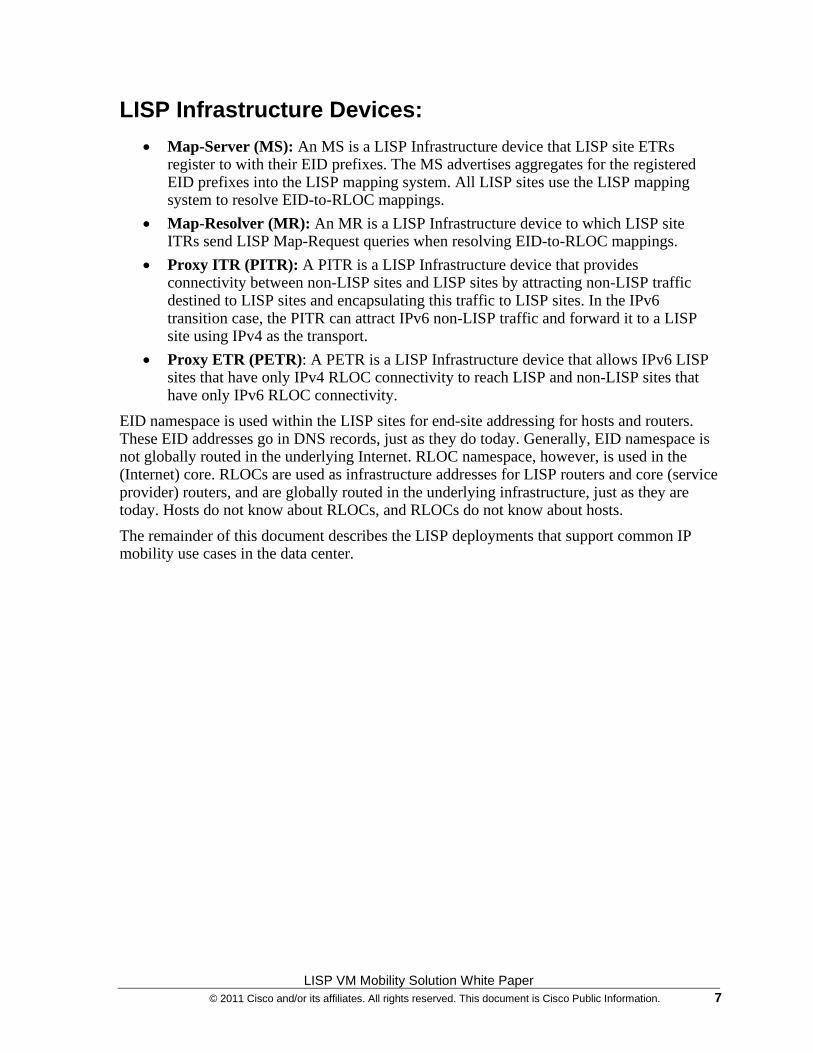
In the LISP VM-Mobility solution, VM migration events are dynamically detected by the LISP Tunnel Router (xTR) based on data plane events. When a move is detected, as illustrated in Figure 2-1, the mappings between EIDs and RLOCs are updated by the new xTR. By updating the RLOC-to-EID mappings, traffic is redirected to the new locations without causing any churn in the underlying routing.
Figure 2-1 A VM move event is dynamically detected by xTRs and the new location is updated in the LISP mapping database.
LISP VM-Mobility detects moves by comparing the source in the IP header of traffic received from a host against a range of prefixes that are allowed to roam. These prefixes are defined as Dynamic-EIDs in the LISP VM-Mobility solution.

LISP VM Mobility Solution White Paper © 2011 Cisco and/or its affiliates. All rights reserved. This document is Cisco Public Information. 9
When deployed at the first hop router, LISP VM-Mobility provides adaptable and comprehensive first hop router functionality to service the IP gateway needs of the roaming devices that relocate.
LISP VM Mobility Solution White Paper 10 © 2011 Cisco and/or its affiliates. All rights reserved. This document is Cisco Public Information.
C H A P T E R 3
LISP VM-Mobility Use Cases
LISP VM-Mobility is instrumental in providing location flexibility to IP end-points within the data center network. By leveraging LISP VM-Mobility, Virtual Machines (VMs) and other end-points can be deployed anywhere in the data center regardless of their IP addresses, and can freely move across racks, rows or even separate data center locations. This level of flexibility is key in supporting the following deployment scenarios/use cases, where IP end-points must preserve their IP addresses to minimize bring-up time:
Use Case Requirements
Geo-Clusters Optimized routing to IP subnets extended with OTV or VPLS
Fast Bring-up of Disaster Recovery Facilities
Relocation of IP end-points across different subnets.
Cloud Bursting Relocation of IP end-points across organizations
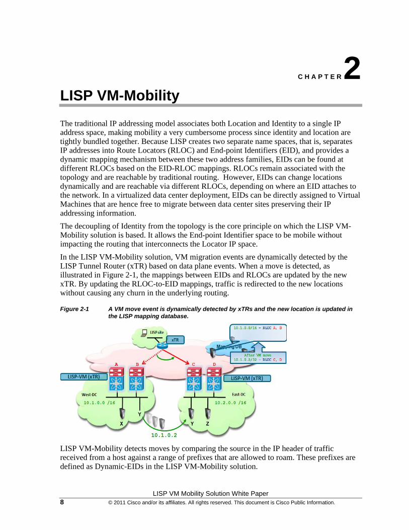
Figure 3-1 shows the LISP VM-Mobility within an extended subnet between two Enterprise class data centers. The Subnets/VLANs are extended from West Data Center to East data Center using either OTV or VPLS, or any other LAN extension technology. In traditional routing, this poses the challenge of ingress path optimization. LISP-VM mobility provides seamless ingress path optimization by detecting the mobile EIDs (Virtual Servers) dynamically, and updates the LISP Mapping system with its current EID-RLOC mapping, which allows the Virtual Servers to be mobile between the data centers with ingress path optimization.
Figure 3-1 LISP VM-Mobility within an Extended Subnet Use Case
LISP VM Mobility Solution White Paper © 2011 Cisco and/or its affiliates. All rights reserved. This document is Cisco Public Information. 11
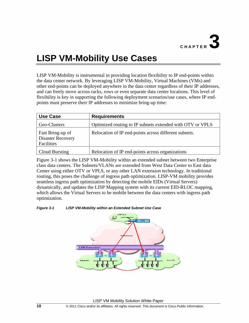
Figure 3-2 shows the LISP VM-Mobility across subnet between two Enterprise class data centers. That is, in this case, two different subnets exist – one in each data center, and subnet/VLAN extension techniques such as OTV or VPLS are not deployed. This mode can be used when the Enterprise IT needs to use Fast Bring-up of Disaster Recovery Facilities in a timely manner, where the network is not provisioned for Virtual Server subnets; or, in case of Cloud Bursting, creating a need for relocation of EIDs across organization boundaries.
Figure 3-2 LISP VM-Mobility Across Subnet
These different deployment scenarios address a variety of business needs, including, but not limited to:
• Improved Application Availability
• Streamlined Disaster Recovery procedures
• Flexible outsourcing options
• Maximized resource utilization
• Flexible change management
This document discusses both of these modes in detail, and provides configuration steps for each of the LISP network elements.
LISP VM-Mobility Prerequisites
• LISP VM-Mobility is supported in general Cisco NX-OS Release 5.2(1) or later. Because of a discovered issue, it is recommended to deploy LISP VM-Mobility solutions leveraging the upcoming NX-OS 5.2(3) release. An engineering build (5.2(1.lisp-r5-20)) containing the fix to the above mentioned issue can be downloaded from http://lisp.cisco.com. The configuration and show outputs contained in this paper have been obtained leveraging this 5.2(1.lisp-r5-20) specific build.
• From an HW perspective, LISP VM-Mobility is currently supported only in N7K-M132XP-12 and in N7K-M132XP-12L linecards. EPLD upgrade to the minimum version 186.008 is required for these linecards.
LISP VM Mobility Solution White Paper 12 © 2011 Cisco and/or its affiliates. All rights reserved. This document is Cisco Public Information.
• LISP VM-Mobility on the Nexus 7000 can leverage F-series modules for site facing interfaces as long as one of the M-series cards mentioned above is available. This is because only M1-32 linecards can perform LISP encapsulation/decapsulation in HW, so it is required for L2 traffic received on F1 interfaces to be internally sent to these M1 cards for that purpose. This functionality available on Nexus 7000 platforms is known as "proxy mode”.
Note: Only the F1 series line cards support proxy mode at the time of writing this document.
• Proxy mode is not supported between M-series cards, so the site facing interfaces can only be N7K-M132XP-12, N7K-M132XP-12L or F-series linecards.
• Traffic received on M-series linecards other than the M132XP-12 cards will not be processed by LISP. Therefore combining M132XP-12 cards with other M-series cards in a LISP enabled VDC will result in two different types of traffic processing depending on which interface receives the traffic. In deployments where other M-series cards (N7K-M148GT-11, N7K-M148GT-11L, N7K-M148GS-11, N7K-M148GS-11L or N7K-M108X2-12L) are part of the same VDC with the F1 and M1-32 cards, it is critical to ensure that traffic received on any F1 interfaces is internally sent only to interfaces belonging to M1-32 cards. The "hardware proxy layer-3 forwarding use interface" command can be leveraged to list only these specific interfaces to be used for proxy-routing purpose.
LISP VM Mobility Solution White Paper © 2011 Cisco and/or its affiliates. All rights reserved. This document is Cisco Public Information. 13
C H A P T E R 4
LISP VM-Mobility Operation
The LISP VM-Mobility functionality allows any IP addressable device (host) to move (or “roam”) from its subnet to a completely different subnet, or to an extension of its subnet in a different location (e.g. in a remote Data Center) – while keeping its original IP address. In LISP terminology, a device that moves is called a “roaming device,” and its IP address is called its “dynamic-EID.” The LISP xTR configured with LISP VM-mobility features with a dynamic-eid clause is called a LISP-VM router. The dynamic-eid clause may represent one or more dynamic-eids. The LISP-VM router (xTR) devices dynamically determine when a dynamic-EID moves on or off one of its directly connected subnets. A LISP-VM router's IP addresses are the locators (RLOCs) used for encapsulation for traffic to and from the dynamic-EID.
Before looking in more detail into the mechanisms allowing a roaming device to move between physical locations, it is important to introduce the concepts of LISP Site, and Data Center Site, and clarify their relationship.
• LISP Site: A logical construct comprising one or more EID prefixes that have a unique locator-set.
• Data Center Site: A physical construct comprising one or more xTRs participating in a LISP Site. o A LISP Site is fully constituted by a single Data Center Site when the EID
prefix(es) and the unique locator set are wholly contained within that single Data Center Site. In this case, a single Data Center Site constitutes (and is equivalent to) an entire LISP Site.
o A LISP Site is fully constituted by two or more Data Center Sites when the EID prefix(es) and the unique locator set are distributed across multiple Data Center Sites. In this case, a single LISP site includes multiple Data Center sites.
• Dynamic-EID: A host (physical or Virtual Machine) participating in VM-Mobility and that is capable of moving among multiple Layer 3 devices. When a dynamic-EID moves, the "moved-from" Layer 3 device and the "moved-to" Layer 3 device can have the exact same network prefix (and match that of the dynamic-EID), or can have different network prefixes. o When the new (“moved-to”) Layer 3 device carries the same network prefix as
that of the dynamic-EID, LISP VM-Mobility will be configured with "extended subnets" commands and functionality. When this is the case, a Layer 2 extension mechanism such as OTV must also be deployed.
o When the new (“moved-to”) Layer 3 device carries a different network prefix as that of the dynamic-EID, LISP VM-Mobility will be configured with "across subnets" commands and functionality. When this is the case, a Layer 2 extension mechanism such as OTV is not required.
LISP VM Mobility Solution White Paper 14 © 2011 Cisco and/or its affiliates. All rights reserved. This document is Cisco Public Information.
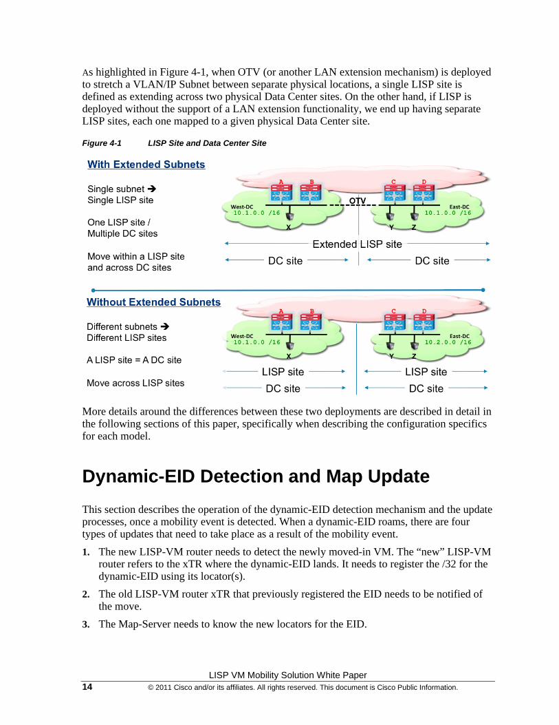
As highlighted in Figure 4-1, when OTV (or another LAN extension mechanism) is deployed to stretch a VLAN/IP Subnet between separate physical locations, a single LISP site is defined as extending across two physical Data Center sites. On the other hand, if LISP is deployed without the support of a LAN extension functionality, we end up having separate LISP sites, each one mapped to a given physical Data Center site.
Figure 4-1 LISP Site and Data Center Site
More details around the differences between these two deployments are described in detail in the following sections of this paper, specifically when describing the configuration specifics for each model.
Dynamic-EID Detection and Map Update
This section describes the operation of the dynamic-EID detection mechanism and the update processes, once a mobility event is detected. When a dynamic-EID roams, there are four types of updates that need to take place as a result of the mobility event.
1. The new LISP-VM router needs to detect the newly moved-in VM. The “new” LISP-VM router refers to the xTR where the dynamic-EID lands. It needs to register the /32 for the dynamic-EID using its locator(s).
2. The old LISP-VM router xTR that previously registered the EID needs to be notified of the move.
3. The Map-Server needs to know the new locators for the EID.

LISP VM Mobility Solution White Paper © 2011 Cisco and/or its affiliates. All rights reserved. This document is Cisco Public Information. 15
4. The remote ITRs and PITRs that have the dynamic-EID cached with old RLOC mapping need to be updated with a new mapping.
The LISP xTR configured as a LISP-VM router detects new dynamic-EID VM move events if:
• It receives a data packet from a source (the newly arrived VM) that is not on the configured subnets for that interface, and
• The source matches the dynamic-EID configuration applied to the interface.
In an Extended Subnet case, the LISP-VM router interfaces are configured with the “lisp extended-subnet-mode” command. In this case, the LISP-VM router detects new VM move events if it receives a data packet from a source that matches the dynamic-EID configured for that interface. This dynamic EID move detection by the LISP-VM router will trigger a Map-Register to the map-server with the database-mapping details from the dynamic-EID-map configuration. It is also worth noticing that in the current implementation, an EID discovered in Extended Subnet mode would remain in the dynamic-EID table of the xTR device (LISP-VM router) until it moves to a separate data center site, independently from the fact that it may have gone silent or even disconnected (obviously in that case the dynamic-EID table could be manually cleared).
In Across Subnet mode instead, the LISP-VM router continues to check for the existence of any previously discovered EID (liveliness check performed by pinging the EID). An EID would hence be removed from the dynamic-EID table only when is disconnected from the network (and not if it just stops sending traffic).
Consider Figure 4-2, below. If EID S1-1.1.1.1 roams to LISP-VM router B, B will detect this move if it receives any data packet from S1, as it is off-subnet traffic. Also, B will register the EID-prefix 1.1.1.1/32 with locator RLOC-B to the configured map-server(s) associated with the configured dynamic-EID. This is required so packets can now be encapsulated to RLOC-B instead of RLOC-A for the host that has moved away.
Figure 4-2 Dynamic-EID Movement
LISP VM Mobility Solution White Paper 16 © 2011 Cisco and/or its affiliates. All rights reserved. This document is Cisco Public Information.
Map-Server and Map-Resolver Consideration
The Map-Server and Map-Resolver are key components in a LISP deployment. They provide capabilities to store and resolve the EID-to-RLOC mapping information for the LISP routers to route between LISP sites.
The Map-Server is a network infrastructure component which learns EID-to-RLOC mapping entries from ETRs that are authoritative sources and that publish (register) their EID-to-RLOC mapping relationships with the Map-Server. A Map-Resolver is a network infrastructure component which accepts LISP encapsulated Map-Requests, typically from an ITR, and finds the appropriate EID-to-RLOC mapping by checking with a collocated Map-Server (typically), or by consulting the distributed mapping system.
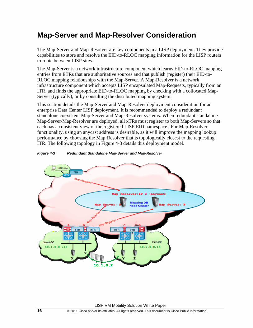
This section details the Map-Server and Map-Resolver deployment consideration for an enterprise Data Center LISP deployment. It is recommended to deploy a redundant standalone coexistent Map-Server and Map-Resolver systems. When redundant standalone Map-Server/Map-Resolver are deployed, all xTRs must register to both Map-Servers so that each has a consistent view of the registered LISP EID namespace. For Map-Resolver functionality, using an anycast address is desirable, as it will improve the mapping lookup performance by choosing the Map-Resolver that is topologically closest to the requesting ITR. The following topology in Figure 4-3 details this deployment model.
Figure 4-3 Redundant Standalone Map-Server and Map-Resolver
LISP VM Mobility Solution White Paper © 2011 Cisco and/or its affiliates. All rights reserved. This document is Cisco Public Information. 17
This document focuses only on a single standalone collocated Map-Server and Map-Resolver.
Note: In the scenarios explored in this document, we will focus on having both the Map Server as well as the Map Resolver functionality collocated in the same network device. We will also focus on a simple use case that does not require a distributed Mapping database. Redundancy of the mapping database will be discussed and is not to be confused with the distribution of the mapping database.
Note: For large scale LISP deployments, the Mapping database can be distributed and MS/MR functionality dispersed onto different nodes. The distribution of the mapping database can be achieved in many different ways, LISP-ALT is one example, but there are many proposals that may be used. Large scale LISP deployments using distributed mapping databases are not discussed in this document.
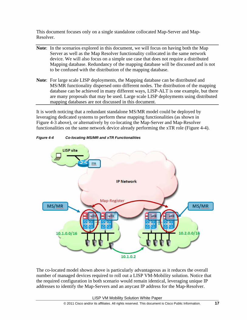
It is worth noticing that a redundant standalone MS/MR model could be deployed by leveraging dedicated systems to perform these mapping functionalities (as shown in Figure 4-3 above), or alternatively by co-locating the Map-Server and Map-Resolver functionalities on the same network device already performing the xTR role (Figure 4-4).
Figure 4-4 Co-locating MS/MR and xTR Functionalities
The co-located model shown above is particularly advantageous as it reduces the overall number of managed devices required to roll out a LISP VM-Mobility solution. Notice that the required configuration in both scenario would remain identical, leveraging unique IP addresses to identify the Map-Servers and an anycast IP address for the Map-Resolver.
LISP VM Mobility Solution White Paper 18 © 2011 Cisco and/or its affiliates. All rights reserved. This document is Cisco Public Information.
C H A P T E R 5
Deploying LISP VM-Mobility within an Extended Subnet
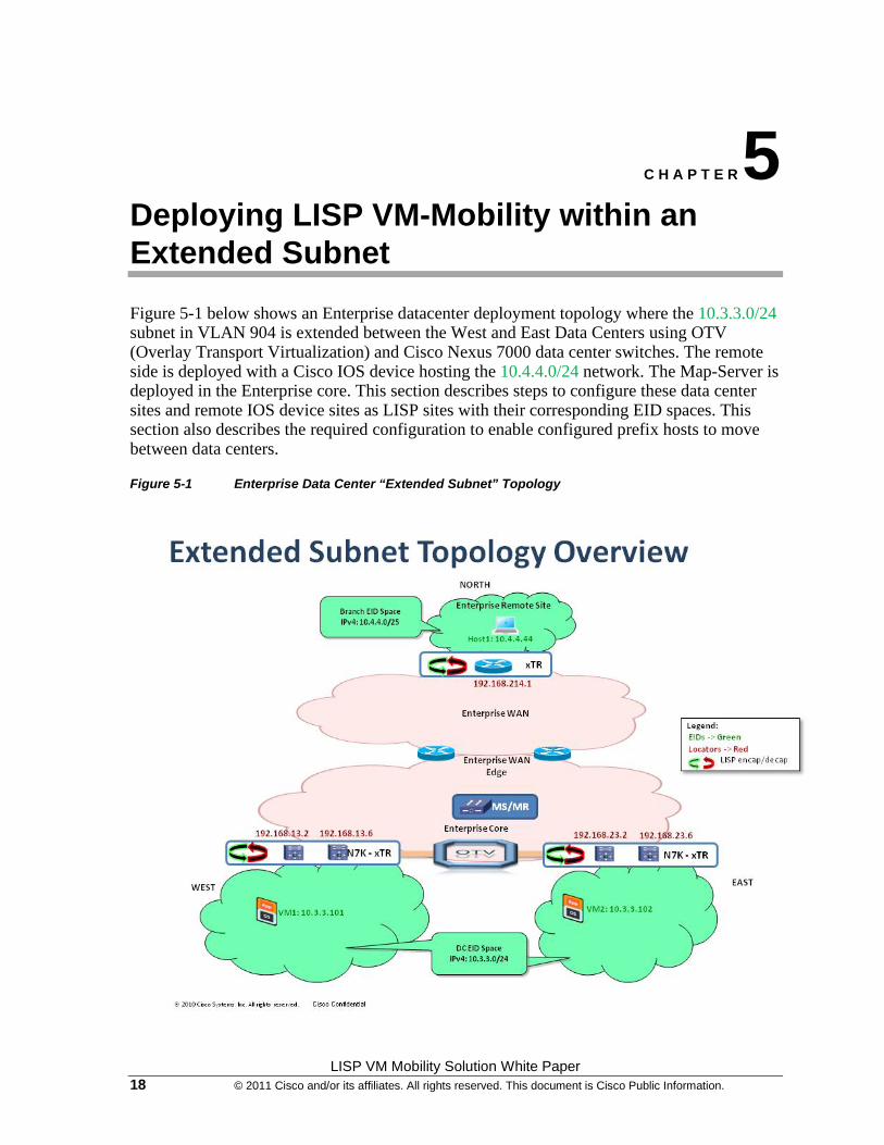
Figure 5-1 below shows an Enterprise datacenter deployment topology where the 10.3.3.0/24 subnet in VLAN 904 is extended between the West and East Data Centers using OTV (Overlay Transport Virtualization) and Cisco Nexus 7000 data center switches. The remote side is deployed with a Cisco IOS device hosting the 10.4.4.0/24 network. The Map-Server is deployed in the Enterprise core. This section describes steps to configure these data center sites and remote IOS device sites as LISP sites with their corresponding EID spaces. This section also describes the required configuration to enable configured prefix hosts to move between data centers.
Figure 5-1 Enterprise Data Center “Extended Subnet” Topology

LISP VM Mobility Solution White Paper © 2011 Cisco and/or its affiliates. All rights reserved. This document is Cisco Public Information. 19
LISP VM-Mobility within an Extended Subnet Prerequisites
• OTV or any other deployed LAN extension solution should filter the HSRP hello messages across the data centers, creating an active-active HSRP setup. This is mainly done to provide an active default gateway in each physical Data Center location and avoid asymmetric traffic handling when optimizing ingress traffic with LISP (HSRP localization handles only the egress flows). For more details on how to achieve HSRP localization when deploying OTV, please refer to paper below:
• http://www.cisco.com/en/US/solutions/collateral/ns340/ns517/ns224/ns949/ns304/ns975/OTV_intro_wp.pdf
• The default gateway Virtual MAC and IP addresses in both data centers should remain consistent, as the mobile VM would continue to send packets to the same GW IP address. Virtual MAC consistency is achieved by configuring the same HSRP group associated to the same subnet in separate Data Center sites.
• OTV or any other deployed LAN extension solution should have multicast support over the extended L2 circuit in order for the proper operation of the LISP VM-Mobility in an extended subnet mode.
Configuring a Cisco Nexus 7000 Switch as a LISP xTR
Enter the commands shown below to enable and configure LISP ITR/ETR (xTR) functionality on a Nexus 7000 switch.
Configuration Steps 1. configure terminal
2. feature lisp
3. ip lisp itr-etr
4. ip lisp database‐mapping EID‐prefix/prefix‐length locator_ip priority priority weight weight
5. ip lisp etr map‐server map‐server‐address key key‐type authentication‐key
6. ip lisp itr map-resolver <map-resolver-address>
7. exit
LISP VM Mobility Solution White Paper 20 © 2011 Cisco and/or its affiliates. All rights reserved. This document is Cisco Public Information.
Steps NX-OS Commands Purpose
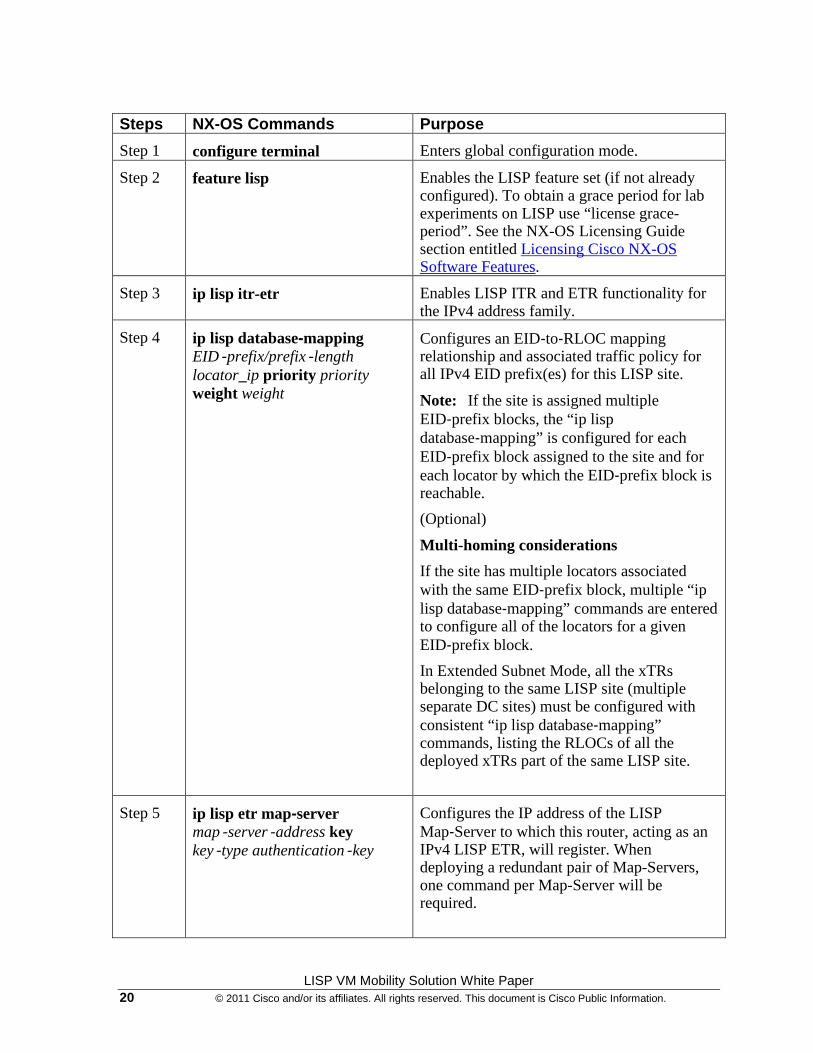
Step 1 configure terminal Enters global configuration mode.
Step 2 feature lisp Enables the LISP feature set (if not already configured). To obtain a grace period for lab experiments on LISP use “license grace-period”. See the NX-OS Licensing Guide section entitled Licensing Cisco NX-OS Software Features.
Step 3 ip lisp itr-etr Enables LISP ITR and ETR functionality for the IPv4 address family.
Step 4 ip lisp database-mapping EID‐prefix/prefix‐length locator_ip priority priority weight weight
Configures an EID‐to‐RLOC mapping relationship and associated traffic policy for all IPv4 EID prefix(es) for this LISP site.
Note: If the site is assigned multiple EID‐prefix blocks, the “ip lisp database‐mapping” is configured for each EID‐prefix block assigned to the site and for each locator by which the EID‐prefix block is reachable.
(Optional)
Multi-homing considerations
If the site has multiple locators associated with the same EID‐prefix block, multiple “ip lisp database‐mapping” commands are entered to configure all of the locators for a given EID‐prefix block.
In Extended Subnet Mode, all the xTRs belonging to the same LISP site (multiple separate DC sites) must be configured with consistent “ip lisp database‐mapping” commands, listing the RLOCs of all the deployed xTRs part of the same LISP site.
Step 5 ip lisp etr map-server map‐server‐address key key‐type authentication‐key
Configures the IP address of the LISP Map‐Server to which this router, acting as an IPv4 LISP ETR, will register. When deploying a redundant pair of Map-Servers, one command per Map-Server will be required.
LISP VM Mobility Solution White Paper © 2011 Cisco and/or its affiliates. All rights reserved. This document is Cisco Public Information. 21
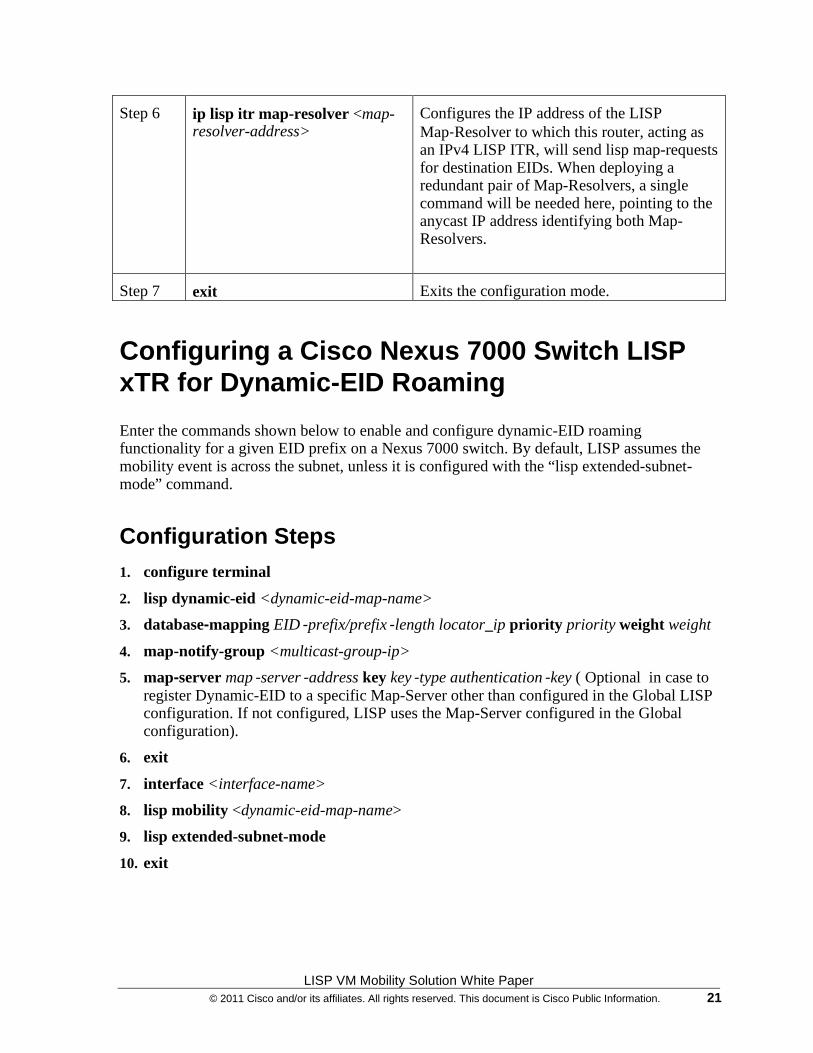
Step 6 ip lisp itr map-resolver <map-resolver-address>
Configures the IP address of the LISP Map‐Resolver to which this router, acting as an IPv4 LISP ITR, will send lisp map-requests for destination EIDs. When deploying a redundant pair of Map-Resolvers, a single command will be needed here, pointing to the anycast IP address identifying both Map-Resolvers.
Step 7 exit Exits the configuration mode.
Configuring a Cisco Nexus 7000 Switch LISP xTR for Dynamic-EID Roaming
Enter the commands shown below to enable and configure dynamic-EID roaming functionality for a given EID prefix on a Nexus 7000 switch. By default, LISP assumes the mobility event is across the subnet, unless it is configured with the “lisp extended-subnet-mode” command.
Configuration Steps 1. configure terminal
2. lisp dynamic-eid <dynamic-eid-map-name>
3. database-mapping EID‐prefix/prefix‐length locator_ip priority priority weight weight
4. map-notify-group <multicast-group-ip>
5. map-server map‐server‐address key key‐type authentication‐key ( Optional in case to register Dynamic-EID to a specific Map-Server other than configured in the Global LISP configuration. If not configured, LISP uses the Map-Server configured in the Global configuration).
6. exit
7. interface <interface-name>
8. lisp mobility <dynamic-eid-map-name>
9. lisp extended-subnet-mode
10. exit
LISP VM Mobility Solution White Paper 22 © 2011 Cisco and/or its affiliates. All rights reserved. This document is Cisco Public Information.
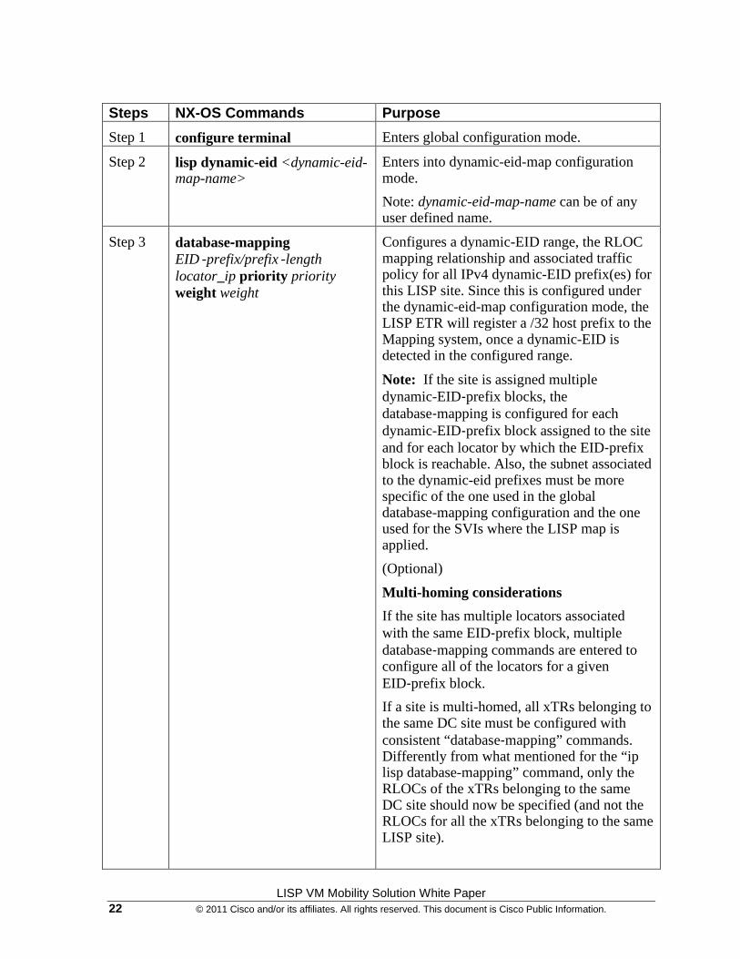
Steps NX-OS Commands Purpose
Step 1 configure terminal Enters global configuration mode.
Step 2 lisp dynamic-eid <dynamic-eid-map-name>
Enters into dynamic-eid-map configuration mode.
Note: dynamic-eid-map-name can be of any user defined name.
Step 3 database-mapping EID‐prefix/prefix‐length locator_ip priority priority weight weight
Configures a dynamic-EID range, the RLOC mapping relationship and associated traffic policy for all IPv4 dynamic-EID prefix(es) for this LISP site. Since this is configured under the dynamic-eid-map configuration mode, the LISP ETR will register a /32 host prefix to the Mapping system, once a dynamic-EID is detected in the configured range.
Note: If the site is assigned multiple dynamic-EID‐prefix blocks, the database‐mapping is configured for each dynamic-EID‐prefix block assigned to the site and for each locator by which the EID‐prefix block is reachable. Also, the subnet associated to the dynamic-eid prefixes must be more specific of the one used in the global database-mapping configuration and the one used for the SVIs where the LISP map is applied.
(Optional)
Multi-homing considerations
If the site has multiple locators associated with the same EID‐prefix block, multiple database‐mapping commands are entered to configure all of the locators for a given EID‐prefix block.
If a site is multi-homed, all xTRs belonging to the same DC site must be configured with consistent “database‐mapping” commands. Differently from what mentioned for the “ip lisp database-mapping” command, only the RLOCs of the xTRs belonging to the same DC site should now be specified (and not the RLOCs for all the xTRs belonging to the same LISP site).
LISP VM Mobility Solution White Paper © 2011 Cisco and/or its affiliates. All rights reserved. This document is Cisco Public Information. 23
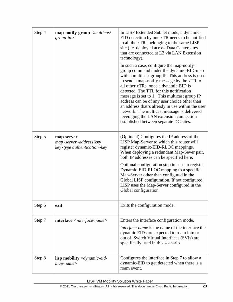
Step 4 map-notify-group <multicast-group-ip>
In LISP Extended Subnet mode, a dynamic-EID detection by one xTR needs to be notified to all the xTRs belonging to the same LISP site (i.e. deployed across Data Center sites that are connected at L2 via LAN Extension technology).
In such a case, configure the map-notify-group command under the dynamic-EID-map with a multicast group IP. This address is used to send a map-notify message by the xTR to all other xTRs, once a dynamic-EID is detected. The TTL for this notification message is set to 1. This multicast group IP address can be of any user choice other than an address that’s already in use within the user network. The multicast message is delivered leveraging the LAN extension connection established between separate DC sites.
Step 5 map-server map‐server‐address key key‐type authentication‐key
(Optional) Configures the IP address of the LISP Map‐Server to which this router will register dynamic-EID-RLOC mappings. When deploying a redundant Map-Sever pair, both IP addresses can be specified here.
Optional configuration step in case to register Dynamic-EID-RLOC mapping to a specific Map-Server other than configured in the Global LISP configuration. If not configured, LISP uses the Map-Server configured in the Global configuration.
Step 6 exit Exits the configuration mode.
Step 7 interface <interface-name>
Enters the interface configuration mode.
interface-name is the name of the interface the dynamic EIDs are expected to roam into or out of. Switch Virtual Interfaces (SVIs) are specifically used in this scenario.
Step 8 lisp mobility <dynamic-eid-map-name>
Configures the interface in Step 7 to allow a dynamic-EID to get detected when there is a roam event.
LISP VM Mobility Solution White Paper 24 © 2011 Cisco and/or its affiliates. All rights reserved. This document is Cisco Public Information.
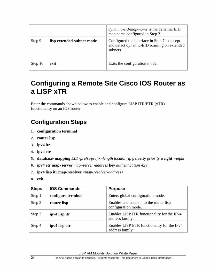
dynamic-eid-map-name is the dynamic EID map name configured in Step 2.
Step 9 lisp extended-subnet-mode
Configured the interface in Step 7 to accept and detect dynamic-EID roaming on extended subnets.
Step 10 exit Exits the configuration mode.
Configuring a Remote Site Cisco IOS Router as a LISP xTR
Enter the commands shown below to enable and configure LISP ITR/ETR (xTR) functionality on an IOS router.
Configuration Steps 1. configuration terminal
2. router lisp
3. ipv4 itr
4. ipv4 etr
5. database‐mapping EID‐prefix/prefix‐length locator_ip priority priority weight weight
6. ipv4 etr map‐server map‐server‐address key authentication‐key
7. ipv4 lisp itr map-resolver <map-resolver-address>
8. exit Steps IOS Commands Purpose
Step 1 configure terminal Enters global configuration mode.
Step 2 router lisp Enables and enters into the router lisp configuration mode.
Step 3 ipv4 lisp itr Enables LISP ITR functionality for the IPv4 address family.
Step 4 ipv4 lisp etr Enables LISP ETR functionality for the IPv4 address family.
LISP VM Mobility Solution White Paper © 2011 Cisco and/or its affiliates. All rights reserved. This document is Cisco Public Information. 25
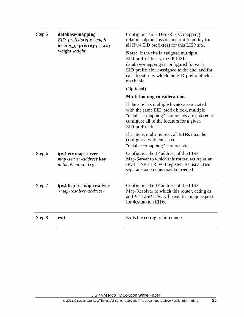
Step 5 database-mapping EID‐prefix/prefix‐length locator_ip priority priority weight weight
Configures an EID‐to‐RLOC mapping relationship and associated traffic policy for all IPv4 EID prefix(es) for this LISP site.
Note: If the site is assigned multiple EID‐prefix blocks, the IP LISP database‐mapping is configured for each EID‐prefix block assigned to the site, and for each locator by which the EID‐prefix block is reachable.
(Optional)
Multi-homing considerations
If the site has multiple locators associated with the same EID‐prefix block, multiple “database‐mapping” commands are entered to configure all of the locators for a given EID‐prefix block.
If a site is multi-homed, all ETRs must be configured with consistent “database‐mapping” commands.
Step 6 ipv4 etr map-server map‐server‐address key authentication‐key
Configures the IP address of the LISP Map‐Server to which this router, acting as an IPv4 LISP ETR, will register. As usual, two separate statements may be needed.
Step 7 ipv4 lisp itr map-resolver <map-resolver-address>
Configures the IP address of the LISP Map‐Resolver to which this router, acting as an IPv4 LISP ITR, will send lisp map-request for destination EIDs.
Step 8 exit Exits the configuration mode.
LISP VM Mobility Solution White Paper 26 © 2011 Cisco and/or its affiliates. All rights reserved. This document is Cisco Public Information.
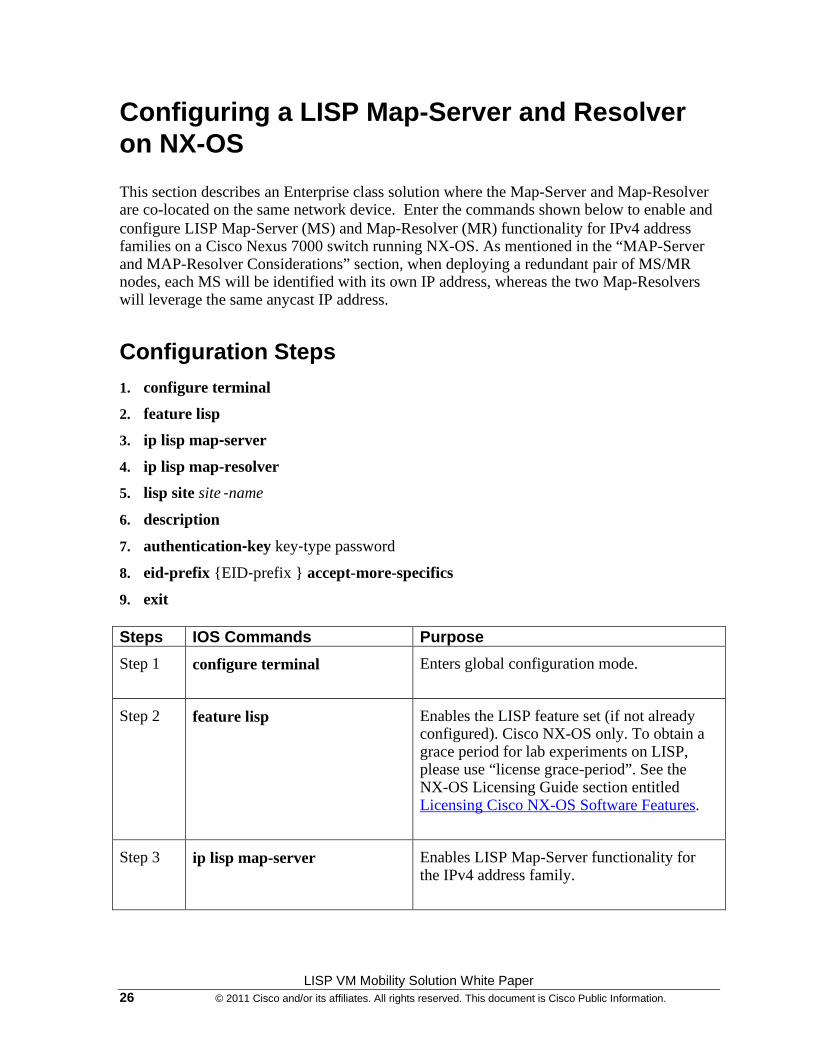
Configuring a LISP Map-Server and Resolver on NX-OS
This section describes an Enterprise class solution where the Map-Server and Map-Resolver are co-located on the same network device. Enter the commands shown below to enable and configure LISP Map‐Server (MS) and Map-Resolver (MR) functionality for IPv4 address families on a Cisco Nexus 7000 switch running NX-OS. As mentioned in the “MAP-Server and MAP-Resolver Considerations” section, when deploying a redundant pair of MS/MR nodes, each MS will be identified with its own IP address, whereas the two Map-Resolvers will leverage the same anycast IP address.
Configuration Steps 1. configure terminal
2. feature lisp
3. ip lisp map-server
4. ip lisp map-resolver
5. lisp site site‐name
6. description
7. authentication-key key‐type password
8. eid-prefix {EID‐prefix } accept-more-specifics
9. exit Steps IOS Commands Purpose
Step 1 configure terminal Enters global configuration mode.
Step 2 feature lisp Enables the LISP feature set (if not already configured). Cisco NX-OS only. To obtain a grace period for lab experiments on LISP, please use “license grace-period”. See the NX-OS Licensing Guide section entitled Licensing Cisco NX-OS Software Features.
Step 3 ip lisp map-server Enables LISP Map-Server functionality for the IPv4 address family.

LISP VM Mobility Solution White Paper © 2011 Cisco and/or its affiliates. All rights reserved. This document is Cisco Public Information. 27
Step 4 ip lisp map-resolver Enables LISP Map Resolver functionality for the IPv4 address family.
Step 5 lisp site site‐name
Creates the indicated LISP site and enters LISP site configuration mode.
Step 6 description description
Enters a description for the LISP site being configured.
Step 7 authentication-key key‐type password
Enters the authentication key type and password for the LISP site being configured.
Note: The password must match the one configured on the ETRs in order for the ETRs to successfully register.
Step 8 eid-prefix {EID‐prefix } accept-more-specifics
Enters the EID‐prefix for which the LISP site being configured is authoritative, and configures to accept more specific prefixes in case of dynamic-eid-map configurations in the ETR.
Note: If the ETR is configured with a dynamic-eid-map with a prefix to roam, that prefix should be configured in the Map-Server with this command.
Step 9 exit Exits the configuration mode.
LISP VM Mobility Solution White Paper 28 © 2011 Cisco and/or its affiliates. All rights reserved. This document is Cisco Public Information.
LISP VM-Mobility within an Extended Subnet: Configuration Example
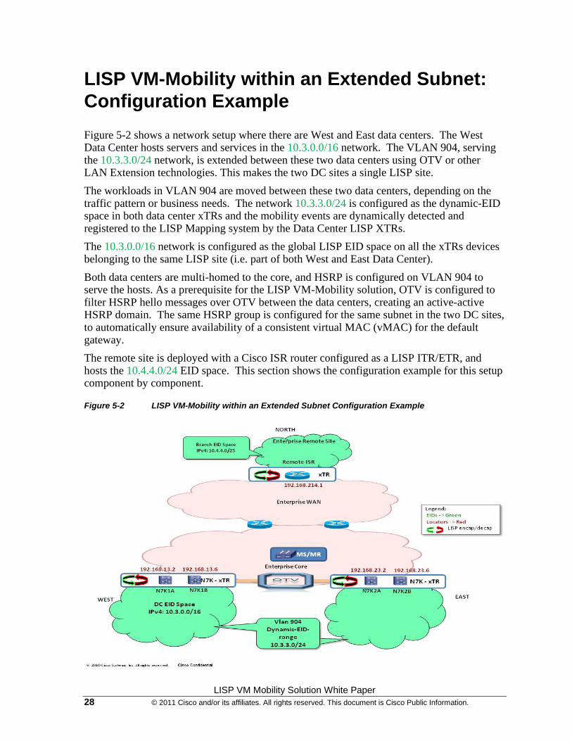
Figure 5-2 shows a network setup where there are West and East data centers. The West Data Center hosts servers and services in the 10.3.0.0/16 network. The VLAN 904, serving the 10.3.3.0/24 network, is extended between these two data centers using OTV or other LAN Extension technologies. This makes the two DC sites a single LISP site.
The workloads in VLAN 904 are moved between these two data centers, depending on the traffic pattern or business needs. The network 10.3.3.0/24 is configured as the dynamic-EID space in both data center xTRs and the mobility events are dynamically detected and registered to the LISP Mapping system by the Data Center LISP XTRs.
The 10.3.0.0/16 network is configured as the global LISP EID space on all the xTRs devices belonging to the same LISP site (i.e. part of both West and East Data Center).
Both data centers are multi-homed to the core, and HSRP is configured on VLAN 904 to serve the hosts. As a prerequisite for the LISP VM-Mobility solution, OTV is configured to filter HSRP hello messages over OTV between the data centers, creating an active-active HSRP domain. The same HSRP group is configured for the same subnet in the two DC sites, to automatically ensure availability of a consistent virtual MAC (vMAC) for the default gateway.
The remote site is deployed with a Cisco ISR router configured as a LISP ITR/ETR, and hosts the 10.4.4.0/24 EID space. This section shows the configuration example for this setup component by component.
Figure 5-2 LISP VM-Mobility within an Extended Subnet Configuration Example
LISP VM Mobility Solution White Paper © 2011 Cisco and/or its affiliates. All rights reserved. This document is Cisco Public Information. 29
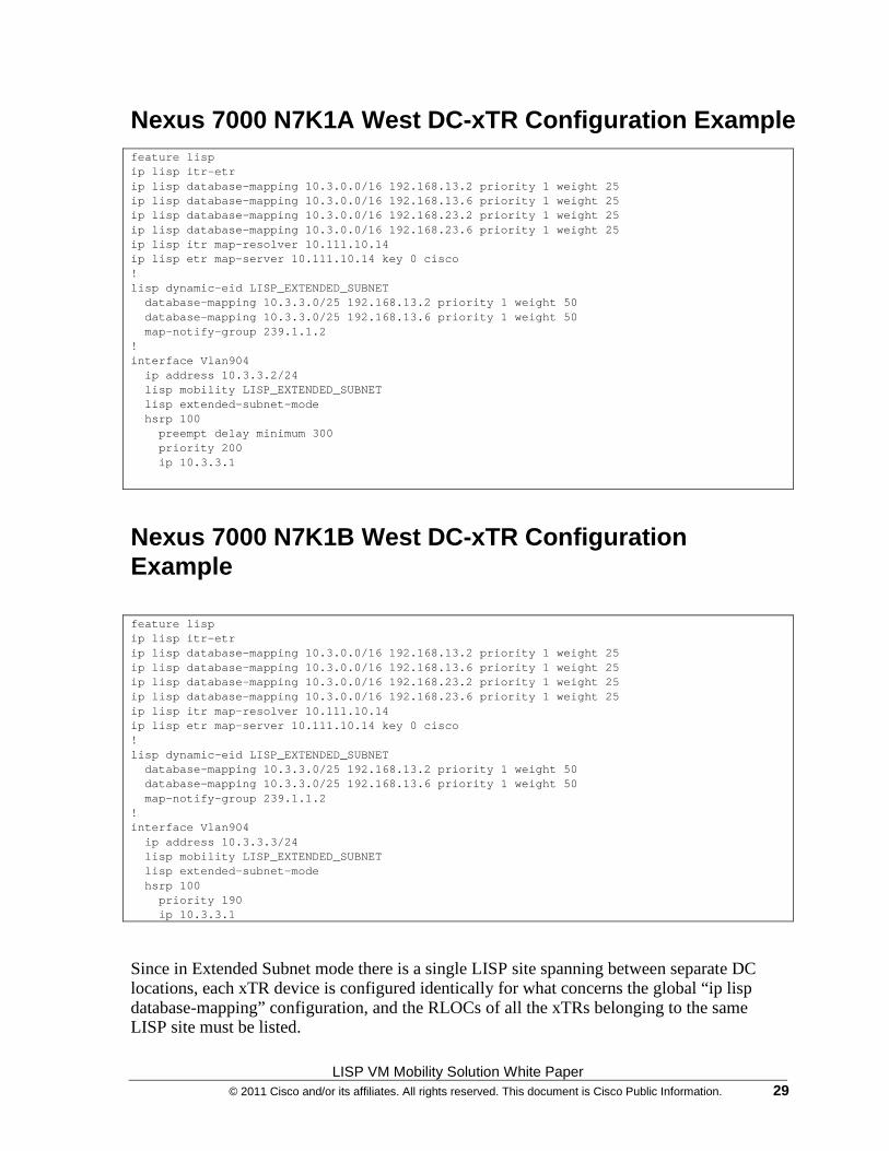
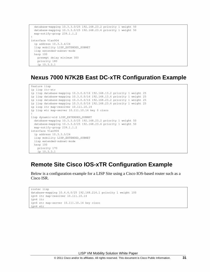
Nexus 7000 N7K1A West DC-xTR Configuration Example feature lisp ip lisp itr-etr ip lisp database-mapping 10.3.0.0/16 192.168.13.2 priority 1 weight 25 ip lisp database-mapping 10.3.0.0/16 192.168.13.6 priority 1 weight 25 ip lisp database-mapping 10.3.0.0/16 192.168.23.2 priority 1 weight 25 ip lisp database-mapping 10.3.0.0/16 192.168.23.6 priority 1 weight 25 ip lisp itr map-resolver 10.111.10.14 ip lisp etr map-server 10.111.10.14 key 0 cisco ! lisp dynamic-eid LISP_EXTENDED_SUBNET database-mapping 10.3.3.0/25 192.168.13.2 priority 1 weight 50 database-mapping 10.3.3.0/25 192.168.13.6 priority 1 weight 50 map-notify-group 239.1.1.2 ! interface Vlan904 ip address 10.3.3.2/24 lisp mobility LISP_EXTENDED_SUBNET lisp extended-subnet-mode hsrp 100 preempt delay minimum 300 priority 200 ip 10.3.3.1
Nexus 7000 N7K1B West DC-xTR Configuration Example feature lisp ip lisp itr-etr ip lisp database-mapping 10.3.0.0/16 192.168.13.2 priority 1 weight 25 ip lisp database-mapping 10.3.0.0/16 192.168.13.6 priority 1 weight 25 ip lisp database-mapping 10.3.0.0/16 192.168.23.2 priority 1 weight 25 ip lisp database-mapping 10.3.0.0/16 192.168.23.6 priority 1 weight 25 ip lisp itr map-resolver 10.111.10.14 ip lisp etr map-server 10.111.10.14 key 0 cisco ! lisp dynamic-eid LISP_EXTENDED_SUBNET database-mapping 10.3.3.0/25 192.168.13.2 priority 1 weight 50 database-mapping 10.3.3.0/25 192.168.13.6 priority 1 weight 50 map-notify-group 239.1.1.2 ! interface Vlan904 ip address 10.3.3.3/24 lisp mobility LISP_EXTENDED_SUBNET lisp extended-subnet-mode hsrp 100 priority 190 ip 10.3.3.1
Since in Extended Subnet mode there is a single LISP site spanning between separate DC locations, each xTR device is configured identically for what concerns the global “ip lisp database-mapping” configuration, and the RLOCs of all the xTRs belonging to the same LISP site must be listed.
LISP VM Mobility Solution White Paper 30 © 2011 Cisco and/or its affiliates. All rights reserved. This document is Cisco Public Information.
This is not true for the “dynamic-eid” portion of the configuration, where only the RLOCs of the xTRs belonging to the same physical DC site must be listed. Notice also that in the example above the same priority and weight was configured for each defined RLOC (default behavior). If desired, it is possible to modify these parameters when the goal is not to load-balance incoming LISP from other xTRs.
Important: it is critical to ensure that the prefixes specified under the dynamic-EID portion of the configuration are more specific (from a subnet mask point of view) of the ones configured as part of the global “ip lisp database-mapping” section. Also, the dynamic-eid prefixes need to be more specific of the subnet mask configured on the L3 interface where the dynamic-eid map is applied (SVI 904 in the example above). In the example above, /16 was the mask associated to the prefix in the global mapping, /24 was used as mask for the IP subnet associated to the SVI, whereas /25 was used as part of the dynamic-eid mapping.
Also, note that the map-notification between multi-homed xTRs are done through multicast address. In extended subnet mode case, the multicast support over the LAN extension (OTV or any other DCI) is required for proper operation. In order for this to be possible, it is required to use the same multicast address (for each defined dynamic-eid prefix) across all the xTR devices belonging to the same LISP site (239.1.1.2 in the example above is hence deployed on the xTRs belonging to DC sites 1 and 2).
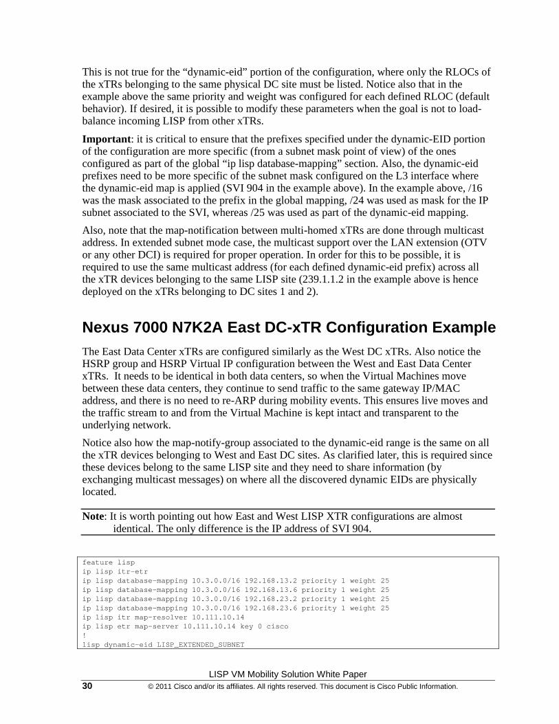
Nexus 7000 N7K2A East DC-xTR Configuration Example The East Data Center xTRs are configured similarly as the West DC xTRs. Also notice the HSRP group and HSRP Virtual IP configuration between the West and East Data Center xTRs. It needs to be identical in both data centers, so when the Virtual Machines move between these data centers, they continue to send traffic to the same gateway IP/MAC address, and there is no need to re-ARP during mobility events. This ensures live moves and the traffic stream to and from the Virtual Machine is kept intact and transparent to the underlying network.
Notice also how the map-notify-group associated to the dynamic-eid range is the same on all the xTR devices belonging to West and East DC sites. As clarified later, this is required since these devices belong to the same LISP site and they need to share information (by exchanging multicast messages) on where all the discovered dynamic EIDs are physically located.
Note: It is worth pointing out how East and West LISP XTR configurations are almost identical. The only difference is the IP address of SVI 904.
feature lisp ip lisp itr-etr ip lisp database-mapping 10.3.0.0/16 192.168.13.2 priority 1 weight 25 ip lisp database-mapping 10.3.0.0/16 192.168.13.6 priority 1 weight 25 ip lisp database-mapping 10.3.0.0/16 192.168.23.2 priority 1 weight 25 ip lisp database-mapping 10.3.0.0/16 192.168.23.6 priority 1 weight 25 ip lisp itr map-resolver 10.111.10.14 ip lisp etr map-server 10.111.10.14 key 0 cisco ! lisp dynamic-eid LISP_EXTENDED_SUBNET
LISP VM Mobility Solution White Paper © 2011 Cisco and/or its affiliates. All rights reserved. This document is Cisco Public Information. 31
database-mapping 10.3.3.0/25 192.168.23.2 priority 1 weight 50 database-mapping 10.3.3.0/25 192.168.23.6 priority 1 weight 50 map-notify-group 239.1.1.2 ! interface Vlan904 ip address 10.3.3.4/24 lisp mobility LISP_EXTENDED_SUBNET lisp extended-subnet-mode hsrp 100 preempt delay minimum 300 priority 180 ip 10.3.3.1
Nexus 7000 N7K2B East DC-xTR Configuration Example feature lisp ip lisp itr-etr ip lisp database-mapping 10.3.0.0/16 192.168.13.2 priority 1 weight 25 ip lisp database-mapping 10.3.0.0/16 192.168.13.6 priority 1 weight 25 ip lisp database-mapping 10.3.0.0/16 192.168.23.2 priority 1 weight 25 ip lisp database-mapping 10.3.0.0/16 192.168.23.6 priority 1 weight 25 ip lisp itr map-resolver 10.111.10.14 ip lisp etr map-server 10.111.10.14 key 0 cisco ! lisp dynamic-eid LISP_EXTENDED_SUBNET database-mapping 10.3.3.0/25 192.168.23.2 priority 1 weight 50 database-mapping 10.3.3.0/25 192.168.23.6 priority 1 weight 50 map-notify-group 239.1.1.2 interface Vlan904 ip address 10.3.3.5/24 lisp mobility LISP_EXTENDED_SUBNET lisp extended-subnet-mode hsrp 100 priority 170 ip 10.3.3.1
Remote Site Cisco IOS-xTR Configuration Example Below is a configuration example for a LISP Site using a Cisco IOS-based router such as a Cisco ISR.
router lisp database-mapping 10.4.4.0/25 192.168.214.1 priority 1 weight 100 ipv4 itr map-resolver 10.111.10.14 ipv4 itr ipv4 etr map-server 10.111.10.14 key cisco ipv4 etr
LISP VM Mobility Solution White Paper 32 © 2011 Cisco and/or its affiliates. All rights reserved. This document is Cisco Public Information.
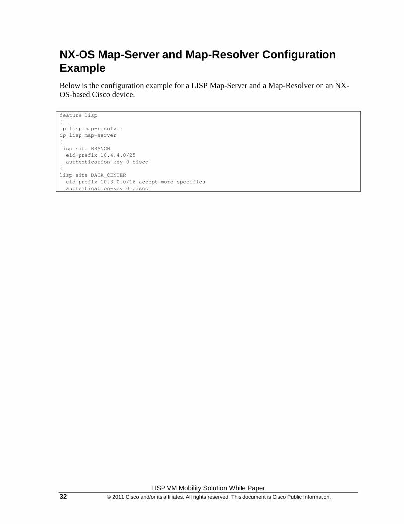
NX-OS Map-Server and Map-Resolver Configuration Example Below is the configuration example for a LISP Map-Server and a Map-Resolver on an NX-OS-based Cisco device.
feature lisp ! ip lisp map-resolver ip lisp map-server ! lisp site BRANCH eid-prefix 10.4.4.0/25 authentication-key 0 cisco ! lisp site DATA_CENTER eid-prefix 10.3.0.0/16 accept-more-specifics authentication-key 0 cisco
LISP VM Mobility Solution White Paper © 2011 Cisco and/or its affiliates. All rights reserved. This document is Cisco Public Information. 33
LISP VM-Mobility within an Extended Subnet Verification Steps
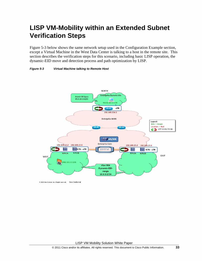
Figure 5-3 below shows the same network setup used in the Configuration Example section, except a Virtual Machine in the West Data Center is talking to a host in the remote site. This section describes the verification steps for this scenario, including basic LISP operation, the dynamic-EID move and detection process and path optimization by LISP.
Figure 5-3 Virtual Machine talking to Remote Host
LISP VM Mobility Solution White Paper 34 © 2011 Cisco and/or its affiliates. All rights reserved. This document is Cisco Public Information.
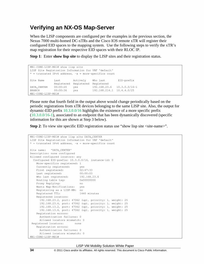
Verifying an NX-OS Map-Server When the LISP components are configured per the examples in the previous section, the Nexus 7000 multi-homed DC-xTRs and the Cisco IOS remote xTR will register their configured EID spaces to the mapping system. Use the following steps to verify the xTR’s map registration for their respective EID spaces with their RLOC IP.
Step 1: Enter show lisp site to display the LISP sites and their registration status.
MB1-CORE-LISP-MS1# show lisp site LISP Site Registration Information for VRF "default" * = truncated IPv6 address, -x = more-specifics count Site Name Last Actively Who last EID-prefix Registered Registered Registered DATA_CENTER 00:00:20 yes 192.168.23.6 10.3.0.0/16-1 BRANCH 00:00:36 yes 192.168.214.1 10.4.4.0/25 MB1-CORE-LISP-MS1#
Please note that fourth field in the output above would change periodically based on the periodic registrations from xTR devices belonging to the same LISP site. Also, the output for dynamic-EID prefix 10.3.0.0/16 highlights the existence of a more specific prefix (10.3.0.0/16-1), associated to an endpoint that has been dynamically discovered (specific information for this are shown at Step 3 below).
Step 2: To view site specific EID registration status use “show lisp site <site-name>”.
MB1-CORE-LISP-MS1# show lisp site DATA_CENTER LISP Site Registration Information for VRF "default" * = truncated IPv6 address, -x = more-specifics count Site name: "DATA_CENTER" Description: none configured Allowed configured locators: any Configured EID-prefix: 10.3.0.0/16, instance-id: 0 More-specifics registered: 1 Currently registered: yes First registered: 02:47:33 Last registered: 00:00:03 Who last registered: 192.168.23.6 Routing table tag: 0x00000000 Proxy Replying: no Wants Map-Notifications: yes Registering as a LISP-MN: no Registered TTL: 1440 minutes Registered locators: 192.168.23.2, port: 47062 (up), priority: 1, weight: 25 192.168.23.6, port: 47062 (up), priority: 1, weight: 25 192.168.13.2, port: 47062 (up), priority: 1, weight: 25 192.168.13.6, port: 47062 (up), priority: 1, weight: 25 Registration errors: Authentication failures: 0 Allowed locators mismatch: 0 Registered locators: none Registration errors: Authentication failures: 0 Allowed locators mismatch: 0 MB1-CORE-LISP-MS1#
LISP VM Mobility Solution White Paper © 2011 Cisco and/or its affiliates. All rights reserved. This document is Cisco Public Information. 35
Note in the above example, since DC-xTRs in West and East DCs are part of the same LISP site, they will register all RLOC IP addresses for their EID spaces.
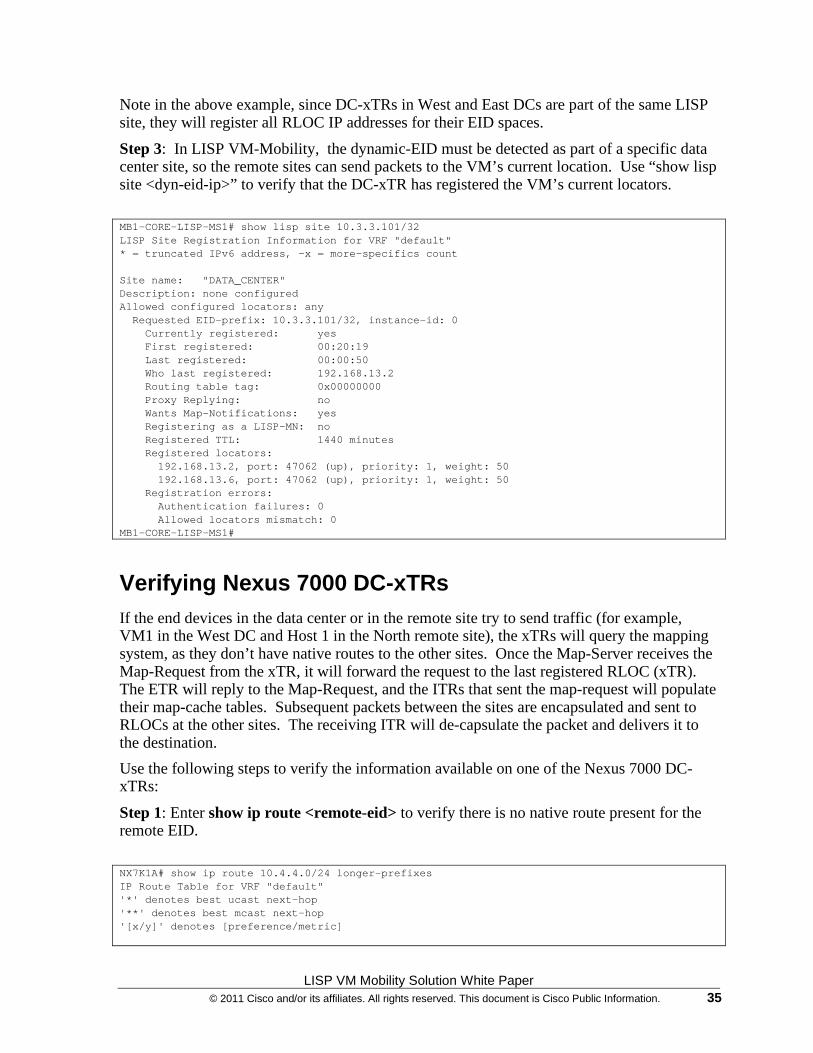
Step 3: In LISP VM-Mobility, the dynamic-EID must be detected as part of a specific data center site, so the remote sites can send packets to the VM’s current location. Use “show lisp site <dyn-eid-ip>” to verify that the DC-xTR has registered the VM’s current locators.
MB1-CORE-LISP-MS1# show lisp site 10.3.3.101/32 LISP Site Registration Information for VRF "default" * = truncated IPv6 address, -x = more-specifics count Site name: "DATA_CENTER" Description: none configured Allowed configured locators: any Requested EID-prefix: 10.3.3.101/32, instance-id: 0 Currently registered: yes First registered: 00:20:19 Last registered: 00:00:50 Who last registered: 192.168.13.2 Routing table tag: 0x00000000 Proxy Replying: no Wants Map-Notifications: yes Registering as a LISP-MN: no Registered TTL: 1440 minutes Registered locators: 192.168.13.2, port: 47062 (up), priority: 1, weight: 50 192.168.13.6, port: 47062 (up), priority: 1, weight: 50 Registration errors: Authentication failures: 0 Allowed locators mismatch: 0 MB1-CORE-LISP-MS1#
Verifying Nexus 7000 DC-xTRs If the end devices in the data center or in the remote site try to send traffic (for example, VM1 in the West DC and Host 1 in the North remote site), the xTRs will query the mapping system, as they don’t have native routes to the other sites. Once the Map-Server receives the Map-Request from the xTR, it will forward the request to the last registered RLOC (xTR). The ETR will reply to the Map-Request, and the ITRs that sent the map-request will populate their map-cache tables. Subsequent packets between the sites are encapsulated and sent to RLOCs at the other sites. The receiving ITR will de-capsulate the packet and delivers it to the destination.
Use the following steps to verify the information available on one of the Nexus 7000 DC-xTRs:
Step 1: Enter show ip route <remote-eid> to verify there is no native route present for the remote EID.
NX7K1A# show ip route 10.4.4.0/24 longer-prefixes IP Route Table for VRF "default" '*' denotes best ucast next-hop '**' denotes best mcast next-hop '[x/y]' denotes [preference/metric]

LISP VM Mobility Solution White Paper 36 © 2011 Cisco and/or its affiliates. All rights reserved. This document is Cisco Public Information.
Step 2: Use “show ip lisp map-cache” to verify the remote site EID prefix is cached with its corresponding RLOC IP. NX7K1A# show ip lisp map-cache LISP IP Mapping Cache for VRF "default" (iid 0), 3 entries 10.4.4.0/25, uptime: 00:01:25, expires: 23:58:34, via map-reply, auth Locator Uptime State Priority/ Data Control Weight in/out in/out 192.168.214.1 00:01:25 up 1/100 8/4* 2/1
Step 3: In LISP VM-Mobility within an Extended Subnet use case, a dynamic-EID is always detected by the xTRs available in the specific DC site where the EID belongs to (or it is migrated to). This is so the remote sites can send packets to the VM’s current location. Use “show lisp dynamic-eid summary “ to verify that the DC-xTR has detected the VM in its current location. The VM1 is currently in West DC-xTR, so it is detected by one of the two West DC xTRs (the one receiving the first data plane packet from the EID). NX7K1A# show lisp dynamic-eid summary LISP Dynamic EID Summary for VRF "default" * = Dyn-EID learned by site-based Map-Notify Dyn-EID Name Dynamic-EID Interface Uptime Last Pending Packet Ping Count LISP_EXTENDED_ 10.3.3.101 Vlan904 00:56:36 00:02:55 0
Step 4: The Nexus 7000 DC-xTR which detected the VM will notify the dynamic-EID to all the other DC-xTRs belonging to the same LISP site via Map-Notify message using the multicast group configured. Use “show lisp dynamic-eid summary” on the second DC-xTR located in the West DC site: NX7K1B# show lisp dynamic-eid summary LISP Dynamic EID Summary for VRF "default" * = Dyn-EID learned by site-based Map-Notify Dyn-EID Name Dynamic-EID Interface Uptime Last Pending Packet Ping Count LISP_EXTENDED_*10.3.3.101 Vlan904 00:57:18 00:00:46 0
Note the * next to the dynamic-EID prefix which indicates this was learned via the Map-Notify mechanism. It is important to notice how only the peer xTR device belonging to the same West DC site will show the information above. The two xTRs belonging to the same LISP site but part of the East DC site will receive the EID discovery notification and internally record this information.
Important: in Extended Subnet mode, the Map-Notify messages are exchanged by leveraging the OTV logical connection between DC sites. This is important in order to avoid the requirement of having a multicast enabled transport infrastructure between the different DC sites. For more information on how to configure OTV data-group to carry multicast traffic across OTV, please refer to the paper below:
http://www.cisco.com/en/US/solutions/collateral/ns340/ns517/ns224/ns949/ns304/ns975/OTV_intro_wp.pdf
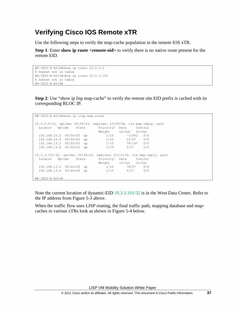
LISP VM Mobility Solution White Paper © 2011 Cisco and/or its affiliates. All rights reserved. This document is Cisco Public Information. 37
Verifying Cisco IOS Remote xTR Use the following steps to verify the map-cache population in the remote IOS xTR.
Step 1: Enter show ip route <remote-eid> to verify there is no native route present for the remote EID.
BR-3825-E-R214#show ip route 10.3.3.0 % Subnet not in table BR-3825-E-R214#show ip route 10.3.3.101 % Subnet not in table BR-3825-E-R214#
Step 2: Use “show ip lisp map-cache” to verify the remote site EID prefix is cached with its corresponding RLOC IP.
BR-3825-E-R214#show ip lisp map-cache 10.3.0.0/16, uptime: 00:50:03, expires: 23:09:56, via map-reply, auth Locator Uptime State Priority/ Data Control Weight in/out in/out 192.168.23.2 00:50:03 up 1/10 -11902 0/0 192.168.23.6 00:50:03 up 1/10 12/0* 0/0 192.168.13.2 00:50:03 up 1/10 78/14* 0/0 192.168.13.6 00:50:03 up 1/10 0/1* 0/0 10.3.3.101/32, uptime: 00:44:52, expires: 23:15:50, via map-reply, auth Locator Uptime State Priority/ Data Control Weight in/out in/out 192.168.13.2 00:44:09 up 1/10 78/0* 0/0 192.168.13.6 00:44:09 up 1/10 0/1* 0/0 BR-3825-E-R214#
Note the current location of dynamic-EID 10.3.3.101/32 is in the West Data Center. Refer to the IP address from Figure 5-3 above.
When the traffic flow uses LISP routing, the final traffic path, mapping database and map-caches in various xTRs look as shown in Figure 5-4 below.
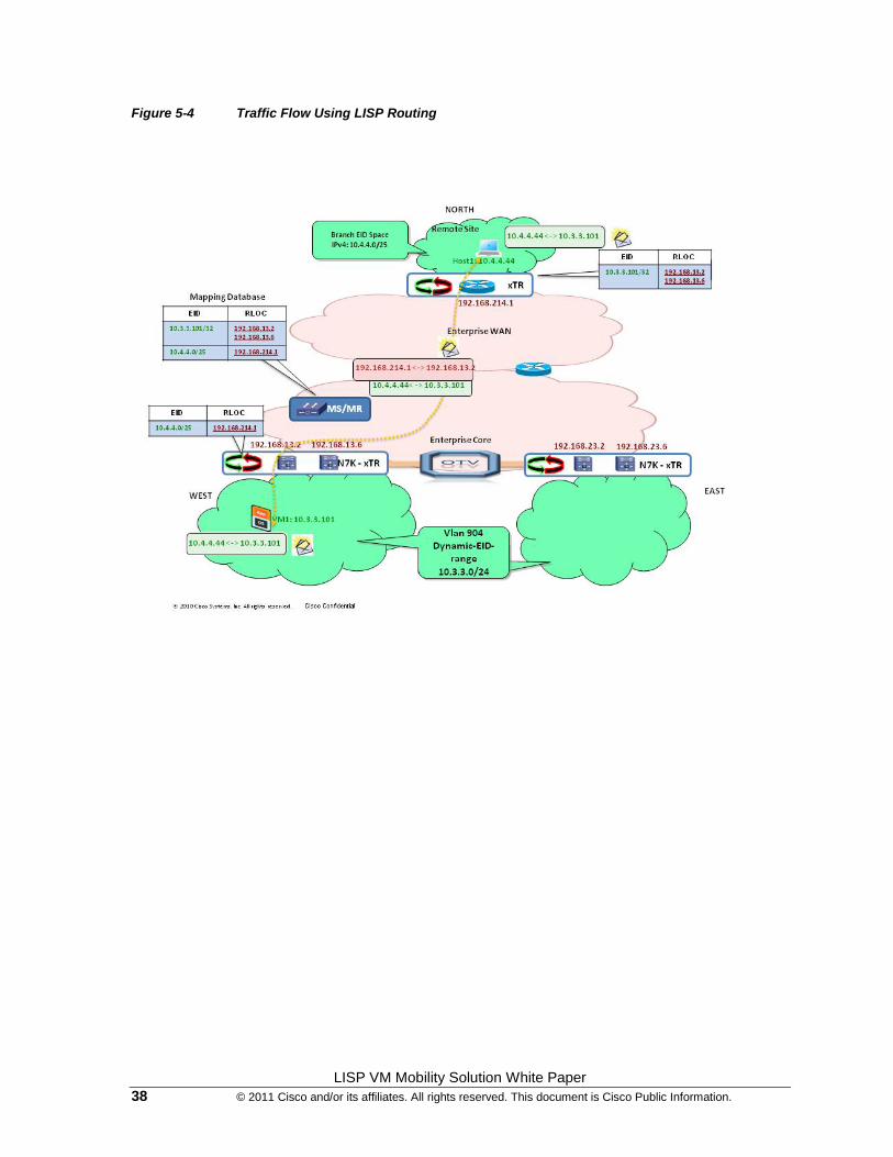
LISP VM Mobility Solution White Paper 38 © 2011 Cisco and/or its affiliates. All rights reserved. This document is Cisco Public Information.
Figure 5-4 Traffic Flow Using LISP Routing
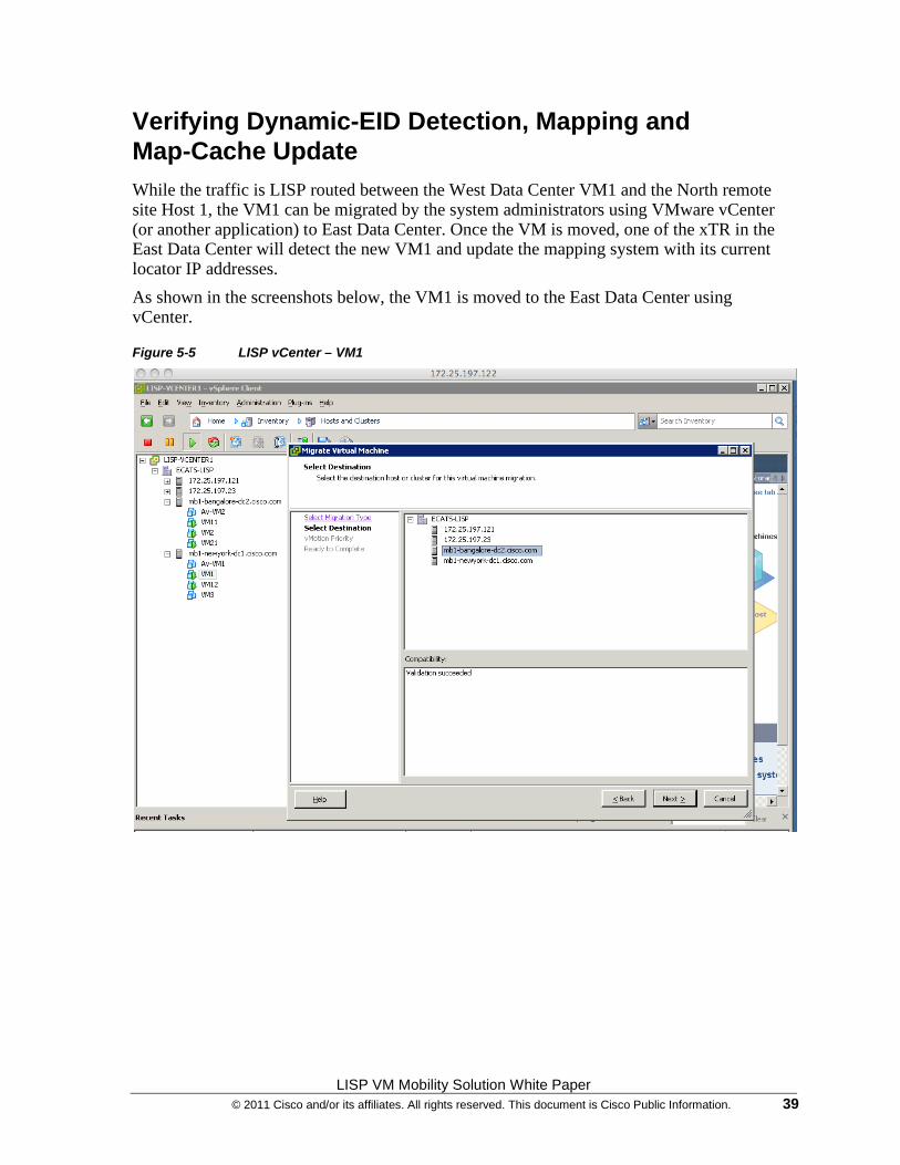
LISP VM Mobility Solution White Paper © 2011 Cisco and/or its affiliates. All rights reserved. This document is Cisco Public Information. 39
Verifying Dynamic-EID Detection, Mapping and Map-Cache Update While the traffic is LISP routed between the West Data Center VM1 and the North remote site Host 1, the VM1 can be migrated by the system administrators using VMware vCenter (or another application) to East Data Center. Once the VM is moved, one of the xTR in the East Data Center will detect the new VM1 and update the mapping system with its current locator IP addresses.
As shown in the screenshots below, the VM1 is moved to the East Data Center using vCenter.
Figure 5-5 LISP vCenter – VM1
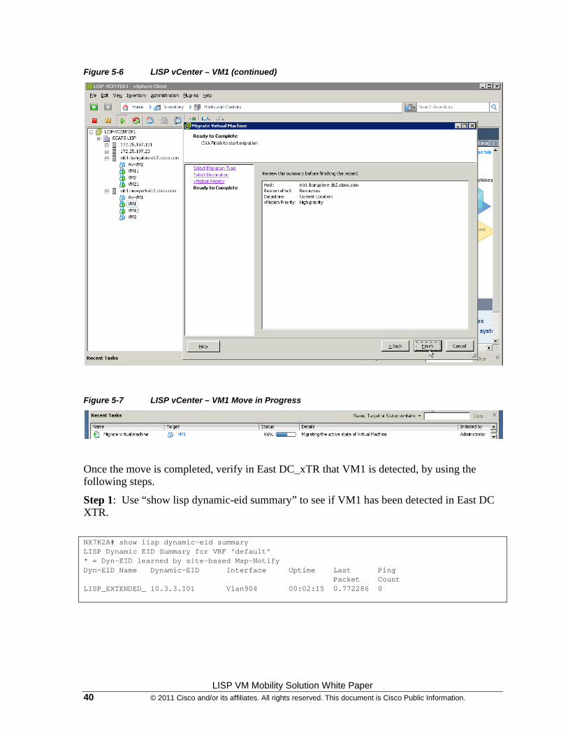
LISP VM Mobility Solution White Paper 40 © 2011 Cisco and/or its affiliates. All rights reserved. This document is Cisco Public Information.
Figure 5-6 LISP vCenter – VM1 (continued)
Figure 5-7 LISP vCenter – VM1 Move in Progress
Once the move is completed, verify in East DC_xTR that VM1 is detected, by using the following steps.
Step 1: Use “show lisp dynamic-eid summary” to see if VM1 has been detected in East DC XTR.
NX7K2A# show lisp dynamic-eid summary LISP Dynamic EID Summary for VRF "default" * = Dyn-EID learned by site-based Map-Notify Dyn-EID Name Dynamic-EID Interface Uptime Last Ping Packet Count LISP_EXTENDED_ 10.3.3.101 Vlan904 00:02:15 0.772286 0

LISP VM Mobility Solution White Paper © 2011 Cisco and/or its affiliates. All rights reserved. This document is Cisco Public Information. 41
Step 2: Since the East DC is multi-homed, we can verify that the peer xTR learned the dynamic-EID via the Map-Notify message.
NX7K2B# show lisp dynamic-eid summary LISP Dynamic EID Summary for VRF "default" * = Dyn-EID learned by site-based Map-Notify Dyn-EID Name Dynamic-EID Interface Uptime Last Ping Packet Count LISP_EXTENDED_*10.3.3.101 Vlan904 00:04:27 00:00:35 0
Also, it is possible to verify that the xTRs in the West DC site removed the dynamic-ID entry, as a result of the reception of the Map-Notify multicast message via OTV.
As depicted in output below, dynamic-EID entries are removed in the West DC xTRs.
NX7K1A# show lisp dynamic-eid summary LISP Dynamic EID Summary for VRF "default" * = Dyn-EID learned by site-based Map-Notify Dyn-EID Name Dynamic-EID Interface Uptime Last Pending Packet Ping Count
NX7K1B# show lisp dynamic-eid summary LISP Dynamic EID Summary for VRF "default" * = Dyn-EID learned by site-based Map-Notify Dyn-EID Name Dynamic-EID Interface Uptime Last Pending Packet Ping Count
Step 3: Verify in the Map-Server that the VM1 dynamic-EID locators are updated using show lisp site <dyn-eid-prefix>.
MB1-CORE-LISP-MS1# show lisp site 10.3.3.101/32 LISP Site Registration Information for VRF "default" * = truncated IPv6 address, -x = more-specifics count Site name: "DATA_CENTER" Description: none configured Allowed configured locators: any Requested EID-prefix: 10.3.3.101/32, instance-id: 0 Currently registered: yes First registered: 00:54:33 Last registered: 00:00:13 Who last registered: 192.168.23.2 Routing table tag: 0x00000000 Proxy Replying: no Wants Map-Notifications: yes Registering as a LISP-MN: no Registered TTL: 1440 minutes Registered locators: 192.168.23.2, port: 47062 (up), priority: 1, weight: 50 192.168.23.6, port: 47062 (up), priority: 1, weight: 50 Registration errors: Authentication failures: 0 Allowed locators mismatch: 0 MB1-CORE-LISP-MS1#
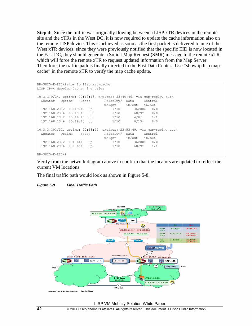
LISP VM Mobility Solution White Paper 42 © 2011 Cisco and/or its affiliates. All rights reserved. This document is Cisco Public Information.
Step 4: Since the traffic was originally flowing between a LISP xTR devices in the remote site and the xTRs in the West DC, it is now required to update the cache information also on the remote LISP device. This is achieved as soon as the first packet is delivered to one of the West xTR devices: since they were previously notified that the specific EID is now located in the East DC, they should generate a Solicit Map Request (SMR) message to the remote xTR which will force the remote xTR to request updated information from the Map Server. Therefore, the traffic path is finally directed to the East Data Center. Use “show ip lisp map-cache” in the remote xTR to verify the map cache update.
BR-3825-E-R214#show ip lisp map-cache LISP IPv4 Mapping Cache, 2 entries 10.3.3.0/24, uptime: 00:19:13, expires: 23:40:46, via map-reply, auth Locator Uptime State Priority/ Data Control Weight in/out in/out 192.168.23.2 00:19:13 up 1/10 362084 0/0 192.168.23.6 00:19:13 up 1/10 60/9* 0/0 192.168.13.2 00:19:13 up 1/10 4/0* 1/1 192.168.13.6 00:19:13 up 1/10 0/13* 0/0 10.3.3.101/32, uptime: 00:18:55, expires: 23:53:49, via map-reply, auth Locator Uptime State Priority/ Data Control Weight in/out in/out 192.168.23.2 00:06:10 up 1/10 362084 0/0 192.168.23.6 00:06:10 up 1/10 60/9* 1/1 BR-3825-E-R214#
Verify from the network diagram above to confirm that the locators are updated to reflect the current VM locations.
The final traffic path would look as shown in Figure 5-8.
Figure 5-8 Final Traffic Path
LISP VM Mobility Solution White Paper © 2011 Cisco and/or its affiliates. All rights reserved. This document is Cisco Public Information. 43
Summary
In summary, the LISP VM-Mobility solution within Extended Subnet provides the following key benefits:
• LISP co-existence with OTV
• Automated move detection
• Dynamic-EID discovery in multi-homed data center
• Direct Path, which provides a seamless ingress path optimization and avoids the traffic triangulation problem
• Connections maintained across move: this makes this deployment suitable to solve “hot” migration use cases.
• No routing re-convergence
• No DNS updates required
• Transparent to the hosts
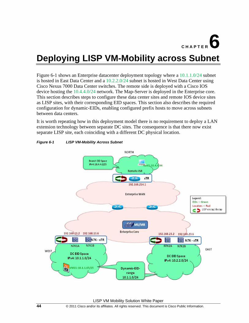
LISP VM Mobility Solution White Paper 44 © 2011 Cisco and/or its affiliates. All rights reserved. This document is Cisco Public Information.
C H A P T E R 6
Deploying LISP VM-Mobility across Subnet
Figure 6-1 shows an Enterprise datacenter deployment topology where a 10.1.1.0/24 subnet is hosted in East Data Center and a 10.2.2.0/24 subnet is hosted in West Data Center using Cisco Nexus 7000 Data Center switches. The remote side is deployed with a Cisco IOS device hosting the 10.4.4.0/24 network. The Map-Server is deployed in the Enterprise core. This section describes steps to configure these data center sites and remote IOS device sites as LISP sites, with their corresponding EID spaces. This section also describes the required configuration for dynamic-EIDs, enabling configured prefix hosts to move across subnets between data centers.
It is worth repeating how in this deployment model there is no requirement to deploy a LAN extension technology between separate DC sites. The consequence is that there now exist separate LISP site, each coinciding with a different DC physical location.
Figure 6-1 LISP VM-Mobility Across Subnet
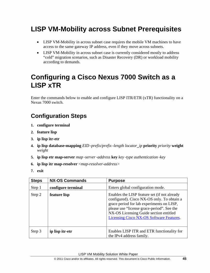
LISP VM Mobility Solution White Paper © 2011 Cisco and/or its affiliates. All rights reserved. This document is Cisco Public Information. 45
LISP VM-Mobility across Subnet Prerequisites
• LISP VM-Mobility in across subnet case requires the mobile VM machines to have access to the same gateway IP address, even if they move across subnets.
• LISP VM-Mobility in across subnet case is currently considered mostly to address “cold” migration scenarios, such as Disaster Recovery (DR) or workload mobility according to demands.
Configuring a Cisco Nexus 7000 Switch as a LISP xTR
Enter the commands below to enable and configure LISP ITR/ETR (xTR) functionality on a Nexus 7000 switch.
Configuration Steps 1. configure terminal
2. feature lisp
3. ip lisp itr-etr
4. ip lisp database-mapping EID‐prefix/prefix‐length locator_ip priority priority weight weight
5. ip lisp etr map-server map‐server‐address key key‐type authentication‐key
6. ip lisp itr map-resolver <map-resolver-address>
7. exit Steps NX-OS Commands Purpose
Step 1 configure terminal Enters global configuration mode.
Step 2 feature lisp Enables the LISP feature set (if not already configured). Cisco NX-OS only. To obtain a grace period for lab experiments on LISP, please use “license grace-period”. See the NX-OS Licensing Guide section entitled Licensing Cisco NX-OS Software Features.
Step 3 ip lisp itr-etr Enables LISP ITR and ETR functionality for the IPv4 address family.
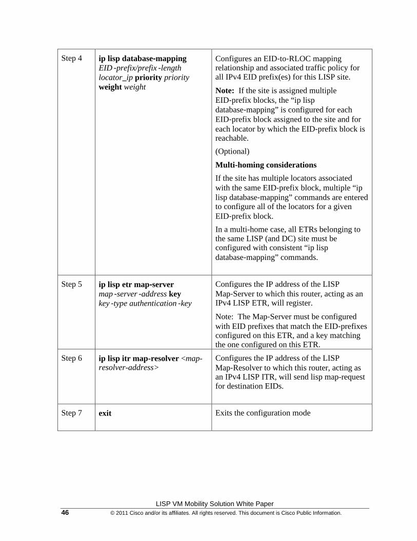
LISP VM Mobility Solution White Paper 46 © 2011 Cisco and/or its affiliates. All rights reserved. This document is Cisco Public Information.
Step 4 ip lisp database-mapping EID‐prefix/prefix‐length locator_ip priority priority weight weight
Configures an EID‐to‐RLOC mapping relationship and associated traffic policy for all IPv4 EID prefix(es) for this LISP site.
Note: If the site is assigned multiple EID‐prefix blocks, the “ip lisp database‐mapping” is configured for each EID‐prefix block assigned to the site and for each locator by which the EID‐prefix block is reachable.
(Optional)
Multi-homing considerations
If the site has multiple locators associated with the same EID‐prefix block, multiple “ip lisp database‐mapping” commands are entered to configure all of the locators for a given EID‐prefix block.
In a multi-home case, all ETRs belonging to the same LISP (and DC) site must be configured with consistent “ip lisp database‐mapping” commands.
Step 5 ip lisp etr map-server map‐server‐address key key‐type authentication‐key
Configures the IP address of the LISP Map‐Server to which this router, acting as an IPv4 LISP ETR, will register.
Note: The Map‐Server must be configured with EID prefixes that match the EID‐prefixes configured on this ETR, and a key matching the one configured on this ETR.
Step 6 ip lisp itr map-resolver <map-resolver-address>
Configures the IP address of the LISP Map‐Resolver to which this router, acting as an IPv4 LISP ITR, will send lisp map-request for destination EIDs.
Step 7 exit Exits the configuration mode
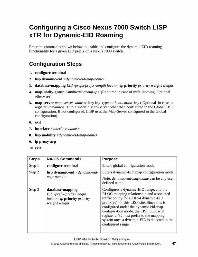
LISP VM Mobility Solution White Paper © 2011 Cisco and/or its affiliates. All rights reserved. This document is Cisco Public Information. 47
Configuring a Cisco Nexus 7000 Switch LISP xTR for Dynamic-EID Roaming
Enter the commands shown below to enable and configure the dynamic-EID roaming functionality for a given EID prefix on a Nexus 7000 switch.
Configuration Steps 1. configure terminal
2. lisp dynamic-eid <dynamic-eid-map-name>
3. database-mapping EID‐prefix/prefix‐length locator_ip priority priority weight weight
4. map-notify-group <multicast-group-ip> (Required in case of multi-homing. Optional otherwise)
5. map-server map‐server‐address key key‐type authentication‐key ( Optional in case to register Dynamic-EID to a specific Map-Server other than configured in the Global LISP configuration. If not configured, LISP uses the Map-Server configured in the Global configuration).
6. exit
7. interface <interface-name>
8. lisp mobility <dynamic-eid-map-name>
9. ip proxy-arp
10. exit
Steps NX-OS Commands Purpose
Step 1 configure terminal Enters global configuration mode.
Step 2 lisp dynamic-eid <dynamic-eid-map-name>
Enters dynamic-EID map configuration mode.
Note: dynamic-eid-map-name can be any user defined name.
Step 3 database-mapping EID‐prefix/prefix‐length locator_ip priority priority weight weight
Configures a dynamic-EID range, and the RLOC mapping relationship and associated traffic policy for all IPv4 dynamic-EID prefix(es) for this LISP site. Since this is configured under the dynamic-eid-map configuration mode, the LISP ETR will register a /32 host prefix to the mapping system once a dynamic-EID is detected in the configured range,
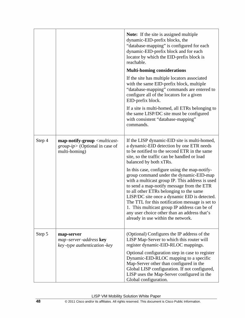
LISP VM Mobility Solution White Paper 48 © 2011 Cisco and/or its affiliates. All rights reserved. This document is Cisco Public Information.
Note: If the site is assigned multiple dynamic-EID‐prefix blocks, the “database‐mapping” is configured for each dynamic-EID‐prefix block and for each locator by which the EID‐prefix block is reachable.
Multi-homing considerations
If the site has multiple locators associated with the same EID‐prefix block, multiple “database‐mapping” commands are entered to configure all of the locators for a given EID‐prefix block.
If a site is multi-homed, all ETRs belonging to the same LISP/DC site must be configured with consistent “database‐mapping” commands.
Step 4 map-notify-group <multicast-group-ip> (Optional in case of multi-homing)
If the LISP dynamic-EID site is multi-homed, a dynamic-EID detection by one ETR needs to be notified to the second ETR in the same site, so the traffic can be handled or load balanced by both xTRs.
In this case, configure using the map-notify-group command under the dynamic-EID-map with a multicast group IP. This address is used to send a map-notify message from the ETR to all other ETRs belonging to the same LISP/DC site once a dynamic EID is detected. The TTL for this notification message is set to 1. This multicast group IP address can be of any user choice other than an address that’s already in use within the network.
Step 5 map-server map‐server‐address key key‐type authentication‐key
(Optional) Configures the IP address of the LISP Map‐Server to which this router will register dynamic-EID-RLOC mappings.
Optional configuration step in case to register Dynamic-EID-RLOC mapping to a specific Map-Server other than configured in the Global LISP configuration. If not configured, LISP uses the Map-Server configured in the Global configuration.
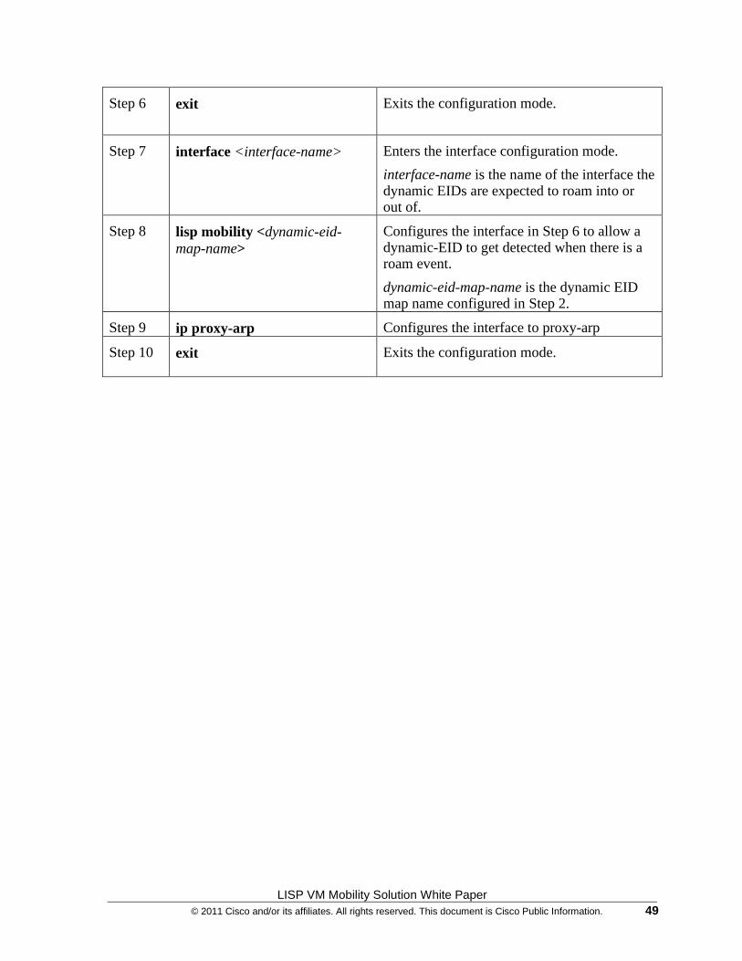
LISP VM Mobility Solution White Paper © 2011 Cisco and/or its affiliates. All rights reserved. This document is Cisco Public Information. 49
Step 6 exit Exits the configuration mode.
Step 7 interface <interface-name>
Enters the interface configuration mode.
interface-name is the name of the interface the dynamic EIDs are expected to roam into or out of.
Step 8 lisp mobility <dynamic-eid-map-name>
Configures the interface in Step 6 to allow a dynamic-EID to get detected when there is a roam event.
dynamic-eid-map-name is the dynamic EID map name configured in Step 2.
Step 9 ip proxy-arp Configures the interface to proxy-arp
Step 10 exit Exits the configuration mode.
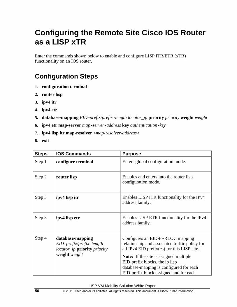
LISP VM Mobility Solution White Paper 50 © 2011 Cisco and/or its affiliates. All rights reserved. This document is Cisco Public Information.
Configuring the Remote Site Cisco IOS Router as a LISP xTR
Enter the commands shown below to enable and configure LISP ITR/ETR (xTR) functionality on an IOS router.
Configuration Steps 1. configuration terminal
2. router lisp
3. ipv4 itr
4. ipv4 etr
5. database-mapping EID‐prefix/prefix‐length locator_ip priority priority weight weight
6. ipv4 etr map-server map‐server‐address key authentication‐key
7. ipv4 lisp itr map-resolver <map-resolver-address>
8. exit
Steps IOS Commands Purpose
Step 1 configure terminal Enters global configuration mode.
Step 2 router lisp Enables and enters into the router lisp configuration mode.
Step 3 ipv4 lisp itr Enables LISP ITR functionality for the IPv4 address family.
Step 3 ipv4 lisp etr Enables LISP ETR functionality for the IPv4 address family.
Step 4 database-mapping EID‐prefix/prefix‐length locator_ip priority priority weight weight
Configures an EID‐to‐RLOC mapping relationship and associated traffic policy for all IPv4 EID prefix(es) for this LISP site.
Note: If the site is assigned multiple EID‐prefix blocks, the ip lisp database‐mapping is configured for each EID‐prefix block assigned and for each
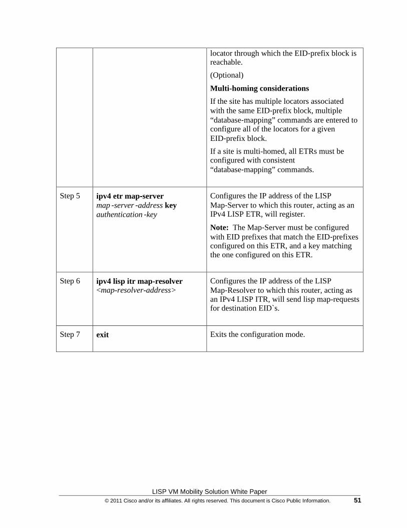
LISP VM Mobility Solution White Paper © 2011 Cisco and/or its affiliates. All rights reserved. This document is Cisco Public Information. 51
locator through which the EID‐prefix block is reachable.
(Optional)
Multi-homing considerations
If the site has multiple locators associated with the same EID‐prefix block, multiple “database‐mapping” commands are entered to configure all of the locators for a given EID‐prefix block.
If a site is multi-homed, all ETRs must be configured with consistent “database‐mapping” commands.
Step 5 ipv4 etr map-server map‐server‐address key authentication‐key
Configures the IP address of the LISP Map‐Server to which this router, acting as an IPv4 LISP ETR, will register.
Note: The Map‐Server must be configured with EID prefixes that match the EID‐prefixes configured on this ETR, and a key matching the one configured on this ETR.
Step 6 ipv4 lisp itr map-resolver <map-resolver-address>
Configures the IP address of the LISP Map‐Resolver to which this router, acting as an IPv4 LISP ITR, will send lisp map-requests for destination EID`s.
Step 7 exit Exits the configuration mode.
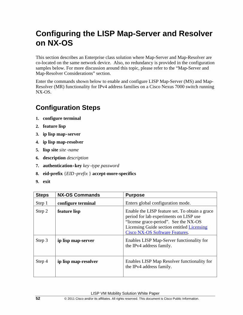
LISP VM Mobility Solution White Paper 52 © 2011 Cisco and/or its affiliates. All rights reserved. This document is Cisco Public Information.
Configuring the LISP Map-Server and Resolver on NX-OS
This section describes an Enterprise class solution where Map-Server and Map-Resolver are co-located on the same network device. Also, no redundancy is provided in the configuration samples below. For more discussion around this topic, please refer to the “Map-Server and Map-Resolver Considerations” section.
Enter the commands shown below to enable and configure LISP Map‐Server (MS) and Map-Resolver (MR) functionality for IPv4 address families on a Cisco Nexus 7000 switch running NX-OS.
Configuration Steps 1. configure terminal
2. feature lisp
3. ip lisp map‐server
4. ip lisp map-resolver
5. lisp site site‐name
6. description description
7. authentication‐key key‐type password
8. eid-prefix {EID‐prefix } accept-more-specifics
9. exit
Steps NX-OS Commands Purpose
Step 1 configure terminal Enters global configuration mode.
Step 2 feature lisp Enable the LISP feature set. To obtain a grace period for lab experiments on LISP use “license grace-period”. See the NX-OS Licensing Guide section entitled Licensing Cisco NX-OS Software Features.
Step 3 ip lisp map-server Enables LISP Map-Server functionality for the IPv4 address family.
Step 4 ip lisp map-resolver Enables LISP Map Resolver functionality for the IPv4 address family.
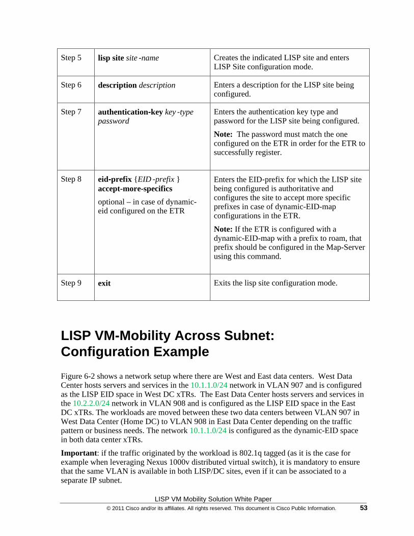
LISP VM Mobility Solution White Paper © 2011 Cisco and/or its affiliates. All rights reserved. This document is Cisco Public Information. 53
Step 5 lisp site site‐name
Creates the indicated LISP site and enters LISP Site configuration mode.
Step 6 description description
Enters a description for the LISP site being configured.
Step 7 authentication-key key‐type password
Enters the authentication key type and password for the LISP site being configured.
Note: The password must match the one configured on the ETR in order for the ETR to successfully register.
Step 8 eid-prefix {EID‐prefix } accept-more-specifics
optional – in case of dynamic-eid configured on the ETR
Enters the EID‐prefix for which the LISP site being configured is authoritative and configures the site to accept more specific prefixes in case of dynamic-EID-map configurations in the ETR.
Note: If the ETR is configured with a dynamic-EID-map with a prefix to roam, that prefix should be configured in the Map-Server using this command.
Step 9 exit Exits the lisp site configuration mode.
LISP VM-Mobility Across Subnet: Configuration Example
Figure 6-2 shows a network setup where there are West and East data centers. West Data Center hosts servers and services in the 10.1.1.0/24 network in VLAN 907 and is configured as the LISP EID space in West DC xTRs. The East Data Center hosts servers and services in the 10.2.2.0/24 network in VLAN 908 and is configured as the LISP EID space in the East DC xTRs. The workloads are moved between these two data centers between VLAN 907 in West Data Center (Home DC) to VLAN 908 in East Data Center depending on the traffic pattern or business needs. The network 10.1.1.0/24 is configured as the dynamic-EID space in both data center xTRs.
Important: if the traffic originated by the workload is 802.1q tagged (as it is the case for example when leveraging Nexus 1000v distributed virtual switch), it is mandatory to ensure that the same VLAN is available in both LISP/DC sites, even if it can be associated to a separate IP subnet.
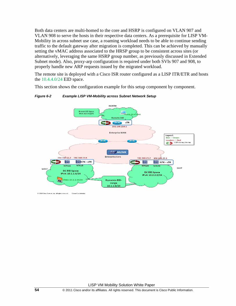
LISP VM Mobility Solution White Paper 54 © 2011 Cisco and/or its affiliates. All rights reserved. This document is Cisco Public Information.
Both data centers are multi-homed to the core and HSRP is configured on VLAN 907 and VLAN 908 to serve the hosts in their respective data centers. As a prerequisite for LISP VM-Mobility in across subnet use case, a roaming workload needs to be able to continue sending traffic to the default gateway after migration is completed. This can be achieved by manually setting the vMAC address associated to the HRSP group to be consistent across sites (or alternatively, leveraging the same HSRP group number, as previously discussed in Extended Subnet mode). Also, proxy-arp configuration is required under both SVIs 907 and 908, to properly handle new ARP requests issued by the migrated workload.
The remote site is deployed with a Cisco ISR router configured as a LISP ITR/ETR and hosts the 10.4.4.0/24 EID space.
This section shows the configuration example for this setup component by component.
Figure 6-2 Example LISP VM-Mobility across Subnet Network Setup
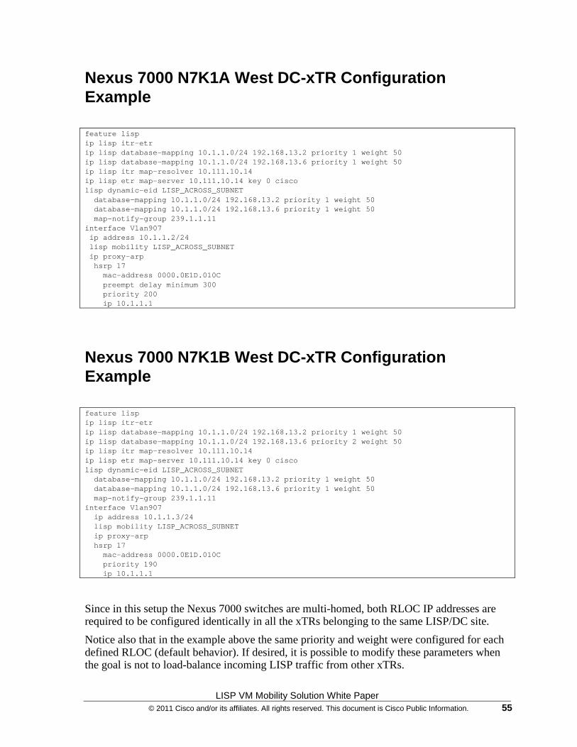
LISP VM Mobility Solution White Paper © 2011 Cisco and/or its affiliates. All rights reserved. This document is Cisco Public Information. 55
Nexus 7000 N7K1A West DC-xTR Configuration Example feature lisp ip lisp itr-etr ip lisp database-mapping 10.1.1.0/24 192.168.13.2 priority 1 weight 50 ip lisp database-mapping 10.1.1.0/24 192.168.13.6 priority 1 weight 50 ip lisp itr map-resolver 10.111.10.14 ip lisp etr map-server 10.111.10.14 key 0 cisco lisp dynamic-eid LISP_ACROSS_SUBNET database-mapping 10.1.1.0/24 192.168.13.2 priority 1 weight 50 database-mapping 10.1.1.0/24 192.168.13.6 priority 1 weight 50 map-notify-group 239.1.1.11 interface Vlan907 ip address 10.1.1.2/24 lisp mobility LISP_ACROSS_SUBNET ip proxy-arp hsrp 17 mac-address 0000.0E1D.010C preempt delay minimum 300 priority 200 ip 10.1.1.1
Nexus 7000 N7K1B West DC-xTR Configuration Example feature lisp ip lisp itr-etr ip lisp database-mapping 10.1.1.0/24 192.168.13.2 priority 1 weight 50 ip lisp database-mapping 10.1.1.0/24 192.168.13.6 priority 2 weight 50 ip lisp itr map-resolver 10.111.10.14 ip lisp etr map-server 10.111.10.14 key 0 cisco lisp dynamic-eid LISP_ACROSS_SUBNET database-mapping 10.1.1.0/24 192.168.13.2 priority 1 weight 50 database-mapping 10.1.1.0/24 192.168.13.6 priority 1 weight 50 map-notify-group 239.1.1.11 interface Vlan907 ip address 10.1.1.3/24 lisp mobility LISP_ACROSS_SUBNET ip proxy-arp hsrp 17 mac-address 0000.0E1D.010C priority 190 ip 10.1.1.1
Since in this setup the Nexus 7000 switches are multi-homed, both RLOC IP addresses are required to be configured identically in all the xTRs belonging to the same LISP/DC site.
Notice also that in the example above the same priority and weight were configured for each defined RLOC (default behavior). If desired, it is possible to modify these parameters when the goal is not to load-balance incoming LISP traffic from other xTRs.
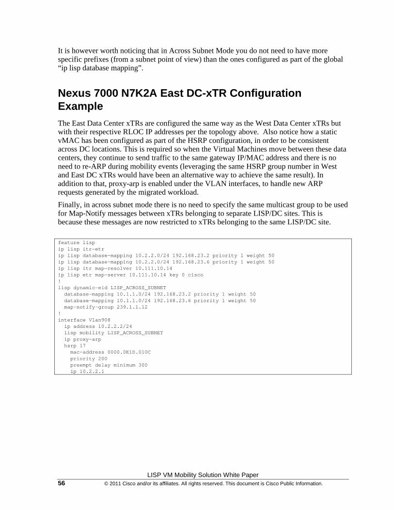
LISP VM Mobility Solution White Paper 56 © 2011 Cisco and/or its affiliates. All rights reserved. This document is Cisco Public Information.
It is however worth noticing that in Across Subnet Mode you do not need to have more specific prefixes (from a subnet point of view) than the ones configured as part of the global “ip lisp database mapping”.
Nexus 7000 N7K2A East DC-xTR Configuration Example The East Data Center xTRs are configured the same way as the West Data Center xTRs but with their respective RLOC IP addresses per the topology above. Also notice how a static vMAC has been configured as part of the HSRP configuration, in order to be consistent across DC locations. This is required so when the Virtual Machines move between these data centers, they continue to send traffic to the same gateway IP/MAC address and there is no need to re-ARP during mobility events (leveraging the same HSRP group number in West and East DC xTRs would have been an alternative way to achieve the same result). In addition to that, proxy-arp is enabled under the VLAN interfaces, to handle new ARP requests generated by the migrated workload.
Finally, in across subnet mode there is no need to specify the same multicast group to be used for Map-Notify messages between xTRs belonging to separate LISP/DC sites. This is because these messages are now restricted to xTRs belonging to the same LISP/DC site.
feature lisp ip lisp itr-etr ip lisp database-mapping 10.2.2.0/24 192.168.23.2 priority 1 weight 50 ip lisp database-mapping 10.2.2.0/24 192.168.23.6 priority 1 weight 50 ip lisp itr map-resolver 10.111.10.14 ip lisp etr map-server 10.111.10.14 key 0 cisco ! lisp dynamic-eid LISP_ACROSS_SUBNET database-mapping 10.1.1.0/24 192.168.23.2 priority 1 weight 50 database-mapping 10.1.1.0/24 192.168.23.6 priority 1 weight 50 map-notify-group 239.1.1.12 ! interface Vlan908 ip address 10.2.2.2/24 lisp mobility LISP_ACROSS_SUBNET ip proxy-arp hsrp 17 mac-address 0000.0E1D.010C priority 200 preempt delay minimum 300 ip 10.2.2.1
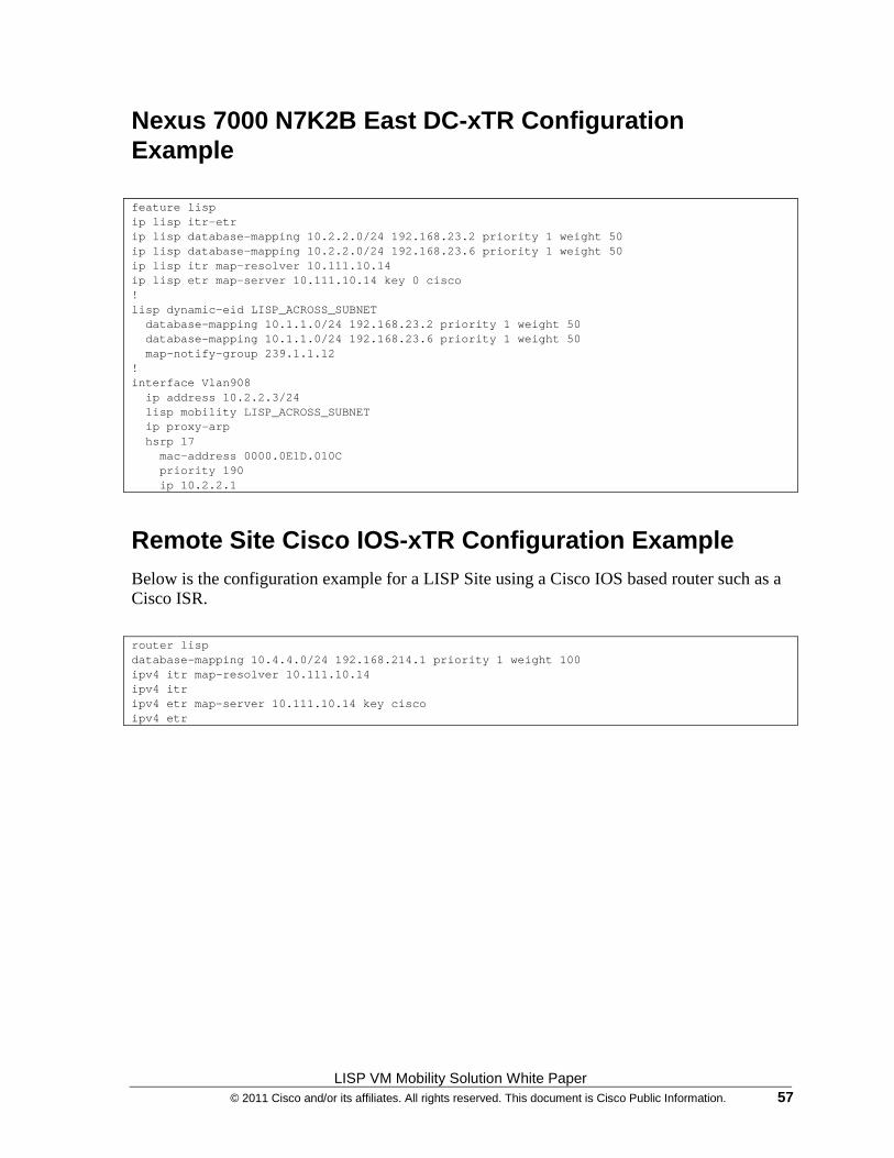
LISP VM Mobility Solution White Paper © 2011 Cisco and/or its affiliates. All rights reserved. This document is Cisco Public Information. 57
Nexus 7000 N7K2B East DC-xTR Configuration Example feature lisp ip lisp itr-etr ip lisp database-mapping 10.2.2.0/24 192.168.23.2 priority 1 weight 50 ip lisp database-mapping 10.2.2.0/24 192.168.23.6 priority 1 weight 50 ip lisp itr map-resolver 10.111.10.14 ip lisp etr map-server 10.111.10.14 key 0 cisco ! lisp dynamic-eid LISP_ACROSS_SUBNET database-mapping 10.1.1.0/24 192.168.23.2 priority 1 weight 50 database-mapping 10.1.1.0/24 192.168.23.6 priority 1 weight 50 map-notify-group 239.1.1.12 ! interface Vlan908 ip address 10.2.2.3/24 lisp mobility LISP_ACROSS_SUBNET ip proxy-arp hsrp 17 mac-address 0000.0E1D.010C priority 190 ip 10.2.2.1
Remote Site Cisco IOS-xTR Configuration Example Below is the configuration example for a LISP Site using a Cisco IOS based router such as a Cisco ISR.
router lisp database-mapping 10.4.4.0/24 192.168.214.1 priority 1 weight 100 ipv4 itr map-resolver 10.111.10.14 ipv4 itr ipv4 etr map-server 10.111.10.14 key cisco ipv4 etr
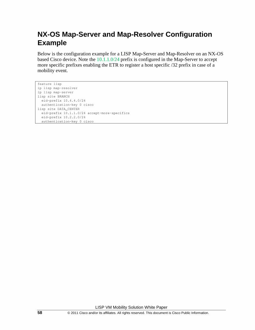
LISP VM Mobility Solution White Paper 58 © 2011 Cisco and/or its affiliates. All rights reserved. This document is Cisco Public Information.
NX-OS Map-Server and Map-Resolver Configuration Example Below is the configuration example for a LISP Map-Server and Map-Resolver on an NX-OS based Cisco device. Note the 10.1.1.0/24 prefix is configured in the Map-Server to accept more specific prefixes enabling the ETR to register a host specific /32 prefix in case of a mobility event.
feature lisp ip lisp map-resolver ip lisp map-server lisp site BRANCH eid-prefix 10.4.4.0/24 authentication-key 0 cisco lisp site DATA_CENTER eid-prefix 10.1.1.0/24 accept-more-specifics eid-prefix 10.2.2.0/24 authentication-key 0 cisco
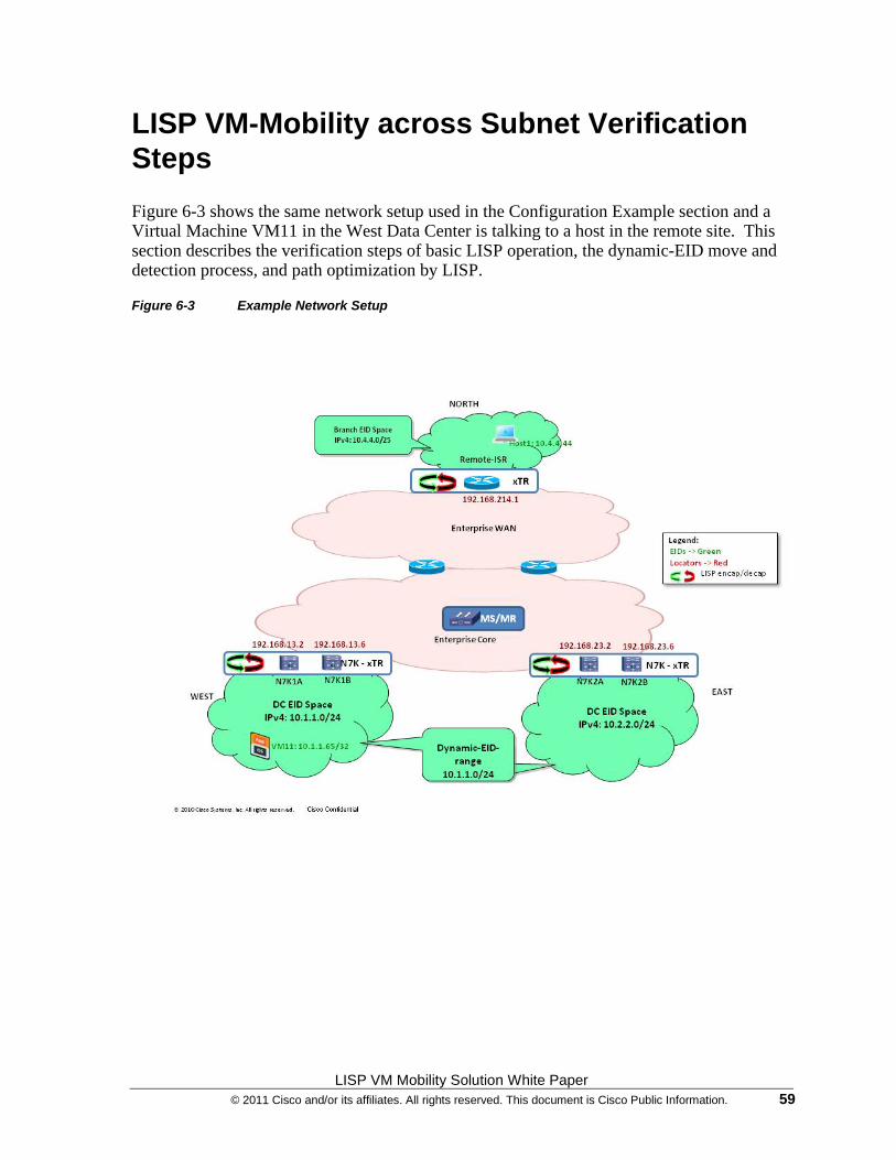
LISP VM Mobility Solution White Paper © 2011 Cisco and/or its affiliates. All rights reserved. This document is Cisco Public Information. 59
LISP VM-Mobility across Subnet Verification Steps
Figure 6-3 shows the same network setup used in the Configuration Example section and a Virtual Machine VM11 in the West Data Center is talking to a host in the remote site. This section describes the verification steps of basic LISP operation, the dynamic-EID move and detection process, and path optimization by LISP.
Figure 6-3 Example Network Setup
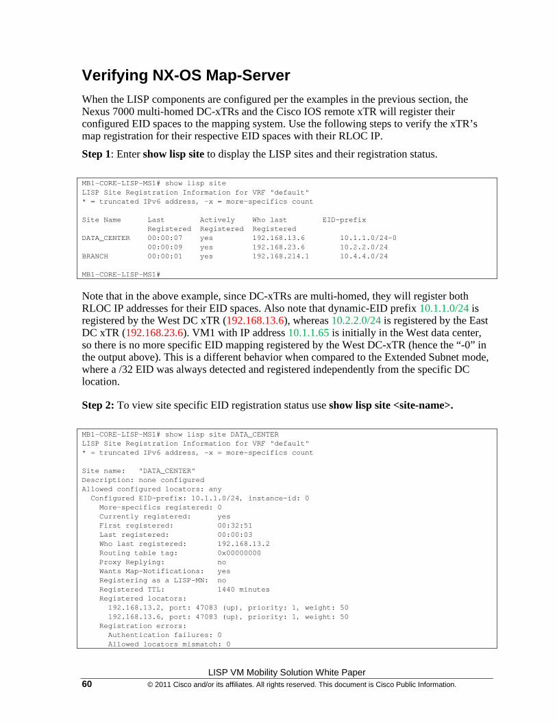
LISP VM Mobility Solution White Paper 60 © 2011 Cisco and/or its affiliates. All rights reserved. This document is Cisco Public Information.
Verifying NX-OS Map-Server When the LISP components are configured per the examples in the previous section, the Nexus 7000 multi-homed DC-xTRs and the Cisco IOS remote xTR will register their configured EID spaces to the mapping system. Use the following steps to verify the xTR’s map registration for their respective EID spaces with their RLOC IP.
Step 1: Enter show lisp site to display the LISP sites and their registration status.
MB1-CORE-LISP-MS1# show lisp site LISP Site Registration Information for VRF "default" * = truncated IPv6 address, -x = more-specifics count Site Name Last Actively Who last EID-prefix Registered Registered Registered DATA_CENTER 00:00:07 yes 192.168.13.6 10.1.1.0/24-0 00:00:09 yes 192.168.23.6 10.2.2.0/24 BRANCH 00:00:01 yes 192.168.214.1 10.4.4.0/24 MB1-CORE-LISP-MS1#
Note that in the above example, since DC-xTRs are multi-homed, they will register both RLOC IP addresses for their EID spaces. Also note that dynamic-EID prefix 10.1.1.0/24 is registered by the West DC xTR (192.168.13.6), whereas 10.2.2.0/24 is registered by the East DC xTR (192.168.23.6). VM1 with IP address 10.1.1.65 is initially in the West data center, so there is no more specific EID mapping registered by the West DC-xTR (hence the “-0” in the output above). This is a different behavior when compared to the Extended Subnet mode, where a /32 EID was always detected and registered independently from the specific DC location.
Step 2: To view site specific EID registration status use show lisp site <site-name>.
MB1-CORE-LISP-MS1# show lisp site DATA_CENTER LISP Site Registration Information for VRF "default" * = truncated IPv6 address, -x = more-specifics count Site name: "DATA_CENTER" Description: none configured Allowed configured locators: any Configured EID-prefix: 10.1.1.0/24, instance-id: 0 More-specifics registered: 0 Currently registered: yes First registered: 00:32:51 Last registered: 00:00:03 Who last registered: 192.168.13.2 Routing table tag: 0x00000000 Proxy Replying: no Wants Map-Notifications: yes Registering as a LISP-MN: no Registered TTL: 1440 minutes Registered locators: 192.168.13.2, port: 47083 (up), priority: 1, weight: 50 192.168.13.6, port: 47083 (up), priority: 1, weight: 50 Registration errors: Authentication failures: 0 Allowed locators mismatch: 0

LISP VM Mobility Solution White Paper © 2011 Cisco and/or its affiliates. All rights reserved. This document is Cisco Public Information. 61
Configured EID-prefix: 10.2.2.0/24, instance-id: 0 Currently registered: yes First registered: 00:28:43 Last registered: 00:00:08 Who last registered: 192.168.23.2 Routing table tag: 0x00000000 Proxy Replying: no Wants Map-Notifications: yes Registering as a LISP-MN: no Registered TTL: 1440 minutes Registered locators: 192.168.23.2, port: 47083 (up), priority: 1, weight: 50 192.168.23.6, port: 47083 (up), priority: 1, weight: 50 Registration errors: Authentication failures: 0 Allowed locators mismatch: 0 MB1-CORE-LISP-MS1#
Verifying Nexus 7000 DC-xTRs If the end devices in the data center or in the Remote site try to send traffic (for example VM11 in the West Data Center and Host 1 in the North remote site), the xTRs will query the mapping system as they don’t have native routes to the other site. Once the Map-Server receives the Map-Request from the xTR, it will forward the request to the last registered RLOC (xTR). The ETR will reply to the Map-Request and the ITRs will populate their map-cache tables. Subsequent packets between the sites are encapsulated and sent to the other site ETRs. The receiving side ETR will decapsulate the packet and deliver it to the destination.
Use the following steps to verify the Nexus 7000 DC-xTRs.
Step 1: Enter show ip route <remote-eid> to verify there is no native route present for the remote EID.
NX7K1A# show ip route 10.4.4.0/24 longer-prefixes IP Route Table for VRF "default" '*' denotes best ucast next-hop '**' denotes best mcast next-hop '[x/y]' denotes [preference/metric]
Step 2: Use show ip lisp map-cache to verify the remote site EID prefix is cached with its corresponding RLOC IP.
NX7K1A# show ip lisp map-cache LISP IP Mapping Cache for VRF "default" (iid 0), 3 entries 10.4.4.0/24, uptime: 00:02:26, expires: 23:57:33, via map-reply, auth Locator Uptime State Priority/ Data Control Weight in/out in/out 192.168.214.1 00:02:26 up 1/100 12/138 1/0
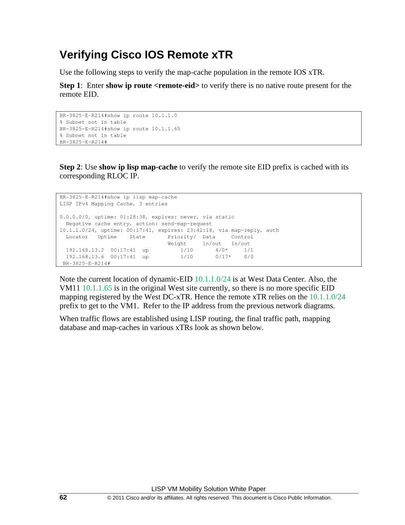
LISP VM Mobility Solution White Paper 62 © 2011 Cisco and/or its affiliates. All rights reserved. This document is Cisco Public Information.
Verifying Cisco IOS Remote xTR Use the following steps to verify the map-cache population in the remote IOS xTR.
Step 1: Enter show ip route <remote-eid> to verify there is no native route present for the remote EID.
BR-3825-E-R214#show ip route 10.1.1.0 % Subnet not in table BR-3825-E-R214#show ip route 10.1.1.65 % Subnet not in table BR-3825-E-R214#
Step 2: Use show ip lisp map-cache to verify the remote site EID prefix is cached with its corresponding RLOC IP.
BR-3825-E-R214#show ip lisp map-cache LISP IPv4 Mapping Cache, 3 entries 0.0.0.0/0, uptime: 01:28:38, expires: never, via static Negative cache entry, action: send-map-request 10.1.1.0/24, uptime: 00:17:41, expires: 23:42:18, via map-reply, auth Locator Uptime State Priority/ Data Control Weight in/out in/out 192.168.13.2 00:17:41 up 1/10 4/0* 1/1 192.168.13.6 00:17:41 up 1/10 0/17* 0/0 BR-3825-E-R214#
Note the current location of dynamic-EID 10.1.1.0/24 is at West Data Center. Also, the VM11 10.1.1.65 is in the original West site currently, so there is no more specific EID mapping registered by the West DC-xTR. Hence the remote xTR relies on the 10.1.1.0/24 prefix to get to the VM1. Refer to the IP address from the previous network diagrams.
When traffic flows are established using LISP routing, the final traffic path, mapping database and map-caches in various xTRs look as shown below.
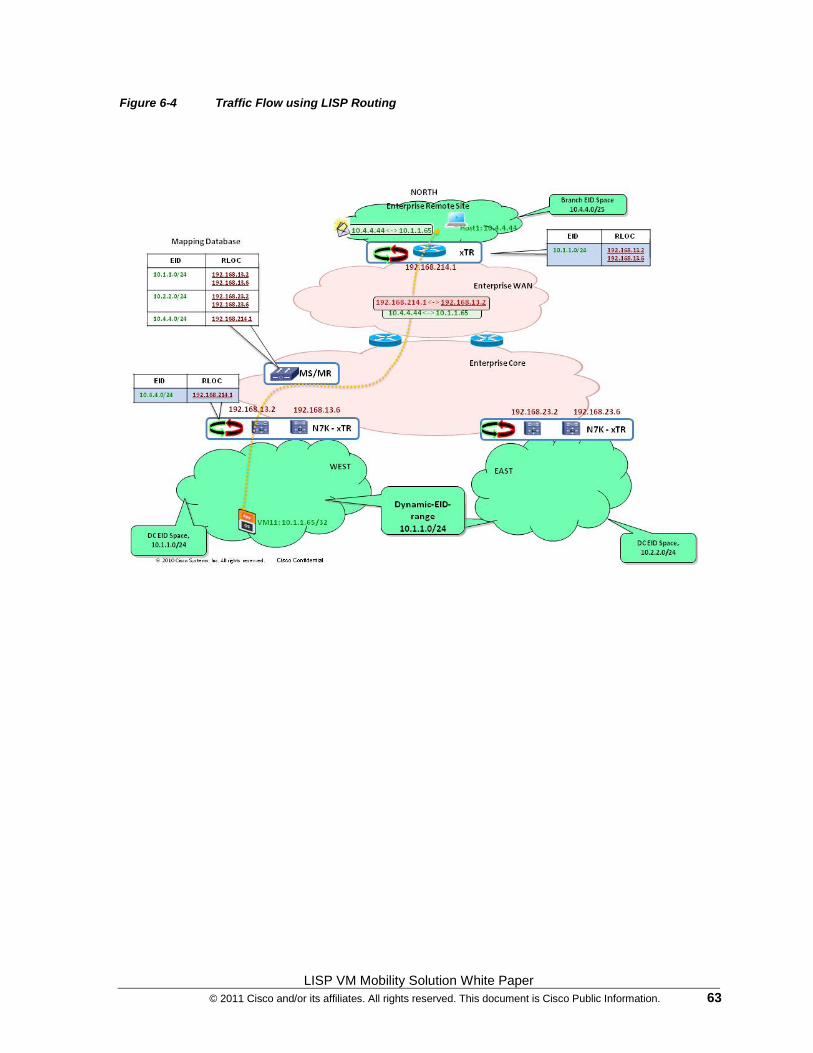
LISP VM Mobility Solution White Paper © 2011 Cisco and/or its affiliates. All rights reserved. This document is Cisco Public Information. 63
Figure 6-4 Traffic Flow using LISP Routing
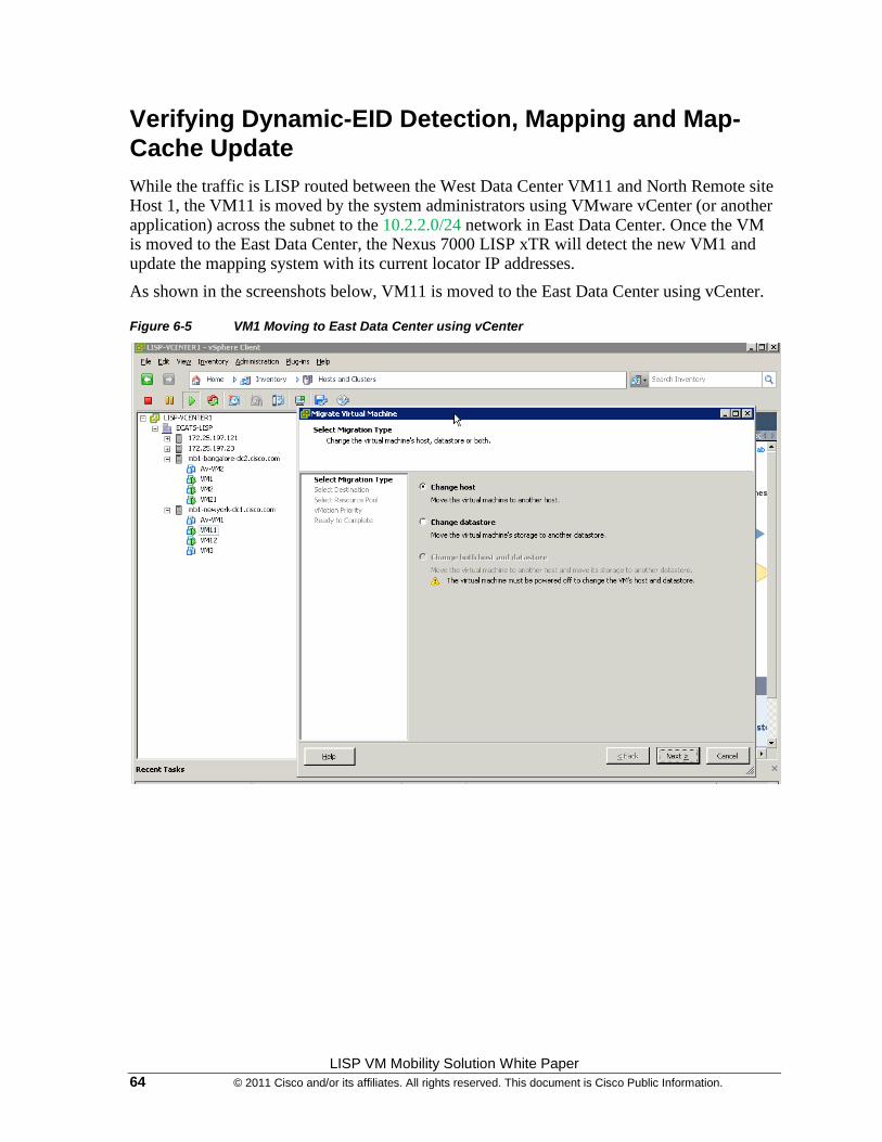
LISP VM Mobility Solution White Paper 64 © 2011 Cisco and/or its affiliates. All rights reserved. This document is Cisco Public Information.
Verifying Dynamic-EID Detection, Mapping and Map-Cache Update While the traffic is LISP routed between the West Data Center VM11 and North Remote site Host 1, the VM11 is moved by the system administrators using VMware vCenter (or another application) across the subnet to the 10.2.2.0/24 network in East Data Center. Once the VM is moved to the East Data Center, the Nexus 7000 LISP xTR will detect the new VM1 and update the mapping system with its current locator IP addresses.
As shown in the screenshots below, VM11 is moved to the East Data Center using vCenter.
Figure 6-5 VM1 Moving to East Data Center using vCenter
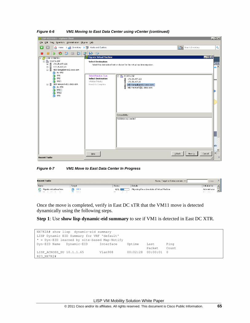
LISP VM Mobility Solution White Paper © 2011 Cisco and/or its affiliates. All rights reserved. This document is Cisco Public Information. 65
Figure 6-6 VM1 Moving to East Data Center using vCenter (continued)
Figure 6-7 VM1 Move to East Data Center In Progress
Once the move is completed, verify in East DC xTR that the VM11 move is detected dynamically using the following steps.
Step 1: Use show lisp dynamic-eid summary to see if VM1 is detected in East DC XTR.
NX7K2A# show lisp dynamic-eid summary LISP Dynamic EID Summary for VRF "default" * = Dyn-EID learned by site-based Map-Notify Dyn-EID Name Dynamic-EID Interface Uptime Last Ping Packet Count LISP_ACROSS_SU 10.1.1.65 Vlan908 00:02:28 00:00:01 0 R23_NX7K2#
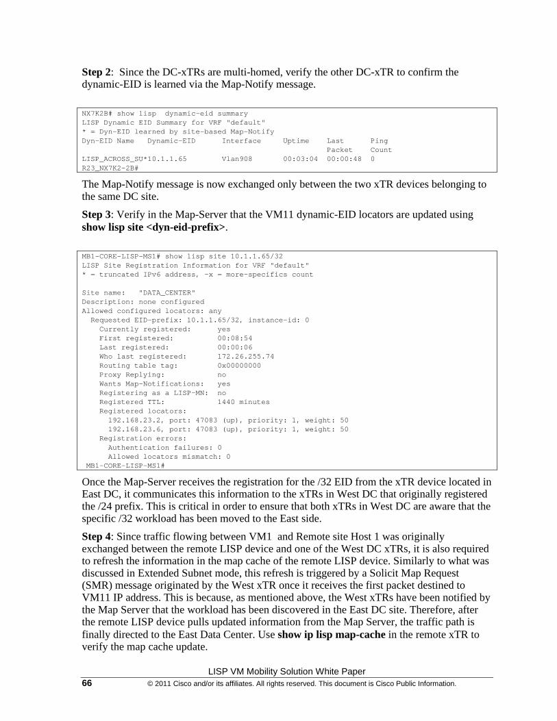
LISP VM Mobility Solution White Paper 66 © 2011 Cisco and/or its affiliates. All rights reserved. This document is Cisco Public Information.
Step 2: Since the DC-xTRs are multi-homed, verify the other DC-xTR to confirm the dynamic-EID is learned via the Map-Notify message.
NX7K2B# show lisp dynamic-eid summary LISP Dynamic EID Summary for VRF "default" * = Dyn-EID learned by site-based Map-Notify Dyn-EID Name Dynamic-EID Interface Uptime Last Ping Packet Count LISP_ACROSS_SU*10.1.1.65 Vlan908 00:03:04 00:00:48 0 R23_NX7K2-2B#
The Map-Notify message is now exchanged only between the two xTR devices belonging to the same DC site.
Step 3: Verify in the Map-Server that the VM11 dynamic-EID locators are updated using show lisp site <dyn-eid-prefix>.
MB1-CORE-LISP-MS1# show lisp site 10.1.1.65/32 LISP Site Registration Information for VRF "default" * = truncated IPv6 address, -x = more-specifics count Site name: "DATA_CENTER" Description: none configured Allowed configured locators: any Requested EID-prefix: 10.1.1.65/32, instance-id: 0 Currently registered: yes First registered: 00:08:54 Last registered: 00:00:06 Who last registered: 172.26.255.74 Routing table tag: 0x00000000 Proxy Replying: no Wants Map-Notifications: yes Registering as a LISP-MN: no Registered TTL: 1440 minutes Registered locators: 192.168.23.2, port: 47083 (up), priority: 1, weight: 50 192.168.23.6, port: 47083 (up), priority: 1, weight: 50 Registration errors: Authentication failures: 0 Allowed locators mismatch: 0 MB1-CORE-LISP-MS1#
Once the Map-Server receives the registration for the /32 EID from the xTR device located in East DC, it communicates this information to the xTRs in West DC that originally registered the /24 prefix. This is critical in order to ensure that both xTRs in West DC are aware that the specific /32 workload has been moved to the East side.
Step 4: Since traffic flowing between VM1 and Remote site Host 1 was originally exchanged between the remote LISP device and one of the West DC xTRs, it is also required to refresh the information in the map cache of the remote LISP device. Similarly to what was discussed in Extended Subnet mode, this refresh is triggered by a Solicit Map Request (SMR) message originated by the West xTR once it receives the first packet destined to VM11 IP address. This is because, as mentioned above, the West xTRs have been notified by the Map Server that the workload has been discovered in the East DC site. Therefore, after the remote LISP device pulls updated information from the Map Server, the traffic path is finally directed to the East Data Center. Use show ip lisp map-cache in the remote xTR to verify the map cache update.
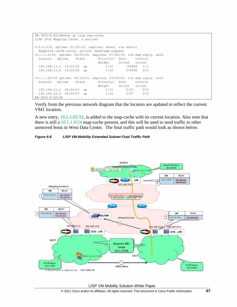
LISP VM Mobility Solution White Paper © 2011 Cisco and/or its affiliates. All rights reserved. This document is Cisco Public Information. 67
BR-3825-E-R214#show ip lisp map-cache LISP IPv4 Mapping Cache, 4 entries 0.0.0.0/0, uptime: 01:34:31, expires: never, via static Negative cache entry, action: send-map-request 10.1.1.0/24, uptime: 16:03:20, expires: 07:56:39, via map-reply, auth Locator Uptime State Priority/ Data Control Weight in/out in/out 192.168.13.2 16:03:20 up 1/10 149838 1/1 192.168.13.6 16:03:20 up 1/10 574546 0/0 10.1.1.65/32 uptime: 00:10:23, expires: 23:55:02, via map-reply, auth Locator Uptime State Priority/ Data Control Weight in/out in/out 192.168.23.2 00:04:57 up 1/10 0/0* 0/0 192.168.23.6 00:04:57 up 1/10 0/0* 0/0 BR-3825-E-R214#
Verify from the previous network diagram that the locators are updated to reflect the current VM1 location.
A new entry, 10.1.1.65/32, is added to the map-cache with its current location. Also note that there is still a 10.1.1.0/24 map-cache present, and this will be used to send traffic to other unmoved hosts in West Data Center. The final traffic path would look as shown below.
Figure 6-8 LISP VM-Mobility Extended Subnet Final Traffic Path
LISP VM Mobility Solution White Paper 68 © 2011 Cisco and/or its affiliates. All rights reserved. This document is Cisco Public Information.
LISP VM Mobility Across Subnet Summary
• LISP VM Mobility across subnet provides automated move detection, map-cache update and provide a direct data Path to the mobile VMs current Location
• Off-Subnet Connections maintained across move
• Preserving on-Subnet connections across move would require to refresh the ARP cache on the moving workload. Because of that, the across subnet deployment model is currently targeted to “cold” workload migration use cases, like for example Disaster Recovery scenarios.
• No routing re-convergence required during move
• No DNS updates required
• Absolutely no host protocol stack changes, OS changes, or configuration changes required
Printed in USA C11-539588-03/28/11


![May the LISP be with You - Nerd2NerdWhy Lisp? More on Macros [ What Lisp?, How Lisp? ]Problems/Features [ When Lisp? ] May the LISP be with You Andrew (kqb) Easton nerd2nerd: nerdend](https://img.pdfslide.us/doc/110x75/5ed9946d1b54311e7967d3e5/may-the-lisp-be-with-you-nerd2nerd-why-lisp-more-on-macros-what-lisp-how.jpg)


![CICADA - USENIX · 1 vm 2 vm 3 vm 4 vm 5vm 6 vm 7 vm 8 vm 9 vm 2 vm 3 vm 4 vm 5 vm 6 vm 7 vm 8 vm 9 vm 1 rigid application (similar to VOC [1]) vm 1 vm 2 vm 3 vm 4 vm 5vm 6 vm 7 vm](https://img.pdfslide.us/doc/110x75/5f3ade2be7477529602b0cb3/cicada-usenix-1-vm-2-vm-3-vm-4-vm-5vm-6-vm-7-vm-8-vm-9-vm-2-vm-3-vm-4-vm-5-vm.jpg)


![LISP-MN - UPC Universitat Politècnica de Catalunyapeople.ac.upc.edu/acabello/PDF/lispmn_tutorial.pdf · Within the LISP architecture [7], LISP-MN [9] speci es the mobility func-tionality,](https://img.pdfslide.us/doc/110x75/5e8400ade93c191f7b31c182/lisp-mn-upc-universitat-politcnica-de-within-the-lisp-architecture-7-lisp-mn.jpg)