Embed Size (px)
Citation preview
UNIVERSITY OF TECHNOLOGY SYDNEY Faculty of Engineering and Information Technology
Location Privacy Protection in Social Networks
by
Mohammad Reza Nosouhi
A Thesis Submitted
in Partial Fulfillment of the
Requirements for the Degree
Doctor of Philosophy
Sydney, Australia
2020

Certificate of Authorship/Originality
I, Mohammad Reza Nosouhi declare that this thesis, is submitted in fulfilment of
the requirements for the award of Doctor of Philosophy, in the School of Computer
Science at the University of Technology Sydney.
This thesis is wholly my own work unless otherwise referenced or acknowledged. In
addition, I certify that all information sources and literature used are indicated in
the thesis.
This document has not been submitted for qualifications at any other academic
institution.
This research is supported by the Australian Government Research Training Pro-
gram.
Signature: Mohammad Reza Nosouhi
Date: 22/07/2020
Production Note:
Signature removed prior to publication.

Acknowledgements
I would like to express my gratitude to my primary supervisor, Professor Shui
Yu, who guided me throughout this research. I appreciate all the time he has spent
on editing my papers, discussing my research ideas, and listening to my problems.
It was a great privilege and honor to work and study under his guidance.
I would also like to give my sincere thanks to Dr Marthie Grobler, my supervisor
in CSIRO’s DATA61 who spent a lot of time on editing my papers and constantly
provided me with advice, help and support.
It is my fortune to gratefully acknowledge the personal and professional support
of my friend and research collaborator, Dr Keshav Sood. I aquired a lot of skills
and experiences from him during my PhD study.
I wish to acknowledge the financial support provided by an Australian Govern-
ment Research Training Program Scholarship (RTPS) and also a CSIRO’s Data61
Top–Up scholarship. This work would not have been possible without their support.
I would also like to express my appreciation to all the staff members of Faculty of En-
gineering and Information Technology and also UTS library, whose services turned
my research a success.
Finally, yet importantly, I would like to thank my parents for their love and
support throughout my life. Most importantly, I wish to thank my loving and
supportive wife, Neda, who provided endless support and inspiration. Without her
encouragement and understanding, this thesis wouldn’t exist.
Mohammad Reza Nosouhi
Sydney, Australia, 2020.
List of Publications
Journal Papers
J-1. MR. Nosouhi, K. Sood, S. Yu, M. Grobler, “PASPORT: A Secure and Private
Location Proof Generation and Verification Framework”, IEEE Transactions
on Computational Social Systems, vol. 7, Issue 2, pp. 293–307, Apr 2020.
Available online at: https://ieeexplore.ieee.org/document/8967030
J-2. MR. Nosouhi, S. Yu, W. Zhou, and M. Grobler, “Blockchain for Secure Lo-
cation Verification”, Journal of Parallel and Distributed Computing, vol. 136,
pp. 40–51, Feb 2020. Available online at: https://www.sciencedirect.
com/science/article/abs/pii/S074373151930320X
J-3 L. Cui, Y. Qu, MR Nosouhi, S. Yu, J.W. Niu, and G. Xie, “Improving Data
Utility Through Game Theory in Personalized Differential Privacy”, Journal
of Computer Science and Technology, vol.34, pp. 272–286, 2019. Available
online at: http://jcst.ict.ac.cn/EN/10.1007/s11390-019-1910-3
Conference Papers
C-1. MR. Nosouhi, S. Yu, K. Sood, and M. Grobler, “HSDC–net: Secure Anony-
mous Messaging in Online Social Networks”, IEEE TrustCom, 2019. Available
online at: https://ieeexplore.ieee.org/document/8887315
C-2. MR. Nosouhi, S. Yu, M. Grobler, Y. Xiang, and Z. Zhu, “SPARSE: Pri-
vacy–Aware and Collusion Resistant Location Proof Generation and Verifica-
tion”, IEEE GLOBECOM, 2018. Available online at: https://ieeexplore.
ieee.org/document/8647933
C-3. MR. Nosouhi, Y. Qu, S. Yu, Y. Xiang, and D. Manuel, “Distance –Based
Location Privacy Protection in Social Networks”, International Telecommu-
v
nications Network and Applications Conference, 2017. Available online at:
https://ieeexplore.ieee.org/document/8215390
C-4. MR. Nosouhi, V. H. Pham, S. Yu, Y. Xiang, and M. Warren, “A Hybrid Lo-
cation Privacy Protection Scheme in Big Data Environment”, IEEE GLOBE-
COM, 2017. Available online at: https://ieeexplore.ieee.org/document/
8254987

Contents
Certificate ii
Acknowledgments iii
List of Publications iv
List of Figures xi
List of Tables xv
Abstract 1
Chapter 1: Introduction 4
1.1 Background . . . . . . . . . . . . . . . . . . . . . . . . . . . . . . . . . 4
1.2 Problem Statement . . . . . . . . . . . . . . . . . . . . . . . . . . . . 7
1.3 Research Questions . . . . . . . . . . . . . . . . . . . . . . . . . . . . 8
1.4 Research Objectives . . . . . . . . . . . . . . . . . . . . . . . . . . . . 9
1.5 Scientific Contributions . . . . . . . . . . . . . . . . . . . . . . . . . . 10
1.6 Thesis Organization . . . . . . . . . . . . . . . . . . . . . . . . . . . . 12
1.7 Conclusion . . . . . . . . . . . . . . . . . . . . . . . . . . . . . . . . . 13
Part I Differential Privacy–Based Approach 15
Chapter 2: Literature Review and Preliminaries 16
2.1 Introduction . . . . . . . . . . . . . . . . . . . . . . . . . . . . . . . . 16
2.2 Literature Review . . . . . . . . . . . . . . . . . . . . . . . . . . . . . 17
2.3 Preliminaries . . . . . . . . . . . . . . . . . . . . . . . . . . . . . . . . 21
vii
2.3.1 Differential Privacy . . . . . . . . . . . . . . . . . . . . . . . . 22
2.3.2 Laplace Mechanism . . . . . . . . . . . . . . . . . . . . . . . . 23
2.4 Conclusion . . . . . . . . . . . . . . . . . . . . . . . . . . . . . . . . . 24
Chapter 3: Customisable Location Privacy Protection in Social
Networks 25
3.1 Introduction . . . . . . . . . . . . . . . . . . . . . . . . . . . . . . . . 25
3.2 Background . . . . . . . . . . . . . . . . . . . . . . . . . . . . . . . . . 26
3.3 The Proposed DBLP2 Mechanism . . . . . . . . . . . . . . . . . . . . 28
3.3.1 System Architecture . . . . . . . . . . . . . . . . . . . . . . . 29
3.3.2 Graph Model . . . . . . . . . . . . . . . . . . . . . . . . . . . 30
3.3.3 Converting Social Distances to Privacy Levels . . . . . . . . . 32
3.3.4 Customisable Differential Privacy . . . . . . . . . . . . . . . . 34
3.4 Conclusion . . . . . . . . . . . . . . . . . . . . . . . . . . . . . . . . . 37
Chapter 4: Results 39
4.1 Introduction . . . . . . . . . . . . . . . . . . . . . . . . . . . . . . . . 39
4.2 System Analysis . . . . . . . . . . . . . . . . . . . . . . . . . . . . . . 39
4.3 Performance Evaluation . . . . . . . . . . . . . . . . . . . . . . . . . . 44
4.4 Conclusion . . . . . . . . . . . . . . . . . . . . . . . . . . . . . . . . . 49
Part II Cryptography–Based Approach 50
Chapter 5: Literature Review and Preliminaries 51
5.1 Introduction . . . . . . . . . . . . . . . . . . . . . . . . . . . . . . . . 51
5.2 Literature Review . . . . . . . . . . . . . . . . . . . . . . . . . . . . . 52
5.2.1 Centralized Schemes . . . . . . . . . . . . . . . . . . . . . . . 52
viii
5.2.2 Distributed Schemes . . . . . . . . . . . . . . . . . . . . . . . 53
5.3 Preliminaries . . . . . . . . . . . . . . . . . . . . . . . . . . . . . . . . 56
5.3.1 Blockchain Overview . . . . . . . . . . . . . . . . . . . . . . . 63
5.3.2 Design Challenges: . . . . . . . . . . . . . . . . . . . . . . . . 64
5.4 Conclusion . . . . . . . . . . . . . . . . . . . . . . . . . . . . . . . . . 68
Chapter 6: PASPORT: Secure and Private Location Proof
Generation and Verification 70
6.1 Introduction . . . . . . . . . . . . . . . . . . . . . . . . . . . . . . . . 70
6.2 Background . . . . . . . . . . . . . . . . . . . . . . . . . . . . . . . . . 72
6.3 PASPORT: The Proposed Scheme . . . . . . . . . . . . . . . . . . . . 75
6.3.1 Architecture and Entities . . . . . . . . . . . . . . . . . . . . . 75
6.3.2 Trust and Threat Model . . . . . . . . . . . . . . . . . . . . . 76
6.3.3 P–TREAD . . . . . . . . . . . . . . . . . . . . . . . . . . . . 77
6.3.4 The Workflow of PASPORT Framework . . . . . . . . . . . . 80
6.3.5 Witness Trust Model . . . . . . . . . . . . . . . . . . . . . . . 84
6.3.6 PASPORT Usability . . . . . . . . . . . . . . . . . . . . . . . 86
6.4 Results . . . . . . . . . . . . . . . . . . . . . . . . . . . . . . . . . . . 87
6.4.1 Security and Privacy Analysis . . . . . . . . . . . . . . . . . . 87
6.4.2 Performance Evaluation . . . . . . . . . . . . . . . . . . . . . 94
6.5 Conclusion . . . . . . . . . . . . . . . . . . . . . . . . . . . . . . . . . 98
Chapter 7: SPARSE: Privacy–Aware and Collusion Resistant
Location Proof Generation and Verification 99
7.1 Introduction . . . . . . . . . . . . . . . . . . . . . . . . . . . . . . . . 99
7.2 The SPARSE Scheme . . . . . . . . . . . . . . . . . . . . . . . . . . . 100
7.3 Results . . . . . . . . . . . . . . . . . . . . . . . . . . . . . . . . . . . 104
ix
7.3.1 Security and Privacy Analysis . . . . . . . . . . . . . . . . . . 104
7.3.2 Performance Evaluation . . . . . . . . . . . . . . . . . . . . . 107
7.4 Conclusion . . . . . . . . . . . . . . . . . . . . . . . . . . . . . . . . . 109
Chapter 8: Blockchain for Secure Location Verification 111
8.1 Introduction . . . . . . . . . . . . . . . . . . . . . . . . . . . . . . . . 111
8.2 The Proposed Architecture . . . . . . . . . . . . . . . . . . . . . . . . 112
8.3 Results . . . . . . . . . . . . . . . . . . . . . . . . . . . . . . . . . . . 119
8.3.1 Security and Privacy Analysis . . . . . . . . . . . . . . . . . . 119
8.3.2 Implementation Results . . . . . . . . . . . . . . . . . . . . . 124
8.4 Conclusion . . . . . . . . . . . . . . . . . . . . . . . . . . . . . . . . . 127
Part III Anonymity–Based Approach 128
Chapter 9: Literature Review and Preliminaries 129
9.1 Introduction . . . . . . . . . . . . . . . . . . . . . . . . . . . . . . . . 129
9.2 Literature Review . . . . . . . . . . . . . . . . . . . . . . . . . . . . . 130
9.3 Preliminaries . . . . . . . . . . . . . . . . . . . . . . . . . . . . . . . . 134
9.3.1 DC–net Overview . . . . . . . . . . . . . . . . . . . . . . . . . 134
9.3.2 DC–net Drawbacks . . . . . . . . . . . . . . . . . . . . . . . . 136
9.3.3 The Short Stability Issue . . . . . . . . . . . . . . . . . . . . . 137
9.4 Conclusion . . . . . . . . . . . . . . . . . . . . . . . . . . . . . . . . . 138
Chapter 10: Anonymity in Social Networks 139
10.1 Introduction . . . . . . . . . . . . . . . . . . . . . . . . . . . . . . . . 139
10.2 HSDC–net: Secure Anonymous Messaging in Online Social Networks . 140
10.2.1 Protocol Description . . . . . . . . . . . . . . . . . . . . . . . 140
x
10.3 Results . . . . . . . . . . . . . . . . . . . . . . . . . . . . . . . . . . . 146
10.3.1 Security Analysis . . . . . . . . . . . . . . . . . . . . . . . . . 147
10.3.2 Performance Evaluation . . . . . . . . . . . . . . . . . . . . . 148
10.4 Conclusion . . . . . . . . . . . . . . . . . . . . . . . . . . . . . . . . . 152
Chapter 11: A Hybrid Location Privacy Protection Scheme in
Big Data Environment 154
11.1 Introduction . . . . . . . . . . . . . . . . . . . . . . . . . . . . . . . . 154
11.2 Background . . . . . . . . . . . . . . . . . . . . . . . . . . . . . . . . . 155
11.3 Assumptions and Definitions . . . . . . . . . . . . . . . . . . . . . . . 157
11.3.1 User’s Location Privacy Requirement . . . . . . . . . . . . . . 158
11.3.2 Analysis of a Correlation–Aware Scheme . . . . . . . . . . . . 159
11.4 The Hybrid Scheme . . . . . . . . . . . . . . . . . . . . . . . . . . . . 160
11.4.1 Direction Filter . . . . . . . . . . . . . . . . . . . . . . . . . . 161
11.4.2 Time Reachability Filter . . . . . . . . . . . . . . . . . . . . . 162
11.4.3 Detached/Hub Filter . . . . . . . . . . . . . . . . . . . . . . . 162
11.5 Analysis on the proposed scheme . . . . . . . . . . . . . . . . . . . . . 163
11.6 Performance Evaluation . . . . . . . . . . . . . . . . . . . . . . . . . . 164
11.6.1 Evaluation Setup . . . . . . . . . . . . . . . . . . . . . . . . . 164
11.6.2 Results . . . . . . . . . . . . . . . . . . . . . . . . . . . . . . . 165
11.7 Conclusion . . . . . . . . . . . . . . . . . . . . . . . . . . . . . . . . . 167
Chapter 12: Summary 168
12.1 Introduction . . . . . . . . . . . . . . . . . . . . . . . . . . . . . . . . 168
12.2 Conclusion . . . . . . . . . . . . . . . . . . . . . . . . . . . . . . . . . 168
Chapter : Bibliography 171

List of Figures
1.1 Research Objectives . . . . . . . . . . . . . . . . . . . . . . . . . . . . 10
2.1 Methods for location privacy protection in location–based services . . . . 19
3.1 The proposed DBLP2 system architecture. . . . . . . . . . . . . . . . . 29
3.2 A simple example showing three users of a social network modelled by a
simple graph. . . . . . . . . . . . . . . . . . . . . . . . . . . . . . . . . 31
3.3 An example of four users with different privacy protection requirements. . 33
4.1 Probability density function for generalised gamma distribution. . . . . . 41
4.2 The magnitude of the injected noise for a (A) conservative user, (B) very
relaxed user, (C) relaxed user, and (D) moderate user. . . . . . . . . . . 45
4.3 The result of a collusion attack in which five users with different social
distances from the victim have shared their response to obtain a more
accurate location data. . . . . . . . . . . . . . . . . . . . . . . . . . . 47
5.1 Distance–bounding protocols are generally exposed to three types of
security attacks: (a) Distance Fraud, (b) Mafia Fraud, and (c) Terrorist
Fraud. . . . . . . . . . . . . . . . . . . . . . . . . . . . . . . . . . . . 58
5.2 Message exchange diagram for TREAD . . . . . . . . . . . . . . . . . . 60
5.3 An example of P–P collusions. . . . . . . . . . . . . . . . . . . . . . . . 65
xii
6.1 The proposed system architecture. . . . . . . . . . . . . . . . . . . . . . 76
6.2 Message flow between the three entities of the proposed scheme. . . . . . 80
6.3 Success probability of a Prover–Witness collusion for different values of
KD and system parameters. . . . . . . . . . . . . . . . . . . . . . . . . 92
6.4 (a) CPU usage for different key sizes. (b) and (c) Time required for LP
generation in our scheme, STAMP [25], and APPLAUS [26] under
different key sizes. In APPLAUS, the authors have not implemented
their scheme for key sizes larger than 256. . . . . . . . . . . . . . . . . . 94
6.5 (a) and (b) Time required for LP generation over different physical
distances. The shown measurements are for the key sizes 2048 for (a) and
256 for (b). (c) P–TREAD distance bounding protocol takes most of the
time required for LP generation. . . . . . . . . . . . . . . . . . . . . . . 95
6.6 Outdoor path for the mobility tests (300 meters). . . . . . . . . . . . . . 97
6.7 Time required for LP generation when multiple witness devices are
involved. (a) outdoor and (b) indoor environments. . . . . . . . . . . . . 98
7.1 The system architecture of SPARSE Scheme . . . . . . . . . . . . . . . . 100
7.2 Message exchange diagram for the proposed scheme. . . . . . . . . . . . . 101
7.3 The success probability of Prover–Witness collusions. (A) β = 40% (B)
β = 60% and (C) β = 80% . . . . . . . . . . . . . . . . . . . . . . . . . 108
7.4 The average number of colluding witnesses that are selected by the
verifier for (A) K = 8 (B) K = 10 and (C) K = 12 . . . . . . . . . . . . 109
8.1 Message exchange diagram of the proposed scheme . . . . . . . . . . . . 113
8.2 In the proposed scheme, each transaction can have different inputs and
outputs. . . . . . . . . . . . . . . . . . . . . . . . . . . . . . . . . . . 113
8.3 Block creation and transaction structure in the proposed scheme. . . . . . 114
xiii
8.4 (a) CPU usage for different key sizes. (b) and (c) Time required for LP
generation in our scheme, STAMP, and APPLAUS under different key
sizes. (d) and (e) Time required for LP generation over different physical
distances. (f) Time required for Tx generation after a witness receives
message m3. . . . . . . . . . . . . . . . . . . . . . . . . . . . . . . . . 125
8.5 The percentage of LP requests that successfully pass the P–P collusion
detection test for different values of T . . . . . . . . . . . . . . . . . . . . 126
9.1 The Dining Cryptographers network in a simple example. . . . . . . . . . 135
10.1 HSDC–net system architecture. . . . . . . . . . . . . . . . . . . . . . . 140
10.2 A simple illustration of SR performance. . . . . . . . . . . . . . . . . . . 143
10.3 Probability of collision after a single run of SR for (a) B = 3 and (b) B = 5.149
10.4 (a) Time required to initialize the protocol, reserve a slot, and perform
one cycle of anonymous message publishing. (b) End–to–end latency to
publish an anonymous post. . . . . . . . . . . . . . . . . . . . . . . . . 150
10.5 Time required to reserve B slots in a single run of SR for different values
of B . . . . . . . . . . . . . . . . . . . . . . . . . . . . . . . . . . . . 151
10.6 End–to–end latency to anonymously publish a tweet for HSDC–net and
some well–known anonymity schemes. . . . . . . . . . . . . . . . . . . . 152
11.1 The concept of Spatiotemporal correlation issue between 2 neighbouring
location sets. . . . . . . . . . . . . . . . . . . . . . . . . . . . . . . . . 157
11.2 Our proposed system architecture. Unlike K–Anonymity methods, there
is no need to have a trusted third–party anonymizer. . . . . . . . . . . . 159
11.3 An example of two neighbour location sets at time Ti−1 and Ti. . . . . . . 159
11.4 Average number of indistinguishable movement paths for 1.5K initial
candidate dummies. . . . . . . . . . . . . . . . . . . . . . . . . . . . . 166

xiv
11.5 Average number of indistinguishable movement paths for 3K initial
candidate dummies. . . . . . . . . . . . . . . . . . . . . . . . . . . . . 166
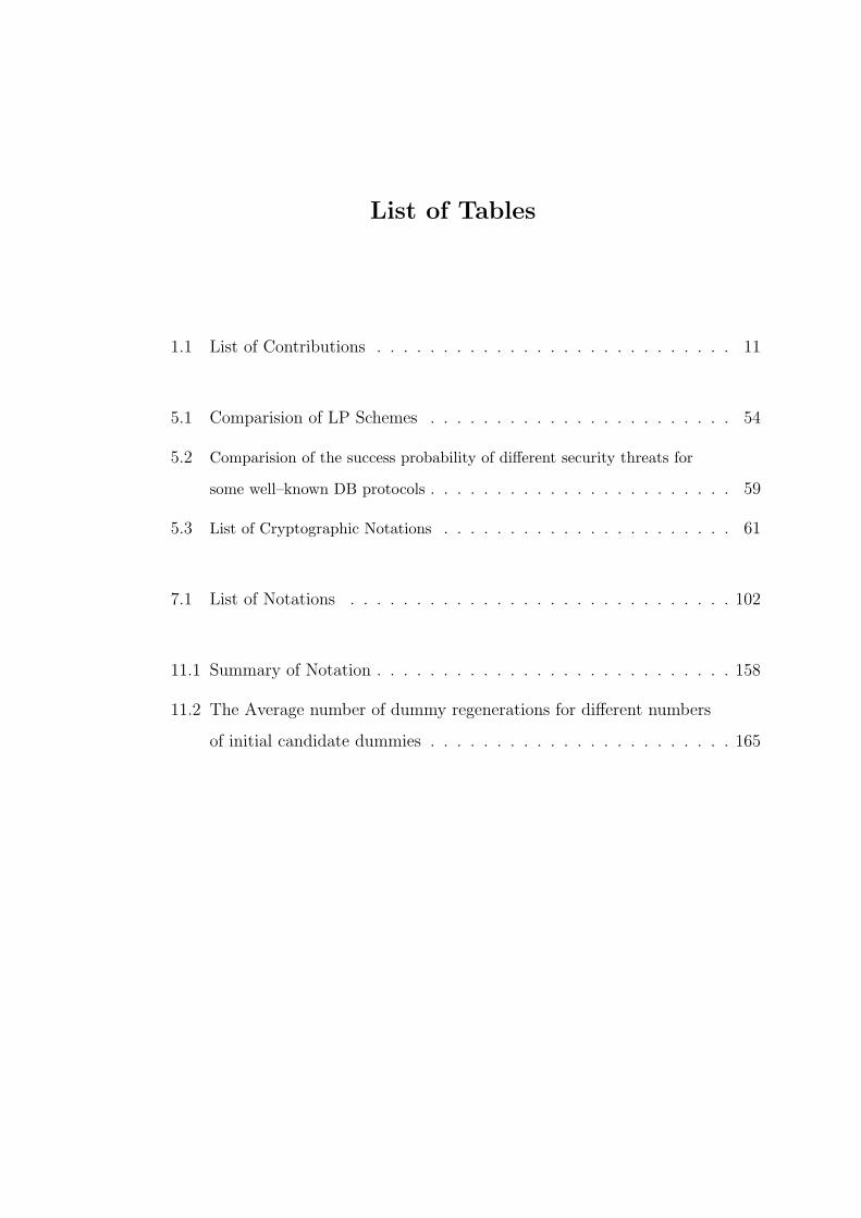
List of Tables
1.1 List of Contributions . . . . . . . . . . . . . . . . . . . . . . . . . . . 11
5.1 Comparision of LP Schemes . . . . . . . . . . . . . . . . . . . . . . . 54
5.2 Comparision of the success probability of different security threats for
some well–known DB protocols . . . . . . . . . . . . . . . . . . . . . . . 59
5.3 List of Cryptographic Notations . . . . . . . . . . . . . . . . . . . . . . 61
7.1 List of Notations . . . . . . . . . . . . . . . . . . . . . . . . . . . . . 102
11.1 Summary of Notation . . . . . . . . . . . . . . . . . . . . . . . . . . . 158
11.2 The Average number of dummy regenerations for different numbers
of initial candidate dummies . . . . . . . . . . . . . . . . . . . . . . . 165
ABSTRACT
Location Privacy Protection in Social Networks
by
Mohammad Reza Nosouhi
Social networks have become more ubiquitous due to new advances in smart-
phone technology. This has provided an opportunity for social network service
providers to utilise location information of users in their services. For example,
Facebook Places, Foursquare and Yelp are popular social networks that mostly rely
on utilising users’ location data in their services. They offer a variety of useful
services, from location recommendations to nearby friend alerts. However, protect-
ing location privacy of users is still an open challenge for social network service
providers. It has been shown that hiding real identity and choosing a pseudonym
does not guarantee to protect a user’s privacy since privacy may be invaded by
analysing position data only. This is really a big issue since other private informa-
tion of users can be revealed by analysing their location data (e.g., home address,
health condition, interests, etc.).
In this study, we investigate the location privacy issue of social networks and pro-
pose several solutions. We classify the proposed solutions into three categories based
on the selected approaches, i.e. (i) differential privacy-based, (ii) cryptography-
based, and (iii) anonymity-based solutions. We first study the approach in which
differential privacy is utilised to preserve privacy of users. In this regard, we develop
Distance–Based Location Privacy Protection mechanism (DBLP2), a customisable
location privacy protection approach that is uniquely designed for social network
users. It utilises the concept of social distance to generalise users’ location data be-
fore it is published in a social network. The level of generalisation is decided based
on the social distance between users.
Secondly, we study cryptography-based methods for location privacy protection
in Location–Based Services (LBS) and social networks. In this domain, we propose
three cryptography-based and privacy–aware location verification schemes to pre-
serve location privacy of users: (i) Privacy–Aware and Secure Proof Of pRoximiTy
(PASPORT), (ii) Secure, Privacy–Aware and collusion Resistant poSition vErifica-
tion (SPARSE), and (iii) a blockchain–based location verification scheme. These
schemes prevent location spoofing attacks conducted by dishonest users while pro-
tect location privacy of users. To the best of our knowledge, majority of the existing
location verification schemes do not preserve location privacy of users.
Thirdly, we investigate anonymity as another approach to preserve users’ pri-
vacy in social networks. In this regard, we first study the relevant protocols and
discuss their features and drawbacks. Then, we introduce Harmonized and Stable
DC–net (HSDC–net), a self–organizing protocol for anonymous communications in
social networks. As far as we know, social networks do not offer any secure anony-
mous communication service. In social networks, privacy of users is preserved using
pseudonymity, i.e., users select a pseudonym for their communications instead of
their real identity. However, it has been shown that pseudonymity does not always
result in anonymity (perfect privacy) if users’ activities in social media are linkable.
This makes users’ privacy vulnerable to deanonymization attacks. Thus, by employ-
ing a secure anonymous communication service, social network service providers will
be able to effectively preserve users’ privacy.
We perform extensive experiments and provide comprehensive security and pri-
vacy analysis to evaluate performance of the proposed schemes and mechanisms.
Regarding the DBLP2 mechanism, our extensive analysis shows that it offers the
optimum data utility regarding the trade–off between privacy protection and data
utility. In addition, our experimental results indicate that DBLP2 is capable of
offering variable location privacy protection and resilience to post processing. For
the SPARSE scheme, our analysis and experiments show that SPARSE provides
privacy protection as well as security properties for users including integrity, un-
forgeability and non–transferability of the location proofs. Moreover, it achieves a
highly reliable performance against collusions. To validate performance of the PAS-
PORT scheme, we implement a prototype of the proposed scheme on the Android
platform. Extensive experiments indicate that the proposed method can efficiently
protect location–based applications against fake submissions. For the proposed
blockchain–based scheme, our prototype implementation on the Android platform
shows that the proposed scheme outperforms other currently deployed location proof
schemes. Finally, our prototype implementation of the HSDC–net protocol shows
that it achieves low latencies that makes it a practical protocol.
In summary, this research study focuses on developing new mechanisms for pre-
serving location privacy of social network users. This is done through different
approaches. Moreover, extensive effort is made to make the current location–related
schemes and protocols privacy–aware. In this regard, several solutions in the form
of scheme, mechanism, and protocol are introduced and their performance is eval-
uated. The results of this research work have also been presented in seven papers
published in peer-revewied journals and conferences.
Keywords: anonymous communications; customizable differential privacy; data
privacy; DC–net; location privacy; location–based services; location proof; social
distance; social networks.
4
Chapter 1
Introduction
1.1 Background
Social networks have become a very popular communication plaftform due to
the various attractive services and facilities that they offer to their users. Since
their introduction in the mid–1990s, social networks such as Facebook, Twitter and
LinkedIn have been exponentially growing every year in terms of active users and
revenue. According to the latest statistics [1], Facebook had 2.41 billion monthly
active users as of the second quarter of 2019 while it had only 100 million in August
2008. Moreover, its revenue has grown from USD 0.4 million in 2004 to USD 17.6
billion in 2019. This rapid and continuous growth of social networks indicates that
they have become a dominant method for people to connect and share information
on the Internet.
Social networks have become more ubiquitous due to new advancements in smart-
phone technology. Consequently, most social media time is now spent on mobile
devices. According to a comScore report, Instagram users spend 98% of their screen
time on their mobile devices rather than on desktops [2]. This figure is 86% for
Twitter users. Thus, an opportunity has been provided for social network service
providers to utilise users’ location information in their services. As a result, new
mobile social networks and Location–Based Services (LBS) have been introduced in
the past few years. For example, Facebook Places, Foursquare and Yelp are popular
social networks that base their services on the users’ location data. They offer useful
services, from location recommendations to nearby friend alerts. In LBS, real–time
5
position data of a mobile user is utilised to provide his/her requested information
such as the nearest ATM, restaurant or a retail store. LBS have become one of the
most attractive mobile applications these days. Based on the market reports, the
number of downloads of LBS apps from different app stores has been more than 7.5
billion downloads in 2019 [3].
However, protecting users’ location privacy is a significant challenge for social
networks. Location privacy is very important because users’ location data can be
used to obtain other private information about them. For example, personal inter-
ests, health status and political tendency may be related to the places visited by a
user. Even if a user’s real name or ID is hidden or pseudonyms are used, it has been
shown that privacy may be invaded by analysing position data only [4], [5]. In this
case the user’s location data can be correlated with public information about the
user to reveal his/her identity. For example, an adversary who has access to users’
spatiotemporal data can reidentify a user if he knows that the user spends time in a
coffee shop every day and uses a specific online service at the same time. In another
example, users’ location data can identify a person as a potential cancer patient
if he/she has frequently visited a medical centre for cancer treatment. Therefore,
using pseudonyms cannot guarantee users’ location privacy by itself [5].
To address this issue, new location privacy preserving mechanisms should be
developed to prevent any undesired publication of users’ spatiotemporal data in
social networks. Although some efforts have been made in these directions, location
privacy is still an open issue in social networks [6], [7]. This study aims to investigate
different approaches for preserving users’ privacy in social networks. We first study
the approach in which Differential Privacy [8], [9] is utilised for privacy protection.
In this regard, we develop Distance–Based Location Privacy Protection mechanism
(DBLP2) which is a customisable location privacy protection mechanism designed
for use in social networks. It utilises the concept of social distance to design a
6
customisable location privacy protection scheme in which a user’s location data is
generalised before it is published in a social network. The level of generalisation is
decided based on the social distance between users. For this reason, we extend the
standard Differential Privacy framework in the proposed mechanism to offer variable
privacy protection.
Secondly, as another approach, we investigate cryptography–based solutions and
methods for location privacy protection in Location–Based Services (LBS) and so-
cial networks. We propose three cryptography–based and privacy–aware location
verification schemes to preserve location privacy of users: (i) Privacy–Aware and
Secure Proof Of pRoximiTy (PASPORT), (ii) Secure, Privacy–Aware and collusion
Resistant poSition vErification (SPARSE), and (iii) a blockchain–based location
verification scheme.
Thirdly, we investigate anonymity as another approach to preserve users’ privacy
in social networks. In this domain, we propose a dummy–based location privacy
protection scheme for LBS [10]. In dummy–based schemes [11–16], in addition to
the user’s real location, some fake location data (dummies) are sent to the Location–
Based Service Provider (LSP) by the user as a service enquiry. This prevents an
adversary who has access to the LSP’s resources from distinguishing the user’s real
location. Furthermore, we introduce Harmonized and Stable DC–net (HSDC–net), a
self–organizing protocol for anonymous communications in social networks. In social
networks, privacy of users is generally preserved using pseudonymity, i.e., users select
a pseudonym for their communications instead of their real identity. However, it
has been shown that pseudonymity does not always result in anonymity (perfect
privacy) if users’ activities in social media are linkable. This makes users’ privacy
vulnerable to deanonymization attacks. Thus, by employing a secure anonymous
communication service, social network service providers will be able to effectively
preserve users’ privacy.
7
1.2 Problem Statement
Recently, due to the advances in the smartphone technology and positioning
systems, there has been the emergence of a variety of location–based applications
and services [17–20] such as activity–tracking applications, location–based services,
database–driven cognitive radio networks (CRNs), and location–based access control
systems. In these applications, mobile users submit their position data to a loca-
tion–based service provider (LBSP) to gain access to a service, resource, or reward.
These applications are very popular due to the useful services they offer. According
to recent business reports, the market value of location–based services (LBS) was
USD 20.53 billion in 2017 and is anticipated to reach USD 133 billion in 2023, with
an expected annual growth rate of 36.55% [21].
However, location privacy is a critical issue for these applications and services.
This is because other private information of users can be revealed by analysing their
location data (e.g., home address, health condition, personal interests, etc.). As
a result, users of location–based social networks are concerned that their location
privacy is breached by service providers or third–party entities. Moreover, when
users share their location data in social networks, they may be uncomfortable be-
cause their location privacy can be breached by other users. This may result in a
large degradation of the network utility because in this case, users may behave more
conservatively and keep their information local.
To address these issues, many research efforts have been made and several solu-
tions proposed so far. However, the existing solutions for privacy protection in social
networks have some critical problems. In this regard, we identified three issues, i.e.
dependency on user collaboration, binary access control, and low efficiency of data
utility that are presented and discussed in the next section. These problems result
in significant privacy concerns for social network users.
8
To summarise, the following is the problem statement of this research work:
To develop new secure and efficient privacy–preserving schemes and mechanisms
for users of location–based social networks through three approaches, i.e. (i) differ-
ential privacy, (ii) cryptography, and (iii) anonymity approaches.
We also investigate the application scenarios of each approach. Different aspects
of the location privacy problem that each approach addresses will also be discussed.
In the next section, we present three research questions that are resulted from the
problem statement of this thesis.
1.3 Research Questions
In this subsection, we present the research questions resulted from the problem
statement.
• Research question (1): Is it possible to develop a privacy–preserving mechanism
that (i) does not rely on users’ collaboration, (ii) is flexible in terms of social
distance between users, and (iii)) achieves an optimum level of data utility?
In this regard, differential privacy [8–9] is a promising tool to address this ques-
tion. It provides a flexible and efficient platform for developing new secure privacy–
preserving mechanisms.
• Research question (2): Can we utilise cryptography–based techniques and solu-
tions to develop a privacy–aware and collusion–resistant location proof scheme
for users of location–based social networks?
In the second part of this research work, we investigate cryptography–based
solutions to protect location–based applications and services [17–20] against location
spoofing attacks while location privacy of users is preserved. In these applications,
9
mobile users submit their position data to a location–based service provider (LBSP)
to gain access to a service, resource, or reward.
• Research question (3): Can we address the existing issues of DC–net and de-
velop a new efficient anonymous communication protocol to provide anonymity
in social networks?
In social networks, lack of anonymous group messaging service is tangible. To the
best of our knowledge, no social network provider offers such a service. Using this
service, users can create groups in social media and anonymously publish their
opinions (see [37–39] for some example applications). To offer anonymity, several
anonymous communication networks (ACNs) have been proposed so far. Among
these protocols, the Dining Cryptographers network (DC–net) [49] is one of the
most popular protocols that guarantees protection against traffic analysis attacks.
However, DC–net suffers from three critical issues that reduces its practicality. This
builds the third part of the research work presented in this thesis.
1.4 Research Objectives
This section presents the targets of this research study. The following three main
objectives are defined for this study.
i. Develop a customisable location privacy protection mechanism based on the
differential privacy framework that is uniquely designed for use in social net-
works.
ii. Develop cryptography–based privacy–preserving location verification mecha-
nisms for location–based social networks.
iii. Design and develop anonymisation schemes for users of social networks based
on the Dining Cryptographers network (DC–net) approach.
10
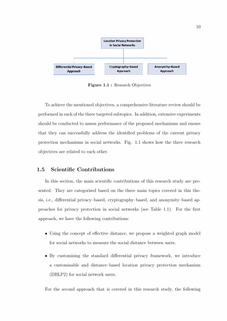
Figure 1.1 : Research Objectives
To achieve the mentioned objectives, a comprehensive literature review should be
performed in each of the three targeted subtopics. In addition, extensive experiments
should be conducted to assess performance of the proposed mechanisms and ensure
that they can successfully address the identified problems of the current privacy
protection mechanisms in social networks. Fig. 1.1 shows how the three research
objectives are related to each other.
1.5 Scientific Contributions
In this section, the main scientific contributions of this research study are pre-
sented. They are categorised based on the three main topics covered in this the-
sis, i.e., differential privacy–based, cryptography–based, and anonymity–based ap-
proaches for privacy protection in social networks (see Table 1.1). For the first
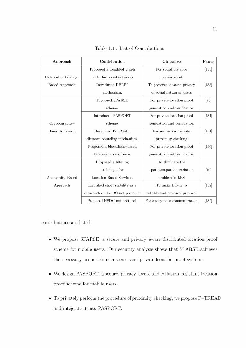
approach, we have the following contributions:
• Using the concept of effective distance, we propose a weighted graph model
for social networks to measure the social distance between users.
• By customising the standard differential privacy framework, we introduce
a customisable and distance–based location privacy protection mechanism
(DBLP2) for social network users.
For the second approach that is covered in this research study, the following
11
Table 1.1 : List of Contributions
Approach Contribution Objective Paper
Proposed a weighted graph For social distance [133]
Differential Privacy– model for social networks. measurement
Based Approach Introduced DBLP2 To preserve location privacy [133]
mechanism. of social networks’ users
Proposed SPARSE For private location proof [93]
scheme. generation and verification
Introduced PASPORT For private location proof [131]
Cryptography– scheme. generation and verification
Based Approach Developed P-TREAD For secure and private [131]
distance bounding mechanism. proximity checking
Proposed a blockchain–based For private location proof [130]
location proof scheme. generation and verification
Proposed a filtering To eliminate the
technique for spatiotemporal correlation [10]
Anonymity–Based Location-Based Services. problem in LBS
Approach Identified short stability as a To make DC-net a [132]
drawback of the DC-net protocol. reliable and practical protocol
Proposed HSDC-net protocol. For anonymous communication [132]
contributions are listed:
• We propose SPARSE, a secure and privacy–aware distributed location proof
scheme for mobile users. Our security analysis shows that SPARSE achieves
the necessary properties of a secure and private location proof system.
• We design PASPORT, a secure, privacy–aware and collusion–resistant location
proof scheme for mobile users.
• To privately perform the procedure of proximity checking, we propose P–TREAD
and integrate it into PASPORT.

12
• We propose a blockchain–based, secure, and privacy–aware scheme for LP
generation and verification in which mobile users generate LPs for each other.
Regarding the last approach, i.e. anonymity in social networks, the contributions of
this research work are as follows:
• A new filtering technique is presented to eliminate the spatiotemporal corre-
lation problem in LBS applications.
• We prove that the “short stability” is a drawback of the DC–net protocol.
• We further improve SDC–net and propose HSDC–net, a collision avoiding and
accountable protocol for anonymous communications.
In the next section, we present the structural organization of the thesis.
1.6 Thesis Organization
This thesis is organised as follows:
• Part I: We investigate the differential privacy–based approach in Part I. We
first present a comprehensive literature review and some preliminaries in Chap-
ter 2. Efforts have been made to identify and present the related research issues
and directions. In Chapter 3, the research methodology for Customisable Lo-
cation Privacy Protection in Social Networks is presented. The results of our
analysis and experiments are presented and discussed in Chapter 4.
• Part II: In the second part of the thesis, we investigate the cryptography–
based approach and propose some privacy–preserving schemes based on cryp-
tographic algorithms and techniques. We first present the relevant literature
review and some preliminaries in Capter 5. Then, in Chapter 6, we introduce
Privacy–Aware and Secure Proof Of pRoximiTy (PASPORT) and present the
13
results of our analysis and experiments. Our second proposed scheme, i.e. Se-
cure, Privacy–Aware and collusion Resistant poSition vErification (SPARSE),
is introduced in Chapter 7. Finally, in Chapter 8, we introduce the blockchain–
based location verification scheme and present the results of our experiments.
• Part III: In the last part of the thesis, we investigate the anonymity–based
approach and introduce two solutions for privacy protection. Firstly, in Chap-
ter 9, we present some related work and preliminaries. Then, in Chapter
10, our first anonomity–based solution, i.e. Harmonized and Stable DC–net
(HSDC–net), is introduced. Finally, in Chapter 11, our second anonomity–
based solution is introduced and its performance is evaluated and discussed.
• Chapter 12: This chapter summarises the thesis and highlights key investiga-
tions.
1.7 Conclusion
Social networks have recently become one of the most popular platforms for
communications. They have been exponentially growing every year in terms of active
users and revenue. Moreover, the recent advances in the smartphone technology and
positioning systems have made social networks more ubiquitous. This has resulted
in the emergence of a variety of location–based applications and services. In these
applications, mobile users submit their position data to a location–based service
provider (LBSP) to gain access to a service, resource, or reward. However, preserving
users’ location privacy is still a big challenge for social networks due to the recent
development of the data analysis and mining technologies. Location privacy is very
important for users because other private information about users can be obtained
by knowing their location data.
In the next chapter, we present an extensive literature review about the research

14
questions addressed in this thesis. We first review the research studies relevant
to customisable location privacy in social networks. Then, we present a literature
review of the anonymity issue in social networks. Finally, we explore the location
verification schemes in location–based social networks by giving an overview of the
existing location proof schemes and discussing their pros and cons.
15
Part I
Differential Privacy–Based
Approach
16
Chapter 2
Literature Review and Preliminaries
2.1 Introduction
The recent advances in smartphone technology and positioning systems has en-
abled social network service providers to offer a variety of location–based applica-
tions and services for their users. In these applications, real–time location data of
mobile users is utilised to provide requested information or access to a resource or
service. The variety of useful services offered by these applications has made them
very popular [14], [17–19]. However, preserving location privacy of users is a big
challenge for the service providers since users share their location data either with
other users or with a service provider.
This chapter presents a literature review on the current privacy preserving tech-
niques and solutions in social networks. This includes the privacy preserving mecha-
nisms proposed based on the popular differential privacy framework. We also discuss
the current location privacy preservation mechanisms proposed for Location–Base
Services (LBS) and Geo–Social Networks (GeoSNs). In this regard, K–Anonymity,
Dummy–Based, and Cryptography–Based schemes are reviewed.
Moreover, this chapter presents some preliminaries as the foundation for the next
chapter. After briefly reviewing the concept of differential privacy and the Laplace
mechanism, we introduce the necessity of customising the adjacency relation defined
in the standard differential privacy to match its definition with the location domain.
17
2.2 Literature Review
Privacy protection in social networks has been comprehensively studied by Abawajy
et al. [59] to present a comprehensive survey of the recent developments in social
networks’ data publishing. They have analysed different privacy risks and attacks in
social media along with the presentation of a threat model. They have also quanti-
fied and classified the background knowledge which is used by adversaries to violate
users’ privacy. In addition, Fire et al. [60] presented some strategies and methods in
privacy preserving social network data publishing through a detailed review of differ-
ent security and privacy issues. They have reviewed a range of existing solutions for
these privacy issues along with eight simple–to–implement recommendations which
can improve users’ security and privacy when using these platforms [13].
A few location privacy protection mechanisms have been proposed based on
differential privacy. In [64], a perturbation technique based on differential privacy
was introduced to achieve geo–indistinguishability for protecting the exact location
of a user. This technique adds random Laplace–distributed noise to users’ location in
order to sanitize their location before publishing. A differentially private hierarchical
location sanitization (DPHLS) approach has been proposed for location privacy
protection in large–scale user trajectories. The approach provides a personalised
hierarchical mechanism that protects a user’s location privacy by hiding the location
in a dataset that includes a subset of all possible locations that might be visited in a
region [65]. By doing this, the level of location randomisation is reduced, hence, the
amount of noise required for satisfying differential privacy conditions is minimized.
Another research study in the differential privacy field has been conducted in [66]
to consider the problem of releasing private data under differential privacy when the
privacy level is subject to change over time. In spite of other works that consider
privacy level as a fixed value, they have studied cases in which users may wish
18
to relax their privacy level for subsequent releases of the same data after either
a re–evaluation of the privacy concerns or the need for better accuracy. For this
reason, the authors have presented a mechanism whose outputs can be described by
a lazy Markov stochastic process to analyse the case of gradual release of private
data.
Some other research studies have recently been done on the location privacy
of Geo–Social Networks (GeoSNs) users [61], [67–69]. GeoSNs are a variety of so-
cial networks by which users can find their favourite events, persons or groups in
a specific region or identify popular places by comparing how many people have
already checked–in at different places. This is done by utilising users’ location data
which have been shared by them in that region. In fact, GeoSNs combine location
recommendation services (such as services offered by location–based services) with
social network functionality [10], [69]. In other words, they can be viewed as loca-
tion–based social networks which connect people in a specific region based on their
interests.
In [69] different GeoSNs were classified into three categories Content–Centric,
Check–In Based and Tracking–Based according to the services they offer. In ad-
dition, the main privacy issues that threaten user location privacy were identified.
Moreover, the authors of [67] have studied techniques that sanitize users’ location
data based on differential privacy framework before publishing them as location
recommendations in GeoSNs. Moreover, to enhance the accuracy of the location
recommendations, they have identified some effective factors which improve data
accuracy.
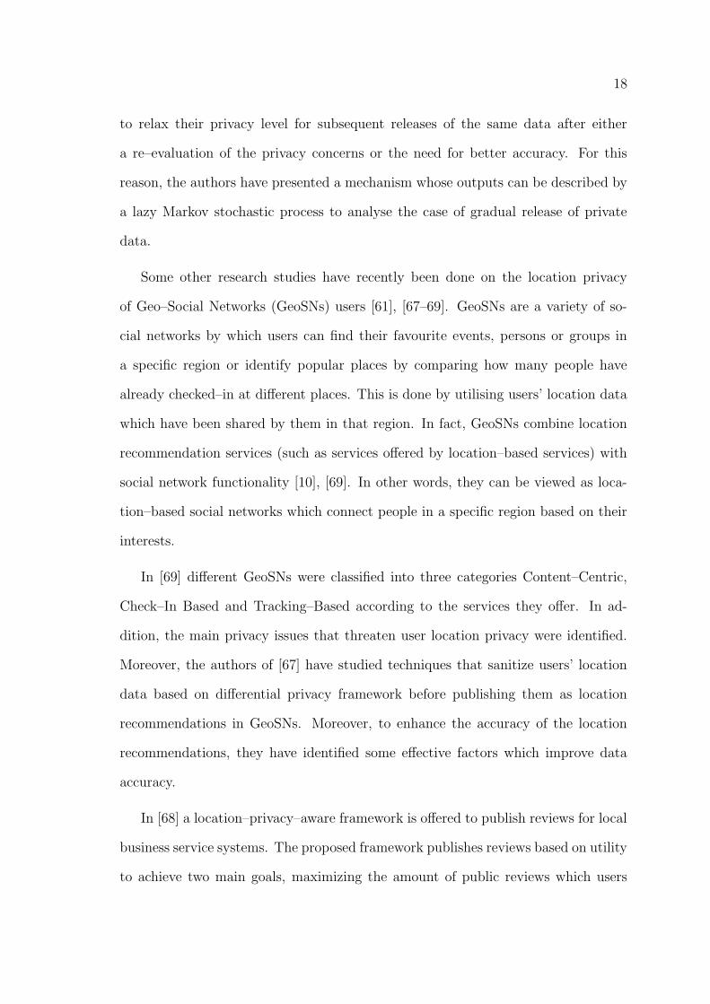
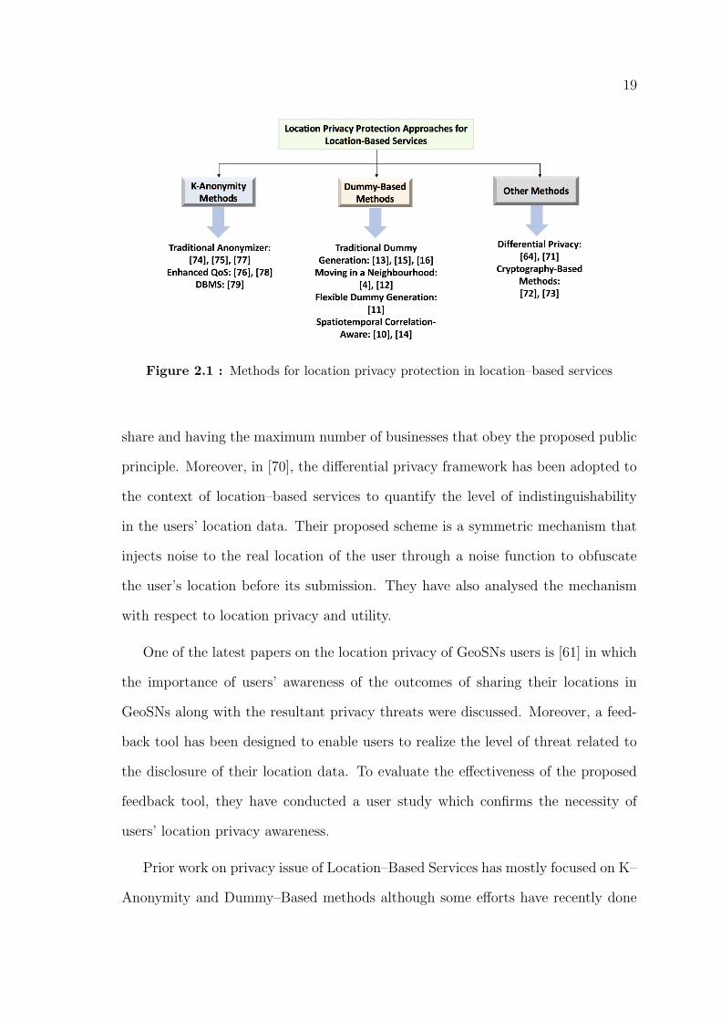
In [68] a location–privacy–aware framework is offered to publish reviews for local
business service systems. The proposed framework publishes reviews based on utility
to achieve two main goals, maximizing the amount of public reviews which users
19
Figure 2.1 : Methods for location privacy protection in location–based services
share and having the maximum number of businesses that obey the proposed public
principle. Moreover, in [70], the differential privacy framework has been adopted to
the context of location–based services to quantify the level of indistinguishability
in the users’ location data. Their proposed scheme is a symmetric mechanism that
injects noise to the real location of the user through a noise function to obfuscate
the user’s location before its submission. They have also analysed the mechanism
with respect to location privacy and utility.
One of the latest papers on the location privacy of GeoSNs users is [61] in which
the importance of users’ awareness of the outcomes of sharing their locations in
GeoSNs along with the resultant privacy threats were discussed. Moreover, a feed-
back tool has been designed to enable users to realize the level of threat related to
the disclosure of their location data. To evaluate the effectiveness of the proposed
feedback tool, they have conducted a user study which confirms the necessity of
users’ location privacy awareness.
Prior work on privacy issue of Location–Based Services has mostly focused on K–
Anonymity and Dummy–Based methods although some efforts have recently done
20
on other techniques such as Differential Privacy [64], [71] and Cryptography–Based
[72–73] schemes.
K–Anonymity efforts [74–78] require a trusted third–party server which is called
an anonymizer, between users and LSP. The anonymizer receives service requests
from a user and enlarges its location into a region (cloaking region) so that it con-
tains the locations of K − 1 other users as well as location of the requesting user.
Therefore, the adversary cannot identify the requesting user among other K − 1
users. The advantage of these methods is that the communication cost between
users and anonymizer is reduced, however, they suffer from decreased QoS because
when there are not enough users near the requested user, the anonymizer has to in-
crease the radius of cloaking region, hence, the increased processing times results in
a greater service latency. To solve this problem, some efforts have been done in [76]
and [78] to increase QoS. In these papers the area of cloaking region is minimized
by using footprints–historical locations of other users.
Although the mentioned efforts have solved the low QoS problem, they still rely
on a trusted third–party anonymizer which is a disadvantage for these schemes. To
address this issue, a K–Anonymity privacy protection scheme has been proposed in
[79] which does not rely on a trusted anonymizer between users and LSP. However,
this method still requires a DataBase Management System (DBMS) to operate.
Several dummy–based location privacy schemes [4], [12–16] have been proposed
so far for location privacy protection. In all of them users send their location data
including noise (some fake location data or dummies) to LSP directly. Thus, there
is no need for a trusted anonymizer. In [4] and [12], two dummy generation algo-
rithms have been presented, Moving in a Neighbourhood and Moving in a Limited
Neighbourhood. In these algorithms, the first dummy set is selected randomly but
next dummies are generated in a neighbourhood of the previous position of the
21
dummies. Moreover, a cost reduction technique was proposed in [4] to limit the
communications overhead caused by sending dummies.
However, generating dummies at random or through a fixed rule can not provide
flexible location privacy for users. Hence, in [11], a Privacy–Area Aware scheme
is proposed based on a flexible dummy generation algorithm in which dummies
are generated according to either a virtual grid or circle. This approach provides
configurable and controllable dummy generation by which it is possible to control the
user’s location privacy. A disadvantage of this method is that it does not consider
nature of the region. For example, some dummies may be generated in an unlikely
location for a user (e.g., in a river). To solve this problem in [12] a Dummy–Location
Selection (DLS) method has been proposed to prevent the adversary from exploiting
side information such as a region map. This is done by carefully selecting dummies
based on the entropy metric.
However, in [14] it has been showed that when a user adopts one of the afore-
mentioned dummy–based methods, the adversary can identify some dummies with
a minimum correct ratio of 58% by means of the spatiotemporal correlation be-
tween neighbouring location sets. Therefore, they have proposed a Spatiotemporal
Correlation–Aware privacy protection scheme in which correlated dummies are fil-
tered out and only uncorrelated dummies are sent to LSP. However, this method
can protect user’s location privacy under some conditions only and if the adversary
estimates the threshold angle which is used to filter space correlated dummies, he
will be able to identify dummies or even the user’s real location.
2.3 Preliminaries
This section presents some preliminaries that is required as the foundation for
the next chapter. We first review the concept of differential privacy and the Laplace
mechanism. Then, we discuss the necessity of customising the adjacency relation
22
defined in the standard differential privacy to match its definition with the location
domain.
2.3.1 Differential Privacy
Differential privacy [8] is a privacy preserving framework that enables data
analysing bodies to promise privacy guarantees to individuals who share their per-
sonal information. In fact, differentially private mechanisms can make users’ private
data available for data analysis, without needing data clean rooms, data usage agree-
ments or data protection plans [9]. More precisely, a differentially private mechanism
that publishes users’ private data provides a form of indistinguishability between ev-
ery two adjacent databases. Here, ”adjacent” means that they differ only in a single
record. However, as you see later, we will extend the concept of ”adjacency” to the
location domain.
Definition [8]: The randomised mechanism A with domain H is ε−differential
private if for all S ⊆ Range(A) and for all adjacent x, y ∈ H (i.e. ||x− y||1 ≤ 1) we
have
Pr[A(x) ⊆ S] ≤ eεPr[A(y) ⊆ S],
where ε is the privacy level which is a positive value and denotes the level of privacy
guarantees such that a smaller value of ε represents a stricter privacy requirement.
In other words, for a smaller ε, the mechanism makes any adjacent data x and y
more indistinguishable, i.e. for a small value of ε, with almost the same probability,
the published A(x) and A(y) are placed in the same region S. However, for a
large ε, this probability is much higher for A(x) than A(y) which makes them
more distinguishable. Therefore, mechanism A can address privacy concerns that
individuals might have about the release of their private information. Note that
differential privacy is a definition, not an algorithm [9]. In other words, we can have
many differentially private algorithms for a privacy scenario and a given ε.
23
2.3.2 Laplace Mechanism
One of the most popular mechanisms developed based on the differential privacy
framework is the Laplace mechanism [9], [64], [97] in which Laplace–distributed
noise is added to users’ private data to make it ε−differentially private.
Laplace Mechanism [9]: Given the private data x ∈ H, the Laplace mechanism
is defined as:
AL(x, ε) = x+N,
where, N is Laplace–distributed noise with scale parameter 1/ε and zero mean, i.e.,
N ∼ Lap(0,1
ε)
The probability density function for N is:
fN(n) =ε
2e(−ε|n|), (2.1)
where ε denotes the privacy level required by the user. The Laplace distribution
is a symmetric version of the exponential distribution. According to its probabil-
ity density function, with high probability, the Laplace mechanism generates much
stronger noise for small values of privacy level and vice versa [9], [64], [97].
In this research work, we consider the set of private data H ⊆ R2 since our target
is to protect users’ location data which is assumed as L =< latitude, longitude >
where latitude, longitude ∈ R are GPS coordinates in the ranges [−90, 90] and
[−180, 180] respectively. Moreover, the adjacency relation defined in the standard
differential privacy should be customised, since we need a mechanism for publishing
location data which guarantees that adjacent locations are indistinguishable to some
extent. For this reason, we will customise the adjacency relation definition later in
the next section in order to use differential privacy framework in location domain.
24
2.4 Conclusion
In this chapter, we reviewed the existing literature on the current privacy pre-
serving techniques and solutions in social networks and reviewed the advantages and
disadvantages of each solution. It is concluded that differential privacy, as a promis-
ing framework, can be employed to develop reliable and efficient privacy preserving
mechanisms in social networks.
Moreover, this chapter presented some preliminaries as the foundation for the
next chapter. In this regard, the concept of differential privacy and the Laplace
mechanisms were presented. Moreover, we discussed the necessity of customising the
adjacency relation defined in the standard differential privacy to match its definition
with the location domain.
In the next chapter, we introduce the Distance–Based Location Privacy Pro-
tection (DBLP2) mechanism for users of social networks. It provides customisable
location privacy protection by which social network users can customise their privacy
settings according to their social distance to other users.
25
Chapter 3
Customisable Location Privacy Protection in
Social Networks
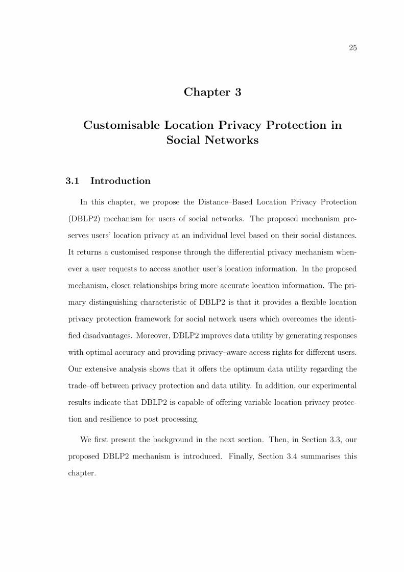
3.1 Introduction
In this chapter, we propose the Distance–Based Location Privacy Protection
(DBLP2) mechanism for users of social networks. The proposed mechanism pre-
serves users’ location privacy at an individual level based on their social distances.
It returns a customised response through the differential privacy mechanism when-
ever a user requests to access another user’s location information. In the proposed
mechanism, closer relationships bring more accurate location information. The pri-
mary distinguishing characteristic of DBLP2 is that it provides a flexible location
privacy protection framework for social network users which overcomes the identi-
fied disadvantages. Moreover, DBLP2 improves data utility by generating responses
with optimal accuracy and providing privacy–aware access rights for different users.
Our extensive analysis shows that it offers the optimum data utility regarding the
trade–off between privacy protection and data utility. In addition, our experimental
results indicate that DBLP2 is capable of offering variable location privacy protec-
tion and resilience to post processing.
We first present the background in the next section. Then, in Section 3.3, our
proposed DBLP2 mechanism is introduced. Finally, Section 3.4 summarises this
chapter.
26
3.2 Background
Social networks have recently become a popular online communication platform.
According to the latest statistics [1], Facebook had more than 2.41 billion monthly
active users in 2019 while it had only 100 million in 2008. This rapid and continuous
growth of social networks indicates that communication on them has become a
prominent method for people to connect and share information on the Internet.
Furthermore, people even use these services for their business promotion, such as
advertising and marketing activities. Furthermore, social networks have become
more ubiquitous due to the new advances in smartphone technology [6], [7]. This
has provided an opportunity for social network service providers to utilise location
information of users in their services. For example, Facebook Places, Foursquare and
Yelp are popular social networks that mostly rely on utilising users’ location data in
their services. They offer a variety of useful services, from location recommendation
to nearby friend alerts.
However, a big challenge for social networks is how to protect location privacy of
users. This challenge has become one of the most important issues in social media
due to the existing structure of social networks that enables an adversary to track
movements of users [6], [7]. For example, a new Chrome extension called Marauder’s
Map has been developed that enables Facebook users to easily track movements
of other users and plot them on a map with an accuracy of around one meter
[55]. It uses the location data that users have shared in Facebook Messenger chats.
Moreover, different methods have been proposed for user location inference based
on users’ tweets [56–58]. This is a significant issue since other private information
of users can be revealed by analysing their location data (e.g., home address, health
condition, interests, etc.).
To address these privacy issues, social network service providers offer some built–
27
in tools enabling users to decide on their own privacy preferences. In addition,
different methods have been proposed to protect user location privacy in social
networks and Geo–Social Networks (GeoSNs) [61], [65], [67], [68]. However, these
tools and methods introduce additional problems that may lead to further privacy
leakage as follows.
Firstly, current solutions rely on user collaboration while some users may not be
competent enough to collaborate in such processes. Moreover, some users are not
even aware that social networks have been equipped with these privacy protection
tools. They might customise their default privacy settings only after their privacy
is violated [59], [60]. Secondly, the mentioned privacy protection tools and methods
are not efficient enough to protect different users’ privacy requirements [60], [61].
Specifically, they are not flexible in terms of social distance between users and rigidly
divide users to be either friends or strangers [62]. These privacy protection tools
look at the level of privacy protection as a rigid binary function, while in reality, we
treat privacy differently against different relationships. Although differential privacy
[8], [9] is the dominant tool used for privacy protection, it cannot offer customised
privacy protection in its current form. Finally, applying rigid privacy policies keeps
users information local and limits data utility for public [62], [106].
To address the aforementioned problems, in the next subsection, we propose the
Distance–Based Location Privacy Protection (DBLP2) mechanism. The proposed
mechanism protects location privacy of social network users based on their social
distances. We define social distance as a measurement index of social relationship
which indicates the intimacy of users based on their interactions in the social net-
work. In the next section, we present the preliminary knowledge of the related
topics.
28
3.3 The Proposed DBLP2 Mechanism
In this section, the proposed DBLP2 mechanism is presented. Firstly, we present
the system architecture and propose a graph model for social networks. Then, we
discuss how social distances are converted to privacy levels. Finally, we present the
proposed customisable differential privacy framework. The designed mechanism is
independent of user collaboration and improves the utility of social networks. In
other words, it satisfies the following properties:
Flexible privacy : The system must generate ε(dij)–differential private responses,
where dij is the social distance between user ui and uj. Thus, the privacy level ε
must be a function of social distances.
Independent of user collaboration: The system must embrace the whole respon-
sibility of users’ privacy protection regardless of whether users collaborate with the
system or not. Therefore, by default, the system must perform a standard distance–
to–privacy function for each user to obtain the required privacy levels against other
users. Competent users can customise this function based on their own requirements.
Optimal accuracy : Responses generated by the system must be as accurate
as possible regarding the trade–off between privacy protection and data utility.
Therefore, to preserve data utility, the level of location generalisation must be
kept to a minimum, i.e., the system needs to minimise the expected squared er-
ror ‖ Lij − Li ‖2 (i, j ∈ V ), where Li is the real location of user ui and Lij is an
approximation of Li generated by the system for sending to user uj.
In the next section, we present system architecture of the proposed DBLP2
mechanism.
29
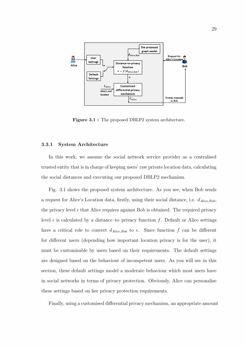
Figure 3.1 : The proposed DBLP2 system architecture.
3.3.1 System Architecture
In this work, we assume the social network service provider as a centralised
trusted entity that is in charge of keeping users’ raw private location data, calculating
the social distances and executing our proposed DBLP2 mechanism.
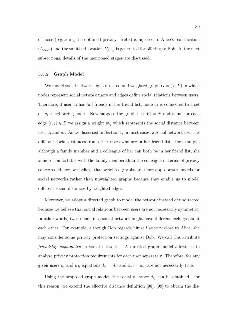
Fig. 3.1 shows the proposed system architecture. As you see, when Bob sends
a request for Alice’s Location data, firstly, using their social distance, i.e. dAlice,Bob,
the privacy level ε that Alice requires against Bob is obtained. The required privacy
level ε is calculated by a distance–to–privacy function f . Default or Alice settings
have a critical role to convert dAlice,Bob to ε. Since function f can be different
for different users (depending how important location privacy is for the user), it
must be customisable by users based on their requirements. The default settings
are designed based on the behaviour of incompetent users. As you will see in this
section, these default settings model a moderate behaviour which most users have
in social networks in terms of privacy protection. Obviously, Alice can personalise
these settings based on her privacy protection requirements.
Finally, using a customised differential privacy mechanism, an appropriate amount
30
of noise (regarding the obtained privacy level ε) is injected to Alice’s real location
(LAlice) and the sanitised location L′Alice is generated for offering to Bob. In the next
subsections, details of the mentioned stages are discussed.
3.3.2 Graph Model
We model social networks by a directed and weighted graph G = (V,E) in which
nodes represent social network users and edges define social relations between users.
Therefore, if user ui has |ui| friends in her friend list, node ui is connected to a set
of |ui| neighboring nodes. Now suppose the graph has |V | = N nodes and for each
edge (i, j) ∈ E we assign a weight wij which represents the social distance between
user ui and uj. As we discussed in Section 1, in most cases, a social network user has
different social distances from other users who are in her friend list. For example,
although a family member and a colleague of her can both be in her friend list, she
is more comfortable with the family member than the colleague in terms of privacy
concerns. Hence, we believe that weighted graphs are more appropriate models for
social networks rather than unweighted graphs because they enable us to model
different social distances by weighted edges.
Moreover, we adopt a directed graph to model the network instead of undirected
because we believe that social relations between users are not necessarily symmetric.
In other words, two friends in a social network might have different feelings about
each other. For example, although Bob regards himself as very close to Alice, she
may consider some privacy protection settings against Bob. We call this attribute
friendship asymmetry in social networks. A directed graph model allows us to
analyze privacy protection requirements for each user separately. Therefore, for any
given users ui and uj, equations dij = dji and wij = wji are not necessarily true.
Using the proposed graph model, the social distance dij can be obtained. For
this reason, we extend the effective distance definition [98], [99] to obtain the dis-
31
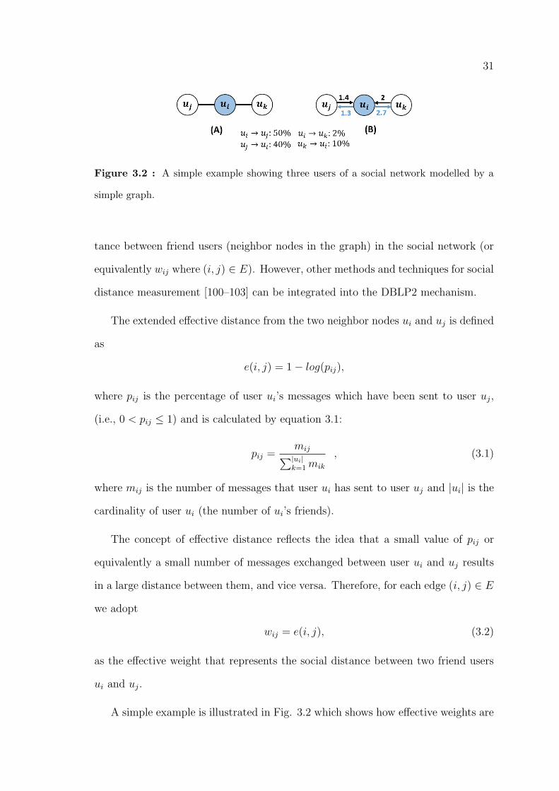
Figure 3.2 : A simple example showing three users of a social network modelled by a
simple graph.
tance between friend users (neighbor nodes in the graph) in the social network (or
equivalently wij where (i, j) ∈ E). However, other methods and techniques for social
distance measurement [100–103] can be integrated into the DBLP2 mechanism.
The extended effective distance from the two neighbor nodes ui and uj is defined
as
e(i, j) = 1− log(pij),
where pij is the percentage of user ui’s messages which have been sent to user uj,
(i.e., 0 < pij ≤ 1) and is calculated by equation 3.1:
pij =mij∑|ui|k=1 mik
, (3.1)
where mij is the number of messages that user ui has sent to user uj and |ui| is the
cardinality of user ui (the number of ui’s friends).
The concept of effective distance reflects the idea that a small value of pij or
equivalently a small number of messages exchanged between user ui and uj results
in a large distance between them, and vice versa. Therefore, for each edge (i, j) ∈ E
we adopt
wij = e(i, j), (3.2)
as the effective weight that represents the social distance between two friend users
ui and uj.
A simple example is illustrated in Fig. 3.2 which shows how effective weights are
32
applied to the nodes of a social network graph. As you see, 50% of user ui’s messages
has been sent to uj (i.e., Pij = 0.5) while she has sent only 2% of her messages to
uk. Therefore, after calculating effective weights for each friend using equation 3.2
and applying them to the graph, Fig. 3.2(B) is obtained. You see that ui has a
smaller distance to uj (1.3) than uk (2.7). The friendship asymmetry attribute is
also considered in our model (Fig. 3.2(B)) which makes the social network graph a
directed graph.
By applying effective weights to the whole network’s graph, we are able to cal-
culate the distance between non–friend users. For this reason, we just need to add
individual effective weights on each path between two non–neighbor nodes and find
the path with the minimum additive effective weights, i.e.
dij = min(
Kp∑l=1
wpl ) ,
where wpl is the effective weight of the lth edge on the pth path between node ui
and uj and Kp is the the number of edges that make path p.
Different methods have been proposed to find the shortest path between a pair
of nodes in graphs [100–103]. Since the purpose of this section is not to offer an
algorithm for the shortest path problem, we just assume that we have the distance
between any pairs of nodes in the network.
3.3.3 Converting Social Distances to Privacy Levels
Before injecting noise to a user’s location data, we need to quantify her privacy
level against other users in a social network since we need to design a system with
flexible (variable) privacy level. Hence, we adopt the social distance as a determinant
factor to obtain different privacy levels that a user requires against other users.
To discuss how social distances are mapped to privacy levels, we assume f is a
33
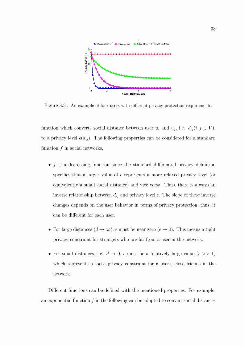
Figure 3.3 : An example of four users with different privacy protection requirements.
function which converts social distance between user ui and uj, i.e. dij(i, j ∈ V ),
to a privacy level ε(dij). The following properties can be considered for a standard
function f in social networks.
• f is a decreasing function since the standard differential privacy definition
specifies that a larger value of ε represents a more relaxed privacy level (or
equivalently a small social distance) and vice versa. Thus, there is always an
inverse relationship between dij and privacy level ε. The slope of these inverse
changes depends on the user behavior in terms of privacy protection, thus, it
can be different for each user.
• For large distances (d→∞), ε must be near zero (ε→ 0). This means a tight
privacy constraint for strangers who are far from a user in the network.
• For small distances, i.e. d → 0, ε must be a relatively large value (ε >> 1)
which represents a loose privacy constraint for a user’s close friends in the
network.
Different functions can be defined with the mentioned properties. For example,
an exponential function f in the following can be adopted to convert social distances
34
to privacy levels.
f(dij) = e(a−bdij) , (3.3)
where, a, b > 0 are regression coefficients used to calibrate the formula. However,
function f can have different properties for different users (dependant on how privacy
is important for each user). For example, a user might be very conservative and only
allows her family members and close friends to see her location. On the other hand,
there are always some social network users with minimal privacy concerns (see Fig.
3.3). Hence, a single function f can not satisfy privacy requirements of all users
with different privacy protection requirements. Therefore, users should be able to
customise f based on their own requirements.
However, to make the system independent of user collaboration, we consider the
behavior of the moderate user shown in Fig. 3.3 as a standard model and adopt its
function as the standard function f for all users. Those users who want to customise
this function can change the related settings. For example, by applying constants
c1, c2 and c3 to the mentioned function f (equation 3.3), we obtain the following
function f ′.
ε = f ′(dij) = c1 + e(c3−c2dij) (3.4)
where c1, c2, c3 ≥ 0. A default value is defined by the system for constants c1 to c3 to
create the standard function. However, each user is able to customise the function
by changing the appropriate settings. Therefore, all four groups of users introduced
in Fig. 3.3 are covered through a single function.
3.3.4 Customisable Differential Privacy
After discussing how social distances are converted to appropriate privacy levels,
we are ready now to present the noise injection mechanism for the DBLP2 system.
We adopt the differential privacy framework (see Section 3.1) because of its verified
privacy guarantees [8], [9]. The target is to randomise a user’s real location such
35
that there must always be a minimum level of indistinguishability for an adversary
between the user’s real location and any other location which is adjacent to it.
This level of indistinguishability is varied inversely with the privacy level ε, i.e.
a large value of privacy level ε (smaller social distances equivalently) results in a
lower level of indistinguishability and vice versa. However, for the sake of data
utility, unnecessary randomisation must be avoided such that a balance between
data utility and the level of privacy protection must be kept regarding the trade–off
between data utility and privacy protection.
Since the proposed mechanism publishes location data, we customise the adja-
cency relation defined in the standard differential privacy in order to use differential
privacy framework in the location domain. This is shown in Definition 1.
Definition 1. Adjacency relation: Locations L and L′ are considered adjacent
if the distance between them is less than a predefined value D, i.e.
||L− L′||2 ≤ D
Using Definition 1 we customise the standard definition of differential privacy
to our needs. For this reason, we present the concept of (D, ε)−location privacy in
Definition 2.
Definition 2. (D, ε)−location privacy: Suppose L ∈ R2 be a user’s private
location and L′ ∈ R2 is adjacent to L, (i.e. ||L−L′||2 ≤ D). MechanismA : R2 → R2
is (D, ε)−location private if for any S ⊆ Range(A) we have
ln(Pr[A(L) ∈ S]
Pr[A(L′) ∈ S]) < ε
Intuitively, if an adversary wants to infer L, the distinguishability between L and
any adjacent location L′ that he selects is limited by ε. In other words, all adjacent
locations L′ have an equal chance to be placed in the region where A(L) is located.
Therefore, the level of distinguishability is determined by the privacy level ε. To
36
simplify the notions, in the rest of this section, we simply use notion ”ε−differential
privacy” instead of ”(D, ε)−location privacy”.
Now suppose Li ∈ R2 is the GPS coordinates of user ui’s real location, i.e.
Li =< L(1)i , L
(2)i >. If dij ∈ R+ is the social distance between user ui and uj, then
using equation 3.5, mechanism M : R2 → R2 generates response Lij that user uj
receives as an approximation of user ui’s location.
Lij =M(Li, ε(dij)) = Li +N(ε(dij)), (3.5)
where ε(dij) is the privacy level required by user ui against user uj and N is a
two–dimensional Laplace–distributed random variable with scale ε(dij).
From equation 3.5 it is concluded that the accuracy of the response Lij depends
on the amount of injected noise N(ε(dij)). The noise level itself is determined by the
privacy level ε (which is the scale of N ’s distribution) because the probability density
function of the Laplace distribution (see equation 2.1) states that a smaller amount
of noise is generated with high probability for larger values of ε and vice versa.
Therefore, since ε is an inverse function of dij, we can say that the system generates a
more accurate response for friends with smaller social distance (or larger privacy level
equivalently) while casual friends and strangers receives more generalised responses.
We already mentioned three properties for the system, i.e. flexible (variable)
privacy, independent of user collaboration, and optimal accuracy. Regarding the
first property, we can say that the system offers variable privacy because users
with different social distances from a specific user receive responses with different
accuracy. This accuracy has an inverse relation with the social distance between the
users. Therefore, the system provides a variable privacy protection tool for social
network users to preserve their location privacy against a spectrum of users (from
family members and close friend to strangers). Moreover, it is independent of user
collaboration. The reason is that, the system always considers a default privacy
37
protection plan for all users by taking function f ′ with a default value for constants
c1 to c3. Therefore, there is always a default privacy plan for each user even if she
is not aware of such a privacy protection tool.
After the distance to privacy function is determined, the noise injection mecha-
nism is executed independent of user collaboration. This is applied even to incompe-
tent users who can not collaborate with privacy protection systems due to different
reasons (e.g. lack of sufficient language or computer skills) or are not aware of
privacy violation risks in the social network until their privacy is violated.
Regarding the third property (i.e. optimal accuracy), we analyze the accuracy
of system responses in terms of squared errors in the next section.
3.4 Conclusion
In this chapter, we proposed DBLP2, a distance–based location privacy protec-
tion system for social network users by extending differential privacy framework. It
addresses the three problems from which the current privacy protection solutions
suffer. Firstly, it works independent of user collaborations such that a standard
privacy protection plan is considered by default for all the network users which
works without users cooperation. However, users can customize their default plan
based on their own privacy protection policy. Secondly, the accuracy of the pro-
posed system’s responses has an inverse relation with the social distance between
users. Thus, the system provides a flexible (variable) privacy protection tool for so-
cial network users rather than a rigid binary privacy protection mechanism. Finally,
the proposed system improves the utility of social networks because of the follow-
ing reasons. (1) It generates privacy–aware responses with the optimum accuracy
regarding the trade–off between privacy protection and data utility. (2) The system
allows stranger visitors who compute global statistics and obtain privacy–aware lo-
cation information about users while in the existing social networks they are rejected

38
firmly from gathering statistics by restricting access rights.
In the next chapter, we present a comprehensive system analysis and performance
evaluation of the proposed DBLP2 mechanism to assess its performance in terms of
achieving the optimum accuracy and resistance against privacy attacks.
39
Chapter 4
Results
4.1 Introduction
In this chapter, we first present a comprehensive system analysis to show that the
proposed DBLP2 mechanism achieves the optimum accuracy and is resistant against
privacy attacks. Furthermore, we evaluate the system performance regarding the
four types of users discussed in the previous section, i.e. conservative user, very
relaxed user, relaxed user, and moderate user. Finally, we assess the immunity of
the proposed system against collusion attacks.
4.2 System Analysis
This section analyzes the performance of the system from accuracy and security
perspectives. First, we assess accuracy of the responses generated by the system
to ensure that it offers optimal utility. Next, the system immunity against privacy
attacks is assessed. Our analysis shows that the system offers optimal accuracy
which depends on ε only. In addition, from a security point of view, the results of
our analysis indicate that the proposed system is resilient to post processing and
collusion attacks.
Accuracy: It is vital for a privacy protection system to keep a balance between
data utility and the level of privacy protection. To maintain data utility, the system
must preserve the accuracy of privacy–aware responses. For this reason, the optimal
amount of noise should be injected to the users’ private location regarding the trade–
off between privacy protection and data utility. In other words, the noise magnitude
40
must not be more than what is required for privacy protection.
In the proposed mechanism, the accuracy of response Lij can be measured by
squared error ∆ij as
∆ij = ||Lij − Li||22 i, j ∈ V,
where a smaller error represents more accuracy. By using equation 3.5 we haveL(1)ij
L(2)ij
=
L(1)i
L(2)i
+
N1(ε(dij))
N2(ε(dij))
,where L
(k)ij ∈ R (k = 1, 2) are the GPS coordinates of response Lij andNk(ε(dij)) (k =
1, 2) are independent and identically distributed random variables, i.e.
Nk ∼ Lap(0, ε(dij)) ∀i, j ∈ V, k = 1, 2
Therefore, the squared error ∆ij is obtained as
∆ij = N21 (ε(dij)) +N2
2 (ε(dij)) i, j ∈ V
N21 + N2
2 = ∆ corresponds to a circle with radius√
∆, for cumulative distribution
function of ∆. Therefore, we have
F∆(δ) = Pr[∆ ≤ δ] = Pr[(N21 +N2
2 ) ≤ δ]
=
∫ √δ−√δ
∫ √δ−n22
−√δ−n2
2
fN1,N2(n1, n2)dn1dn2.
Since N1 and N2 are independent and identically distributed we have
fN1,N2(n1, n2) = fN1(n1)fN2(n2) =ε2
4e−ε(|n1|+|n2|).
Therefore,
F∆(δ) =
∫ √δ−√δ
fN2(n2)
∫ √δ−n22
−√δ−n2
2
ε
2e−ε|n1|dn1
=ε
2
∫ √δ−√δ
(1− e−ε√δ−n2
2)e−ε|n2|dn2
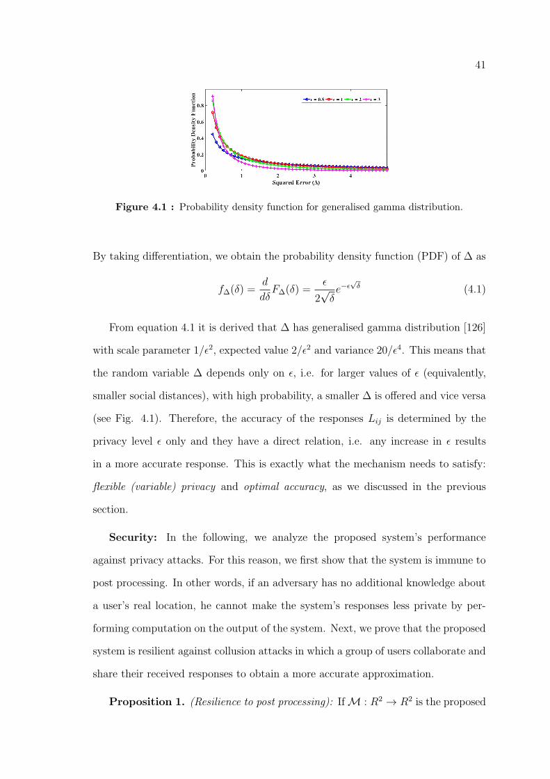
41
Figure 4.1 : Probability density function for generalised gamma distribution.
By taking differentiation, we obtain the probability density function (PDF) of ∆ as
f∆(δ) =d
dδF∆(δ) =
ε
2√δe−ε√δ (4.1)
From equation 4.1 it is derived that ∆ has generalised gamma distribution [126]
with scale parameter 1/ε2, expected value 2/ε2 and variance 20/ε4. This means that
the random variable ∆ depends only on ε, i.e. for larger values of ε (equivalently,
smaller social distances), with high probability, a smaller ∆ is offered and vice versa
(see Fig. 4.1). Therefore, the accuracy of the responses Lij is determined by the
privacy level ε only and they have a direct relation, i.e. any increase in ε results
in a more accurate response. This is exactly what the mechanism needs to satisfy:
flexible (variable) privacy and optimal accuracy, as we discussed in the previous
section.
Security: In the following, we analyze the proposed system’s performance
against privacy attacks. For this reason, we first show that the system is immune to
post processing. In other words, if an adversary has no additional knowledge about
a user’s real location, he cannot make the system’s responses less private by per-
forming computation on the output of the system. Next, we prove that the proposed
system is resilient against collusion attacks in which a group of users collaborate and
share their received responses to obtain a more accurate approximation.
Proposition 1. (Resilience to post processing): IfM : R2 → R2 is the proposed
42
mechanism which preserves ε–differential privacy, then for any function f : R2 → R2,
the composition f ◦M : R2 → R2 also preserves ε− differential privacy.
Proof: Assume location L′ is adjacent to L, i.e. ||L′ −L|| ≤ D (see definition 1)
and S ′ ⊂ R2. By defining S = {l ∈ R2 : f(l) ∈ S ′} and becauseM is a ε−differential
private mechanism we have
Pr[f(M(L)) ∈ S ′] = Pr[M(L) ∈ S] ≤ eεPr[(L′) ∈ S ′]
Therefore, according to the definition of S we obtain
Pr[f(M(L)) ∈ S ′] ≤ eεPr[f(M(L′)) ∈ S ′]
which means f ◦M is also ε−differential private.
Resilience to post processing is a common advantage of mechanisms that adopt
the differential privacy framework [9], [127]. It guarantees that after the system
publishes an ε−differential private response, an adversary without any additional
knowledge on the private data cannot increase privacy loss and make it less private
[128].
Therefore, the proposed mechanism is resilient to post processing. This makes it
immune to privacy attacks that rely solely on post processing. Moreover, we proof
that the proposed mechanism is also resilient to collusion attacks in which a group of
users combine their responses to make a more accurate approximation. In practice,
an adversary can create multiple fake accounts in the social network and establish
such a colluding group.
Theorem 1. (Resilience to collusions): Consider a group of K users C ⊆ V
who collaborate and share their response M(li, ε(dij)) = lij(j = 1, 2, . . . , K), (i ∈
V ) to obtain l(i)c . If lij be an ε(dij)−differentially private response, then l
(i)c is
(maxj∈Cε(dij)−differentially private.
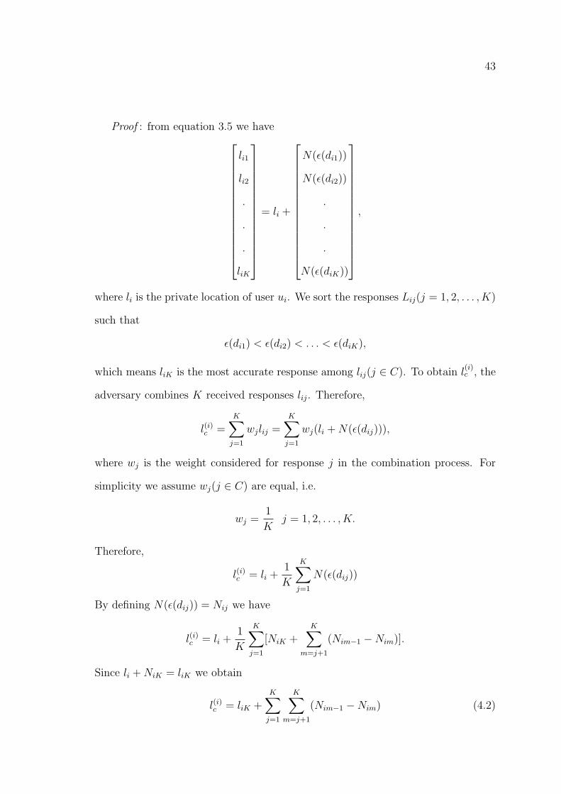
43
Proof : from equation 3.5 we have
li1
li2
.
.
.
liK
= li +
N(ε(di1))
N(ε(di2))
.
.
.
N(ε(diK))
,
where li is the private location of user ui. We sort the responses Lij(j = 1, 2, . . . , K)
such that
ε(di1) < ε(di2) < . . . < ε(diK),
which means liK is the most accurate response among lij(j ∈ C). To obtain l(i)c , the
adversary combines K received responses lij. Therefore,
l(i)c =K∑j=1
wjlij =K∑j=1
wj(li +N(ε(dij))),
where wj is the weight considered for response j in the combination process. For
simplicity we assume wj(j ∈ C) are equal, i.e.
wj =1
Kj = 1, 2, . . . , K.
Therefore,
l(i)c = li +1
K
K∑j=1
N(ε(dij))
By defining N(ε(dij)) = Nij we have
l(i)c = li +1
K
K∑j=1
[NiK +K∑
m=j+1
(Nim−1 −Nim)].
Since li +NiK = liK we obtain
l(i)c = liK +K∑j=1
K∑m=j+1
(Nim−1 −Nim) (4.2)
44
From equation 4.2 we can say that l(i)c consists of two parts. First, εiK−differential
private liK which is the most accurate response in C since εiK = maxj∈C εij and
second, a noise section. Since Nim−1 and Nim are independent Laplace– distributed
random variables, (Nim−1 − Nim) has also Laplace distribution. Therefore, we can
consider φ =∑K
j=1
∑Km=j+1(Nim−1−Nim) as Laplace-distributed noise added to liK .
In conclusion, we can say that l(i)c is the εiK−differential private response liK which
has been post processed by function g(x) = x = φ, i.e.
l(i)c = g(liK) = g(M(li)) = liK + φ.
According to proposition 1, mechanismM is immune to post processing, hence,
l(i)c is also εiK−differential private. Therefore, the result of any collusion attack is
equivalent to a (maxj∈C ε(dij))–differential private response which means no more
accuracy is obtained. Consequently, there is no need for additional privacy preserv-
ing noise when multiple users ask for a user’s private location.
4.3 Performance Evaluation
In this section, we evaluate the performance of our proposed DBLP2 system.
Firstly, we evaluate the proposed system’s performance regarding the four types
of users discussed in the previous section. Finally, we assess the immunity of the
proposed system against collusion attacks.
Variable Privacy: To evaluate the system performance in terms of variable
privacy, a single user scenario is considered in which the user’s location privacy is
protected against a variety of users. For this reason, we assess the magnitude of the
injected noise for a spectrum of users (i.e. from family members and close friends to
casual friends and strangers). To model this scenario, we increase the social distance
d from 0 to ∞ and obtain the related privacy level ε using the function introduced
in equation 3.4. Then, for each value of the obtained privacy level ε, the magnitude
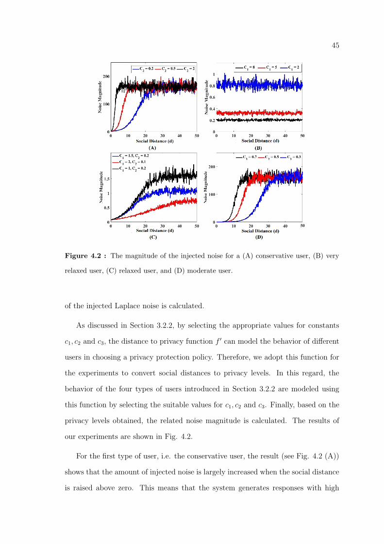
45
Figure 4.2 : The magnitude of the injected noise for a (A) conservative user, (B) very
relaxed user, (C) relaxed user, and (D) moderate user.
of the injected Laplace noise is calculated.
As discussed in Section 3.2.2, by selecting the appropriate values for constants
c1, c2 and c3, the distance to privacy function f ′ can model the behavior of different
users in choosing a privacy protection policy. Therefore, we adopt this function for
the experiments to convert social distances to privacy levels. In this regard, the
behavior of the four types of users introduced in Section 3.2.2 are modeled using
this function by selecting the suitable values for c1, c2 and c3. Finally, based on the
privacy levels obtained, the related noise magnitude is calculated. The results of
our experiments are shown in Fig. 4.2.
For the first type of user, i.e. the conservative user, the result (see Fig. 4.2 (A))
shows that the amount of injected noise is largely increased when the social distance
is raised above zero. This means that the system generates responses with high
46
accuracy for the user’s family members and close friends (who have small social
distance) while other users receive a totally inaccurate response. We performed
the experiments for three different values of constant c2 to see the effect of this
parameter. As you see, c2 determines the threshold social distance at which a tight
privacy protection (required by the user) starts. In other words, c2 represents how
a user is conservative. We have also selected c1 = 0 and c3 = 0.1 in this case (c1
must be zero for this type of user).
Fig. 4.2 (B) shows the result for a very relaxed user (c2 = c3 = 0). In this case,
c1 determines a high privacy level (relaxed privacy) which the user selects against all
the other users. As you see, the system always generates a very small noise regardless
of the social distance (a relatively accurate response for all the other users). The
level of this noise is determined by c1. In other words, for larger c1 (higher privacy
level) a more accurate response is generated. You can realise the difference between
the system responses generated for the first and second type of users (Fig. 4.2 (A)
and (B), respectively), if you compare the amount of the noise generated for each
category. Moreover, the amplitude of the changes in the amount of generated noise
is higher for a smaller c1. The reason is that the variance of the generated Laplace
noise is 2/ε2. Thus, the variance is increased as c1 is decreased.
The noise magnitude for the third type of user, i.e. the relaxed user, is shown
in Fig. 4.2 (C) for different values of c1 and c2 (c3 = 3 is selected in this case). The
noise magnitude for this type of user is almost the same as what we have in Fig. 4.2
(B) (notice the amount of noise magnitude in Fig. 4.2 (B) and Fig. 4.2 (C)). The
only difference is that in this case, the user requires less privacy protection for small
social distances while in the second type, there is no difference between different
social distances in terms of privacy protection.
Finally, for the last type of users, i.e. the moderate user, which we propose her
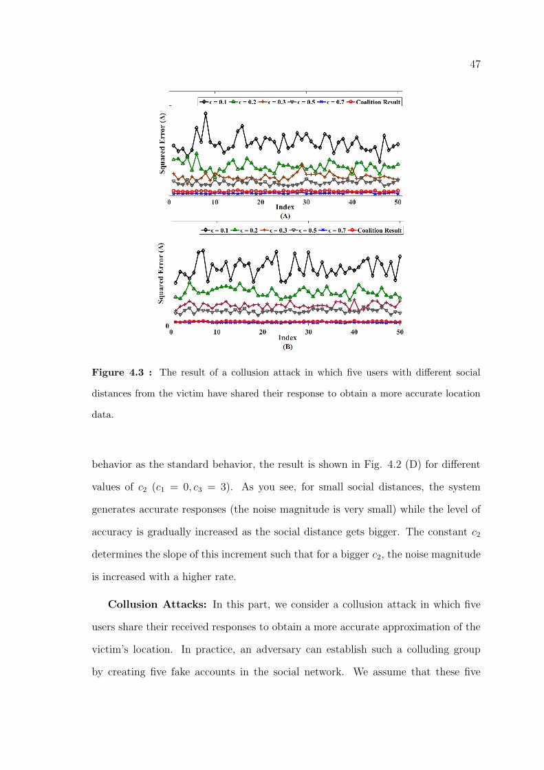
47
Figure 4.3 : The result of a collusion attack in which five users with different social
distances from the victim have shared their response to obtain a more accurate location
data.
behavior as the standard behavior, the result is shown in Fig. 4.2 (D) for different
values of c2 (c1 = 0, c3 = 3). As you see, for small social distances, the system
generates accurate responses (the noise magnitude is very small) while the level of
accuracy is gradually increased as the social distance gets bigger. The constant c2
determines the slope of this increment such that for a bigger c2, the noise magnitude
is increased with a higher rate.
Collusion Attacks: In this part, we consider a collusion attack in which five
users share their received responses to obtain a more accurate approximation of the
victim’s location. In practice, an adversary can establish such a colluding group
by creating five fake accounts in the social network. We assume that these five
48
users have different social distances from the victim. In other words, the victim
has different privacy levels ε1, ε2, . . . , ε5 against these five users. Hence, they receive
responses with different accuracy as well, i.e. the user with the largest ε (smallest
social distance) receives the most accurate response and vice versa. We compare
the accuracies of these responses and the collusion outcome to see if there exists any
motivation for an adversary to perform a collusion attack or not. In order to have
a better picture of the system performance, we have performed the experiments 50
times for each user and obtained the squared error ∆ of the five responses and the
outcome of the collusion in each iteration. You can see the result in Fig. 4.3.
As will be discussed in section 5.1, the resultant squared error is a random
variable with the generalised gamma distribution. Therefore, as Fig. 4.3 shows, a
different error has been obtained for a specific user for separate experiments. In
addition, the amplitude of these changes is higher in a response with a lower ε. The
reason is that the variance of the squared error ∆, i.e. 20/ε4, is larger for a lower ε.
Moreover, as we expect, the accuracy of each response only depends on the privacy
level ε(d). Consequently, in each iteration, the user with the lowest ε has received
the response with the largest error and vice versa.
You see in Fig. 4.3 that the outcome of the collusion attack is almost the same
as the most accurate response and has never been more accurate than it. This
confirms the results of our analysis in the previous subsection which states that the
result of any collusion attack is equivalent to a (maxj∈C ε(dij))–differential private
response. Consequently, there is no logical motivation for an adversary to conduct
such a collusion attack since no additional benefit can be gained.
Moreover, regarding the combination process of the responses, Fig. 4.3 (A)
shows the result of the experiments when the same weights have been considered for
the responses, i.e. the responses have equal share in creating the collusion result.
49
However, the results shown in Fig. 4.3 (B) is for a case in which the responses
have been combined with different weights. As you see, the same result has been
obtained in both cases which confirms that the combination process does not affect
the immunity of the system against collusion attacks.
4.4 Conclusion
In this chapter, we presented the results of our analysis and performance eval-
uation of the proposed DBLP2 mechanism. The proposed mechanism returns a
customised response through the differential privacy mechanism whenever a user
requests to access another user’s location information. Moreover, DBLP2 improves
data utility by generating responses with optimal accuracy and providing privacy–aware
access rights for different users. Our extensive analysis shows that it offers the op-
timum data utility regarding the trade–off between privacy protection and data
utility. In addition, our experimental results indicate that DBLP2 is capable of
offering variable location privacy protection and resilience to post processing.
In the next part of the thesis, we explore the crytography–based approach for
privacy preserving in social networks. In this regard, three diffrent cryptography–
based solutions are introduced and their performance is analysed and evaluated.

50
Part II
Cryptography–Based Approach
51
Chapter 5
Literature Review and Preliminaries
5.1 Introduction
In recent years, advancements in smartphone technology and positioning systems
have resulted in the emergence of location–based applications and services such
as activity–tracking applications, location–based services (LBS), database–driven
cognitive radio networks (CRNs), and location–based access control systems. In
these services, mobile users’ real–time location data is utilised by a location–based
service provider (LBSP) to provide users with requested information or access to a
resource or service. These applications are fast growing and very popular due to the
range of useful services they offer [14], [17–19].
However, it is possible for dishonest users to submit fake check–ins by changing
their GPS data. To clarify and highlight the fake location submission issue consider
LBSPs like Yelp and Foursquare that may offer some rewards (such as gift vouchers)
to users who frequently check in at specific locations. This creates an incentive for
dishonest users to submit fake check–ins by manipulating their GPS data. For ex-
ample, in a research study, Zhang et al. [26] found that 75% of Foursquare check–ins
are false and submitted by dishonest users to obtain more rewards. Furthermore, in
database–driven CRNs, malicious users can submit fake locations to the database
to access channels which are not available in their location [23, 25, 32].
In this chapter, we highlight and review the existing location verification schemes.
These schemes are also called location proof (LP) schemes in the literature. More-
over, we present some preliminaries as the foundation for the next three chapters.
52
5.2 Literature Review
In this section, we review the literature on location proof (LP) schemes. They
are generally categorised into two groups depending on the system architecture:
centralized and distributed. In the centralized schemes, a trusted fixed wireless
infrastructure, usually a WiFi access point, is employed to check the proximity of
mobile users and generate LPs for them. On the other hand, in the decentralized
schemes, this task is done by ordinary mobile users who act as witnesses and issue
LPs for each other. This makes their implementation easier and cheaper than the
centralized mechanisms. In this section, we review the related literature on each
category separately.
5.2.1 Centralized Schemes
In this approach, a central trusted node such as a wireless access point is utilised
to generate LPs for users in a specific site. The idea of employing wireless access
points as location proof generators was introduced by Waters et al. [83] for the
first time. They measure the round–trip signal propagation latency to decide on the
proximity of a user to a trusted access point referred to as the location manager.
However, the proposed scheme is vulnerable against relay attacks and specifically
against Terrorist Frauds. In other words, their algorithm lacks a mechanism by
which the location manager ensures that the received ID is really for the user who
has submitted the LP request.
To address this issue, Saroiu et al. [84] proposed a technique in which the access
point broadcasts beacon frames consisted of a sequence number. To obtain an LP,
users must sign the last transmitted sequence number with their private key and send
it back to the access point along with their public key (the access point broadcasts
beacons every 100 milliseconds). This makes the system resistant against Terrorist
Frauds since the malicious prover does not have enough time to receive the sequence
53
number from the adversary, sign and send it back to the adversary. However, the
proposed algorithm has privacy issues because users must reveal their identity pub-
licly. Javali et al. [85] have used the same idea to make their algorithm resistant
against relay attacks. They also utilise the unique wireless channel characteristics,
i.e., channel state information (CSI) to decide on users’ proximity. The proposed
scheme consists of three entities, i.e., Access Point, Verifier and Server which makes
the system expensive. In addition, the user’s identity is revealed publicly which
might cause privacy issues. Table 5.1 presents a comparison of these LP schemes.
5.2.2 Distributed Schemes
In the distributed scenarios, users collaborate with the system to generate LPs.
In other words, users act as witnesses for each other. The main advantage of this
approach is that there is no need for a trusted access point to issue LPs. Therefore,
this type of systems can be used in locations where users are far from a trusted entity.
APPLAUS introduced by Zhu et al. [86] is one of the pioneer research works on dis-
tributed location proof systems. In APPLAUS, mobile devices use their short–range
Bluetooth interface to communicate with their nearby devices who request an LP.
To preserve users’ location privacy, they need to select a set of M pseudonyms and
change them periodically. These pseudonyms are considered as users’ public keys
which are required to be registered with a trusted Certificate Authority (CA) along
with the associated private keys. However, changing pseudonyms regularly creates
a high level of computation and communication overhead. In addition, the users are
required to generate dummy LPs as well.
Davis et al. proposed a privacy–preserving alibi (location proof) scheme in [87]
which has a distributed architecture. To preserve users’ location privacy, in the
introduced scheme, their identity is not revealed while an alibi is being created.
Thus, only a judge with whom a user submits his/her alibi can see the user’s identity.
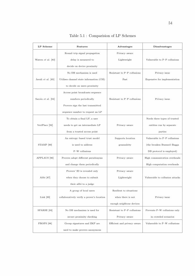
54
Table 5.1 : Comparision of LP Schemes
LP Scheme Features Advantages Disadvantages
Round–trip signal propagation Privacy–aware
Waters et al. [83] delay is measured to Lightweight Vulnerable to P–P collusions
decide on device proximity
No DB mechanism is used Resistant to P–P collusions Privacy issue
Javali et al. [85] Utilises channel state information (CSI) Fast Expensive for implementation
to decide on users proximity
Access point broadcasts sequence
Saroiu et al. [84] numbers periodically Resistant to P–P collusions Privacy issue
Provers sign the last transmitted
sequence number to request an LP
To obtain a final LP, a user Needs three types of trusted
VeriPlace [92] needs to get an intermediate LP Privacy–aware entities run by separate
from a trusted access point parties
An entropy–based trust model Supports location Vulnerable to P–P collusions
STAMP [90] is used to address granualrity (the broaken Bussard–Bagga
P–W collusions DB protocol is employed)
APPLAUS [86] Provers adopt different pseudonyms Privacy–aware High communication overheads
and change them periodically High computation overheads
Provers’ ID is revealed only Privacy–aware
Alibi [87] when they choose to submit Lightweight Vulnerable to collusion attacks
their alibi to a judge
A group of local users Resilient to situations
Link [89] collaboratively verify a prover’s location when there is not Privacy issue
enough neighbour devices
SPARSE [93] No DB mechanism is used for Resistant to P–P collusions Prevents P–W collusions only
secure proximity checking Privacy–aware in crowded scenarios
PROPS [88] Group signatures and ZKP are Efficient and privacy–aware Vulnerable to P–W collusions
used to make provers anonymous
55
However, collusions and other security threats have not been considered in the paper.
In the distributed solutions, Prover–Witness collusions are possible because wit-
ness devices are not always trusted. A witness device can issue an LP for a dishonest
user while one of them (or both) is not located at the claimed location. This is one
of the major challenges of these schemes. For example, in PROPS which has been
proposed by Gambs et al. [88], Prover–Witness collusions have not been discussed
although it provides an efficient and privacy–aware platform for users to create LPs
for other users.
To the best of our knowledge, there is no efficient and reliable solution proposed
in the literature to resolve the Prover–Witness collusions issue with a high level
of reliability even though some significant efforts have been made so far. For ex-
ample, in LINK introduced by Talasila et al. [89] a group of users collaboratively
verify a user’s location upon his/her request sent through a short–range Bluetooth
interface. It is assumed that there is a trusted Location Certification Authority
(LCA) to which the verifying users (located in the vicinity of the requesting user)
send their verification messages. Then, the LCA checks validity of the claim in
case of a Prover–Witness collusion. This is done by checking three parameters: the
spatiotemporal correlation between the prover and verifiers, the trust scores of the
users, and the history of the trust scores. However, it does not detect and prevent
Prover–Witness collusions with a high level of reliability. Moreover, in the LINK
scheme, users’ location privacy has not been considered in the scheme design since
a user needs to broadcast his/her ID to the neighbour verifiers.
STAMP introduced by Wang et al. [90] is another example in which an en-
tropy–based trust model is proposed to address the Prover–Witness collusions is-
sue. This method is also unable to provide the necessary reliability to detect
Prover–Witness collusions. In addition, to address Terrorist Frauds, STAMP em-
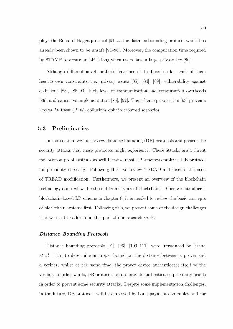
56
ploys the Bussard–Bagga protocol [91] as the distance bounding protocol which has
already been shown to be unsafe [94–96]. Moreover, the computation time required
by STAMP to create an LP is long when users have a large private key [90].
Although different novel methods have been introduced so far, each of them
has its own constraints, i.e., privacy issues [85], [84], [89], vulnerability against
collusions [83], [86–90], high level of communication and computation overheads
[86], and expensive implementation [85], [92]. The scheme proposed in [93] prevents
Prover–Witness (P–W) collusions only in crowded scenarios.
5.3 Preliminaries
In this section, we first review distance bounding (DB) protocols and present the
security attacks that these protocols might experience. These attacks are a threat
for location proof systems as well because most LP schemes employ a DB protocol
for proximity checking. Following this, we review TREAD and discuss the need
of TREAD modification. Furthermore, we present an overview of the blockchain
technology and review the three diferent types of blockchains. Since we introduce a
blockchain–based LP scheme in chapter 8, it is needed to review the basic concepts
of blockchain systems first. Following this, we present some of the design challenges
that we need to address in this part of our research work.
Distance–Bounding Protocols
Distance–bounding protocols [91], [96], [109–111], were introduced by Brand
et al. [112] to determine an upper bound on the distance between a prover and
a verifier, whilst at the same time, the prover device authenticates itself to the
verifier. In other words, DB protocols aim to provide authenticated proximity proofs
in order to prevent some security attacks. Despite some implementation challenges,
in the future, DB protocols will be employed by bank payment companies and car
57
manufacturers due to recent advances [96].
All DB protocols work based on the fact that RF signals do not travel faster
than light. First, the verifier sends a challenge bit and the prover replies promptly
by sending the corresponding response regarding the received challenge bit. This
procedure is called fast bit exchange in the literature. Then, the verifier measures
the related round–trip time (RTT ) which must be less than a specified threshold.
This threshold is obtained by computing RTTmax that is related to the maximum
allowed distance to the prover and is obtained through the following equation:
RTTmax =2dmaxC
+ to ,
where dmax is the maximum allowed distance, C is the speed of light, and to is an
overhead time that is added to cover the computation time [95]. This process is
repeated n rounds with n different challenge bits (where n is the length of prover’s
private key). Finally, the verifier either accepts or rejects the prover’s claim.
In addition to the proximity checking, the verifier must authenticate the neigh-
bor prover at the same time. Otherwise, an adversary can collude with a remote
malicious prover and perform the fast bit exchange mechanism on behalf of the re-
mote prover. In this regard, there are some security attacks that a well–designed DB
protocol must be resistant against. In the literature, the following security threats
have been identified so far [96]. These attacks threat an LP scheme as well since
most of the LP schemes employ a DB protocol as their core function.
Distance Frauds: In a distance fraud, a malicious prover tries to convince an
honest verifier that his physical distance to the verifier is less than what it really
is (see Fig. 5.1 (a)). This attack can occur if there is no relationship between
challenge bits and response bits and the malicious prover knows the time at which
the challenge bits are sent. In this case, the malicious prover can send each response
bit before its challenge bit is received.
58
Figure 5.1 : Distance–bounding protocols are generally exposed to three types of security
attacks: (a) Distance Fraud, (b) Mafia Fraud, and (c) Terrorist Fraud.
Mafia Frauds: In this attack, an adversary tries to convince an honest verifier
that a remote honest prover is in the vicinity of the verifier. The adversary in this
attack can be modeled by a malicious prover that communicates with the honest
verifier and a malicious verifier who interacts with the honest prover (Fig. 5.1 (b)).
The car locking system is a good example to understand this type of attacks where
an adversary tries to open a car’s door by convincing the reader unit that the key
is close to the car.
Terrorist Frauds: In this attack, a remote malicious prover colludes with an
adversary who is close to an honest verifier to convince the verifier that he/she is
in the vicinity of the verifier (see Fig. 5.1 (c)). Although in their collusion, they
never share private information (e.g., private key) with each other, it is still possible
that they establish a very fast communication tunnel between themselves and the
adversary relays the verifier’s message to the malicious prover who can sign and send
it back to the adversary for submission. Therefore, just a simple assumption that
users never share their private key can not protect the system against this type of
attacks.
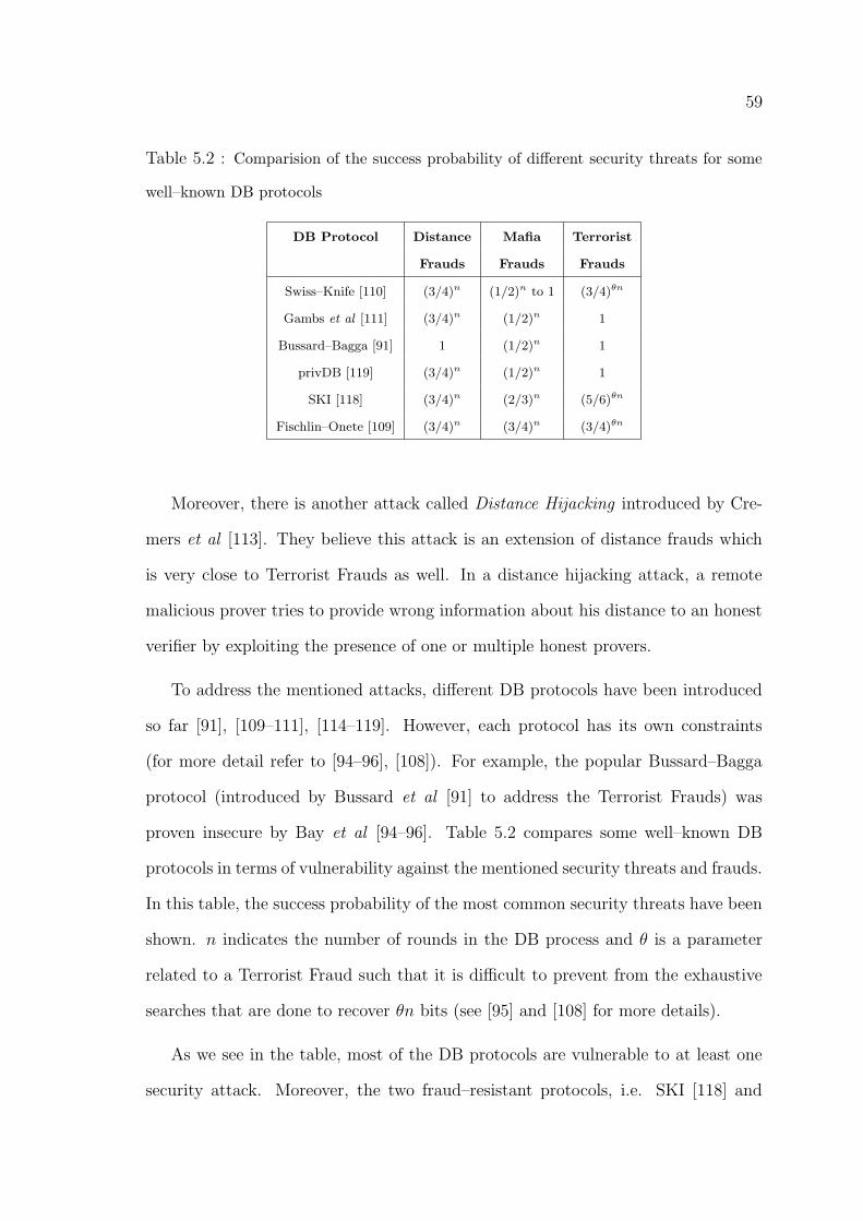
59
Table 5.2 : Comparision of the success probability of different security threats for some
well–known DB protocols
DB Protocol Distance Mafia Terrorist
Frauds Frauds Frauds
Swiss–Knife [110] (3/4)n (1/2)n to 1 (3/4)θn
Gambs et al [111] (3/4)n (1/2)n 1
Bussard–Bagga [91] 1 (1/2)n 1
privDB [119] (3/4)n (1/2)n 1
SKI [118] (3/4)n (2/3)n (5/6)θn
Fischlin–Onete [109] (3/4)n (3/4)n (3/4)θn
Moreover, there is another attack called Distance Hijacking introduced by Cre-
mers et al [113]. They believe this attack is an extension of distance frauds which
is very close to Terrorist Frauds as well. In a distance hijacking attack, a remote
malicious prover tries to provide wrong information about his distance to an honest
verifier by exploiting the presence of one or multiple honest provers.
To address the mentioned attacks, different DB protocols have been introduced
so far [91], [109–111], [114–119]. However, each protocol has its own constraints
(for more detail refer to [94–96], [108]). For example, the popular Bussard–Bagga
protocol (introduced by Bussard et al [91] to address the Terrorist Frauds) was
proven insecure by Bay et al [94–96]. Table 5.2 compares some well–known DB
protocols in terms of vulnerability against the mentioned security threats and frauds.
In this table, the success probability of the most common security threats have been
shown. n indicates the number of rounds in the DB process and θ is a parameter
related to a Terrorist Fraud such that it is difficult to prevent from the exhaustive
searches that are done to recover θn bits (see [95] and [108] for more details).
As we see in the table, most of the DB protocols are vulnerable to at least one
security attack. Moreover, the two fraud–resistant protocols, i.e. SKI [118] and
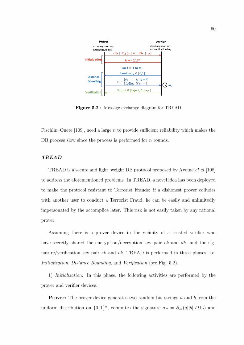
60
Figure 5.2 : Message exchange diagram for TREAD
Fischlin–Onete [109], need a large n to provide sufficient reliability which makes the
DB process slow since the process is performed for n rounds.
TREAD
TREAD is a secure and light–weight DB protocol proposed by Avoine et al [108]
to address the aforementioned problems. In TREAD, a novel idea has been deployed
to make the protocol resistant to Terrorist Frauds: if a dishonest prover colludes
with another user to conduct a Terrorist Fraud, he can be easily and unlimitedly
impersonated by the accomplice later. This risk is not easily taken by any rational
prover.
Assuming there is a prover device in the vicinity of a trusted verifier who
have secretly shared the encryption/decryption key pair ek and dk, and the sig-
nature/verification key pair sk and vk, TREAD is performed in three phases, i.e.
Initialization, Distance Bounding, and Verification (see Fig. 5.2).
1) Initialization: In this phase, the following activities are performed by the
prover and verifier devices:
Prover: The prover device generates two random bit–strings a and b from the
uniform distribution on {0, 1}n, computes the signature σP = Ssk(a||b||IDP ) and
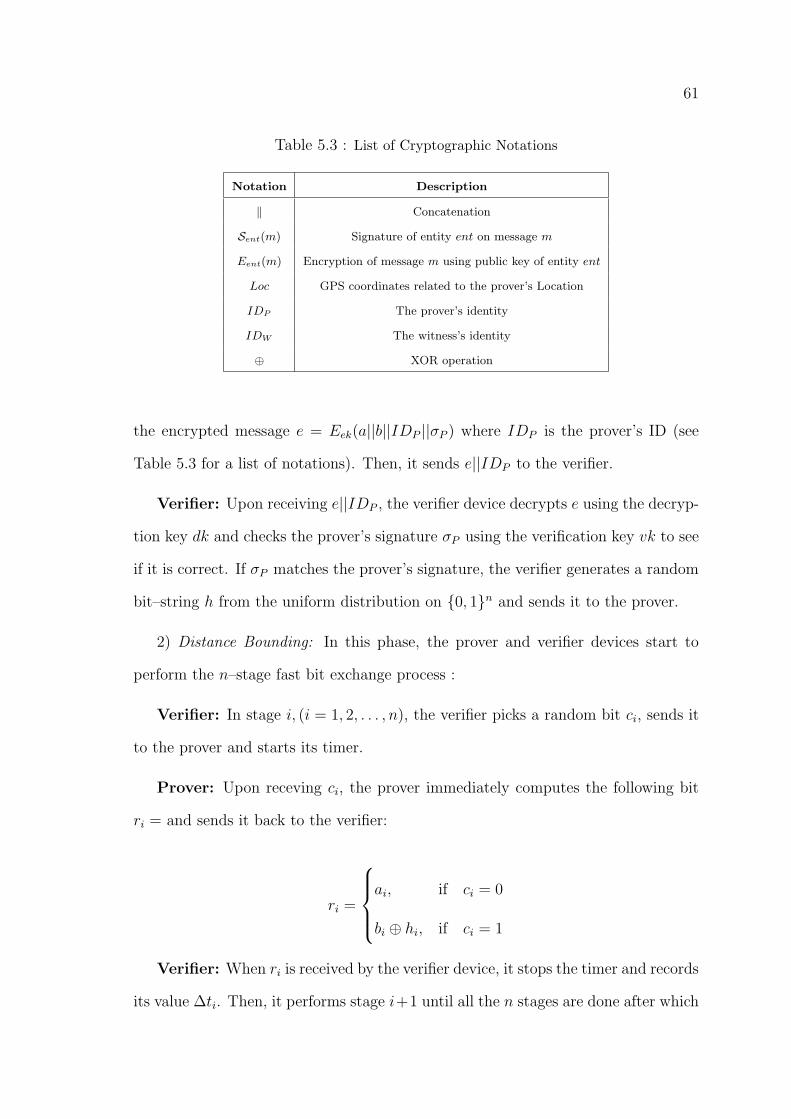
61
Table 5.3 : List of Cryptographic Notations
Notation Description
‖ Concatenation
Sent(m) Signature of entity ent on message m
Eent(m) Encryption of message m using public key of entity ent
Loc GPS coordinates related to the prover’s Location
IDP The prover’s identity
IDW The witness’s identity
⊕ XOR operation
the encrypted message e = Eek(a||b||IDP ||σP ) where IDP is the prover’s ID (see
Table 5.3 for a list of notations). Then, it sends e||IDP to the verifier.
Verifier: Upon receiving e||IDP , the verifier device decrypts e using the decryp-
tion key dk and checks the prover’s signature σP using the verification key vk to see
if it is correct. If σP matches the prover’s signature, the verifier generates a random
bit–string h from the uniform distribution on {0, 1}n and sends it to the prover.
2) Distance Bounding: In this phase, the prover and verifier devices start to
perform the n–stage fast bit exchange process :
Verifier: In stage i, (i = 1, 2, . . . , n), the verifier picks a random bit ci, sends it
to the prover and starts its timer.
Prover: Upon receving ci, the prover immediately computes the following bit
ri = and sends it back to the verifier:
ri =
ai, if ci = 0
bi ⊕ hi, if ci = 1
Verifier: When ri is received by the verifier device, it stops the timer and records
its value ∆ti. Then, it performs stage i+1 until all the n stages are done after which
62
it goes to the verification phase.
3) Verification: In this phase, the verifier device checks all the received ri for
i = 1, 2, . . . , n to see if they have been correctly computed based on hi, ci, ai and bi
(the last two bits received in the initialization phase). Then ∆ti must be less than
the predefined threshold RTTmax for i = 1, 2, . . . , n.
Finally, the prover’s request is accepted if the above checkings are successfully
passed for all n stages.
As we see, in case of a Terrorist Fraud, a dishonest prover (located far from
the verifier) not only has to provide the accomplice with his σP and e, but also
his random bit–strings a and b. Otherwise, the accomplice is unable to correctly
respond to the challenge bits ci in the DB phase. This enables the accomplice to
easily impersonate him later using a, b, σP , and e. See [108] for a comprehensive
security analysis on TREAD.
TREAD Modification
In spite of the security guarantees that TREAD offers, it needs some amendment
before we make use of it in our proposed architecture. In the following, we show
how the prover’s location privacy is negatively affected, if TREAD is integrated into
PASPORT without any customization.
In TREAD, the prover’s ID is sent to a neighbor verifier (which is assumed to
be trusted) through a short–range communication interface. Due to PASPORT’s
decentralized architecture, the trusted verifier is located far away from the prover.
Instead, a witness device (which is untrusted from a privacy point of view) collects
the prover’s data and performs the DB procedure. Thus, the prover’s ID is sent to
the witness devices in the form of a plain text message if we integrate TREAD into
PASPORT without any modification. This breaches the prover’s location privacy.
63
Hence, it is necessary to modify TREAD and make it a privacy–aware DB protocol.
Note that prover anonymity can be offered by TREAD if group signatures are
used [108]. However, they guarantee provers’ anonymity up to group level only.
Since we do not want to use group signatures in the PASPORT’s architecture, in
the next section, we propose a private version of TREAD, i.e. P–TREAD, by which
a prover device can anonymously broadcast its LP request for neighbor witnesses
while he/she benefits from the TREAD security guarantees.
5.3.1 Blockchain Overview
A blockchain system is a tamper–proof and tamper–apparent ledger that is dig-
itally implemented using a distributed approach without requiring a central storage
system. It can also be implemented in such a way that no central authority is re-
quired to operate and maintain the whole system. The distributed ledger consists of
users transactions that are cryptographically signed by them. A group of transac-
tions create a block. Thus, the distributed ledger is made of blocks of transactions.
Users generate their transactions and broadcast them in the network where they
can be read by verifiers for verification. A verifier can be either an ordinary user
(in public blockchains) or an authorized user or entity (in private and consortium
blockchains). Once a transaction is verified, it is added to a new block. After a
new block is issued (added to the ledger), it is computationally infeasible to tamper
its transactions [121], [122]. The reason is that each block contains the hash of its
previous block. This links every block to its previous block which results in having
a chain of blocks.
Generally, blockchains can be divided into the following three categories based
on their permission model, which determines who can operate and maintain the
system (e.g., generate a new block).

64
• Public blockchains: In a public blockchain system, any user can verify trans-
actions and generate a new block. This type of blockchain systems is also
called permissionless blockchain in which the system allows anyone to join the
network with both read and write permissions. Bitcoin is an example of a
public blockchain.
• Private blockchains: In private blockchains, only specific users or entities can
verify transactions and generate a new block. In other words, the system is
controlled by an organization that manages access permissions. Thus, not all
the users have access to the detail of the transactions stored in the ledger.
• Consortium blockchains: These systems are actually private blockchains that
are employed by a group of organizations. A consortium blockchain is con-
sidered as a semi-decentralized blockchain that usually adopts a hybrid access
method. Quorum and Corda are two examples of consortium blockchains.
It is proposed that the LP scheme proposed in this research work is implemented
as a public blockchain system. This has several advantages including complete
decentralization (independent of a trusted third party), full transparency of the
public ledger, more security (due to use of incentivized validation that results in more
miners contributing to validations), and self–sustainability. However, depending on
the application scenario, the proposed scheme can be implemented as a private or
consortium blockchain as well.
5.3.2 Design Challenges:
Blockchain technology has created a great opportunity to design decentralized
systems for different applications. However, some novel features of a blockchain–based
architecture introduce a number of design challenges for our work. For example,
recording users’ location data in a public ledger contradicts their location privacy.
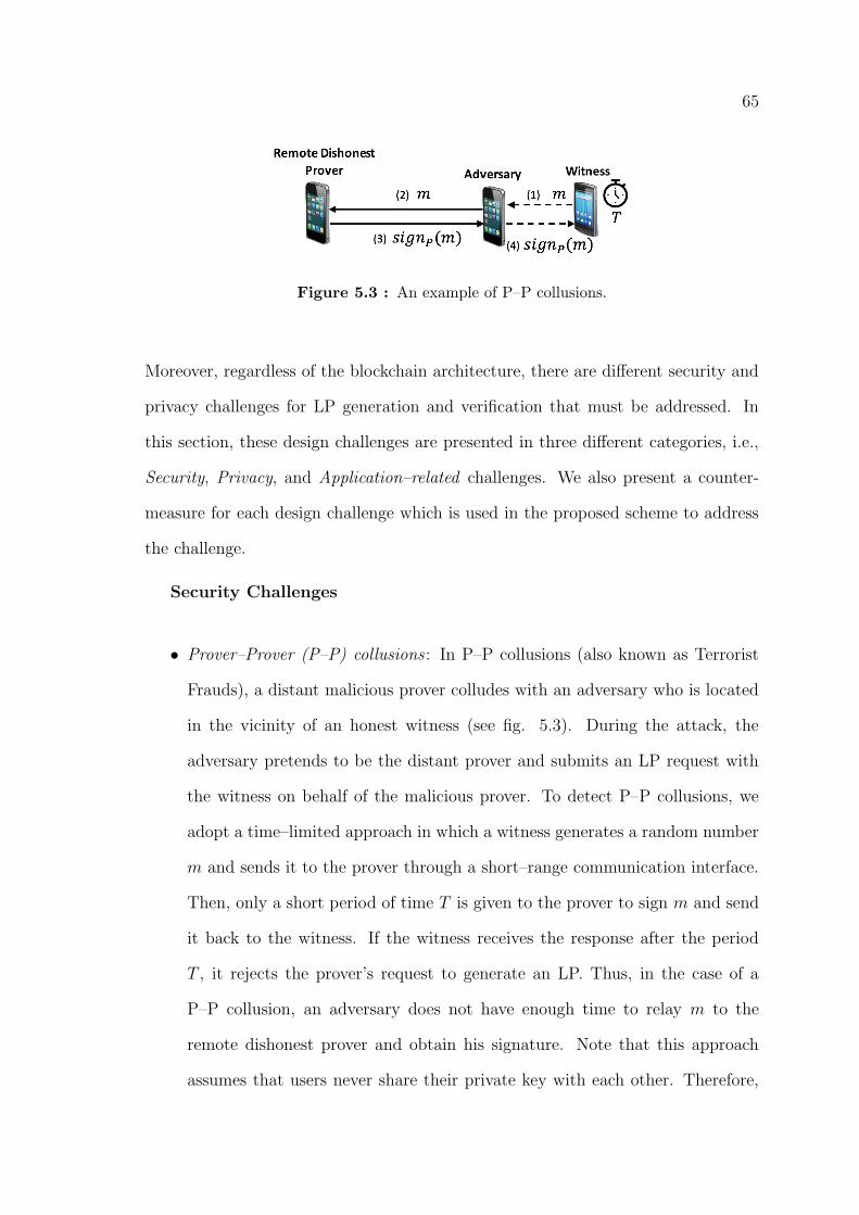
65
Figure 5.3 : An example of P–P collusions.
Moreover, regardless of the blockchain architecture, there are different security and
privacy challenges for LP generation and verification that must be addressed. In
this section, these design challenges are presented in three different categories, i.e.,
Security, Privacy, and Application–related challenges. We also present a counter-
measure for each design challenge which is used in the proposed scheme to address
the challenge.
Security Challenges
• Prover–Prover (P–P) collusions : In P–P collusions (also known as Terrorist
Frauds), a distant malicious prover colludes with an adversary who is located
in the vicinity of an honest witness (see fig. 5.3). During the attack, the
adversary pretends to be the distant prover and submits an LP request with
the witness on behalf of the malicious prover. To detect P–P collusions, we
adopt a time–limited approach in which a witness generates a random number
m and sends it to the prover through a short–range communication interface.
Then, only a short period of time T is given to the prover to sign m and send
it back to the witness. If the witness receives the response after the period
T , it rejects the prover’s request to generate an LP. Thus, in the case of a
P–P collusion, an adversary does not have enough time to relay m to the
remote dishonest prover and obtain his signature. Note that this approach
assumes that users never share their private key with each other. Therefore,
66
the adversary cannot sign m on behalf of the remote prover.
• Prover–Witness (P–W) collusions : In this collusion scenario, a dishonest wit-
ness colludes with a distant malicious prover and issues a fake LP for him.
P–W collusions are the most difficult challenges to address in this area of re-
search. To the best of our knowledge, no reliable and effective solution has
been offered in the literature so far to address these attacks. In this research
work, we adopt a novel mechanism to address P–W collusions in which an
attacker (a dishonest witness who wants to generate a fake LP for a remote
dishonest prover) is forced to change his attack to a P–P collusion attack.
Therefore, the P–W collusion is detected since the proposed scheme detects
P–P collusions through the presented time–limited approach.
Privacy Challenges
To design an LP system using the blockchain architecture, one possible approach
is that we record users’ plaintext spatiotemporal data in a public ledger. However,
this approach contradicts users’ location privacy because their spatiotemporal data
is shown publicly. In addition, it has been shown that even if users hide their real
identity (which is common in blockchain systems) it is still possible to identify a user
by analyzing the history of his/her spatiotemporal data [14], [106]. Thus, adopting
a pseudonym by users cannot guarantee their location privacy.
To address this challenge, we adopt a novel approach in which users commit
to their spatiotemporal data before they create a transaction. These commitments
are then added to the transaction and will be stored in the public ledger after
verification:
C(P,ST ) = Commit(ST, r), (5.1)
where ST = (Loc, T ime) is the spatiotemporal data of the user (prover) and r is a
random nonce generated by him/her for the commitment to ST .
67
When a user submits a location claim with a LBSP, he/she opens the commit-
ment by sending r to the LBSP. Therefore, if the user loses this r, his/her location
claim will not be confirmed by the LBSP. This is similar to a user wanting to spend
his/her Bitcoin money (in Bitcoin, users cannot spend the money in their wallet if
their private key is lost). Therefore, it is infeasible to obtain the history of a user’s
spatiotemporal data by analyzing his/her transactions stored in the public ledger.
Application–Related Challenges
In this subsection, we present two critical challenges that may result in negative
impacts on the performance of LP schemes if not addressed.
• Challenge 1 : A big challenge for our decentralized scheme lies in how we can
convince mobile users to act as a witness since they generally tend to reject
requests to generate LPs if there is not enough incentive for them (for example,
to save on battery consumption). To address this problem, we integrate an
incentive mechanism into our proposed LP scheme to reward users who collab-
orate with the system with a specific amount of cryptocurrency. The LBSPs
can make this currency valuable by exchanging them for rewards, badges and
benefits that they are currently providing to their users (see [26] and [84] for
more details and examples). Moreover, other businesses such as insurance
companies and government agencies that might utilize LPs of their customers
can contribute to make the currency more valuable. This creates the necessary
incentive for mobile users and verifiers to collaborate with the system.
• Challenge 2 : Speed is another challenge for an LP system that needs to be
addressed. As far as we know, the majority of the LP schemes which have been
proposed in literature so far utilize a DB protocol to check the proximity of a
prover to a witness. This not only requires some hardware changes on mobile
devices, but also makes the LP generation process slow when users adopt a long
68
private key [85] since a prover device must respond to m challenge messages
that a witness sends to it, where m is the size of the prover’s private key. This
process is called fast–bit–exchange in literature.
In the proposed system design, we do not adopt a DB protocol to check the
proximity of a prover to a witness. Instead, the time–limited mechanism (discussed
in the security challenges) enables the witness to check whether the prover is really
located in its vicinity or not. This makes the LP generation process much faster
than the current solutions.
5.4 Conclusion
In this chapter, we reviewed the existing literature on the current location verifi-
cation solutions in location–based social networks and reviewed the advantages and
disadvantages of each solution. It is concluded that although different LP schemes
have been introduced so far, they suffer from at least one of the following problems:
location privacy issue, vulnerability against collusions, high level of communication
and computation overheads, and expensive implementation.
Moreover, this chapter presented some preliminaries as the foundation for the
next chapter. In this regard, we reviewed distance bounding (DB) protocols and
presented the security attacks that these protocols might experience. Following
this, we reviewed TREAD as a promising distance bounding protocol and discuss
the need of TREAD modification. Furthermore, we presented an overview of the
blockchain technology and review the three diferent types of blockchains. Finally,
we presented some of the design challenges that we need to address in this part of
our research work.
In the next chapter, we introduce our first location proof scheme, i.e. Privacy-
Aware and Secure Proof Of pRoximiTy (PASPORT) scheme. which performs LP
69
generation and verification for mobile users in a secure and privacy–aware manner.
The proposed scheme provides the integrity and non–transferablity of generated
LPs.
70
Chapter 6
PASPORT: Secure and Private Location Proof
Generation and Verification
6.1 Introduction
Recently, there has been a rapid growth in location–based systems and applica-
tions in which users submit their location information to service providers in order
to gain access to a service, resource or reward. We have seen that in these applica-
tions, dishonest users have an incentive to cheat on their location. Now, we present
some examples to highlight relevant issues in these applications.
• A significant percentage of Foursquare check–ins are fake and created by dis-
honest users to obtain in–system rewards (such as gift vouchers) offered to
users who frequently check–in at specific locations [26]. LBSPs like Yelp and
Foursquare offer some rewards (such as gift vouchers) to their users who fre-
quently check–in at specific locations. This encourages dishonest users to
submit fake check–ins by manipulating their GPS data. In a research study,
Zhang et al [26] found that almost 75% of Foursquare check–ins are false and
submitted by dishonest users to obtain more rewards.
• In the current online rating and review applications, users’ real location is
not verified which enables them to submit fake positive or negative reviews
for their own business or their rivals, respectively [27–28]. Online ratings and
reviews have a significant impact on the revenue of businesses. Thus, dishonest
users have an incentive to create either fake positive or negative reviews for
their own business or their rivals, respectively [26]. Specifically, using the new
71
crowdsourcing platforms like Mechanical Turk [28], it is less challenging to
create a large number of fake reviews. Unfortunately, in the current online
rating and review platforms, users’ real location is not verified which enables
them to submit fake reviews.
• Activity–tracking applications such as RunKeeper and Endomondo enable
users to monitor their physical activities like running or cycling and share
their location–based activities with the service providers and other users in so-
cial networks [24]. Using these applications, users share their location–based
activities with the service providers and other users in social networks. To
encourage users, the service providers offer different incentives for them such
as vouchers, discounts, or awards [29–31].
• CRNs [23], [25], [32], as a typical LBS, are an efficient solution for the spectrum
management issue in large–scale IoT systems [23]. In this approach, to increase
spectrum utilisation, available frequency channels in a specific area are offered
to unlicensed radio users located at the region when the channels are not
occupied by licensed users. These networks are vulnerable to location spoofing
attacks since malicious users can submit fake locations to the database to
access channels which are not available in their location. This may cause
severe signal interference for the neighbour primary users [23], [33].
• In location–based access control applications [34–36], attackers can gain unau-
thorized access to a system or resource by submitting fake location claims.
• In activity–tracking applications, insurance companies may offer health insur-
ance plans in which customers are offered discounts if they have a minimum
level of physical activity [24], [29–31]. This creates an incentive for dishonest
users to cheat on their location data.
72
Unfortunately, no effective protection mechanism has been adopted by service providers
against these fake location submissions. This is a critical issue that causes severe
consequences for these applications. Motivated by this, we propose three location
verification schemes in this section to address the problem, i.e., (1) Privacy-Aware
and Secure Proof Of pRoximiTy (PASPORT), (2) Secure, Privacy–Aware and collu-
sion Resistant poSition vErification (SPARSE), and (3) a blockchain–based location
verification scheme. Using PASPORT, users submit a location proof (LP) to service
providers to prove that their submitted location is true. PASPORT has a decen-
tralized architecture designed for ad hoc scenarios in which mobile users can act as
witnesses and generate location proofs for each other. It provides user privacy pro-
tection as well as security properties, such as unforgeability and non–transferability
of location proofs. Furthermore, the PASPORT scheme is resilient to Prover–Prover
collusions and significantly reduces the success probability of Prover–Witness collu-
sion attacks. To further make the proximity checking process private, we propose
PTREAD, a privacy–aware distance bounding protocol and integrate it into PAS-
PORT. To validate our model, we implement a prototype of the proposed scheme
on the Android platform. Extensive experiments indicate that the proposed method
can efficiently protect location–based applications against fake submissions.
6.2 Background
The recent advances in the smartphone technology and positioning systems has
resulted in the emergence of a variety of location–based applications and services
[17–19] such as activity–tracking applications, location–based services, database–
driven cognitive radio networks (CRNs), and location–based access control systems.
In these applications, mobile users submit their position data to a location–based
service provider (LBSP) to gain access to a service, resource, or reward. These
applications are very popular due to the useful services they offer. According to
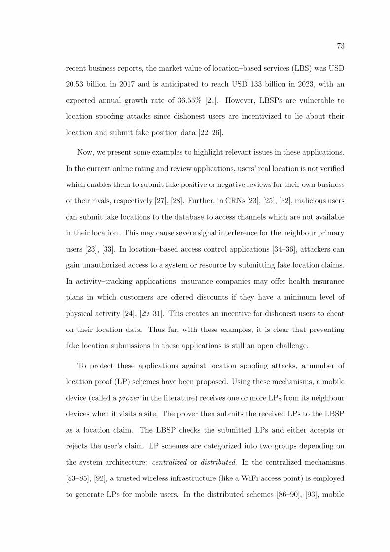
73
recent business reports, the market value of location–based services (LBS) was USD
20.53 billion in 2017 and is anticipated to reach USD 133 billion in 2023, with an
expected annual growth rate of 36.55% [21]. However, LBSPs are vulnerable to
location spoofing attacks since dishonest users are incentivized to lie about their
location and submit fake position data [22–26].
Now, we present some examples to highlight relevant issues in these applications.
In the current online rating and review applications, users’ real location is not verified
which enables them to submit fake positive or negative reviews for their own business
or their rivals, respectively [27], [28]. Further, in CRNs [23], [25], [32], malicious users
can submit fake locations to the database to access channels which are not available
in their location. This may cause severe signal interference for the neighbour primary
users [23], [33]. In location–based access control applications [34–36], attackers can
gain unauthorized access to a system or resource by submitting fake location claims.
In activity–tracking applications, insurance companies may offer health insurance
plans in which customers are offered discounts if they have a minimum level of
physical activity [24], [29–31]. This creates an incentive for dishonest users to cheat
on their location data. Thus far, with these examples, it is clear that preventing
fake location submissions in these applications is still an open challenge.
To protect these applications against location spoofing attacks, a number of
location proof (LP) schemes have been proposed. Using these mechanisms, a mobile
device (called a prover in the literature) receives one or more LPs from its neighbour
devices when it visits a site. The prover then submits the received LPs to the LBSP
as a location claim. The LBSP checks the submitted LPs and either accepts or
rejects the user’s claim. LP schemes are categorized into two groups depending on
the system architecture: centralized or distributed. In the centralized mechanisms
[83–85], [92], a trusted wireless infrastructure (like a WiFi access point) is employed
to generate LPs for mobile users. In the distributed schemes [86–90], [93], mobile
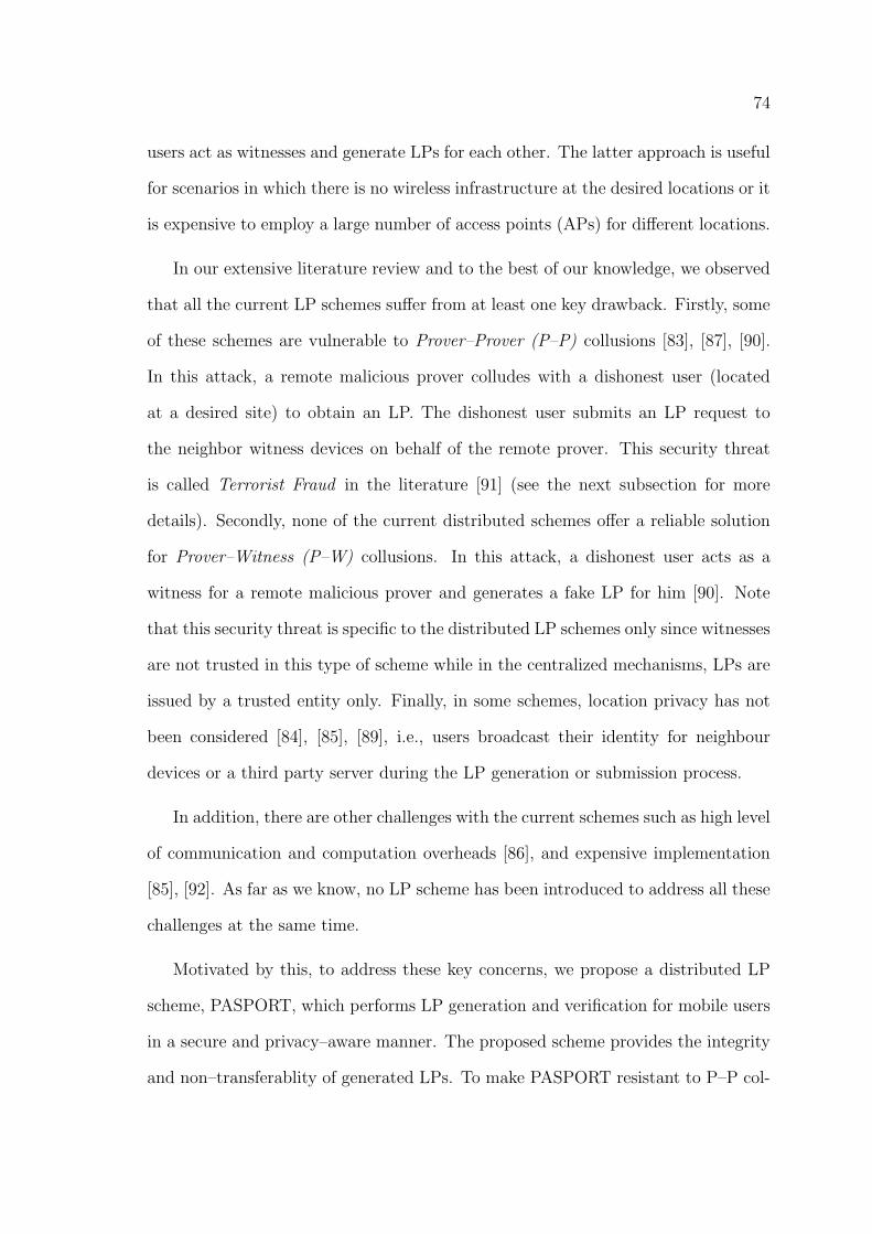
74
users act as witnesses and generate LPs for each other. The latter approach is useful
for scenarios in which there is no wireless infrastructure at the desired locations or it
is expensive to employ a large number of access points (APs) for different locations.
In our extensive literature review and to the best of our knowledge, we observed
that all the current LP schemes suffer from at least one key drawback. Firstly, some
of these schemes are vulnerable to Prover–Prover (P–P) collusions [83], [87], [90].
In this attack, a remote malicious prover colludes with a dishonest user (located
at a desired site) to obtain an LP. The dishonest user submits an LP request to
the neighbor witness devices on behalf of the remote prover. This security threat
is called Terrorist Fraud in the literature [91] (see the next subsection for more
details). Secondly, none of the current distributed schemes offer a reliable solution
for Prover–Witness (P–W) collusions. In this attack, a dishonest user acts as a
witness for a remote malicious prover and generates a fake LP for him [90]. Note
that this security threat is specific to the distributed LP schemes only since witnesses
are not trusted in this type of scheme while in the centralized mechanisms, LPs are
issued by a trusted entity only. Finally, in some schemes, location privacy has not
been considered [84], [85], [89], i.e., users broadcast their identity for neighbour
devices or a third party server during the LP generation or submission process.
In addition, there are other challenges with the current schemes such as high level
of communication and computation overheads [86], and expensive implementation
[85], [92]. As far as we know, no LP scheme has been introduced to address all these
challenges at the same time.
Motivated by this, to address these key concerns, we propose a distributed LP
scheme, PASPORT, which performs LP generation and verification for mobile users
in a secure and privacy–aware manner. The proposed scheme provides the integrity
and non–transferablity of generated LPs. To make PASPORT resistant to P–P col-
75
lusions and perform private proximity checking, we develop a privacy–aware distance
bounding (DB) protocol P–TREAD and integrate it into PASPORT. P–TREAD is
a modified version of TREAD [108], a state of the art and secure distance bounding
protocol without privacy consideration. Our customization does not affect TREAD’s
main structure and features. Thus, PASPORT benefits from its security guarantees.
By employing P–TREAD as the distance bounding mechanism, a malicious prover
colluding with an adversary can easily be impersonated by the adversary later.
Generally, users do not take such a risk by initiating a Prover–Prover collusion. In
addition, to resolve the P–W collusions issue, we propose a witness selection mecha-
nism that randomly assigns the available witnesses to the requesting provers instead
of allowing them to choose the witnesses themselves. We show that by adopting
this mechanism, a P–W collusion can be conducted with only a negligible success
probability if LBSPs create sufficient incentives for users to act as witnesses and
generate LPs for provers.
6.3 PASPORT: The Proposed Scheme
In this section, we present our proposed scheme for secure LP generation and
verification. Firstly, we present the framework and its entities. Secondly, we present
the trust and threat model which we have considered in our work. Following this,
we introduce P–TREAD. Finally, the full framework of the PASPORT scheme is
presented.
6.3.1 Architecture and Entities
The proposed system architecture is shown in Fig. 6.1. As we see, the system has
a distributed architecture and consists of three types of entities, i.e., Prover, Witness
and Verifier. A Prover is a mobile user who requires to prove his/her location to
a verifier. A Witness is the entity that accepts to issue an LP for a neighboring
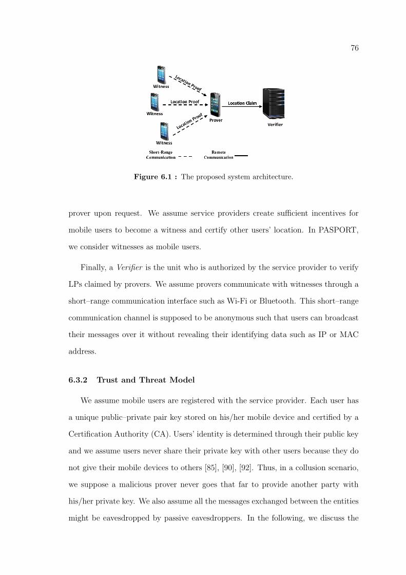
76
Figure 6.1 : The proposed system architecture.
prover upon request. We assume service providers create sufficient incentives for
mobile users to become a witness and certify other users’ location. In PASPORT,
we consider witnesses as mobile users.
Finally, a Verifier is the unit who is authorized by the service provider to verify
LPs claimed by provers. We assume provers communicate with witnesses through a
short–range communication interface such as Wi-Fi or Bluetooth. This short–range
communication channel is supposed to be anonymous such that users can broadcast
their messages over it without revealing their identifying data such as IP or MAC
address.
6.3.2 Trust and Threat Model
We assume mobile users are registered with the service provider. Each user has
a unique public–private pair key stored on his/her mobile device and certified by a
Certification Authority (CA). Users’ identity is determined through their public key
and we assume users never share their private key with other users because they do
not give their mobile devices to others [85], [90], [92]. Thus, in a collusion scenario,
we suppose a malicious prover never goes that far to provide another party with
his/her private key. We also assume all the messages exchanged between the entities
might be eavesdropped by passive eavesdroppers. In the following, we discuss the
77
trust and threat model for each entity individually.
Prover. It is assumed that the prover makes an effort to obtain false LPs. This
can be done through different scenarios in which a prover might (a) try to provide
the witnesses with fake information about his/her location to convince them to
generate LPs for him/her, (b) manipulate the LP issued for him/her to change its
location or time field, (c) attempt to steal an LP issued for another user and use
it for him/herself, and (d) collude with other users (provers or witnesses) to obtain
LPs. Moreover, we assume provers try to obtain the identity of witnesses.
Witness. A witness might collude with a prover to generate a fake LP for
him/her. In addition, a witness may try to deny an LP which has been issued
by him/herself. Witnesses are assumed to be curious about the provers’ identity.
Verifier. We suppose the verifier is trusted and never leaks users’ identity and
their spatiotemporal data. It is assumed that the verifier keeps a regularly updated
list of witnesses who are present at the given location and have accepted to generate
LPs for other users. The verifier accepts the LPs issued by these witnesses only. We
suppose service providers create necessary incentives to encourage selfish users to
collaborate with the system. Otherwise they might not generate LPs to save their
battery power or reduce their communication costs.
Regarding collusions, we consider both Prover–Prover and Prover–Witness col-
lusions in our threat model as it can be directly derived from the above assumptions.
In the next subsection, we introduce the proposed privacy–aware DB protocol P–
TREAD.
6.3.3 P–TREAD
In this subsection, we present P–TREAD, a modified version of TREAD, for
private proximity checking in the PASPORT architecture.
78
As discussed in the Preliminaries subsection, to protect users’ privacy, we need
to customize TREAD in such a way that provers can anonymously submit an LP
request to neighbor witnesses. For this reason, in P–TREAD, we limit a witness’ role
to only collecting (not verifying) the required data from the prover (the verification
is performed by the remote trusted verifier). All the privacy–sensitive data are
encrypted by the prover and sent to a witness who signs and sends them back to
the prover as an LP. Then, after the claim (received LP) is submitted to the verifier
by the prover, verification of the claim can be performed by the trusted verifier in
the next phase. We divide the whole procedure into two phases, (a) data collection
and LP generation, and (b) authentication and verification.
Phase 1. Data collection & LP generation. In this part of the protocol,
the initialization phase of TREAD is performed with the following exceptions:
• The prover device does not send IDP to the witnesses as a plain text message
(it only sends e to the witnesses).
• e is computed by the prover device using the verifier’s public key. Therefore,
the witnesses can not decrypt it and deanonymize the prover. We assume that
the verifier publishes its public key for the users. Moreover, every user has
registered a public/private key pair with the verifier.
• The witness devices do not check the prover’s signature σP since the prover
must be anonymous (in addition, they can not decrypt e and obtain the sig-
nature). Later, σP will be checked by the verifier in the next phase.
Then, the DB procedure is performed similar to the DB phase of TREAD by which
the prover’s responses ri to challenge bits ci (i = 1, 2, . . . , n) are collected. After
data collection is finished, the witness device creates the following LP and sends it
79
to the prover:
LP = EV erifier(m2||SWitness(m2))
where m2 = r||c||h||e||IDW ||Loc||time and IDW is the witness ID. Note that the
prover can not see IDW since it is encrypted using the verifier’s public key. This
preserves location privacy of the witnesses as well. Finally, the prover submits the
following message with the remote verifier:
LP′= EV erifier(LP ||a||b||IDP )
In other words, the witness collects the required information from the prover (e and
r), creates message LP , and sends it to the prover for submission. In this phase, the
witness can not see the prover’s identity as it has been encrypted by the verifier’s
public key in message e.
Phase 2. Authentication & verification. In this phase, the verifier au-
thenticates the prover based on the received LP′
and verifies the validity of the LP
issued by the witness. To do this, it first decrypts LP′
using its private key and
extracts LP , a, b, and IDP . Then, it checks the following:
• The signature σP placed in message e must match the prover’s signature based
on IDP .
• The received IDP s placed in e and LP′
must match.
• The witness signature on message m2 must match the signature associated
with IDW .
• The two a||bs placed in the messages e and LP′
must match.
• The received response r must match r′
where r′
is obtained based on the
received a, b, h, and c bit–strings.
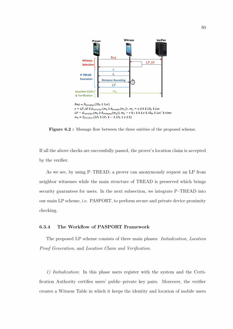
80
Figure 6.2 : Message flow between the three entities of the proposed scheme.
If all the above checks are successfully passed, the prover’s location claim is accepted
by the verifier.
As we see, by using P–TREAD, a prover can anonymously request an LP from
neighbor witnesses while the main structure of TREAD is preserved which brings
security guarantees for users. In the next subsection, we integrate P–TREAD into
our main LP scheme, i.e. PASPORT, to perform secure and private device proximity
checking.
6.3.4 The Workflow of PASPORT Framework
The proposed LP scheme consists of three main phases: Initialization, Location
Proof Generation, and Location Claim and Verification.
1) Initialization: In this phase users register with the system and the Certi-
fication Authority certifies users’ public–private key pairs. Moreover, the verifier
creates a Witness Table in which it keeps the identity and location of mobile users
81
who accept to be a witness. This table is regularly updated as witnesses sign on or
off at every site. Furthermore, for every registered user in the system, the verifier
records a list of provers for which the user generates an LP. These lists are used
by the verifier to select which witnesses are qualified to generate LPs for a specific
prover. This is done to prevent Prover–Witness collusions.
2) Location Proof Generation: This phase is run in two stages: Witness Selection
and P–TREAD Execution (see Fig. 6.2).
2.1) Witness Selection: In this stage, the prover submits an LP request to
the verifier. Upon receiving the prover’s request, the verifier selects K witnesses
form its Witness Table to generate LPs for the prover. This is done to neutralize
Prover–Witness collusions because in this case, the prover does not have control
over the witness selection process. However, to further protect PASPORT against
prover–witness collusions, we integrate an entropy–based trust model as a supple-
mentary method into the witness selection mechanism. Using this trust model, a
trust score is computed by the verifier for every available witness device w based on
its LP generation history and the number of LPs that w and the prover have issued
for each other in the past. If the obtained score is above a threshold, the device is
selected to witness for a requesting prover. The following step by step activities are
performed in this stage:
i. Prover: First, the prover sends the following message Req to the verifier to
inform it that he/she wants to start requesting an LP. This message can be
sent to the verifier through the prover’s Internet connection.
Req = EV erifier(IDP‖Loc)
ii. Verifier: Upon receiving the prover’s message, the verifier extracts all the
witnesses who have recently (in a reasonable period of time) proved that they
82
are in an acceptable distance to location Loc from its Witness Table (this
acceptable distance is defined depending on the application). Then, K wit-
nesses are selected among the shortlisted witnesses using the proposed trust
model. These K witnesses are then qualified to generate LPs for this prover.
If there are not enough qualified witnesses, the verifier suspend this request
until the necessary number of qualified witnesses become available. Then, the
verifier generates a unique ID for this LP (LP ID) and sends it to the selected
witnesses and the prover as well.
2.2) P–TREAD Execution: In this stage, the prover starts to perform the P–
TREAD protocol.
i. Prover: The prover generates two n–bit random numbers a and b, and then
computes the following message e and broadcasts it through the predefined
short–range communication interface (WiFi or Bluetooth).
e = LP ID‖EV erifier(m1‖SProver(m1)) ,
where
m1 = a‖b‖IDP‖Loc
ii. Witness: A witness upon receiving e, extracts the LP ID and compares it
with the one received from the verifier. If they are not same, it discards e.
Otherwise, it generates an n–bit random number h and sends it to the prover.
iii. Prover: The prover computes (zi = bi ⊕ hi) for i = 1, 2, . . . , n and sends an
Ack to the witness.
iv. Witness: The witness starts an n–stage time sensitive DB process by gen-
erating a random bit ci at each stage i and sending it to the prover. It also
starts a timer immediately after sending ci.
83
v. Prover: Upon receiving ci, the prover instantly sends the following response
ri to the witness:
ri = ai.c̄i + zi.ci
vi. Witness: The witness stops the timer when the response ri is received from
the prover. The timer must show a time less than the predefined threshold
2dmaxC
+ to, where dmax is the maximum allowable distance between the prover
and the witness, C is the speed of light, and tO is the overhead time required
by the prover to compute the response bit ri upon receiving ci. If all the
n responses are received in the correct time, the witness issues the following
location proof and sends it to the prover:
LP = EV erifier(m2‖SWitness(m2)) ,
where
m2 = r‖c‖h‖e‖IDW‖Loc′‖time
For timer values larger than this threshold, the witness generates the following
location proof:
LP = EV erifier(m3‖SWitness(m3)) ,
where
m3 = IDW‖reject
As we see, we adopt the sign–then–encrypt model to compute PASPORT mes-
sages. This protects the privacy of provers (witnesses). The reason is that if the
more common encrypt–then–sign model is chosen, a witness (prover) can check the
signature on e (on LP ) with the public keys of all the users and find the prover’s
(witness’) identity. Moreover, by using this method, eavesdroppers never infer the
users’ identity.
84
3) Location Proof Claim and Verification: Upon receiving LP s from all the K
witnesses, the prover concatenates them in message m4 and sends it to the verifier.
m4 = EV erifier(LP1‖LP2‖ . . . ‖LPK‖a‖b)
The verifier checks the received location proofs and either accepts or rejects the
prover’s claim. First, it decrypts each witness’s location proof and message e using
its private key. Then, it computes r′i = ai.c̄i + (bi ⊕ hi).ci for i = 1, 2, 3, . . . , n
regarding the received a, b, c, and h. If r′i 6= ri, the verifier rejects the prover’s
claim. Otherwise, the following checks are performed by the verifier:
• Is the witness with identity IDW among the witnesses which have been qual-
ified by the verifier in the Witness Selection stage?
• Are the two IDP s extracted form Req and m1 the same?
• Are prover’s and witnesses’ signatures on m1 and m2 correct regarding ID P
and IDW s respectively?
• Is Loc in an acceptable range of Loc′?
• Is time in an acceptable range of the current time?
• Are the two a‖b s received in the messages m1 and m4 the same?
• Is K −KR ≥ T correct? Where KR is the number of rejected location proofs
and T is a threshold which is defined depending on the application.
Assuming the prover’s location claim passes all the above checks successfully, the
verifier accepts the prover’s claim.
6.3.5 Witness Trust Model
To further protect PASPORT against prover–witness collusions, we integrate an
entropy–based trust model into the PASPORT witness selection mechanism. Using
85
this trust model, the verifier computes a trust score for a witness device based on
its LP generation history. If the obtained score is above a threshold, the device is
selected to witness for a requesting prover. In fact, a witness device receives a low
score if it has issued many LPs for that prover. Thus, the prover device is prevented
from receiving its LPs from a small group of witnesses only.
We adopt an entropy–based approach to measure the trust scores. In information
theory, entropy represents the average amount of information that we get from a
message produced by a stochastic source of data. It works based on the fact that
when a low–probability message is received, it carries more information than when
the source of data produces a high–probability message [120]. Thus, it is a suitable
measure of the level of diversity and randomness that a prover device should have
in the list of its witnesses. In other words, when a higher entropy is obtained for
a witness device, it is more likely that it has generated LPs for a diverse range of
provers rather than for a small group of prover devices.
Consider w is a witness device that has already issued at least one LP for N
prover devices p1, p2, . . . , pN . Assume A(w, pi) is a percentage of the past LP trans-
actions between w and pi out of w’s total past LP transactions. The entropy of w
is obtained using the following equation.
ew = −N∑i=1
A(w, pi)log(A(w, pi))
We define S(w, pi) as the trust score of device w to be selected as a witness for
the prover device pi.
S(w, pi) =ewepi
1 + B(w, pi)
where B(w, pi) is the number of LPs that w and pi have issued for each other in the
past out of their total number of LP transactions.
As a result, in the witness selection phase, the verifier selects those devices with
the highest trust score. This prevents the system from selecting a witness who may
86
have a connection with the prover and has already issued several LPs for the prover.
Moreover, using this model, possible prover–witness collusions can be detected and
prevented by the system because a prover device who has received majority of its
LPs from a small group of witnesses is more likely to collude with these witnesses.
6.3.6 PASPORT Usability
Since PASPORT has a decentralized architecture, it relies on the collaboration of
mobile users to generate location proofs for each other. Note that users usually need
to have an LP for crowded public places (e.g., shopping centers). This mitigates the
concerns about the number of available witnesses. However, mobile users may refuse
to collaborate with the system in order to save their battery power or reduce their
communication costs. To address this issue, service providers should create sufficient
incentives for mobile users to collaborate with the system and certify other users’
location. In this regard, we propose two approaches to overcome the issue.
i. Location–based service providers can incentivize mobile users to collaborate
by offering them some rewards, badges and benefits that they are currently
providing to their users (see [26] and [84] for more details and examples).
These rewards can be granted to mobile devices based on their contribution
in the network, e.g., the number of LPs that they have generated for other
users in a given time period. Moreover, other businesses such as insurance
companies and government agencies that might utilize LPs of their customers
can contribute to make the rewards more valuable. This creates the necessary
incentive for mobile users to collaborate with the system.
ii. The second approach is to integrate an incentive mechanism into the proposed
scheme, e.g., using a blockchain architecture that remunerate users with a
given amount of a cryptocurrency. Since PASPORT is a decentralized scheme,
87
the distributed architecture of blockchains is an appropriate platform to ad-
dress this issue. This encourages mobile users to collaborate with the system
and respond to other users’ LP requests.
Thus, by applying the incentive policies on the proposed scheme and encouraging
mobile users, a sufficient number of witness devices are become available for the
verifier to select.
6.4 Results
In this section, we first present our security and privacy analysis. Then, the
results of our experiments are presented and discussed.
6.4.1 Security and Privacy Analysis
We perform a comprehensive security and privacy analysis to show that PAS-
PORT achieves the necessary security and privacy properties of a secure and privacy–
aware LP scheme described in [24] and [30].
1. Resistance to Distance Frauds: In PASPORT, distance frauds are pre-
vented by the time sensitive DB process (performed in stages 2–2–d, 2–2–e and
2–2–f) which is performed via a short–range communication interface. Moreover,
the existence of the random number h ensures us that ai 6= bi⊕hi. Otherwise (if the
witness does not send h and the prover responds just with ri = ai.c̄i+bi.ci), a remote
malicious prover can simply select a = b and send ri = ai = bi before it receives the
challenge bit ci (in this case ri does not depend on the challenge bit ci). Thus, for a
remote malicious prover the only way to have his fake location verified is colluding
with a dishonest prover or witness. As we see in this section, PASPORT is resistant
to Prover–Prover collusions and reduces the success probability of Prover–Witness
collusions to a negligible value.
88
2. Unforgeability: It is not feasible for a malicious prover to create a location
proof himself without proving his location to a qualified witness. The reason is
that the verifier checks each qualified witness’ ID with their signature on m2. Since
users do not share their private key with each other, the malicious prover can not
create the witness’ signature on m2 even if he knows the identity of each qualified
witness. Moreover, an adversary who tries to forge another user’s location proof
will not be successful because he does not have the victim’s private key to sign
m1. Furthermore, if a location proof is created by a dishonest witness W′
who has
not been selected as a qualified witness, it will be easily detected by the verifier by
comparing the identity of W′
with all the qualified witnesses’ identity.
3. Non–Transferability: Suppose an adversary wants to use a location proof
which has been issued for prover P . Even if the adversary knows the prover’s ID, i.e.,
IDP , he still does not have the random numbers a and b to create m4 and submit his
claim. Note that random numbers a and b have been encrypted using the verifier’s
public key. Thus, neither the adversary nor the witness can see them. Moreover,
the presence of time in m2 makes it infeasible for the prover device P to give its
location proof along with IDP , a and b to another device for later submissions. In
this case, the prover can not change time because it has been signed by the witness’
private key and encrypted using the verifier’s public key.
4. Resistance to Mafia Frauds: Suppose an adversary A wants to perform a
Mafia Fraud on prover P and witness W who are both honest. Suppose A consists of
(or is modeled by) a witness W̄ and a prover P̄ . Even if we assume that W̄ obtains
message e by communicating with P , it is not feasible for p̄ to fool W using e. The
reason is that P̄ must successfully perform the DB process by sending response bits
ri to W . This requires the total knowledge of random numbers a and b which P
never sends them to W̄ . Moreover, A does not gain any further knowledge about
a and b by pretending to be different witnesses (for example n malicious witness
89
W̄1, W̄2, . . . , W̄n). This is because P generates different numbers a and b whenever
he/she performs P–TREAD. In other words, for different witnesses, different a‖b is
generated. Therefore, PASPORT is resistant to Mafia Frauds.
5. Resistance to Terrorist Frauds (Prover–Prover collusions): Suppose
a remote malicious prover P colludes with an adversary A which is close to an
honest witness W to obtain a fake LP. In this attack, A must send message e to
W and perform DB process on behalf of P . To perform this attack, P helps A by
generating message e and sending it to A. In addition, P has to send the random
numbers a and b to A as well. Otherwise, A can not respond to challenge bits ci
in DB process and the attack is defeated. However, if P sends a‖b to A, he can
easily impersonate P later for as many times as he wants. Therefore, the prover
must select one between performing the attack and being impersonated. In fact, in
PASPORT, the cost of a Prover–Prover collusion is increased to such a level that
no rational prover accepts its risk.
6. Resistance to Sybil Attacks: In a Sybil attack, an adversary tries to
control or influence a peer–to–peer network by creating multiple fake identities.
There are a number of countermeasures that can be adopted to make PASPORT
resistant to Sybil attacks.
i. Identity Verification: Since PASPORT is a permissioned peer–to–peer net-
work (rather than a permissionless network, e.g., Bitcoin), all users’ identities
are verified before they are authorized to access the system. This can be sup-
ported by forcing users to perform a two–factor authentication process when
they register to the network. For example, users may be asked to provide a
security code sent to their mobile phone or email address. In this case, the
network rejects to create a new account if a duplicate mobile phone number
or email address is provided by the adversary. This makes a Sybil attack
90
non–economic for malicious users since they have to provide many SIM cards
or email addresses to proceed with the attack. Alternatively, users may need
to sign up using individual email addresses or social network profiles, e.g.,
Facebook accounts. Furthermore, in a specific time interval, no more than a
specific number of accounts may be allowed to be created using a single IP
address.
ii. Unequal Reputation: A supplementary technique to prevent Sybil attacks
is to consider different levels of reputation for different accounts. Using this
technique, witness devices associated with the accounts with an older cre-
ation date receive more reputation and their testimony is highly accepted.
Newly–created accounts must remain active for a specific period before they
become eligible to witness. This limits the power of new accounts. There-
fore, creating many new accounts does not result in any advantage for a Sybil
attacker against other older reputable accounts.
iii. Cost to create an identity: To prevent malicious users from creating mul-
tiple fake accounts, the network may consider a small cost for every user that
wants to join the network. In this case, the cost to create a single account
is small. However, the total cost to create many identities is higher than the
reward or benefit that the attacker receives after successfully conducting the
Sybil attack. Note that it is more important to make it expensive for an at-
tacker to create and control multiple accounts in a short period of time rather
than just creating a new account. In other words, considering a cost for iden-
tity creation should not restrict honest users from joining the network. In
fact, the amount of cost should be selected in such a way that creating many
accounts becomes non–economic comparing to the benefits that the attacker
receives.
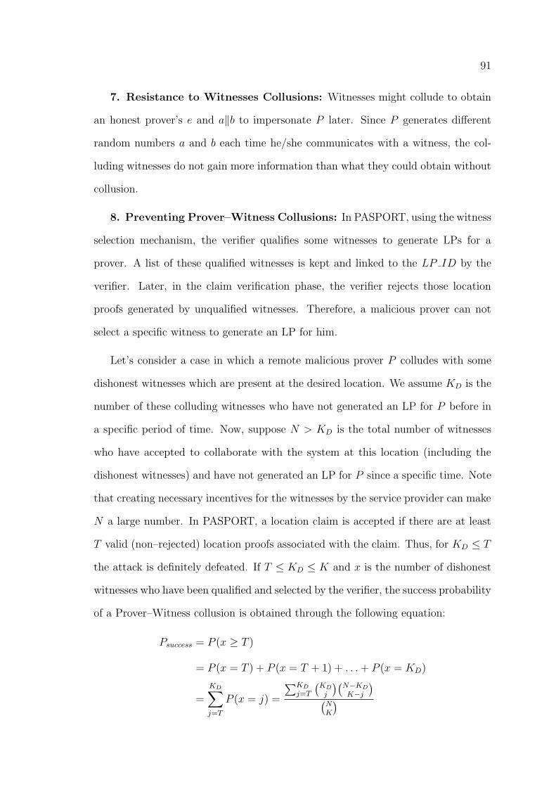
91
7. Resistance to Witnesses Collusions: Witnesses might collude to obtain
an honest prover’s e and a‖b to impersonate P later. Since P generates different
random numbers a and b each time he/she communicates with a witness, the col-
luding witnesses do not gain more information than what they could obtain without
collusion.
8. Preventing Prover–Witness Collusions: In PASPORT, using the witness
selection mechanism, the verifier qualifies some witnesses to generate LPs for a
prover. A list of these qualified witnesses is kept and linked to the LP ID by the
verifier. Later, in the claim verification phase, the verifier rejects those location
proofs generated by unqualified witnesses. Therefore, a malicious prover can not
select a specific witness to generate an LP for him.
Let’s consider a case in which a remote malicious prover P colludes with some
dishonest witnesses which are present at the desired location. We assume KD is the
number of these colluding witnesses who have not generated an LP for P before in
a specific period of time. Now, suppose N > KD is the total number of witnesses
who have accepted to collaborate with the system at this location (including the
dishonest witnesses) and have not generated an LP for P since a specific time. Note
that creating necessary incentives for the witnesses by the service provider can make
N a large number. In PASPORT, a location claim is accepted if there are at least
T valid (non–rejected) location proofs associated with the claim. Thus, for KD ≤ T
the attack is definitely defeated. If T ≤ KD ≤ K and x is the number of dishonest
witnesses who have been qualified and selected by the verifier, the success probability
of a Prover–Witness collusion is obtained through the following equation:
Psuccess = P (x ≥ T )
= P (x = T ) + P (x = T + 1) + . . .+ P (x = KD)
=
KD∑j=T
P (x = j) =
∑KDj=T
(KDj
)(N−KDK−j
)(NK
)
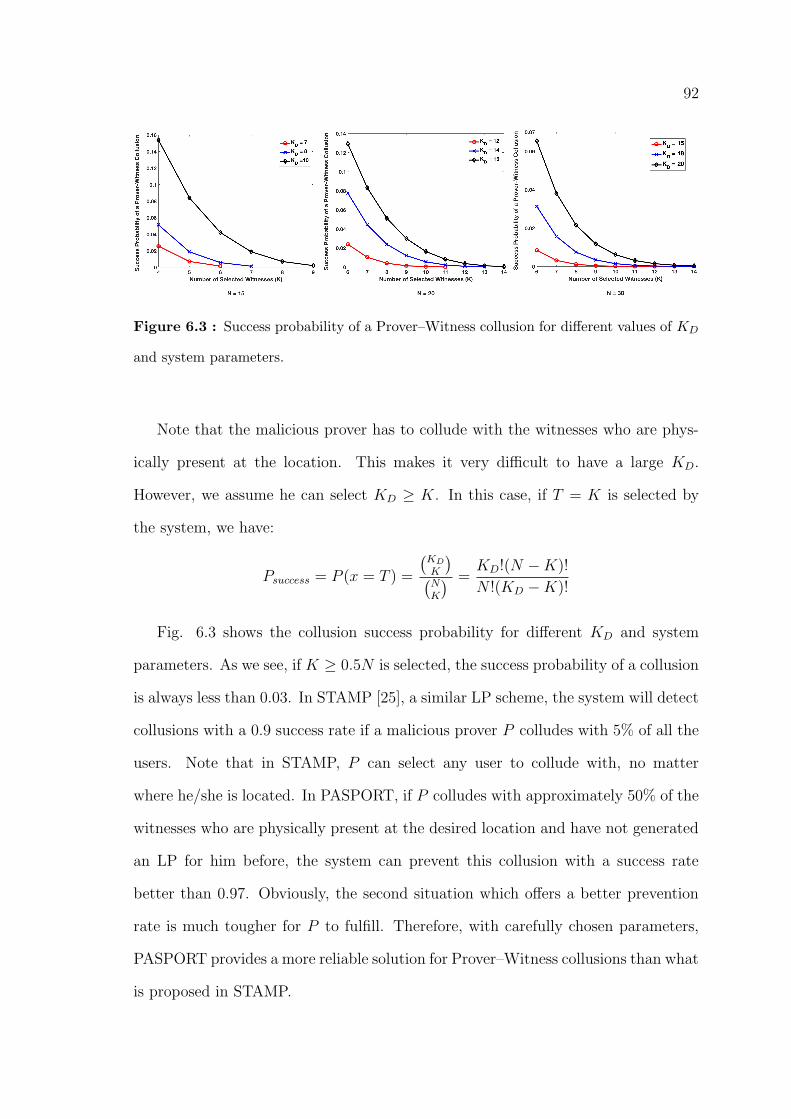
92
Figure 6.3 : Success probability of a Prover–Witness collusion for different values of KD
and system parameters.
Note that the malicious prover has to collude with the witnesses who are phys-
ically present at the location. This makes it very difficult to have a large KD.
However, we assume he can select KD ≥ K. In this case, if T = K is selected by
the system, we have:
Psuccess = P (x = T ) =
(KDK
)(NK
) =KD!(N −K)!
N !(KD −K)!
Fig. 6.3 shows the collusion success probability for different KD and system
parameters. As we see, if K ≥ 0.5N is selected, the success probability of a collusion
is always less than 0.03. In STAMP [25], a similar LP scheme, the system will detect
collusions with a 0.9 success rate if a malicious prover P colludes with 5% of all the
users. Note that in STAMP, P can select any user to collude with, no matter
where he/she is located. In PASPORT, if P colludes with approximately 50% of the
witnesses who are physically present at the desired location and have not generated
an LP for him before, the system can prevent this collusion with a success rate
better than 0.97. Obviously, the second situation which offers a better prevention
rate is much tougher for P to fulfill. Therefore, with carefully chosen parameters,
PASPORT provides a more reliable solution for Prover–Witness collusions than what
is proposed in STAMP.
93
9. Resistance to Distance Hijacking: In distance hijacking attacks [38], a
remote malicious prover H tries to fool an honest witness W on their mutual distance
by using the involuntary help of an honest prover P which is close to W . Suppose
H initiates the protocol by sending Req to the verifier. Upon receiving the related
LP ID, H must broadcast his message eH through a short–range interface but he
is not physically close enough to the qualified witnesses to do so. Thus, the attack
can not proceed. Even if we assume that H broadcasts eH for the witnesses, the
attack is defeated. The reason is that in this attack it is assumed that P responds
to W ’s challenge bits in the DB process since H is remote. However, the honest
prover P is not aware of random numbers aH and bH by which H has already created
eH . Instead, P replies to W with his/her own response bits ri computed using P ’s
random numbers aP and bP in the message eP . This causes W to generate the LP
based on eP other than eH . Therefore, if H uses the generated LP to submit his
claim with the verifier, this claim will be rejected since the signature on m1 (in
eP ) does not match with H’s identity. If H sends his aH‖bH to P beforehand, the
Distance Hijacking attack converts to a Terrorist Fraud in which P colludes with the
remote malicious prover. As we discussed before, PASPORT is resistant to Terrorist
Frauds as well.
10. Prover Location Privacy: The prover’s ID appears in messages Req,
m1 and m4. These messages are encrypted by the verifier’s public key. Thus, the
verifier is the only entity who can identify the prover and neither the witnesses nor an
eavesdropper can see the prover’s ID. As we discussed before, the sign–then–encrypt
model improves PASPORT’s ability to preserve user’s location privacy.
11. Witness Location Privacy: Since a witness device encrypts its ID using
the verifier’s public key, it is not feasible for the prover or an eavesdropper to identify
the witness. Also, users’ signatures do not reveal their identity because of the
employed sign–then–encrypt model.
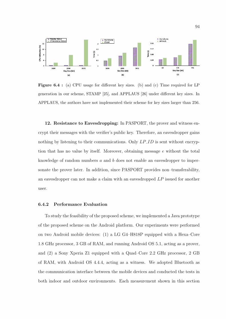
94
Figure 6.4 : (a) CPU usage for different key sizes. (b) and (c) Time required for LP
generation in our scheme, STAMP [25], and APPLAUS [26] under different key sizes. In
APPLAUS, the authors have not implemented their scheme for key sizes larger than 256.
12. Resistance to Eavesdropping: In PASPORT, the prover and witness en-
crypt their messages with the verifier’s public key. Therefore, an eavesdropper gains
nothing by listening to their communications. Only LP ID is sent without encryp-
tion that has no value by itself. Moreover, obtaining message e without the total
knowledge of random numbers a and b does not enable an eavesdropper to imper-
sonate the prover later. In addition, since PASPORT provides non–transferability,
an eavesdropper can not make a claim with an eavesdropped LP issued for another
user.
6.4.2 Performance Evaluation
To study the feasibility of the proposed scheme, we implemented a Java prototype
of the proposed scheme on the Android platform. Our experiments were performed
on two Android mobile devices: (1) a LG G4–H818P equipped with a Hexa–Core
1.8 GHz processor, 3 GB of RAM, and running Android OS 5.1, acting as a prover,
and (2) a Sony Xperia Z1 equipped with a Quad–Core 2.2 GHz processor, 2 GB
of RAM, with Android OS 4.4.4, acting as a witness. We adopted Bluetooth as
the communication interface between the mobile devices and conducted the tests in
both indoor and outdoor environments. Each measurement shown in this section
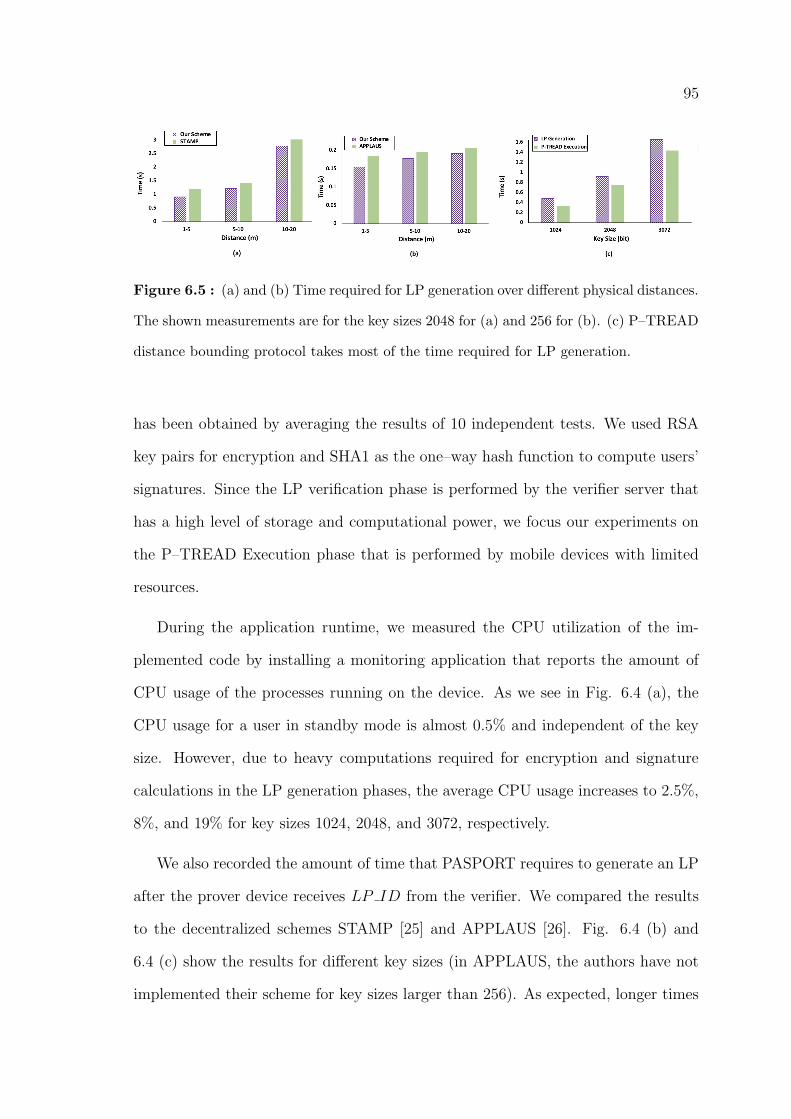
95
Figure 6.5 : (a) and (b) Time required for LP generation over different physical distances.
The shown measurements are for the key sizes 2048 for (a) and 256 for (b). (c) P–TREAD
distance bounding protocol takes most of the time required for LP generation.
has been obtained by averaging the results of 10 independent tests. We used RSA
key pairs for encryption and SHA1 as the one–way hash function to compute users’
signatures. Since the LP verification phase is performed by the verifier server that
has a high level of storage and computational power, we focus our experiments on
the P–TREAD Execution phase that is performed by mobile devices with limited
resources.
During the application runtime, we measured the CPU utilization of the im-
plemented code by installing a monitoring application that reports the amount of
CPU usage of the processes running on the device. As we see in Fig. 6.4 (a), the
CPU usage for a user in standby mode is almost 0.5% and independent of the key
size. However, due to heavy computations required for encryption and signature
calculations in the LP generation phases, the average CPU usage increases to 2.5%,
8%, and 19% for key sizes 1024, 2048, and 3072, respectively.
We also recorded the amount of time that PASPORT requires to generate an LP
after the prover device receives LP ID from the verifier. We compared the results
to the decentralized schemes STAMP [25] and APPLAUS [26]. Fig. 6.4 (b) and
6.4 (c) show the results for different key sizes (in APPLAUS, the authors have not
implemented their scheme for key sizes larger than 256). As expected, longer times
96
were recorded for larger key sizes. The reason is that the DB phase is performed for
n challenge bits. Thus, for larger values of n, it takes longer for the DB phase to be
performed. As the figures show, PASPORT provides faster responses than similar
schemes. The reason is that in STAMP and APPLAUS, the Bussard–Bagga DB
protocol is used for provers’ proximity checking while in PASPORT, we integrate
P–TREAD into the scheme to perform this job that is a more lightweight protocol
regardless of its security advantages over the Bussard–Bagga protocol. Unlike P–
TREAD, in the Bussard–Bagga protocol, different commitment and decommitment
computations are needed to be performed by the prover and witness devices, respec-
tively. Moreover, STAMP requires to perform at least two commitment calculations
in order to provide location privacy [25]. In APPLAUS, to preserve users’ location
privacy, they need to select a set of M pseudonyms and change them periodically.
This creates a high level of computation and communication overhead.
To evaluate the impact of physical distance between the mobile users on LP
generation, we conduct our experiments for different distances and compare the
results to the performance of STAMP and APPLAUS (see Fig. 6.5 (a) and 6.5 (b),
respectively). As we see, for longer distances, the required time for PASPORT to
generate an LP increases since higher communication latencies occurring in this case.
Note that distance only affects the Bluetooth communication latency and does not
change the amount of time required for computations performed in mobile devices.
Finally, Fig. 6.5 (c) shows what percentage of the time required for LP generation
is taken by the P–TREAD Execution phase. As we see, most of this time is taken by
the DB protocol since it requires multiple Bluetooth transmissions. As we discussed
before, this time is increased for larger key sizes. As a result, the selection of key
size has a critical impact on the scheme’s performance. Although larger key sizes
provide stronger security, they impose more computational and storage overheads.
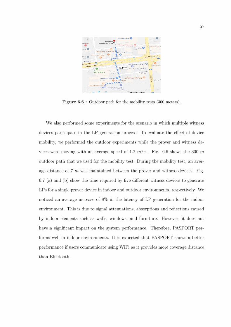
97
Figure 6.6 : Outdoor path for the mobility tests (300 meters).
We also performed some experiments for the scenario in which multiple witness
devices participate in the LP generation process. To evaluate the effect of device
mobility, we performed the outdoor experiments while the prover and witness de-
vices were moving with an average speed of 1.2 m/s . Fig. 6.6 shows the 300 m
outdoor path that we used for the mobility test. During the mobility test, an aver-
age distance of 7 m was maintained between the prover and witness devices. Fig.
6.7 (a) and (b) show the time required by five different witness devices to generate
LPs for a single prover device in indoor and outdoor environments, respectively. We
noticed an average increase of 8% in the latency of LP generation for the indoor
environment. This is due to signal attenuations, absorptions and reflections caused
by indoor elements such as walls, windows, and furniture. However, it does not
have a significant impact on the system performance. Therefore, PASPORT per-
forms well in indoor environments. It is expected that PASPORT shows a better
performance if users communicate using WiFi as it provides more coverage distance
than Bluetooth.
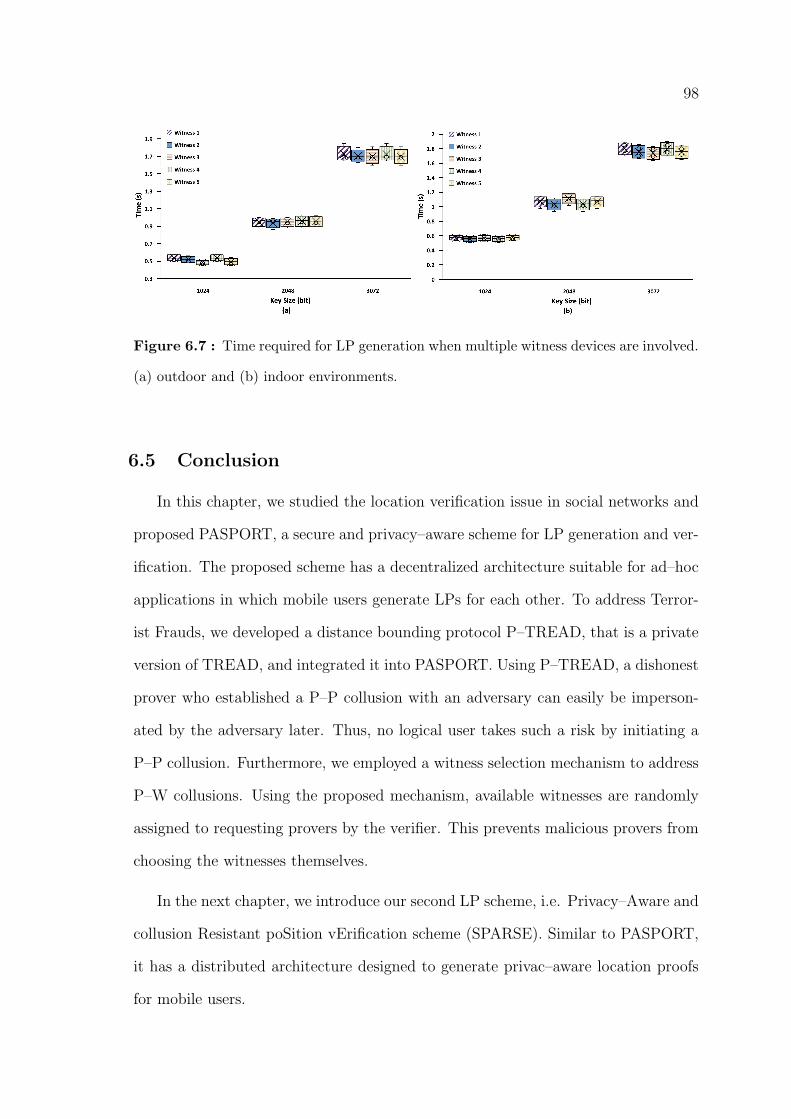
98
Figure 6.7 : Time required for LP generation when multiple witness devices are involved.
(a) outdoor and (b) indoor environments.
6.5 Conclusion
In this chapter, we studied the location verification issue in social networks and
proposed PASPORT, a secure and privacy–aware scheme for LP generation and ver-
ification. The proposed scheme has a decentralized architecture suitable for ad–hoc
applications in which mobile users generate LPs for each other. To address Terror-
ist Frauds, we developed a distance bounding protocol P–TREAD, that is a private
version of TREAD, and integrated it into PASPORT. Using P–TREAD, a dishonest
prover who established a P–P collusion with an adversary can easily be imperson-
ated by the adversary later. Thus, no logical user takes such a risk by initiating a
P–P collusion. Furthermore, we employed a witness selection mechanism to address
P–W collusions. Using the proposed mechanism, available witnesses are randomly
assigned to requesting provers by the verifier. This prevents malicious provers from
choosing the witnesses themselves.
In the next chapter, we introduce our second LP scheme, i.e. Privacy–Aware and
collusion Resistant poSition vErification scheme (SPARSE). Similar to PASPORT,
it has a distributed architecture designed to generate privac–aware location proofs
for mobile users.
99
Chapter 7
SPARSE: Privacy–Aware and Collusion Resistant
Location Proof Generation and Verification
7.1 Introduction
In this chapter, we propose the Secure, Privacy–Aware and collusion Resistant
poSition vErification scheme (SPARSE) which provides secure and private LP gen-
eration and verification for mobile users. SPARSE has a distributed architecture
designed for ad–hoc scenarios in which mobile users generate location proofs for
each other. In the proposed scheme, we do not employ a DB protocol for protec-
tion against Terrorist Fraud. Instead we adopt a time–limited approach to make
SPARSE resistant to these attacks. This introduces two advantages. Firstly, the
speed of LP generation becomes independent of the length of the users’ private key.
Secondly, the costs of the system implementation is reduced since implementing
a DB protocol requires some hardware changes on mobile devices [85]. Moreover,
to address Prover–Witness collusions, we do not allow provers to choose their wit-
nesses. Instead, the system performs a witness selection mechanism by which some
witnesses are chosen and qualified to generate LPs for a specific prover. We show
that by using this method, if the service provider creates necessary incentives for
users to collaborate with the system and generate LP for each other, the success
probability of these collusions is negligible.
Since we do not integrate any distance bounding protocol into SPARSE, it be-
comes an easy–to–implement scheme in which the location proof generation process
is independent of the length of the users’ private key. We provide a comprehensive
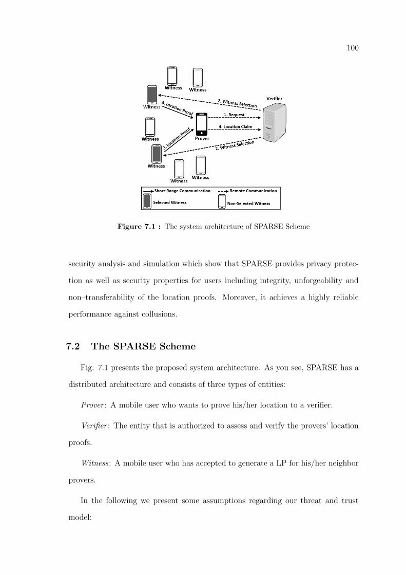
100
Figure 7.1 : The system architecture of SPARSE Scheme
security analysis and simulation which show that SPARSE provides privacy protec-
tion as well as security properties for users including integrity, unforgeability and
non–transferability of the location proofs. Moreover, it achieves a highly reliable
performance against collusions.
7.2 The SPARSE Scheme
Fig. 7.1 presents the proposed system architecture. As you see, SPARSE has a
distributed architecture and consists of three types of entities:
Prover : A mobile user who wants to prove his/her location to a verifier.
Verifier : The entity that is authorized to assess and verify the provers’ location
proofs.
Witness : A mobile user who has accepted to generate a LP for his/her neighbor
provers.
In the following we present some assumptions regarding our threat and trust
model:
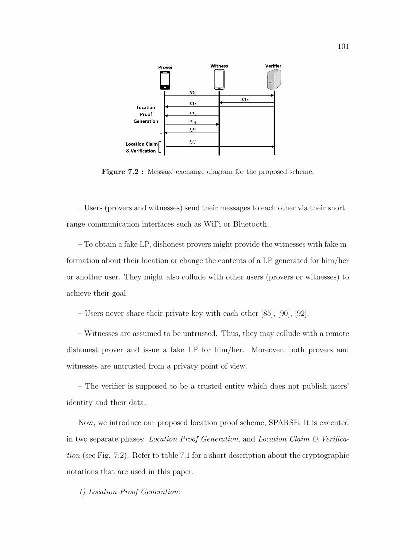
101
Figure 7.2 : Message exchange diagram for the proposed scheme.
– Users (provers and witnesses) send their messages to each other via their short–
range communication interfaces such as WiFi or Bluetooth.
– To obtain a fake LP, dishonest provers might provide the witnesses with fake in-
formation about their location or change the contents of a LP generated for him/her
or another user. They might also collude with other users (provers or witnesses) to
achieve their goal.
– Users never share their private key with each other [85], [90], [92].
– Witnesses are assumed to be untrusted. Thus, they may collude with a remote
dishonest prover and issue a fake LP for him/her. Moreover, both provers and
witnesses are untrusted from a privacy point of view.
– The verifier is supposed to be a trusted entity which does not publish users’
identity and their data.
Now, we introduce our proposed location proof scheme, SPARSE. It is executed
in two separate phases: Location Proof Generation, and Location Claim & Verifica-
tion (see Fig. 7.2). Refer to table 7.1 for a short description about the cryptographic
notations that are used in this paper.
1) Location Proof Generation:
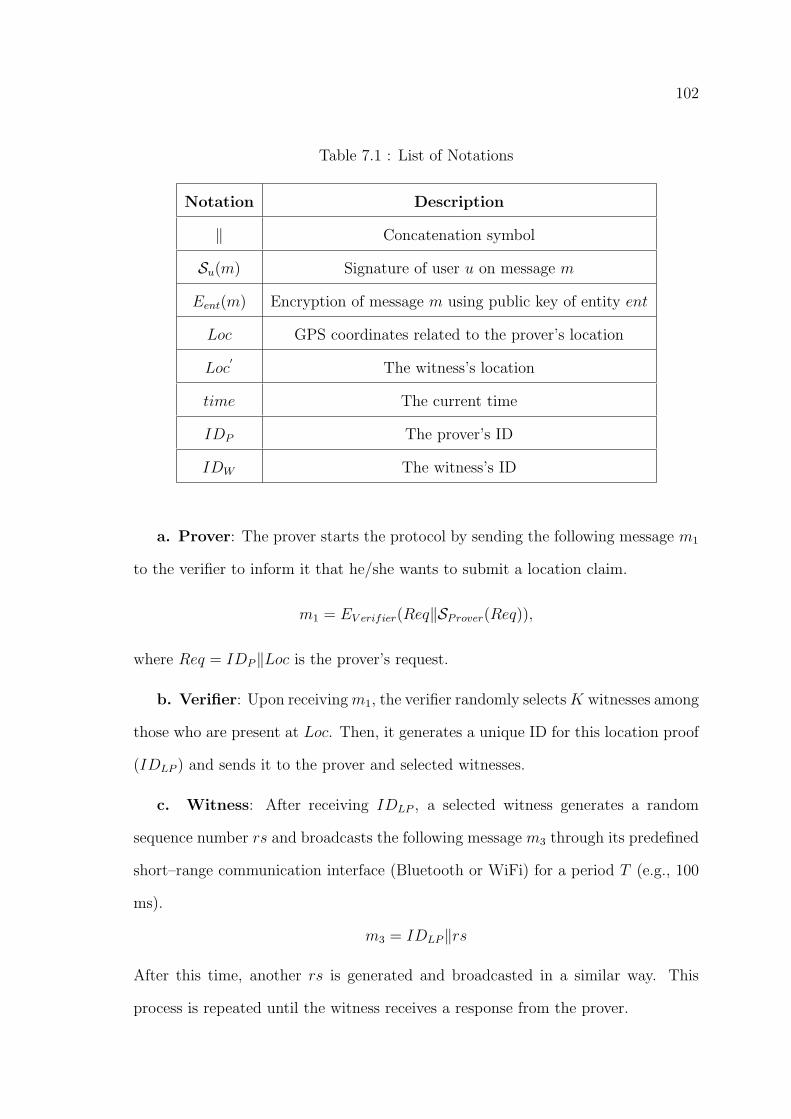
102
Table 7.1 : List of Notations
Notation Description
‖ Concatenation symbol
Su(m) Signature of user u on message m
Eent(m) Encryption of message m using public key of entity ent
Loc GPS coordinates related to the prover’s location
Loc′
The witness’s location
time The current time
IDP The prover’s ID
IDW The witness’s ID
a. Prover: The prover starts the protocol by sending the following message m1
to the verifier to inform it that he/she wants to submit a location claim.
m1 = EV erifier(Req‖SProver(Req)),
where Req = IDP‖Loc is the prover’s request.
b. Verifier: Upon receivingm1, the verifier randomly selects K witnesses among
those who are present at Loc. Then, it generates a unique ID for this location proof
(IDLP ) and sends it to the prover and selected witnesses.
c. Witness: After receiving IDLP , a selected witness generates a random
sequence number rs and broadcasts the following message m3 through its predefined
short–range communication interface (Bluetooth or WiFi) for a period T (e.g., 100
ms).
m3 = IDLP‖rs
After this time, another rs is generated and broadcasted in a similar way. This
process is repeated until the witness receives a response from the prover.
103
d. Prover: When the prover device receives m3, it first ensures that the IDLP is
the same as the one already received from the verifier. Otherwise, it just discards m3
and continues to listen to the channel. If they are same, the prover must immediately
compute message m4 and send it to the witness:
m4 = IDLP‖rs‖EV erifier(rs‖SProver(rs))
e. Witness: Upon receiving m4, provided that the IDLP in m4 is the same as
the current location proof ID, the witness checks to see whether this rs is the last
sequence number that had been broadcasted by itself. If it is, the witness generates
the following location proof LP and sends it to the prover.
LP = EV erifier(m5‖SWitness(m5)),
where m5 = m4‖Loc′‖time‖IDW . Otherwise, the following null LP is sent to the
prover:
LP = EV erifier(m5‖SWitness(m5)),
where m5 = null‖IDW .
2) Location Claim & Verification:
a. Prover: The prover generates the following location claim LC using the K
received LP s from the K selected witnesses and submits it with the verifier:
LC = EV erifier(m6‖SProver(m6)),
where m6 = LP1‖LP2‖ . . . ‖LPK‖IDP .
b. Verifier: After the verifier receives the LC, it checks the following items:
• Are the two IDP s received through messages m1 and LC the same?
• Is the prover’s signature on m6 correct regarding the claimed IDP ?
104
• For each LPi, (i = 1, . . . , K):
– Is the witness with identity IDW among the selected witnesses?
– Is the witness signature on m5 correct regarding the IDW ?
– Are time and Loc in an acceptable range of the current time and Loc′respectively?
– Are the two random sequences rs in m4 same?
• Is the number of non–null LPs greater than a predefined threshold KT ?
If all the above checks are passed successfully, the verifier accepts this LC. Otherwise,
the prover’s claim is rejected.
7.3 Results
This section presents our security and privacy analysis and discisses the results
of our experiments.
7.3.1 Security and Privacy Analysis
In this section, a comprehensive security and privacy analysis is presented to
show that SPARSE achieves the fundamental security and privacy properties of a
secure and privacy–aware location proof system described in [87], [88] and [92].
Resistance to Distance Frauds: In a distance fraud, a malicious prover tries
to convince an honest witness (or a verifier) that his physical distance to the witness
(or verifier) is less than what it really is. In SPARSE, the prover must sign and
encrypt the random sequence rs in a limited time T over a short–range communi-
cation interface. If a malicious prover is not located in the communication range of
the witness, he/she can not proceed with the attack. Thus, for him/her the only
way to get the fake location verified is to collude with another user. In this section,
we analyze the SPARSE performance against collusions separately.
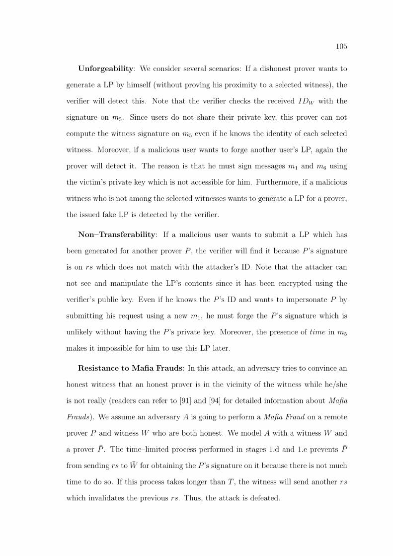
105
Unforgeability: We consider several scenarios: If a dishonest prover wants to
generate a LP by himself (without proving his proximity to a selected witness), the
verifier will detect this. Note that the verifier checks the received IDW with the
signature on m5. Since users do not share their private key, this prover can not
compute the witness signature on m5 even if he knows the identity of each selected
witness. Moreover, if a malicious user wants to forge another user’s LP, again the
prover will detect it. The reason is that he must sign messages m1 and m6 using
the victim’s private key which is not accessible for him. Furthermore, if a malicious
witness who is not among the selected witnesses wants to generate a LP for a prover,
the issued fake LP is detected by the verifier.
Non–Transferability: If a malicious user wants to submit a LP which has
been generated for another prover P , the verifier will find it because P ’s signature
is on rs which does not match with the attacker’s ID. Note that the attacker can
not see and manipulate the LP’s contents since it has been encrypted using the
verifier’s public key. Even if he knows the P ’s ID and wants to impersonate P by
submitting his request using a new m1, he must forge the P ’s signature which is
unlikely without having the P ’s private key. Moreover, the presence of time in m5
makes it impossible for him to use this LP later.
Resistance to Mafia Frauds: In this attack, an adversary tries to convince an
honest witness that an honest prover is in the vicinity of the witness while he/she
is not really (readers can refer to [91] and [94] for detailed information about Mafia
Frauds). We assume an adversary A is going to perform a Mafia Fraud on a remote
prover P and witness W who are both honest. We model A with a witness W̄ and
a prover P̄ . The time–limited process performed in stages 1.d and 1.e prevents P̄
from sending rs to W̄ for obtaining the P ’s signature on it because there is not much
time to do so. If this process takes longer than T , the witness will send another rs
which invalidates the previous rs. Thus, the attack is defeated.
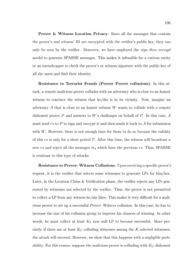
106
Prover & Witness Location Privacy: Since all the messages that contain
the prover’s and witness’ ID are encrypted with the verifier’s public key, they can
only be seen by the verifier. Moreover, we have employed the sign–then–encrypt
model to generate SPARSE messages. This makes it infeasible for a curious entity
or an eavesdropper to check the prover’s or witness signature with the public key of
all the users and find their identity.
Resistance to Terrorist Frauds (Prover–Prover collusions): In this at-
tack, a remote malicious prover colludes with an adversary who is close to an honest
witness to convince the witness that he/she is in its vicinity. Now, imagine an
adversary A that is close to an honest witness W wants to collude with a remote
dishonest prover P and answers to W ’s challenges on behalf of P . In this case, A
must send rs to P to sign and encrypt it and then sends it back to A for submission
with W . However, there is not enough time for them to do so because the validity
of this rs is only for a short period T . After this time, the witness will broadcast a
new rs and reject all the messages m4 which have the previous rs. Thus, SPARSE
is resistant to this type of attacks.
Resistance to Prover–Witness Collusions: Upon receiving a specific prover’s
request, it is the verifier that selects some witnesses to generate LPs for him/her.
Later, in the Location Claim & Verification phase, the verifier rejects any LPs gen-
erated by witnesses not selected by the verifier. Thus, the prover is not permitted
to collect a LP from any witness he/she likes. This makes it very difficult for a mali-
cious prover to set up a successful Prover–Witness collusion. In this case, he has to
increase the size of his collusion group to improve his chances of winning. In other
words, he must collect at least KT non–null LP to become successful. More pre-
cisely, if there are at least KT colluding witnesses among the K selected witnesses,
the attack will succeed. However, we show that this happens with a negligible prob-
ability. For this reason, suppose the malicious prover is colluding with KC dishonest
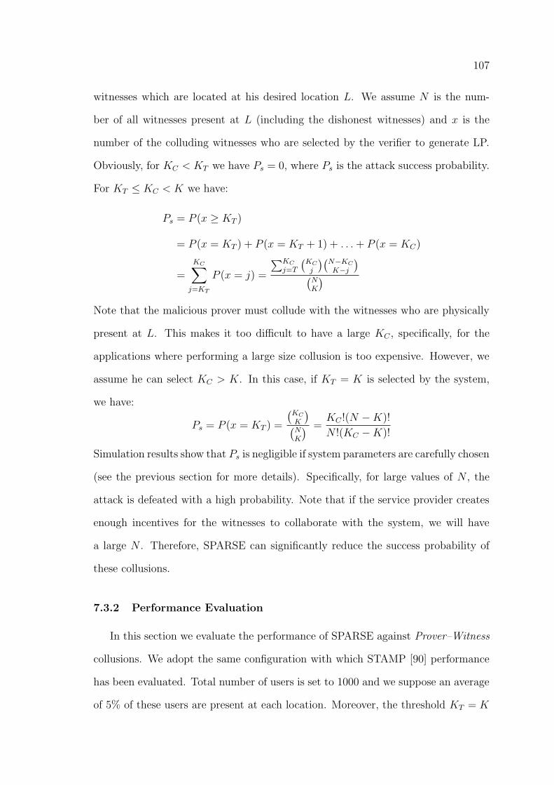
107
witnesses which are located at his desired location L. We assume N is the num-
ber of all witnesses present at L (including the dishonest witnesses) and x is the
number of the colluding witnesses who are selected by the verifier to generate LP.
Obviously, for KC < KT we have Ps = 0, where Ps is the attack success probability.
For KT ≤ KC < K we have:
Ps = P (x ≥ KT )
= P (x = KT ) + P (x = KT + 1) + . . .+ P (x = KC)
=
KC∑j=KT
P (x = j) =
∑KCj=T
(KCj
)(N−KCK−j
)(NK
)Note that the malicious prover must collude with the witnesses who are physically
present at L. This makes it too difficult to have a large KC , specifically, for the
applications where performing a large size collusion is too expensive. However, we
assume he can select KC > K. In this case, if KT = K is selected by the system,
we have:
Ps = P (x = KT ) =
(KCK
)(NK
) =KC !(N −K)!
N !(KC −K)!
Simulation results show that Ps is negligible if system parameters are carefully chosen
(see the previous section for more details). Specifically, for large values of N , the
attack is defeated with a high probability. Note that if the service provider creates
enough incentives for the witnesses to collaborate with the system, we will have
a large N . Therefore, SPARSE can significantly reduce the success probability of
these collusions.
7.3.2 Performance Evaluation
In this section we evaluate the performance of SPARSE against Prover–Witness
collusions. We adopt the same configuration with which STAMP [90] performance
has been evaluated. Total number of users is set to 1000 and we suppose an average
of 5% of these users are present at each location. Moreover, the threshold KT = K
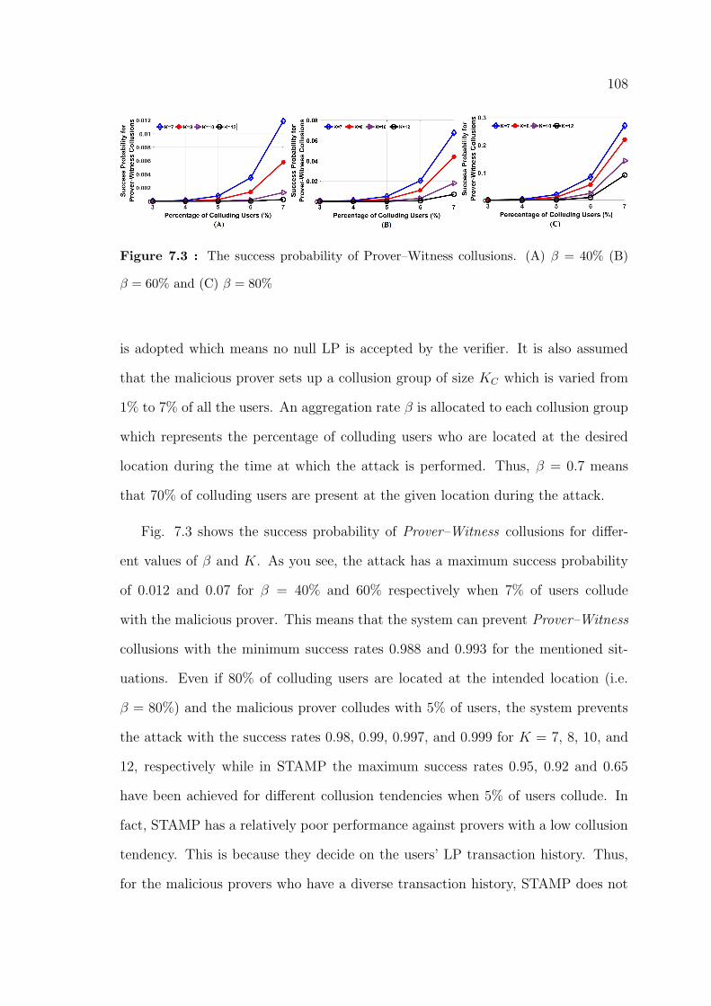
108
Figure 7.3 : The success probability of Prover–Witness collusions. (A) β = 40% (B)
β = 60% and (C) β = 80%
is adopted which means no null LP is accepted by the verifier. It is also assumed
that the malicious prover sets up a collusion group of size KC which is varied from
1% to 7% of all the users. An aggregation rate β is allocated to each collusion group
which represents the percentage of colluding users who are located at the desired
location during the time at which the attack is performed. Thus, β = 0.7 means
that 70% of colluding users are present at the given location during the attack.
Fig. 7.3 shows the success probability of Prover–Witness collusions for differ-
ent values of β and K. As you see, the attack has a maximum success probability
of 0.012 and 0.07 for β = 40% and 60% respectively when 7% of users collude
with the malicious prover. This means that the system can prevent Prover–Witness
collusions with the minimum success rates 0.988 and 0.993 for the mentioned sit-
uations. Even if 80% of colluding users are located at the intended location (i.e.
β = 80%) and the malicious prover colludes with 5% of users, the system prevents
the attack with the success rates 0.98, 0.99, 0.997, and 0.999 for K = 7, 8, 10, and
12, respectively while in STAMP the maximum success rates 0.95, 0.92 and 0.65
have been achieved for different collusion tendencies when 5% of users collude. In
fact, STAMP has a relatively poor performance against provers with a low collusion
tendency. This is because they decide on the users’ LP transaction history. Thus,
for the malicious provers who have a diverse transaction history, STAMP does not
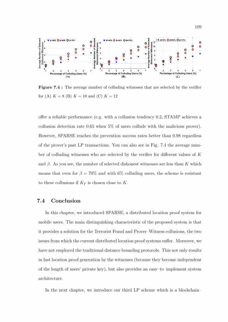
109
Figure 7.4 : The average number of colluding witnesses that are selected by the verifier
for (A) K = 8 (B) K = 10 and (C) K = 12
offer a reliable performance (e.g. with a collusion tendency 0.2, STAMP achieves a
collusion detection rate 0.65 when 5% of users collude with the malicious prover).
However, SPARSE reaches the prevention success rates better than 0.98 regardless
of the prover’s past LP transactions. You can also see in Fig. 7.4 the average num-
ber of colluding witnesses who are selected by the verifier for different values of K
and β. As you see, the number of selected dishonest witnesses are less than K which
means that even for β = 70% and with 6% colluding users, the scheme is resistant
to these collusions if KT is chosen close to K.
7.4 Conclusion
In this chapter, we introduced SPARSE, a distributed location proof system for
mobile users. The main distinguishing characteristic of the proposed system is that
it provides a solution for the Terrorist Fraud and Prover–Witness collusions, the two
issues from which the current distributed location proof systems suffer. Moreover, we
have not employed the traditional distance bounding protocols. This not only results
in fast location proof generation by the witnesses (because they become independent
of the length of users’ private key), but also provides an easy–to–implement system
architecture.
In the next chapter, we introduce our third LP scheme which is a blockchain–

110
based scheme for location proof generation and verification. It utilises the unique
features of the blockchain technology to provide a decentralized secure and privacy–
aware scheme for location proof generation and verification.
111
Chapter 8
Blockchain for Secure Location Verification
8.1 Introduction
In this section, we utilise the unique features of the blockchain technology to
design a decentralized scheme for location proof generation and verification. In the
proposed scheme, a user who needs a location proof (called a prover) broadcasts
a request to the neighbor devices through a short–range communication interface,
e.g. Bluetooth. Those neighbor devices that decide to respond (called witnesses)
start to authenticate the requesting user. In the proposed scheme, mobile users act
as witnesses for a user (prover) that requests an LP in their physical proximity.
Witnesses start to authenticate the prover and if the prover is successfully authen-
ticated, a transaction is created based on the proposed blockchain framework. The
transaction (that holds the prover’s LP data) is then broadcast onto a peer–to–peer
network over the internet where it can be picked up by verifiers for further verifi-
cation. Finally, the verified transaction is stored in a time–stamped public ledger
accessible for LBSPs. To preserve users’ location privacy, they cryptographically
commit to their spatiotemporal data before it is inserted into a transaction. Later,
they open the commitment when they submit a location claim with an LBSP.
To prevent distance frauds, all the communications between prover and witness
devices are performed through a short–range communication interface like Blue-
tooth. Moreover, we integrate an incentive mechanism into the proposed scheme
whereby witnesses and verifiers are rewarded by a small amount of cryptocurrency.
This incetivizes them to collaborate with the system rather than ignoring provers’
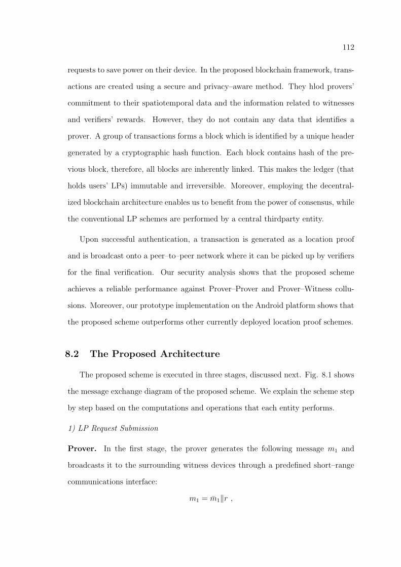
112
requests to save power on their device. In the proposed blockchain framework, trans-
actions are created using a secure and privacy–aware method. They hlod provers’
commitment to their spatiotemporal data and the information related to witnesses
and verifiers’ rewards. However, they do not contain any data that identifies a
prover. A group of transactions forms a block which is identified by a unique header
generated by a cryptographic hash function. Each block contains hash of the pre-
vious block, therefore, all blocks are inherently linked. This makes the ledger (that
holds users’ LPs) immutable and irreversible. Moreover, employing the decentral-
ized blockchain architecture enables us to benefit from the power of consensus, while
the conventional LP schemes are performed by a central thirdparty entity.
Upon successful authentication, a transaction is generated as a location proof
and is broadcast onto a peer–to–peer network where it can be picked up by verifiers
for the final verification. Our security analysis shows that the proposed scheme
achieves a reliable performance against Prover–Prover and Prover–Witness collu-
sions. Moreover, our prototype implementation on the Android platform shows that
the proposed scheme outperforms other currently deployed location proof schemes.
8.2 The Proposed Architecture
The proposed scheme is executed in three stages, discussed next. Fig. 8.1 shows
the message exchange diagram of the proposed scheme. We explain the scheme step
by step based on the computations and operations that each entity performs.
1) LP Request Submission
Prover. In the first stage, the prover generates the following message m1 and
broadcasts it to the surrounding witness devices through a predefined short–range
communications interface:
m1 = m̄1‖r ,
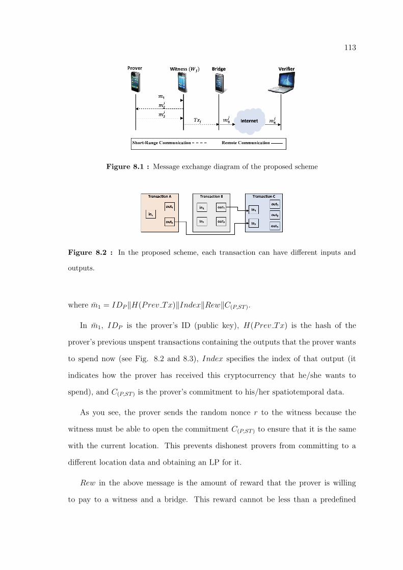
113
Figure 8.1 : Message exchange diagram of the proposed scheme
Figure 8.2 : In the proposed scheme, each transaction can have different inputs and
outputs.
where m̄1 = IDP‖H(Prev Tx)‖Index‖Rew‖C(P,ST ).
In m̄1, IDP is the prover’s ID (public key), H(Prev Tx) is the hash of the
prover’s previous unspent transactions containing the outputs that the prover wants
to spend now (see Fig. 8.2 and 8.3), Index specifies the index of that output (it
indicates how the prover has received this cryptocurrency that he/she wants to
spend), and C(P,ST ) is the prover’s commitment to his/her spatiotemporal data.
As you see, the prover sends the random nonce r to the witness because the
witness must be able to open the commitment C(P,ST ) to ensure that it is the same
with the current location. This prevents dishonest provers from committing to a
different location data and obtaining an LP for it.
Rew in the above message is the amount of reward that the prover is willing
to pay to a witness and a bridge. This reward cannot be less than a predefined
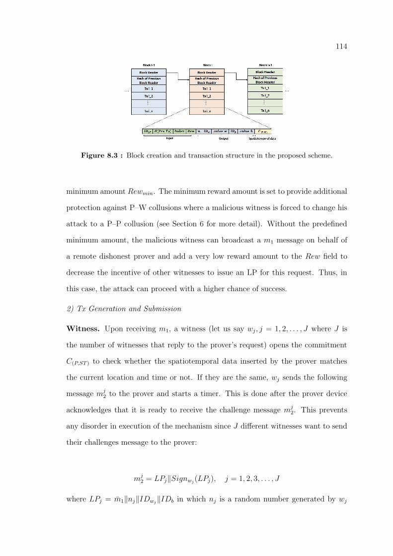
114
Figure 8.3 : Block creation and transaction structure in the proposed scheme.
minimum amount Rewmin. The minimum reward amount is set to provide additional
protection against P–W collusions where a malicious witness is forced to change his
attack to a P–P collusion (see Section 6 for more detail). Without the predefined
minimum amount, the malicious witness can broadcast a m1 message on behalf of
a remote dishonest prover and add a very low reward amount to the Rew field to
decrease the incentive of other witnesses to issue an LP for this request. Thus, in
this case, the attack can proceed with a higher chance of success.
2) Tx Generation and Submission
Witness. Upon receiving m1, a witness (let us say wj, j = 1, 2, . . . , J where J is
the number of witnesses that reply to the prover’s request) opens the commitment
C(P,ST ) to check whether the spatiotemporal data inserted by the prover matches
the current location and time or not. If they are the same, wj sends the following
message mj2 to the prover and starts a timer. This is done after the prover device
acknowledges that it is ready to receive the challenge message mj2. This prevents
any disorder in execution of the mechanism since J different witnesses want to send
their challenges message to the prover:
mj2 = LPj‖Signwj(LPj), j = 1, 2, 3, . . . , J
where LPj = m̄1‖nj‖IDwj‖IDb in which nj is a random number generated by wj
115
IDwj and IDb are the identity of the witness and selected bridge, respectively. Note
that each device knows the ID of the currently serving bridge that has been elected
by users.
Prover. When the prover device receives each mj2, it immediately signs it using its
private key and sends the following message mj3 to wj:
mj3 = mj
2‖SignP (mj2)‖ j = 1, 2, 3, . . . , J
By signing mj2 (which is an LP), the prover consents that he/she rewards Rew to
the witness, selected bridge, and verifier. For simplicity, we assume their share is
equal, however this assumption can be removed by adding two fields value w and
value b next to the IDwj and IDb respectively, to specify their share. The difference
between Rew and value w + value b is considered as the verifier’s reward (same as
the payment mechanism in Bitcoin).
Witness. Upon receiving mj3, witness wj stops the timer and checks to see whether
it was received in the predefined period of time T . T is a system parameter and
must be carefully designed such that it only provides the prover with an opportunity
to sign mj2, and send it back to wj (in the next section, we propose some practical
values for T based on our experimental results). Thus, with a carefully selected T ,
in case of a P–P collusion, an adversary does not have such an opportunity to relay
mj2 to a remote dishonest prover and receive his signature.
If m3 is received in time, wj creates the following transaction Txj and broadcasts
it through its short–range communication interface to be delivered to the selected
bridge. Other mobile users that are located between the witness and bridge discard
the transaction if they have not already received the prover’s request message m1.
Otherwise, they broadcast it such that it finally reaches the bridge. As you will see
116
in the next section, this technique enables the proposed scheme to prevent P–W
collusions.
Txj = mj3‖Signwj(m
j3), j = 1, 2, . . . , J
Note that wj does not have to check the prover’s signature on mj2 since a verifier (that
has more power and computational resources) can do it later in the Tx Verification
phase. You will further see in the Tx Verification phase that a verifier randomly
selects the Tx issued by one of the J witnesses to add to the chain.
If mj3 is not received in time, or the signature on mj
2 is not correct, wj broadcasts
the following transaction Txj onto the peer–to–peer network on the internet:
Txj = mj3‖Nack‖Signwj(m
j3‖Nack)
Thus, in case of a P–P collusion, the Nack transaction informs the verifiers on the
internet that a collusion is taking place.
The selected bridge. Upon receiving Txj, j = 1, 2, . . . , J , the selected bridge
device checks it to make sure its ID has been correctly inserted. It also discards the
additional copies of a transaction that might be received. Then it signs Txj using
its private key and broadcasts the following result onto the peer–to–peer network
using its internet interface:
mj4 = Txj‖Signb(Txj)
3) Tx Verification
A Tx can be verified by any verifier in the network. A verifier plays a similar
role to a miner in Bitcoin. Upon receiving mj4, j = 1, 2, . . . , J , a verifier starts to
perform the following checks:
• The prover signature on mj2 matches the prover’s public key, i.e. IDP .
117
• The witnesses’ signatures on LPj and Txj messages match their ID.
• The bridge signature on mj4 is correct.
• Rew is equal or less than the output value of the prover’s unspent transactions
(indicated by H(Prev Tx) and Index).
• At least J1 non–Nack transactions received for this LP that pass the above
checks.
Moreover, if the output value in the prover’s previous transaction (indicated by
index in Fig. 8.3) is greater than Rew, the difference is considered as the last output
of the current Tx and goes to the prover’s wallet. Thus, in this case, the prover can
use this Tx later as an unspent transaction.
If all the above checks are passed, the verifier randomly selects one of the J
transactions and adds it to the current block that he/she is creating (see Fig. 8.3).
Blocks are identified by a unique header created by a cryptographic hash function.
Each block is linked to the previous blocks since the hash of the previous block is
stored in every block. This makes the ledger immutable and irreversible.
Regarding the consensus algorithm, we adopt the Proof of Stake (PoS) approach
instead of the Proof of Work (PoW) method. In PoS, a random selection process is
used by the network to determine which node is the generator of the next block. This
selection process is performed by considering a combination of different parameters,
e.g., the wealth of each node, the age of stakes, and different randomization factors
[121]. Those nodes who want to participate in the block generation process must lock
a specific amount of their coins into the network. This is considered as their bond or
stake that determines their chances to be selected as the next block validator (larger
stakes result in higher chances). Some randomization techniques are also integrated
into the selection mechanism to randomize it and prevent the wealthiest nodes to

118
take control of the network. Dishonest validator nodes lose their stake if they do
not perform the protocol honestly (i.e., not to verify a fraudulent transaction).
PoS has several advantages over PoW and adopting PoS as the consensus algo-
rithm makes the block generation faster and more energy–efficient. For example, it
is a much greener consensus mechanism since block creators need to consume a lot
of energy in the PoW approach. Unlike the PoW approach, in PoS the block genera-
tors do not need to compete to solve difficult energy–consuming puzzles. Therefore,
the time required for block generation only depends on the computational power of
the block generator, i.e., the block generator only needs to verify the block’s trans-
actions and computes header of the block. In PoW, however, miners have to spend
additional time to solve difficult puzzles as well. In addition, PoS provides more
security regarding the 51% attack [123].
Similar to the Bitcoin setup, we propose two types of nodes in the network,
i.e., lightweight and full nodes. Full nodes can store a copy of the entire ledger
(all the blocks and transactions). Thus, there can be many backups of the public
ledger in the network. Location–based service providers have the required incentive
to play the role of a full node in the network since they benefit from the system
a lot. Moreover, they have more storage resources to store a copy of the entire
ledger. On the other hand, lightweight nodes (i.e., ordinary users) does not have
to store the whole blockchain. These nodes can access and explore the ledger using
the access services offered by the full nodes. These services are actually similar to
the Simplified Payment Verification (SPV) service offered in Bitcoin [124]. Thus,
lightweight nodes can create or verify a transaction without having to download the
entire ledger.
119
8.3 Results
This section presents our security and privacy analysis and discisses the results
of our prototype implementation.
8.3.1 Security and Privacy Analysis
In this section the security and privacy of the proposed scheme are discussed.
Location Privacy: In the proposed scheme, a prover commits to his/her spatiotem-
poral data before requesting an LP. Thus, instead of the plaintext spatiotemporal
data, this commitment is stored in the public ledger. This makes the prover’s loca-
tion data publicly inaccessible. However, as discussed before, when the prover wants
to submit a location claim with a LBSP, he/she opens the commitment by sending
the random nonce r to the service provider. In the following, we provide a detailed
analysis on the proposed technique to show how it preserves users’ location privacy.
We make use of unforgeable cryptographic commitments to keep submitted loca-
tions private in the public ledger. To perform this technique, users commit to their
spatiotemporal data before they create a transaction:
C(P,ST ) = Commit(ST, r) = grvST ,
where ST = (Loc;Time) is the spatiotemporal data of the prover and r ∈ {0, 1, . . . , q−
1} is a random nonce generated by the prover for commitment to ST . g and v are
selected from the subgroup of G of order q in Z∗p , where q and p are pre–determined
values such that q divides p− 1.
As discussed in Section 5, C(P, ST ) is added to a transaction and will be stored
in the public ledger after verification. When the prover wants to submit a location
claim with a LBSP, he/she opens the commitment by sending r and ST to the service
provider who can confirm C(P, ST ) = grvST . Using the above commitments, the
proposed technique achieves two essential security properties:
120
i. Binding Property: A prover cannot change the submitted location any-
more. Thus, when the commitment is opened at a later stage by an LBSP,
the revealed location data is really what the prover has already committed to.
In other words, the prover cannot find another nonce r̄ such that it results in
the same commitment value C(P, ST ) considering a different spatiotemporal
data S̄T 6= ST .
Proof: If a prover P commits to ST and can later open the commitment as
S̄T 6= ST , then we have:
grvST = gr̄vS̄T ,
or equivalently:
logg(v) =r − r̄
S̄T − STThis means that the prover could calculate the discrete logarithm logg(v) that
contradicts the fact that discrete logarithms are computationally infeasible to
calculate.
Hiding Property: When a user’s commitment is added to the public ledger,
it is infeasible to open it unless the prover shares the random nonce r.
Proof: Similar to the encryption with one–time pad, vST and consequently
ST , are perfectly hidden in grvST because gr is a random element of G. Thus,
it is computationally infeasible for an adversary to obtain ST without the
knowledge of r.
Therefore, the provers’ private spatiotemporal data are not revealed to the public
even though they are stored in a public ledger. However, the provers can open their
commitments by sharing the random nonce r with the related service provider.
Resistance to Distance Frauds: This attack is performed by a single attacker,
i.e. a malicious prover who is far from a desired location L. During the attack, the
121
malicious prover attempts to convince the honest witnesses (located at L) that his
physical distance to them is less than what it really is. In the proposed architecture,
mobile users perform the proposed scheme by running an application that commu-
nicates with other devices through a short–range communication interface. In other
words, witness devices only listen for any incoming LP requests using their short–
range communication interface. This makes it impossible for a distant malicious
prover to perform a distance fraud.
Resistance to Terrorist Frauds (P–P collusions): The detection of P–P col-
lusions is commonly performed by witnesses and a verifier. When a witness device
receives a prover’s LP request, it performs the presented time–limited mechanism
in which the prover is given a short period of time T to sign message mj2 (generated
by the witness wj, j = 1, 2, . . . , J) and send it back to the witness. In case of a P–P
collusion, an adversary who is conducting the attack has only two options to choose
from, since he does not have the prover’s private key:
(a) The adversary relays mj2 to the remote dishonest prover to obtain his signature.
This process takes a period of time T′
= 2tc + tp where tc and tp are the commu-
nication and processing times, respectively. In this case, the witness receives the
response after T′′
= T + 2tc approximately. Hence, the attack is detected by the
witness because T′′
is definitely greater than T . In the next subsection, we propose
some practical values for T based on our implementation results.
(b) The adversary signs mj2 himself (using his own private key). In this case, the
verifier who checks the signatures will detect this in the Tx verification phase. Note
that checking the signature could also be done by the witnesses. However, it is more
efficient to make a verifier responsible for this duty because it has more power and
computational resources than a witness device (as signature checking requires heavy
computations to be performed).
122
Moreover, utilizing the random number nj makes mj2 a random message. This
prevents the adversary from guessing mj2 and relaying it to the prover in advanced
to have his signature ready to send back to the witness.
Resistance to P–W collusions: The proposed architecture has been designed in
such a way that a malicious witness who is going to perform a P–W attack is forced
to change his attack to a P–P collusion. To clarify this, let us consider a malicious
witness W who colludes with a dishonest prover P to generate a fake LP for him. For
this reason, W creates a fake transaction TxW and based on his situation performs
one of the following:
1) W broadcasts the fake transaction through its short–range communication in-
terface for the elected bridge to receive and broadcast it onto the peer–to–peer
network on the internet. The local mobile users (including the bridge) who receive
TxW broadcast it only if they have already received an LP request (message m1)
with the same IDP . Since the prover’s IDP is not published in the P-W collusion
scenario, the fake transaction TxW is prevented from being published to the poten-
tial verifiers on the internet. Consequently, TxW is not added to the public ledger.
This forces the witness to locally publish the IDP by broadcasting an LP request
message m1. In this case, we can say that the attack is changed to a P–P collusion
in which an adversary (W in this scenario) broadcasts an LP request on behalf of
a remote prover. As we discussed in the previous analysis, the proposed scheme is
resistant to P–P collusions. Therefore, P–W collusions are prevented by the scheme
as well.
2) W broadcasts the fake transaction TxW onto the peer–to–peer network himself
(instead of broadcasting it to be received by a legitimate bridge). In this case, W
does not have to be located at the desired location. To be successful, W needs
to insert another ID along with its associated signature into the transaction as a
123
bridge ID and signature, respectively. Since each mobile device may only have
one ID, three mobile devices must be involved in the attack at this stage (P , W ,
and a bridge). However, in the verification phase, verifiers need to receive at least
J1 non–Nack transactions related to this LP (this is one of the requirements that
a verifier checks before adding a transaction to a block). Hence, in this case, a
malicious prover needs to collude with J1 + 1 mobile devices to conduct a successful
attack (totally J1 + 2 mobile devices must be involved in the attack). This can be
more expensive for the malicious prover than the reward or benefit that the LBSP
provides specifically when J1 is a large number. Note that users usually need to
have an LP for crowded public places. Thus, there is no concern about the number
of available witnesses. Specifically, by integrating the incentive mechanism into the
proposed scheme, mobile users have enough incentive to respond to other users’ LP
requests. Therefore, a large J1 can be adopted by the system to make the attack
non–economic for malicious provers. Moreover, LBSPs can look at the history of
LPs that have been issued for a prover to determine if a specific group of witnesses
always issue LPs for this prover.
To make the scheme more resistant against P–W collusions, verifiers can adopt
a random J1 in a specific range. Therefore, the dishonest prover does not know
what collusion group size he must adopt, making it more challenging to conduct an
attack.
Non–Transferability: In the proposed scheme, a transaction added to a block can
only be used by its owner, i.e. the prover. The reason is that it is signed by the
prover, hence, if a dishonest prover provides another user with his random nonce r,
the user cannot claim an LP with the LBSP using this Tx. Therefore, the prover
signature makes a Tx non–transferrable.
124
8.3.2 Implementation Results
To study the feasibility of the proposed scheme, we implemented a Java prototype
of the proposed scheme on the Android platform. Our experiments were performed
on two Android mobile devices: (1) a LG G4–H818P equipped with a Hexa–Core
1.8 GHz processor, 3 GB of RAM, and running Android OS 5.1, acting as a prover,
and (2) a Sony Xperia Z1 equipped with a Quad–Core 2.2 GHz processor, 2 GB of
RAM, with Android OS 4.4.4, acting as a witness.
We adopted Bluetooth as the communication interface between the mobile de-
vices and conducted the tests in both indoor and outdoor environments. Each
measurement shown in this section has been obtained by averaging the results of 10
independent tests. We used RSA key pairs for encryption and SHA1 as the one–
way hash function to compute users’ signatures. Since the Tx verification phase
is performed by verifiers that use desktop or laptop computers with a high level of
storage and computational power, we just focus our experiments on Request Submis-
sion, Proximity Checking, and Tx Generation phases that are performed by mobile
devices with limited resources. The implemented code occupies only 64 KB of data
memory. Moreover, during the application runtime, less than 1% of the available
memory is used. We also recorded the CPU utilization of the code by installing
a monitoring application that reports the amount of CPU usage of the processes
running on the device. As you see in Fig. 8.4 (a), the CPU usage for a user in
the standby mode is almost 0.5% and independent of the key size. However, due to
heavy computations required for signature and commitment calculations in the LP
generation phases, the average CPU usage increases to 3%, 10%, and 24% for key
sizes 1024, 2048, and 3072, respectively.
We measured the amount of time that the proposed scheme requires to generate
an LP after the prover device broadcasts m1. We compared the results to the
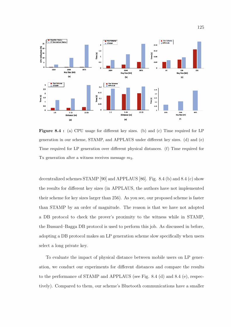
125
Figure 8.4 : (a) CPU usage for different key sizes. (b) and (c) Time required for LP
generation in our scheme, STAMP, and APPLAUS under different key sizes. (d) and (e)
Time required for LP generation over different physical distances. (f) Time required for
Tx generation after a witness receives message m3.
decentralized schemes STAMP [90] and APPLAUS [86]. Fig. 8.4 (b) and 8.4 (c) show
the results for different key sizes (in APPLAUS, the authors have not implemented
their scheme for key sizes larger than 256). As you see, our proposed scheme is faster
than STAMP by an order of magnitude. The reason is that we have not adopted
a DB protocol to check the prover’s proximity to the witness while in STAMP,
the Bussard–Bagga DB protocol is used to perform this job. As discussed in before,
adopting a DB protocol makes an LP generation scheme slow specifically when users
select a long private key.
To evaluate the impact of physical distance between mobile users on LP gener-
ation, we conduct our experiments for different distances and compare the results
to the performance of STAMP and APPLAUS (see Fig. 8.4 (d) and 8.4 (e), respec-
tively). Compared to them, our scheme’s Bluetooth communications have a smaller
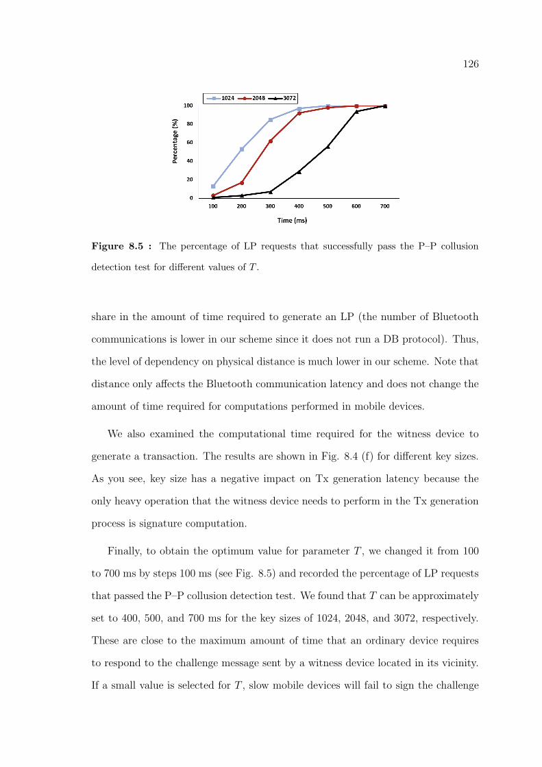
126
Figure 8.5 : The percentage of LP requests that successfully pass the P–P collusion
detection test for different values of T .
share in the amount of time required to generate an LP (the number of Bluetooth
communications is lower in our scheme since it does not run a DB protocol). Thus,
the level of dependency on physical distance is much lower in our scheme. Note that
distance only affects the Bluetooth communication latency and does not change the
amount of time required for computations performed in mobile devices.
We also examined the computational time required for the witness device to
generate a transaction. The results are shown in Fig. 8.4 (f) for different key sizes.
As you see, key size has a negative impact on Tx generation latency because the
only heavy operation that the witness device needs to perform in the Tx generation
process is signature computation.
Finally, to obtain the optimum value for parameter T , we changed it from 100
to 700 ms by steps 100 ms (see Fig. 8.5) and recorded the percentage of LP requests
that passed the P–P collusion detection test. We found that T can be approximately
set to 400, 500, and 700 ms for the key sizes of 1024, 2048, and 3072, respectively.
These are close to the maximum amount of time that an ordinary device requires
to respond to the challenge message sent by a witness device located in its vicinity.
If a small value is selected for T , slow mobile devices will fail to sign the challenge
127
message and send it back to the witness in the given time T . Therefore, a specific
tolerance can be considered for mobile devices with a slower CPU speed. However,
increasing T can provide a malicious prover with the opportunity to successfully
conduct a P–P collusion attack.
8.4 Conclusion
In this chapter, we proposed a blockchain–based, secure, and privacy–aware ar-
chitecture for LP generation and verification. The target of the proposed scheme
is to prevent dishonest mobile users from submitting fake check–ins and location
claims with LBSPs. It relies on the collaboration of mobile devices that generate an
LP for other mobile devices. We also integrated an incentive mechanism into the
proposed scheme to reward mobile users who collaborate with the system. The main
strengths of the proposed architecture are the following: (1) It does not require a
central trusted authority to operate due to employing the blockchain decentralized
architecture. (2) It has reliable performance against P–P and P–W collusions to
which the majority of the current schemes are vulnerable. (3) Our prototype im-
plementation shows that the LP generation procss in the proposed scheme is faster
than the existing schemes due to employing a faster mechanism for proximity check-
ing. (4) It preserves users’ location privacy as they commit to their spatiotemporal
data before it is published and added to the public ledger. Thus, it is not possible
to infer a user’s location data by exploring the public ledger.
In the next chapter, we explore anonymity of users in social networks and pro-
pose Harmonised and Stable DC–net (HSDC–net), a self–organising protocol for
anonymous communications in social networks. We also present the results of our
prototype implementation that shows HSDC–net achieves low latencies and can be
efficiently integrated into social network applications.

128
Part III
Anonymity–Based Approach
129
Chapter 9
Literature Review and Preliminaries
9.1 Introduction
In the last part of this thesis, we investigate anonymity as another approach to
provide privacy in social networks. As far as we know, social networks do not offer
publicly available anonymous group messaging. If these services are employed by
social network service providers, users can be able to create a group in social media
and anonymously post their opinions. For example, consider a group of journalists;
each journalist wishes to publish some secret government information that he/she
obtained from a confidential source. Using an anonymous communication protocol,
they can create a group in social media and anonymously publish their posts without
the risk of prosecution (see [37–39] for more example applications). Note that the
protocol not only needs to hide the origin of each post, but it must also be resistant
against traffic analysis to prevent a government agency or an ISP from identifying
the message publishers by monitoring and analysing the journalists’ traffic in the
network.
To offer anonymity, several anonymous communication networks (ACNs) have
been proposed so far such as onion routing [40], AN.ON [41–42], and Tor [43]. These
solutions work based on mixnet [44], a basic anonymous communication protocol.
However, to guarantee users’ anonymity, they need access to a set of geographically
distributed servers (or mixes) such that at least some of them are trusted [45]. In
addition, mixnet–based networks cannot provide the necessary protection against
traffic analysis attacks [37], [46–48]. These attacks can be conducted by powerful
130
adversaries like large ISPs who can monitor users’ traffic in the network [46]. Din-
ing Cryptographers network (DC–net) [49] is another anonymous communication
protocol that guarantees protection against traffic analysis attacks. Unlike mixnet,
DC–net is completely performed by the users themselves and does not require any
proxy. However, DC–net suffers from three critical issues that reduce its practi-
cality. Firstly, there is a collision possibility issue. Users’ messages are exposed
to corruption due to possible collisions. In DC–net, every user publishes a vector
of data that has N elements (positions or slots) where N is the number of users
in the group who want to anonymously publish a message. It requires every user
to place his/her message in a unique slot where other users must insert their keys
XORed together. Any deviation from this procedure makes all the users’ messages
unrecoverable. Secondly, DC–net is vulnerable to disruptions and Denial of Service
(DoS) attacks since a malicious user can disrupt the protocol by sending irrelevant
bit–streams in each of the N slots.
Finally, DC–net is able to provide anonymity only for a few protocol cycles.
We name this issue the Short stability problem. To the best of our knowledge,
no previous research work has identified this flaw in the DC–net performance. We
prove that it is feasible to infer the origin of each message, after users published
their messages for at least three protocol cycles.
9.2 Literature Review
In this section, we present a brief review of the literature on anonymous commu-
nication protocols. Prior significant research work in this area started in the early
1980s when Chaum presented mixnet [44]. In mixnet, users’ encrypted messages are
batched together and successively relayed into the network after they are decrypted
and shuffled by a set of proxies (named as mixes). Several extensions of the mixnet
protocol have been proposed so far such as onion routing [40], Tor [43], An.On
131
[42], and Mixminion [80]. However, these protocols require that users’ messages are
passed through a series of proxies which results in high latency and makes them
vulnerable to traffic analysis [81]. Moreover, they are vulnerable to active attacks
and disruptions which break the anonymity guarantees and cause protocol jamming,
respectively [46], [52], [82]. In addition, mixnet–based protocols offer anonymity as
long as at least one mix in the network executes the protocol honestly.
Beside the original mixnet, Chaum introduced DC–net as another option to-
wards anonymous communication [49]. DC–net is a distributed and non–interactive
protocol that allows a group of users to anonymously publish their messages in a
single broadcast round. It provides users with secure anonymous communication if
the protocol is executed honestly. However, DC–net suffers from three critical issues
that make it impractical [38–39], [50–52].
To address the DC–net problems, a number of DC–net extensions have been
introduced. Dissent [38] focuses on addressing traffic analysis and DoS attacks to
which mixnet and DC–net protocols are vulnerable. For this reason, the authors of
Dissent have proposed a mechanism to trace disrupting (misbehaving) users. This is
called accountability in the literature. However, in Dissent, the employed shuffling
mechanism imposes a delay at the start of each round that makes the protocol
impractical for delay–sensitive applications [52].
Herbivore [39] is another anonymous group messaging protocol that provides
anonymity by dividing a large group of network users into smaller DC–net subgroups.
In fact, in Herbivore, the size of user groups is reduced in order to limit the attack
surface. This enables the protocol to provide only small sizes of anonymity sets.
Although DC–net–based protocols have a decentralized and non–interactive struc-
ture, a few numbers of server–based protocols have also been proposed in the litera-
ture. For example, Wolinsky et al. [82] suggest a client/server architecture to achieve
132
a high level of scalability. In their proposed protocol many untrusted clients anony-
mously publish their messages through a smaller and more trusted set of servers.
The protocol offers traffic analysis resistance and strong anonymity, provided that
there is at least one honest server. However, the proposed disruptor tracing proce-
dure is too costly. To solve this issue, public–key cryptography and zero–knowledge
proofs are used in Verdict [46] to infer and exclude any misbehaviour before it results
in a disruption. However, no security analysis has been presented in the paper to
proof its security. Riffle [47] is another server–based protocol proposed in this area
of research. It consists of a small set of servers that provide anonymity for a group
of users. However, it still relies on at least one trusted proxy server.
Prior work on privacy issue of Location–Based Services has mostly focused on K–
Anonymity and Dummy–Based methods although some efforts have recently done
on other techniques such as Differential Privacy [9], [64] and Cryptography–Based
[72–73] schemes.
K–Anonymity efforts [74–78] require a trusted third–party server which is called
an anonymizer, between users and LSP. The anonymizer receives service requests
from a user and enlarges its location into a region (cloaking region) so that it con-
tains the locations of K-1 other users as well as location of the requesting user.
Therefore, the adversary cannot identify the requesting user among other K-1 users.
The advantage of these methods is that the communication cost between users and
anonymizer is reduced, however, they suffer from decreased QoS because when there
are not enough users near the requested user, the anonymizer has to increase the
radius of cloaking region, hence, the increased processing times results in a greater
service latency. To solve this problem, some efforts have been done in [76–78] to
increase QoS. In these papers the area of cloaking region is minimized by using
footprints–historical locations of other users.
133
Although the mentioned efforts have solved the low QoS problem, they still rely
on a trusted third–party anonymizer which is a disadvantage for these schemes.
However, in [5] a K–Anonymity privacy protection scheme has been proposed which
doesn’t rely on a trusted anonymizer between users and LSP. But their method still
requires a DataBase Management System (DBMS) to operate.
Several dummy–based location privacy schemes [4], [12], [13–16] have been pro-
posed so far for location privacy protection. In all of them users send their location
data including noise (some fake location data or dummies) to LSP directly. Thus,
there is no need to a trusted anonymizer. In [4] and [12], two dummy generation
algorithms have been presented, Moving in a Neighbourhood and Moving in a Lim-
ited Neighbourhood. In these algorithms, the first dummy set is selected randomly
but next dummies are generated in a neighbourhood of the previous position of the
dummies. Also, a cost reduction technique was proposed in [4] to limit the commu-
nications overhead caused by sending dummies. However, generating dummies at
random or through a fixed rule can not provide flexible location privacy for users.
Hence, in [11], a Privacy–Area Aware scheme is proposed based on a flexible dummy
generation algorithm in which dummies are generated according to either a virtual
grid or circle. This approach provides configurable and controllable dummy genera-
tion by which it is possible to control the user’s location privacy. But a disadvantage
of this method is that it doesn’t consider nature of the region. For example, some
dummies may be generated in places which are unlikely for a user to be there (e.g., in
a river). To solve this problem in [13] a Dummy–Location Selection (DLS) method
has been proposed to prevent the adversary from exploiting side information such
as a region map. This is done by carefully selecting dummies based on the entropy
metric.
But in [14] it has been showed that when a user adopts one of the aforementioned
dummy–based methods, the adversary can identify some dummies with a minimum
134
correct ratio of 58% by means of the spatiotemporal correlation between neighbour-
ing location sets. Therefore, they have proposed a Spatiotemporal Correlation–
Aware privacy protection scheme in which correlated dummies are filtered out and
only uncorrelated dummies are sent to LSP. But this method can protect user’s loca-
tion privacy under some conditions only and if the adversary estimates the threshold
angle which is used to filter space correlated dummies, he will be able to identify
dummies or even the user’s real location.
9.3 Preliminaries
This section presents the foundation for the next sections. After briefly reviewing
DC–net protocol, we introduce its drawbacks and explain why it requires modifica-
tions.
9.3.1 DC–net Overview
DC–net [49] is a distributed and non–interactive protocol proposed to provide
anonymous communications for a group of users who wish to anonymously publish
their messages in the group. Its title comes from the example by which Chaum
explained his proposed protocol:
Three cryptographers sit around a table in a restaurant to have dinner. They
are informed by a waiter that someone has anonymously paid their bill. The payer
can be one of them or the bill might have been paid by the NSA (National Security
Agency). They respect each other’s right to make an anonymous payment, but
they are curious to see if NSA has paid the bill. Thus, they perform the following
protocol:
For all pairs, two cryptographers share a secret bit by tossing an unbiased coin
behind their menu such that only those two cryptographers see the result. Thus,
cryptographer A, for example, has two secret bits kAB and kAC that have been shared
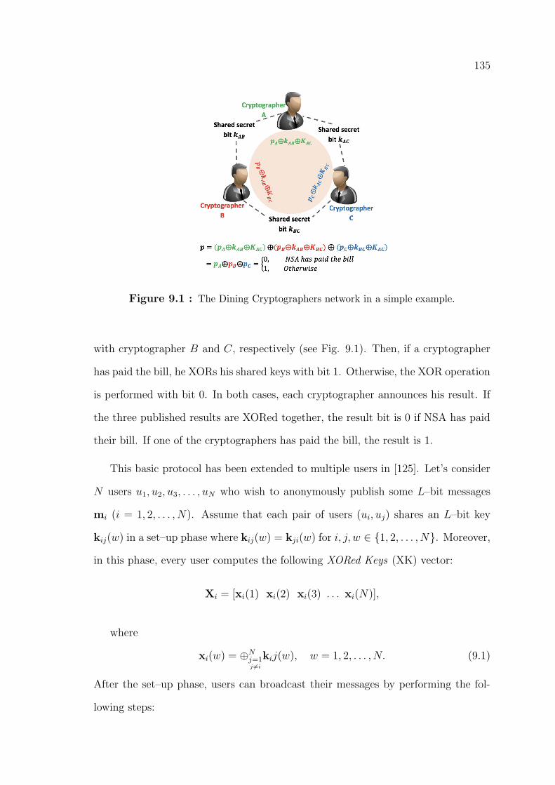
135
Figure 9.1 : The Dining Cryptographers network in a simple example.
with cryptographer B and C, respectively (see Fig. 9.1). Then, if a cryptographer
has paid the bill, he XORs his shared keys with bit 1. Otherwise, the XOR operation
is performed with bit 0. In both cases, each cryptographer announces his result. If
the three published results are XORed together, the result bit is 0 if NSA has paid
their bill. If one of the cryptographers has paid the bill, the result is 1.
This basic protocol has been extended to multiple users in [125]. Let’s consider
N users u1, u2, u3, . . . , uN who wish to anonymously publish some L–bit messages
mi (i = 1, 2, . . . , N). Assume that each pair of users (ui, uj) shares an L–bit key
kij(w) in a set–up phase where kij(w) = kji(w) for i, j, w ∈ {1, 2, . . . , N}. Moreover,
in this phase, every user computes the following XORed Keys (XK) vector:
Xi = [xi(1) xi(2) xi(3) . . . xi(N)],
where
xi(w) = ⊕Nj=1j 6=i
kij(w), w = 1, 2, . . . , N. (9.1)
After the set–up phase, users can broadcast their messages by performing the fol-
lowing steps:
136
(1) Every user ui randomly selects a slot (position) si ∈ {1, 2, . . . , N} in his/her
Xi vector.
(2) The XK vector Xi is converted to Yi by replacing xi(si) with mi ⊕ xi(si).
Then, Yi is published.
Since ⊕Ni=1xi(w) = 0 for w = 1, 2, . . . , N , if users have selected different positions,
we have:
⊕Ni=1Yi = M′,
where M′
is the users’ messages vector M = [m1 m2 m3 . . .mN ] in which the
elements have been shuffled. We define M′
as the Shuffled Messages Vector (SMV)
since we need to refer to this vector frequently.
Therefore, the users’ messages are published for the group in such a way that
the origin of each message is anonymous.
9.3.2 DC–net Drawbacks
Although DC–net offers strong anonymity, it suffers from some critical issues:
• Collision possibility : In DC–net, it is assumed that the users select different
slots (or positions) in the XK vector Xi. However, if two users ui and uj place
their messages in the same slot (i.e., si = sj are selected by them), mi ⊕mj
is recovered in the M′
vector at the final stage that makes both mi and mj
unrecoverable (note that in this case, one element of M′
is obtained as 0).
• Vulnerability against disruptions (security issue): DC–net works well only
when users execute the protocol honestly. The protocol is jammed if a mali-
cious user, for example, fills Yi with some random bits and publishes it. In
this case none of the users’ messages is successfully recovered.
Apart from that, we identified another critical issue, i.e. short stability, in the
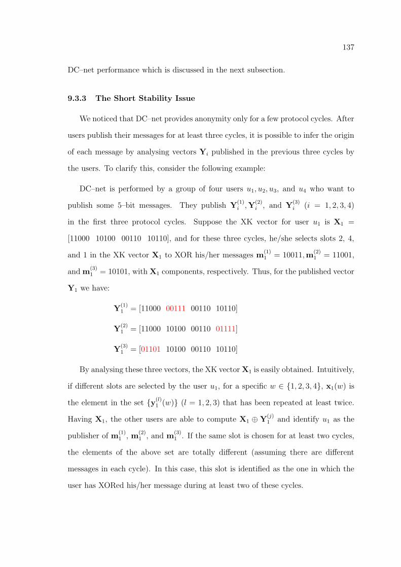
137
DC–net performance which is discussed in the next subsection.
9.3.3 The Short Stability Issue
We noticed that DC–net provides anonymity only for a few protocol cycles. After
users publish their messages for at least three cycles, it is possible to infer the origin
of each message by analysing vectors Yi published in the previous three cycles by
the users. To clarify this, consider the following example:
DC–net is performed by a group of four users u1, u2, u3, and u4 who want to
publish some 5–bit messages. They publish Y(1)i ,Y
(2)i , and Y
(3)i (i = 1, 2, 3, 4)
in the first three protocol cycles. Suppose the XK vector for user u1 is X1 =
[11000 10100 00110 10110], and for these three cycles, he/she selects slots 2, 4,
and 1 in the XK vector X1 to XOR his/her messages m(1)1 = 10011,m
(2)1 = 11001,
and m(3)1 = 10101, with X1 components, respectively. Thus, for the published vector
Y1 we have:
Y(1)1 = [11000 00111 00110 10110]
Y(2)1 = [11000 10100 00110 01111]
Y(3)1 = [01101 10100 00110 10110]
By analysing these three vectors, the XK vector X1 is easily obtained. Intuitively,
if different slots are selected by the user u1, for a specific w ∈ {1, 2, 3, 4}, x1(w) is
the element in the set {y(l)1 (w)} (l = 1, 2, 3) that has been repeated at least twice.
Having X1, the other users are able to compute X1 ⊕ Y(j)1 and identify u1 as the
publisher of m(1)1 , m
(2)1 , and m
(3)1 . If the same slot is chosen for at least two cycles,
the elements of the above set are totally different (assuming there are different
messages in each cycle). In this case, this slot is identified as the one in which the
user has XORed his/her message during at least two of these cycles.
138
9.4 Conclusion
In this chapter, we reviewed the existing literature on anonymity and reviewed
the advantages and disadvantages of different anonymous communication protocols.
It is concluded that .
Moreover, this chapter presented some preliminaries as the foundation for the
next chapter. In this regard, the concept of differential privacy and the Laplace
mechanisms were presented. Moreover, we discussed the necessity of customising the
adjacency relation defined in the standard differential privacy to match its definition
with the location domain.
In the next chapter, we introduce our anonymity–based solution, i.e. Harmonized
and Stable DC–net (HSDC–net) for privacy preservation in social networks. HSDC–
net is a self–organizing protocol for anonymous communications that enables users
of social networks to anonymously publish their messages.
139
Chapter 10
Anonymity in Social Networks
10.1 Introduction
While hiding the contents of users’ messages has been successfully addressed be-
fore, the anonymization of message senders remains a challenge, specifically if users
do not trust their ISP. To resolve this challenge, several solutions have been pro-
posed so far. Among these solutions, the Dining Cryptographers network protocol
(DC–net) provides the strongest anonymity guarantees. However, DC–net suffers
from two critical issues that makes it impractical: (1) collision possibility, (2) vul-
nerability against disruptions and DoS attacks. Moreover, we noticed a third critical
issue during our investigation: (3) DC–net users can be deanonymized after they
publish at least three messages. In other words, anonymity is provided only for a
few cycles of message publishing. In this paper, we propose Harmonized and Stable
DC-net (HSDC–net), a self–organizing protocol for anonymous communications. In
our protocol design, we first resolve the short stability issue and obtain SDC–net, a
stable extension of DC–net. Then, we integrate the Slot Reservation and Disruption
Management sub–protocols into SDC–net to overcome the collision and security is-
sues, respectively. Our prototype implementation shows that HSDC–net achieves
low latencies that makes it a practical protocol.
In the next section, we present our anonymity–based solution, i.e. Harmonized
and Stable DC–net (HSDC–net) for privacy preservation in social networks.
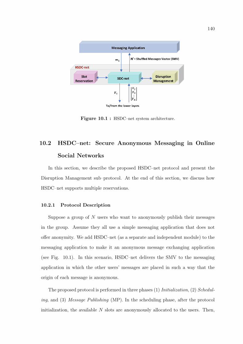
140
Figure 10.1 : HSDC–net system architecture.
10.2 HSDC–net: Secure Anonymous Messaging in Online
Social Networks
In this section, we describe the proposed HSDC–net protocol and present the
Disruption Management sub–protocol. At the end of this section, we discuss how
HSDC–net supports multiple reservations.
10.2.1 Protocol Description
Suppose a group of N users who want to anonymously publish their messages
in the group. Assume they all use a simple messaging application that does not
offer anonymity. We add HSDC–net (as a separate and independent module) to the
messaging application to make it an anonymous message exchanging application
(see Fig. 10.1). In this scenario, HSDC–net delivers the SMV to the messaging
application in which the other users’ messages are placed in such a way that the
origin of each message is anonymous.
The proposed protocol is performed in three phases (1) Initialization, (2) Schedul-
ing, and (3) Message Publishing (MP). In the scheduling phase, after the protocol
initialization, the available N slots are anonymously allocated to the users. Then,
141
they publish their messages by continuously executing the MP phase. In the follow-
ing, we present each phase individually and in the order that they are performed.
Initialization
In this phase, all the N users in the group execute an initialization algorithm
individually. Considering user u1, this algorithm takes as input the user vector
U = [u2 u3 . . . uN ] and generates the following items in collaboration with the
users specified in U :
• A matrix of pairwise symmetric keys K(0)1 =
K(0)12
K(0)13
. . .
K(0)1N
,
in which K(0)1j = [k
(0)1j (1) k
(0)1j (2) . . . k
(0)1j (N)], where k
(0)1j (w), (w = 1, 2, . . . , N)
is an L–bit secret symmetric key that u1 shares with uj (j = 2, 3, . . . , N) to
use in slot w.
• Vector R1 = [r12 r13 . . . r1N ], where r1j is a random integer number shared
secretly between users u1 and uj.
Moreover, by executing this algorithm, each user ui signs the following two items
using his/her private key and sends them to user uj (j = 1, 2, . . . , N, j 6= i) (we
assume every user has adopted a public/private key pair and already published
his/her public key in the network):
• The jth row of matrix K(0)i (i.e., K
(0)1j for user u1).
• The jth element in Ri (i.e., rij).
We will use these signatures for disruption management.
142
Scheduling Phase
In this phase, every user ui performs the SR sub–protocol that is executed in the
following steps:
(1) ui creates vector Si = [Si(1) Si(2) . . .Si(N)], in which every element consists of
L zero bits (i.e., Si(w) = 0 for w = 1, 2, . . . , N).
(2) Two random integer numbers l and n are selected by ui in [1, L] and [1, N ],
respectively. Then, the lth bit in Si(n) is set to 1 to obtain S′
i (assuming S′
i is a
single bit–stream, it has only a single bit 1 in the position l + (n− 1)L).
(3) ui computes and publishes the following vector Zi:
Zi = [Zi(1) Zi(2) . . .Zi(N)],
where Zi(w) = [⊕Nj=1j 6=i
k(0)ij (w)]⊕ S
′
i(w) ,w = 1, 2, . . . , N .
(4) Upon receiving N−1 vector Zj (j = 1, 2, . . . , N, j 6= i) from the other users (who
performed the same procedure), ui computes vector V = [V(1) V(2) . . .V(N)], in
which V(w) = ⊕Ni=1Zi(w). Note that V(w) = ⊕Ni=1S′
i(w) because the terms related
to the pairwise keys are cancelled out when they are XORed together. Thus, if we
consider vector V as a single bit stream, it shows all the 1 bits set by the users
(in step 2) placed in their primary positions (see Fig. 10.2). (5) ui computes the
hamming weight of V, i.e., H = Hamming(V) that indicates how many bits 1 exist
in V. Based on the obtained H, two situations are supposable:
• If H = N , there is no collision and every user has selected a unique slot. In
this case, (considering V as a single bit stream) ui highlights his/her selected
1 (set in step 2) in V, keeps all the 1s and removes all the 0s of V (Fig. 10.2).
This results in a bit stream of size N in which all the N bits are 1. In this bit
stream, the bit number associated with the position in which the highlighted
bit 1 has been placed is the slot assigned to ui.
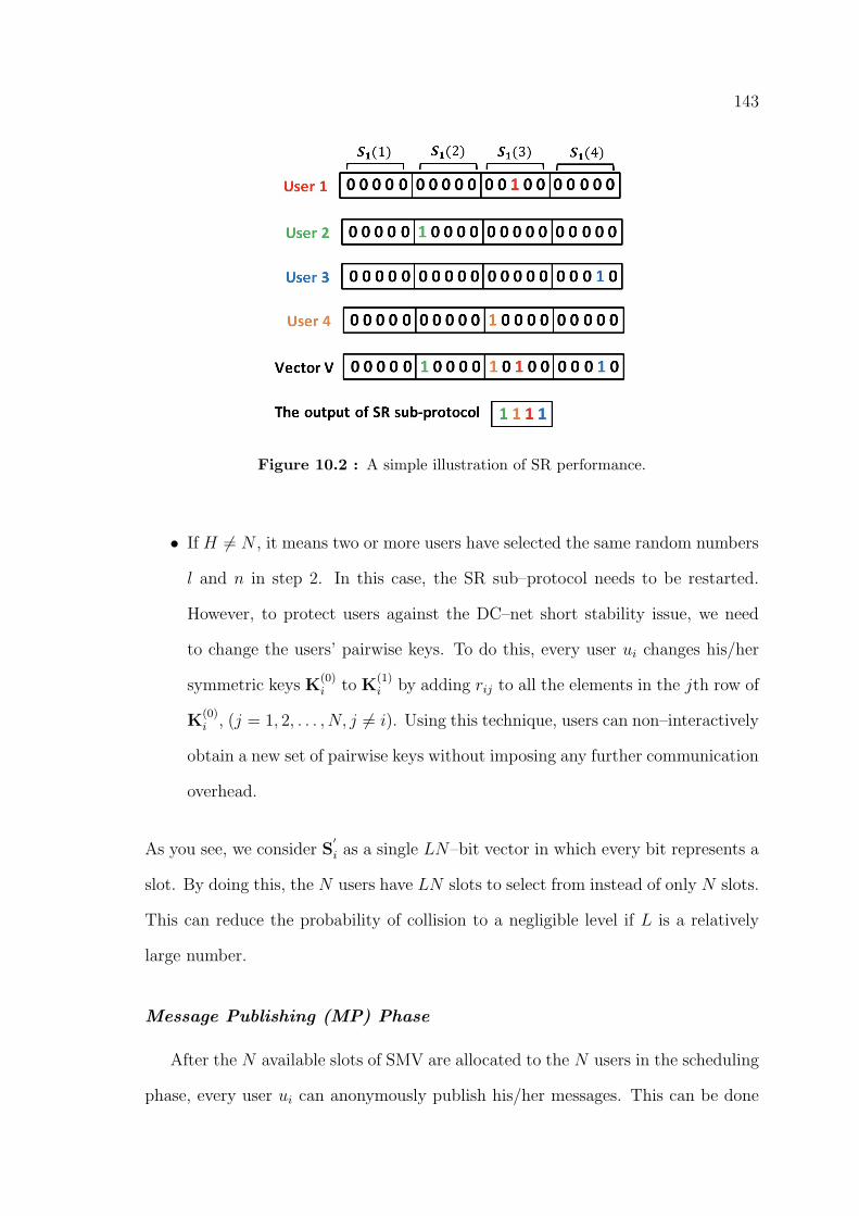
143
Figure 10.2 : A simple illustration of SR performance.
• If H 6= N , it means two or more users have selected the same random numbers
l and n in step 2. In this case, the SR sub–protocol needs to be restarted.
However, to protect users against the DC–net short stability issue, we need
to change the users’ pairwise keys. To do this, every user ui changes his/her
symmetric keys K(0)i to K
(1)i by adding rij to all the elements in the jth row of
K(0)i , (j = 1, 2, . . . , N, j 6= i). Using this technique, users can non–interactively
obtain a new set of pairwise keys without imposing any further communication
overhead.
As you see, we consider S′
i as a single LN–bit vector in which every bit represents a
slot. By doing this, the N users have LN slots to select from instead of only N slots.
This can reduce the probability of collision to a negligible level if L is a relatively
large number.
Message Publishing (MP) Phase
After the N available slots of SMV are allocated to the N users in the scheduling
phase, every user ui can anonymously publish his/her messages. This can be done
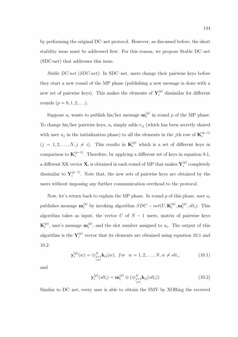
144
by performing the original DC–net protocol. However, as discussed before, the short
stability issue must be addressed first. For this reason, we propose Stable DC–net
(SDC-net) that addresses this issue.
Stable DC-net (SDC-net): In SDC–net, users change their pairwise keys before
they start a new round of the MP phase (publishing a new message is done with a
new set of pairwise keys). This makes the elements of Y(p)i dissimilar for different
rounds (p = 0, 1, 2, . . .).
Suppose ui wants to publish his/her message m(p)i in round p of the MP phase.
To change his/her pairwise keys, ui simply adds rij (which has been secretly shared
with user uj in the initialization phase) to all the elements in the jth row of K(p−1)i
(j = 1, 2, . . . , N, j 6= i). This results in K(p)i which is a set of different keys in
comparison to K(p−1)i . Therefore, by applying a different set of keys in equation 9.1,
a different XK vector Xi is obtained in each round of MP that makes Y(p)i completely
dissimilar to Y(p−1)i . Note that, the new sets of pairwise keys are obtained by the
users without imposing any further communication overhead to the protocol.
Now, let’s return back to explain the MP phase. In round p of this phase, user ui
publishes message m(p)i by invoking algorithm SDC − net(U,K(p)
i ,m(p)i , slti). This
algorithm takes as input, the vector U of N − 1 users, matrix of pairwise keys
K(p)i , user’s message m
(p)i , and the slot number assigned to ui. The output of this
algorithm is the Y(p)i vector that its elements are obtained using equation 10.1 and
10.2:
y(p)i (w) = ⊕Nj=1
j 6=ikij(w), for w = 1, 2, . . . , N, w 6= slti, (10.1)
and
y(p)i (slti) = m
(p)i ⊕ (⊕Nj=1
j 6=ikij(slti)) (10.2)
Similar to DC–net, every user is able to obtain the SMV by XORing the received
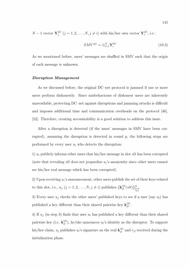
145
N − 1 vector Y(p)j (j = 1, 2, . . . , N, j 6= i) with his/her own vector Y
(p)i , i.e.:
SMV (p) = ⊕Ni=1Y(p)i (10.3)
As we mentioned before, users’ messages are shuffled in SMV such that the origin
of each message is unknown.
Disruption Management
As we discussed before, the original DC–net protocol is jammed if one or more
users perform dishonestly. Since misbehaviours of dishonest users are inherently
unavoidable, protecting DC–net against disruptions and jamming attacks is difficult
and imposes additional time and communication overheads on the protocol [46],
[52]. Therefore, creating accountability is a good solution to address this issue.
After a disruption is detected (if the users’ messages in SMV have been cor-
rupted), assuming the disruption is detected in round p, the following steps are
performed by every user ui who detects the disruption:
1) ui publicly informs other users that his/her message in slot slt has been corrupted
(note that revealing slt does not jeopardize ui’s anonymity since other users cannot
see his/her real message which has been corrupted).
2) Upon receiving ui’s announcement, other users publish the set of their keys related
to this slot, i.e., uj (j = 1, 2, . . . , N, j 6= i) publishes {k(p)jl (slt)}Nl=1
l6=j.
3) Every user uj checks the other users’ published keys to see if a user (say ul) has
published a key different than their shared pairwise key k(p)jl .
4) If uj (in step 3) finds that user ul has published a key different than their shared
pairwise key (i.e. k(p)jl ), he/she announces ul’s identity as the disruptor. To support
his/her claim, uj publishes ul’s signature on the real k(p)jl and rjl received during the
initialization phase.
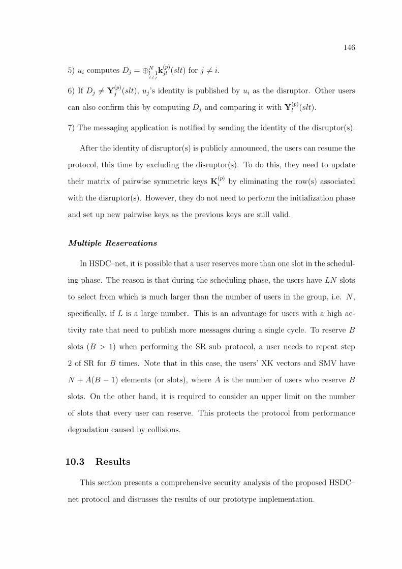
146
5) ui computes Dj = ⊕Nl=1l 6=j
k(p)jl (slt) for j 6= i.
6) If Dj 6= Y(p)j (slt), uj’s identity is published by ui as the disruptor. Other users
can also confirm this by computing Dj and comparing it with Y(p)l (slt).
7) The messaging application is notified by sending the identity of the disruptor(s).
After the identity of disruptor(s) is publicly announced, the users can resume the
protocol, this time by excluding the disruptor(s). To do this, they need to update
their matrix of pairwise symmetric keys K(p)i by eliminating the row(s) associated
with the disruptor(s). However, they do not need to perform the initialization phase
and set up new pairwise keys as the previous keys are still valid.
Multiple Reservations
In HSDC–net, it is possible that a user reserves more than one slot in the schedul-
ing phase. The reason is that during the scheduling phase, the users have LN slots
to select from which is much larger than the number of users in the group, i.e. N ,
specifically, if L is a large number. This is an advantage for users with a high ac-
tivity rate that need to publish more messages during a single cycle. To reserve B
slots (B > 1) when performing the SR sub–protocol, a user needs to repeat step
2 of SR for B times. Note that in this case, the users’ XK vectors and SMV have
N + A(B − 1) elements (or slots), where A is the number of users who reserve B
slots. On the other hand, it is required to consider an upper limit on the number
of slots that every user can reserve. This protects the protocol from performance
degradation caused by collisions.
10.3 Results
This section presents a comprehensive security analysis of the proposed HSDC–
net protocol and discusses the results of our prototype implementation.
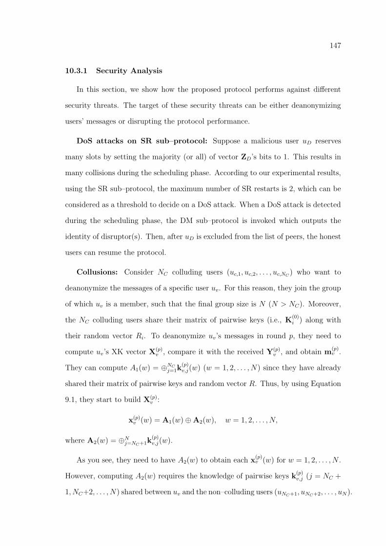
147
10.3.1 Security Analysis
In this section, we show how the proposed protocol performs against different
security threats. The target of these security threats can be either deanonymizing
users’ messages or disrupting the protocol performance.
DoS attacks on SR sub–protocol: Suppose a malicious user uD reserves
many slots by setting the majority (or all) of vector ZD’s bits to 1. This results in
many collisions during the scheduling phase. According to our experimental results,
using the SR sub–protocol, the maximum number of SR restarts is 2, which can be
considered as a threshold to decide on a DoS attack. When a DoS attack is detected
during the scheduling phase, the DM sub–protocol is invoked which outputs the
identity of disruptor(s). Then, after uD is excluded from the list of peers, the honest
users can resume the protocol.
Collusions: Consider NC colluding users (uc,1, uc,2, . . . , uc,NC ) who want to
deanonymize the messages of a specific user uv. For this reason, they join the group
of which uv is a member, such that the final group size is N (N > NC). Moreover,
the NC colluding users share their matrix of pairwise keys (i.e., K(0)i ) along with
their random vector Ri. To deanonymize uv’s messages in round p, they need to
compute uv’s XK vector X(p)v , compare it with the received Y(p)
v , and obtain m(p)v .
They can compute A1(w) = ⊕NCj=1k(p)v,j(w) (w = 1, 2, . . . , N) since they have already
shared their matrix of pairwise keys and random vector R. Thus, by using Equation
9.1, they start to build X(p)v :
x(p)v (w) = A1(w)⊕A2(w), w = 1, 2, . . . , N,
where A2(w) = ⊕Nj=NC+1k(p)v,j(w).
As you see, they need to have A2(w) to obtain each x(p)v (w) for w = 1, 2, . . . , N .
However, computing A2(w) requires the knowledge of pairwise keys k(p)v,j (j = NC +
1, NC+2, . . . , N) shared between uv and the non–colluding users (uNC+1, uNC+2, . . . , uN).
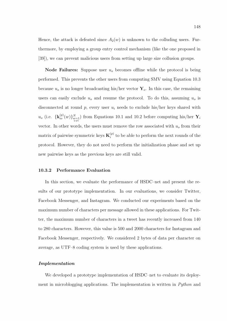
148
Hence, the attack is defeated since A2(w) is unknown to the colluding users. Fur-
thermore, by employing a group entry control mechanism (like the one proposed in
[39]), we can prevent malicious users from setting up large size collusion groups.
Node Failures: Suppose user uo becomes offline while the protocol is being
performed. This prevents the other users from computing SMV using Equation 10.3
because uo is no longer broadcasting his/her vector Yo. In this case, the remaining
users can easily exclude uo and resume the protocol. To do this, assuming uo is
disconnected at round p, every user ui needs to exclude his/her keys shared with
uo (i.e. {k(p)io (w)}Nw=1
w 6=i) from Equations 10.1 and 10.2 before computing his/her Yi
vector. In other words, the users must remove the row associated with uo from their
matrix of pairwise symmetric keys K(p)i to be able to perform the next rounds of the
protocol. However, they do not need to perform the initialization phase and set up
new pairwise keys as the previous keys are still valid.
10.3.2 Performance Evaluation
In this section, we evaluate the performance of HSDC–net and present the re-
sults of our prototype implementation. In our evaluations, we consider Twitter,
Facebook Messenger, and Instagram. We conducted our experiments based on the
maximum number of characters per message allowed in these applications. For Twit-
ter, the maximum number of characters in a tweet has recently increased from 140
to 280 characters. However, this value is 500 and 2000 characters for Instagram and
Facebook Messenger, respectively. We considered 2 bytes of data per character on
average, as UTF–8 coding system is used by these applications.
Implementation
We developed a prototype implementation of HSDC–net to evaluate its deploy-
ment in microblogging applications. The implementation is written in Python and
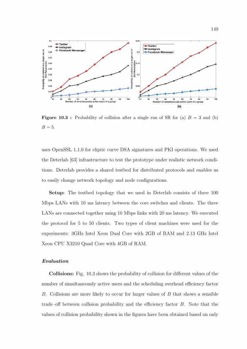
149
Figure 10.3 : Probability of collision after a single run of SR for (a) B = 3 and (b)
B = 5.
uses OpenSSL 1.1.0 for eliptic curve DSA signatures and PKI operations. We used
the Deterlab [63] infrastructure to test the prototype under realistic network condi-
tions. Deterlab provides a shared testbed for distributed protocols and enables us
to easily change network topology and node configurations.
Setup: The testbed topology that we used in Deterlab consists of three 100
Mbps LANs with 10 ms latency between the core switches and clients. The three
LANs are connected together using 10 Mbps links with 20 ms latency. We executed
the protocol for 5 to 50 clients. Two types of client machines were used for the
experiments: 3GHz Intel Xeon Dual Core with 2GB of RAM and 2.13 GHz Intel
Xeon CPU X3210 Quad Core with 4GB of RAM.
Evaluation
Collisions: Fig. 10.3 shows the probability of collision for different values of the
number of simultaneously active users and the scheduling overhead efficiency factor
B. Collisions are more likely to occur for larger values of B that shows a sensible
trade–off between collision probability and the efficiency factor B. Note that the
values of collision probability shown in the figures have been obtained based on only
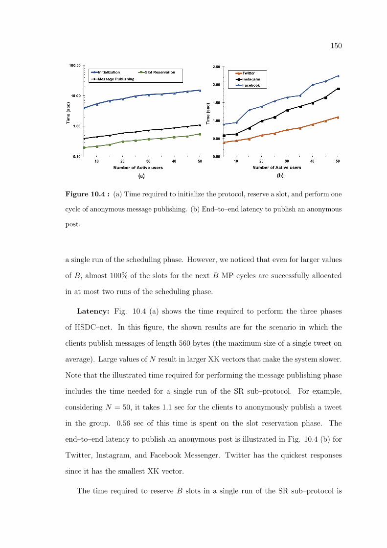
150
Figure 10.4 : (a) Time required to initialize the protocol, reserve a slot, and perform one
cycle of anonymous message publishing. (b) End–to–end latency to publish an anonymous
post.
a single run of the scheduling phase. However, we noticed that even for larger values
of B, almost 100% of the slots for the next B MP cycles are successfully allocated
in at most two runs of the scheduling phase.
Latency: Fig. 10.4 (a) shows the time required to perform the three phases
of HSDC–net. In this figure, the shown results are for the scenario in which the
clients publish messages of length 560 bytes (the maximum size of a single tweet on
average). Large values of N result in larger XK vectors that make the system slower.
Note that the illustrated time required for performing the message publishing phase
includes the time needed for a single run of the SR sub–protocol. For example,
considering N = 50, it takes 1.1 sec for the clients to anonymously publish a tweet
in the group. 0.56 sec of this time is spent on the slot reservation phase. The
end–to–end latency to publish an anonymous post is illustrated in Fig. 10.4 (b) for
Twitter, Instagram, and Facebook Messenger. Twitter has the quickest responses
since it has the smallest XK vector.
The time required to reserve B slots in a single run of the SR sub–protocol is
151
Figure 10.5 : Time required to reserve B slots in a single run of SR for different values
of B
shown in Fig. 10.5. As the figure indicates, for B = 1 and B = 3 only a single run of
SR is required to reserve B slots. However, some collisions have occurred for B = 5
and B = 7 in larger values of N that caused the SR sub–protocol to be restarted.
Finally, in Fig. 10.6, the end–to–end latency of HSDC–net and some of the most
well–known anonymity protocols are compared. As you see, HSDC–net outperforms
Dissent [38] and Verdict [46] protocols in terms of speed. The reason is that the
SR and MP phases in HSDC–net are performed using simple and lightweight oper-
ations i.e. XOR and SUM. However, in Dissent and Verdict, heavy–duty tasks are
performed for public–key encryption/decryptions and zero–knowledge proofs. Note
that the latency of HSDC–net will be shorter if we have B > 1 because in this case
only a single run of SR is required for B consecutive cycles of message publishing.
Communication overhead: We also examined the maximum possible size of
the XK vector for Twitter, Facebook Messenger, and Instagram. Considering 50
users who publish their messages simultaneously in a group, the maximum size of
an XK vector is obtained 27, 49, and 195 KB, for these applications, respectively.
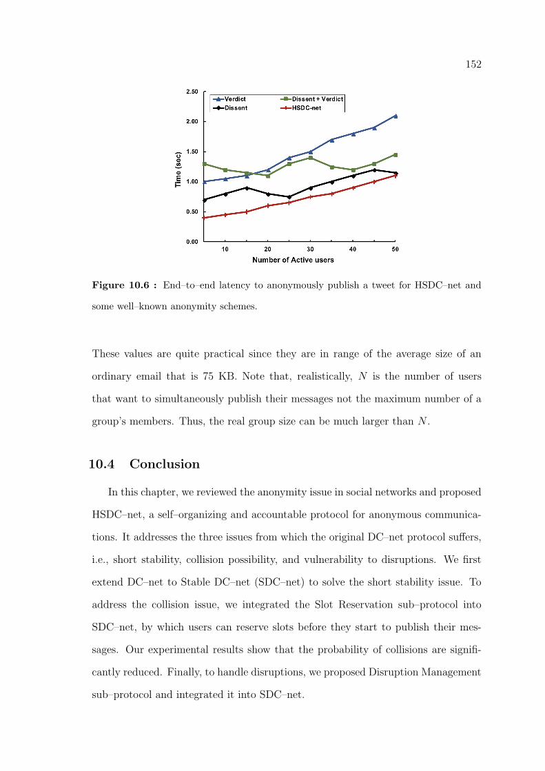
152
Figure 10.6 : End–to–end latency to anonymously publish a tweet for HSDC–net and
some well–known anonymity schemes.
These values are quite practical since they are in range of the average size of an
ordinary email that is 75 KB. Note that, realistically, N is the number of users
that want to simultaneously publish their messages not the maximum number of a
group’s members. Thus, the real group size can be much larger than N .
10.4 Conclusion
In this chapter, we reviewed the anonymity issue in social networks and proposed
HSDC–net, a self–organizing and accountable protocol for anonymous communica-
tions. It addresses the three issues from which the original DC–net protocol suffers,
i.e., short stability, collision possibility, and vulnerability to disruptions. We first
extend DC–net to Stable DC–net (SDC–net) to solve the short stability issue. To
address the collision issue, we integrated the Slot Reservation sub–protocol into
SDC–net, by which users can reserve slots before they start to publish their mes-
sages. Our experimental results show that the probability of collisions are signifi-
cantly reduced. Finally, to handle disruptions, we proposed Disruption Management
sub–protocol and integrated it into SDC–net.

153
In the next chapter, we introduce our second anonymity–based solution for pri-
vacy preservation in location–based services and social networks.
154
Chapter 11
A Hybrid Location Privacy Protection Scheme in
Big Data Environment
11.1 Introduction
In this chapters we explore location privacy in location–based services (LBS)
and proposes a hybrid location privacy protection scheme for users. Indeed, loca-
tion privacy is a significant challenge of LBS. Particularly, by the advantage of big
data handling tools that are easily available, huge location data can be managed
and processed easily by an adversary to obtain user private information from LBS.
So far, many methods have been proposed to preserve location privacy of users in
these services. Among them, dummy–based methods have various advantages in
terms of implementation and low computation costs. However, they suffer from the
spatiotemporal correlation issue when users submit consecutive requests. In this
chapter, we investigate this issue and propose a practical dummy–based location
privacy protection scheme to address it. The proposed method filters out the cor-
related fake location data (dummies) before submissions. Therefore, the adversary
can not identify the user’s real location. Evaluations and experiments show that
our proposed filtering technique significantly improves the performance of existing
dummy–based methods and enables them to effectively protect the user’s location
privacy in the big data environment.
155
11.2 Background
With the recent huge advance in technology, we are now facing the age of big
data. According to the IBM report∗ we create 2.5 quintillion bytes of data every
day, and 90% of the data in the world today has been created in the last two years
alone. This data comes from sensors, social media sites, emails, digital pictures
and videos, and different mobile applications. Among these applications, Location-
Based Services (LBS) have a significant and growing impact on big data since they
produce a large number of location data every day [104–105]. These location data
have three dimensions, personal, spatial and temporal, indicating a user’s location at
a specific time. Location–Based Service Provider (LSP) uses these data to provide
information, such as the nearest ATM, restaurant, or a retail store.
However, a significant challenge for LBS is how to protect users location privacy.
Since LSPs store location data of users, it is feasible that an adversary at LSP
obtains private information about a user by analysing her position data. Even if a
user’s name or ID is hidden or pseudonyms are used, it has been shown that privacy
may be invaded by analysing position data only [4], [106]. Hence, it is necessary to
develop a location privacy preserving system to prevent LSPs from obtaining the
user’s real location.
Many methods have been proposed to achieve this goal [4], [12], [75–76], [79].
These methods can be categorized in different ways. In [79], they have been catego-
rized as Spatial Anonymization, Obfuscation, and Private Retrieve methods. How-
ever, in [14] they have been classified from a different point of view as Dummy–based,
K–Anonymity, Differential Privacy and Cryptography–based methods. Regardless
how we classify them, they all have a common goal: to protect user’s location privacy
while at the same time user benefits from advantages of the service.
∗https://www.ibm.com/software/data/bigdata/what-is-big-data.html
156
Each of the aforementioned methods has its own strengths and weaknesses. But
among them, dummy–based methods have drawn the attention of researchers due
to their unique features ([4], [12], [10–11], [14–16]). In dummy-based methods, in
addition to the user’s real location, some fake location data (dummies) are sent to
LSP by the user as a service enquiry. This prevents the adversary from distinguishing
the user’s real location. LSP then provides the requested information to the user,
who can easily extract her own required information among them and ignores the
others. The most important advantage of dummy–based methods is that they do not
rely on a trusted third party anonymizer. Moreover, users do not need to encrypt
the requests. Thus, there is no need to share a key between the LSP and users.
However, for some LBS in which users send requests continuously, such as route
navigation applications, it has been shown that dummy–based methods suffer from
a crucial restriction, which has been named as the spatiotemporal correlation issue
[14]. When a user sends consecutive service queries, there is always two types of
correlation between neighbouring location sets, i.e., space and time correlations. In
Fig. 11.1, we show an example of these correlations. As we can see in the diagram,
there are two consecutive location data, each one consisted of the user’s real location
and four dummies. Although dummy D′3 in the second location set is geographically
close to other dummies and the user’s real location, it isn’t reachable in the request
time interval since there is a river between them. Hence, the adversary can exploit
this time correlation and identify it as a fake location data. Moreover, you can
see that D′4 is not in the same direction with other dummies and the real location.
Thus, the adversary can identify it as a dummy because it is separated from the
trajectory, especially when we consider more consecutive requests.
Experiments in [14] indicated that the existing dummy–based schemes can pro-
tect user location privacy with no more than 42% success ratio when users send
consecutive requests. To solve the mentioned problem, a spatiotemporal correlation–
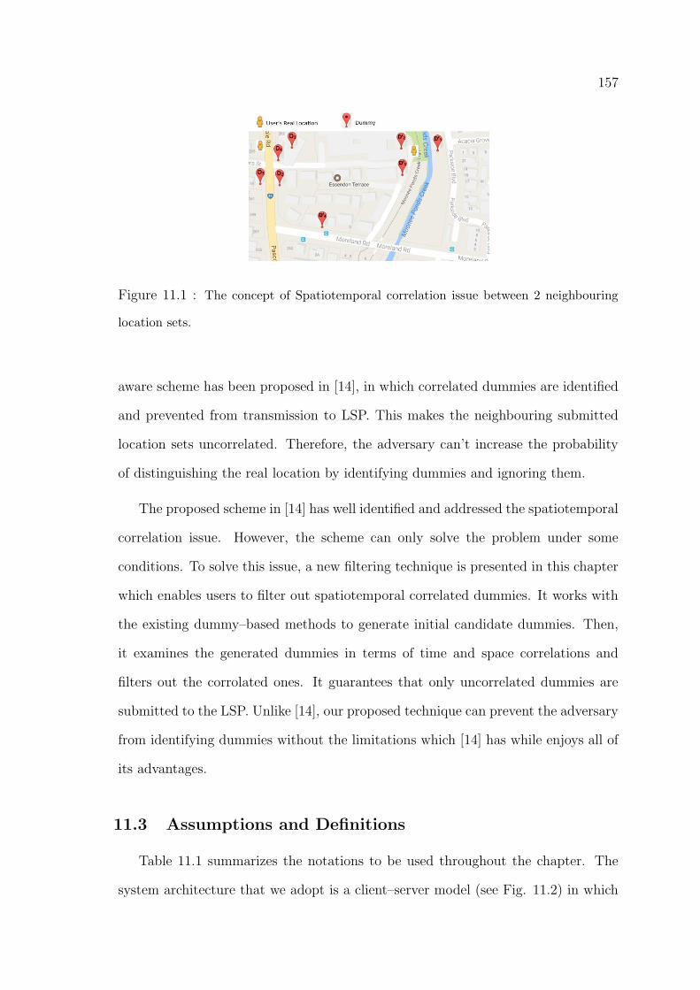
157
Figure 11.1 : The concept of Spatiotemporal correlation issue between 2 neighbouring
location sets.
aware scheme has been proposed in [14], in which correlated dummies are identified
and prevented from transmission to LSP. This makes the neighbouring submitted
location sets uncorrelated. Therefore, the adversary can’t increase the probability
of distinguishing the real location by identifying dummies and ignoring them.
The proposed scheme in [14] has well identified and addressed the spatiotemporal
correlation issue. However, the scheme can only solve the problem under some
conditions. To solve this issue, a new filtering technique is presented in this chapter
which enables users to filter out spatiotemporal correlated dummies. It works with
the existing dummy–based methods to generate initial candidate dummies. Then,
it examines the generated dummies in terms of time and space correlations and
filters out the corrolated ones. It guarantees that only uncorrelated dummies are
submitted to the LSP. Unlike [14], our proposed technique can prevent the adversary
from identifying dummies without the limitations which [14] has while enjoys all of
its advantages.
11.3 Assumptions and Definitions
Table 11.1 summarizes the notations to be used throughout the chapter. The
system architecture that we adopt is a client–server model (see Fig. 11.2) in which

158
Table 11.1 : Summary of Notation
Symbol Meaning
Ki User location privacy requirement number
lji jth dummy generated at ith service request
lri User’s real location at ith request
Ti Time at which ith location is sent to LSP
Li={l1i , l2i ,. . . , lKi−1i , lri } Location set at ith service request
< lri−1, lri > The real movement path
no trusted third–party is required. LSP is assumed to be untrusted and knows what
location privacy protection algorithm the user runs. Also, we assume that LSP has
enough public side information about the requesting region (e.g., he has a detailed
map of the region), therefore, he can utilize the spatiotemporal correlation between
neighbouring location sets to identify the user’s real location.
At ith service request, the algorithm generates Ki-1 dummies, (l1i , l2i ,. . . , lKi−1
i ),
and the location set Li is formed by adding the user’s real location lri to dummies.
Then, as we can see in Fig. 11.2, Li is submitted by the user to LSP at time Ti
. LSP processes the request and sends the requested information back to the user
including Ki service query results. Finally, the user picks up her own query result
and ignores the others.
11.3.1 User’s Location Privacy Requirement
If we define Ki as the parameter which reflects the user’s location privacy re-
quirements, then the adversary must not be able to identify the user’s real location
with a probability greater than 1/Ki. We define this as the minimum User’s Loca-
tion Privacy Requirement (ULPR). Therefore, in order to satisfy it, the user must
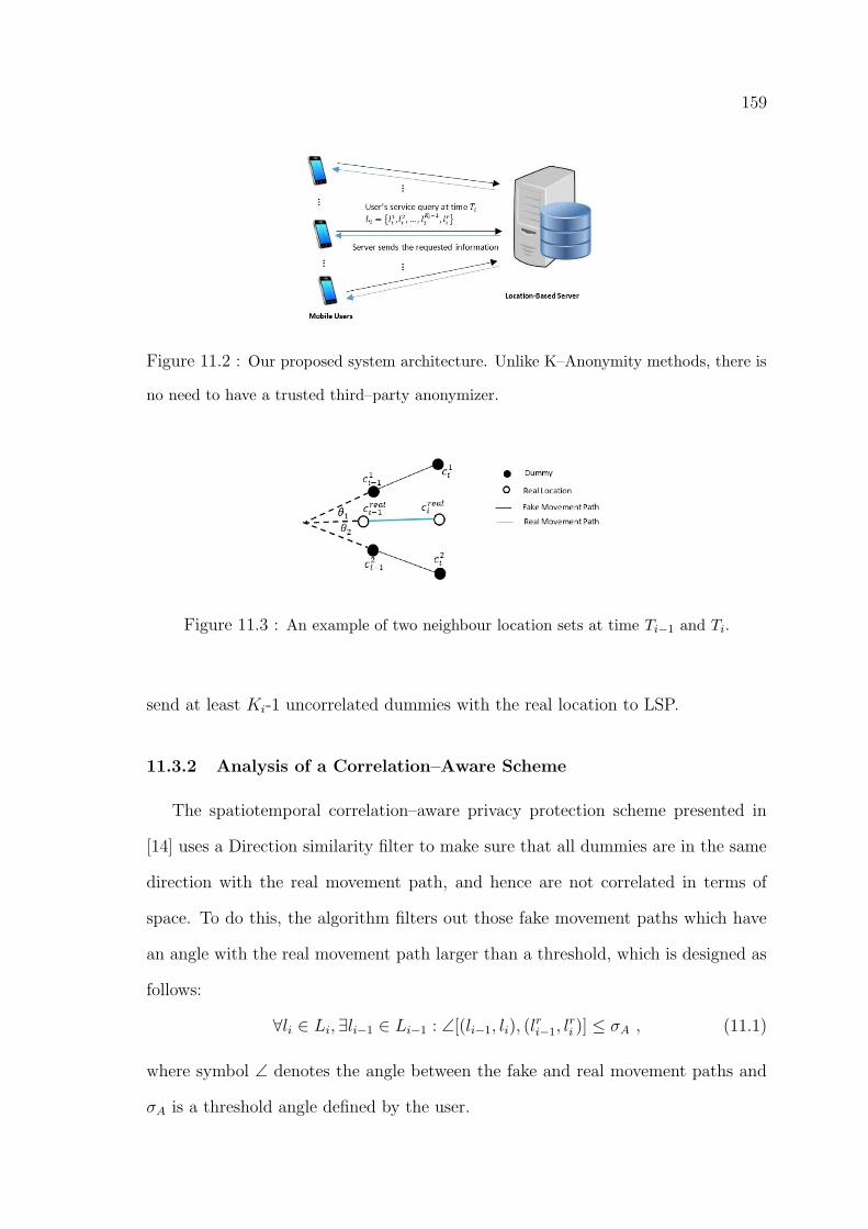
159
Figure 11.2 : Our proposed system architecture. Unlike K–Anonymity methods, there is
no need to have a trusted third–party anonymizer.
Figure 11.3 : An example of two neighbour location sets at time Ti−1 and Ti.
send at least Ki-1 uncorrelated dummies with the real location to LSP.
11.3.2 Analysis of a Correlation–Aware Scheme
The spatiotemporal correlation–aware privacy protection scheme presented in
[14] uses a Direction similarity filter to make sure that all dummies are in the same
direction with the real movement path, and hence are not correlated in terms of
space. To do this, the algorithm filters out those fake movement paths which have
an angle with the real movement path larger than a threshold, which is designed as
follows:
∀li ∈ Li, ∃li−1 ∈ Li−1 : ∠[(li−1, li), (lri−1, l
ri )] ≤ σA , (11.1)
where symbol ∠ denotes the angle between the fake and real movement paths and
σA is a threshold angle defined by the user.
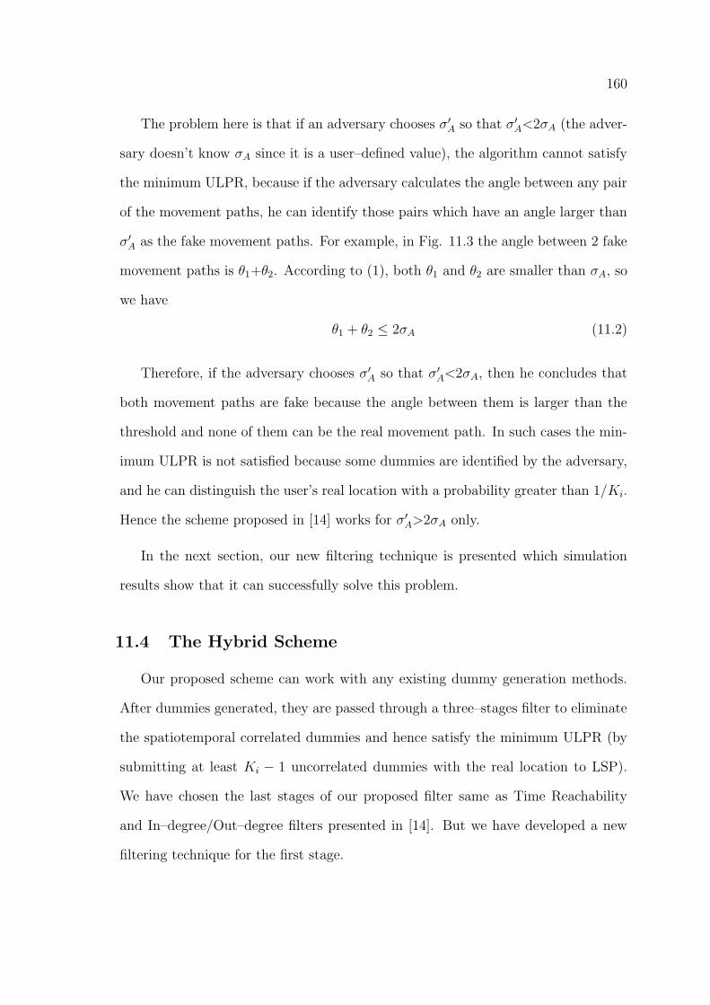
160
The problem here is that if an adversary chooses σ′A so that σ′A<2σA (the adver-
sary doesn’t know σA since it is a user–defined value), the algorithm cannot satisfy
the minimum ULPR, because if the adversary calculates the angle between any pair
of the movement paths, he can identify those pairs which have an angle larger than
σ′A as the fake movement paths. For example, in Fig. 11.3 the angle between 2 fake
movement paths is θ1+θ2. According to (1), both θ1 and θ2 are smaller than σA, so
we have
θ1 + θ2 ≤ 2σA (11.2)
Therefore, if the adversary chooses σ′A so that σ′A<2σA, then he concludes that
both movement paths are fake because the angle between them is larger than the
threshold and none of them can be the real movement path. In such cases the min-
imum ULPR is not satisfied because some dummies are identified by the adversary,
and he can distinguish the user’s real location with a probability greater than 1/Ki.
Hence the scheme proposed in [14] works for σ′A>2σA only.
In the next section, our new filtering technique is presented which simulation
results show that it can successfully solve this problem.
11.4 The Hybrid Scheme
Our proposed scheme can work with any existing dummy generation methods.
After dummies generated, they are passed through a three–stages filter to eliminate
the spatiotemporal correlated dummies and hence satisfy the minimum ULPR (by
submitting at least Ki − 1 uncorrelated dummies with the real location to LSP).
We have chosen the last stages of our proposed filter same as Time Reachability
and In–degree/Out–degree filters presented in [14]. But we have developed a new
filtering technique for the first stage.
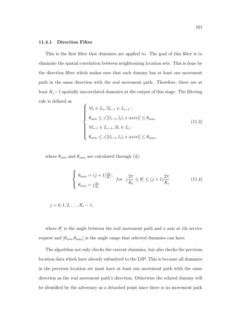
161
11.4.1 Direction Filter
This is the first filter that dummies are applied to. The goal of this filter is to
eliminate the spatial correlation between neighbouring location sets. This is done by
the direction filter which makes sure that each dummy has at least one movement
path in the same direction with the real movement path. Therefore, there are at
least Ki−1 spatially uncorrelated dummies at the output of this stage. The filtering
rule is defined as
∀li ∈ Li, ∃li−1 ∈ Li−1 :
θmin ≤ ∠[(li−1, li), x axis)] ≤ θmax
∀li−1 ∈ Li−1, ∃li ∈ Li :
θmin ≤ ∠[(li−1, li), x axis)] ≤ θmax,
(11.3)
where θmin and θmax are calculated through (4):
θmax = (j + 1) 2πKi
;
θmin = j 2πKi
for j2π
Ki
≤ θri ≤ (j + 1)2π
Ki
(11.4)
j = 0, 1, 2, . . . , Ki − 1,
where θri is the angle between the real movement path and x axis at ith service
request and [θmin,θmax] is the angle range that selected dummies can have.
The algorithm not only checks the current dummies, but also checks the previous
location data which have already submitted to the LSP. This is because all dummies
in the previous location set must have at least one movement path with the same
direction as the real movement path’s direction. Otherwise the related dummy will
be identified by the adversary as a detached point since there is no movement path
162
leaves it in the same direction with other movement paths. Unlike [14], there is no
need to use a user–defined parameter like σA which adds some side information to
the adversary’s knowledge.
11.4.2 Time Reachability Filter
After that space correlation between neighbouring dummies has been removed
in the first stage, time reachability filter checks the reachable time of every possible
movement path formed between the existing dummies and the previous location set.
Every movement path which is unreachable in the request time interval Ti − Ti−1 is
eliminated by this filter. Therefore, the adversary is no longer able to identify fake
movement paths from their unusual reachable time. In fact, this filter guarantees
that every dummy has at least one movement path which is reachable in the request
time interval. Thus, all dummies which pass this filter and the user’s real location
have same entropy in terms of time reachability.
After this stage, there must be at least Ki − 1 dummies to satisfy the minimum
(ULPR), otherwise (in case that more than M −Ki + 1 dummies are filtered where
M is the total number of initial dummies) the dummy generation algorithm will be
re–invoked to generate another initial dummy set and the algorithm will be restarted.
11.4.3 Detached/Hub Filter
This filter has the same structure as In–degree/Out–degree filter in [14] has. The
dummies finally are applied to this filter to make sure that:
• There is at least one movement path for each dummy (there is no detached
dummy which has no possible movement path starts from or ends at it).
• There is at least one dummy with larger number of movement paths than what
the real location has. (If the real location has the most number of movement
paths, it is identified by the adversary since it is a movement hub [14])
163
Again, at the end of this stage, we must have at least Ki − 1 dummies to satisfy
the minimum ULPR. In fact, the last stage completes the performance of other two
stages and if in any of the previous stages a dummy has been detached (due to
eliminating its movement paths) or if the real location has become the movement
hub, the detached/hub filter will sort it out and eliminate this additional information
which can be exploited by the adversary to identify the user’s real location.
11.5 Analysis on the proposed scheme
The adversary is assumed to be able to store and analyse the user’s location data
in order to obtain some private information about the user. We assume a location
privacy protection scheme to be secure if it can satisfy the minimum ULPR.
If our scheme is adopted by a user to protect her location privacy, she submits
her query to LSP includes her real location and at least Ki − 1 dummies. Since all
dummies have already passed through direction, time reachability and detached/hub
filters, there is no spatiotemporal correlation between the dummies, also, the move-
ment paths formed by our proposed scheme are indistinguishable. In the other word,
it can be said that:
1) For each dummy, there is at least one movement path which is reachable in
the request time interval. So, totally, there are at least Ki − 1 different movement
paths reachable in the request time interval. Hence, if the adversary wants to exploit
any time correlation between neighbouring location data and choose one movement
path as the real one, he will be successful with a probability of no more than 1/Ki.
2) Through direction filter, only those dummies are selected to submit that
at least one of their corresponding movement paths is in the same direction with
the real movement path. Therefore, if the adversary tries to identify dummies by
means of the space correlation between dummies, he has to choose one among Ki
164
uncorrelated location points which means the success ratio is not more than 1/Ki .
So, our proposed scheme satisfies the minimum ULPR, hence, protects the user’s
location privacy effectively.
11.6 Performance Evaluation
11.6.1 Evaluation Setup
The algorithm has been implemented in Matlab on a Windows 7 laptop with
2.3 GHz Intel i5 CPU and 4GB memory. We use California Points of Interest† as a
real dataset with 208,000 locations including restaurants, bars, shopping centers and
hospitals. Also, we adopt the GridDummy algorithm [11] to generate dummies for
consecutive requests over a real road map of Los Angeles city (source: TIGER/Line
Files‡).
In our experiments, the user’s location privacy requirement K is selected from the
common range 3 to 20 and for simplicity we assume the user has same Ki in all the
requests. Also, for each user we define a trajectory consisted of 11 real locations and
10 movement paths. The reachable time between consecutive locations are obtained
from Google Map API.
We define the number of indistinguishable movement paths as the criteria to
measure the level of location privacy protection. This is because the larger number of
indistinguishable movement paths we have, the less likely the adversary can identify
the user’s real location among dummies.
†https://www.cs.utah.edu/ lifeifei/SpatialDataset.htm
‡https://www.census.gov/geo/maps-data/data/tiger-line.html
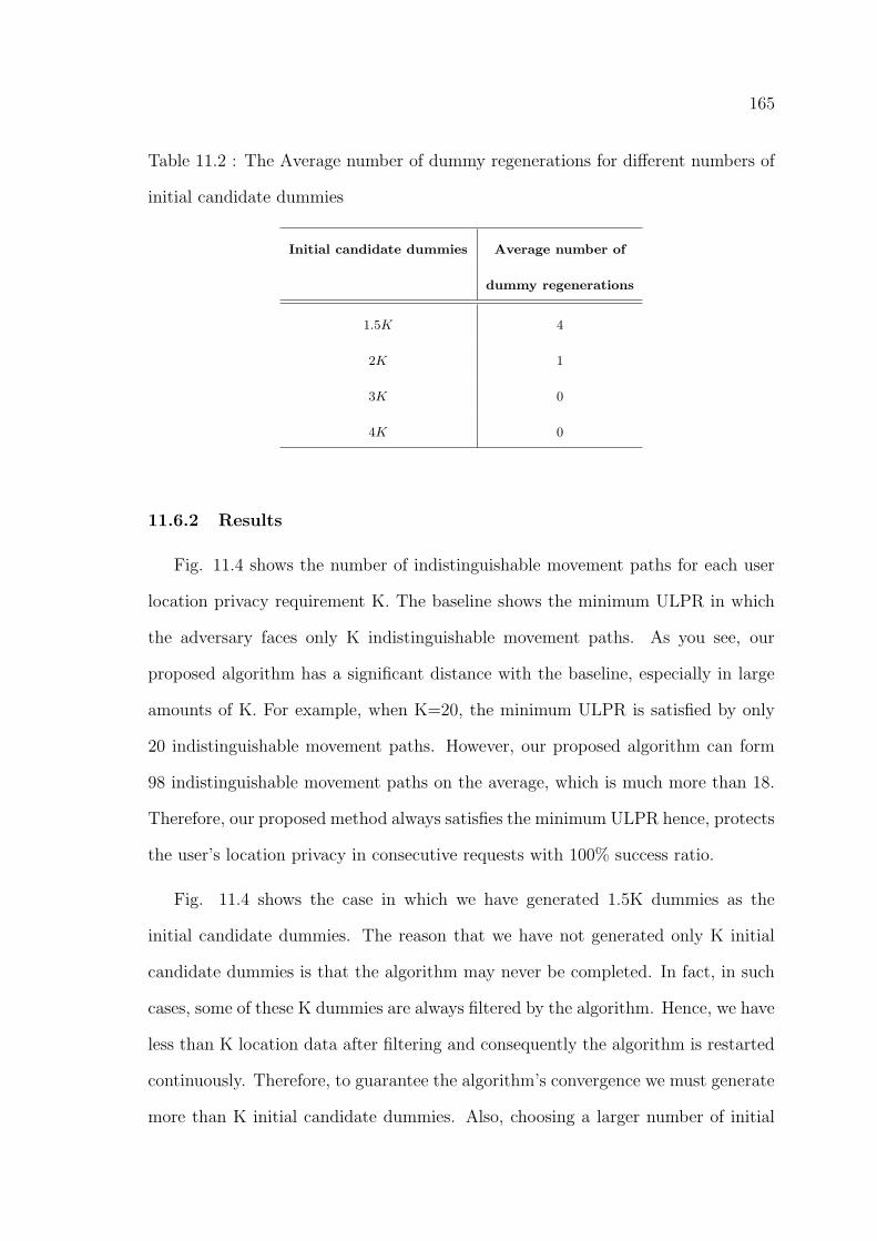
165
Table 11.2 : The Average number of dummy regenerations for different numbers of
initial candidate dummies
Initial candidate dummies Average number of
dummy regenerations
1.5K 4
2K 1
3K 0
4K 0
11.6.2 Results
Fig. 11.4 shows the number of indistinguishable movement paths for each user
location privacy requirement K. The baseline shows the minimum ULPR in which
the adversary faces only K indistinguishable movement paths. As you see, our
proposed algorithm has a significant distance with the baseline, especially in large
amounts of K. For example, when K=20, the minimum ULPR is satisfied by only
20 indistinguishable movement paths. However, our proposed algorithm can form
98 indistinguishable movement paths on the average, which is much more than 18.
Therefore, our proposed method always satisfies the minimum ULPR hence, protects
the user’s location privacy in consecutive requests with 100% success ratio.
Fig. 11.4 shows the case in which we have generated 1.5K dummies as the
initial candidate dummies. The reason that we have not generated only K initial
candidate dummies is that the algorithm may never be completed. In fact, in such
cases, some of these K dummies are always filtered by the algorithm. Hence, we have
less than K location data after filtering and consequently the algorithm is restarted
continuously. Therefore, to guarantee the algorithm’s convergence we must generate
more than K initial candidate dummies. Also, choosing a larger number of initial
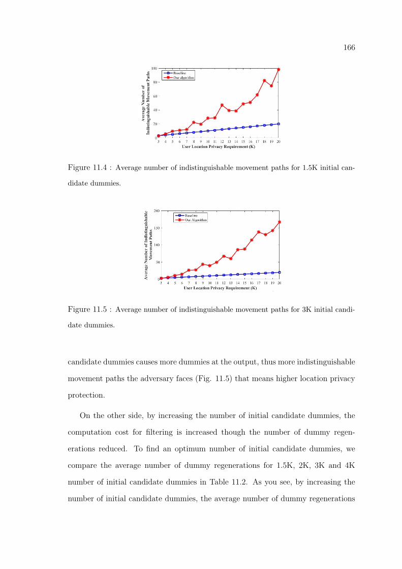
166
Figure 11.4 : Average number of indistinguishable movement paths for 1.5K initial can-
didate dummies.
Figure 11.5 : Average number of indistinguishable movement paths for 3K initial candi-
date dummies.
candidate dummies causes more dummies at the output, thus more indistinguishable
movement paths the adversary faces (Fig. 11.5) that means higher location privacy
protection.
On the other side, by increasing the number of initial candidate dummies, the
computation cost for filtering is increased though the number of dummy regen-
erations reduced. To find an optimum number of initial candidate dummies, we
compare the average number of dummy regenerations for 1.5K, 2K, 3K and 4K
number of initial candidate dummies in Table 11.2. As you see, by increasing the
number of initial candidate dummies, the average number of dummy regenerations
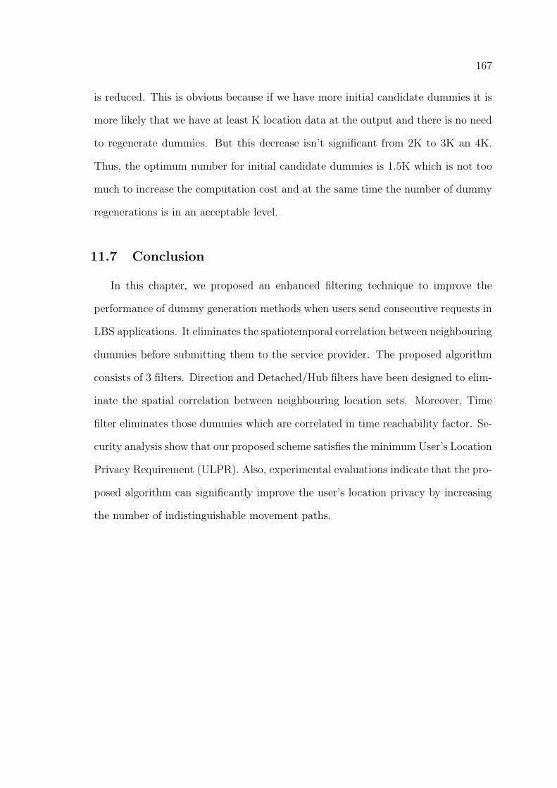
167
is reduced. This is obvious because if we have more initial candidate dummies it is
more likely that we have at least K location data at the output and there is no need
to regenerate dummies. But this decrease isn’t significant from 2K to 3K an 4K.
Thus, the optimum number for initial candidate dummies is 1.5K which is not too
much to increase the computation cost and at the same time the number of dummy
regenerations is in an acceptable level.
11.7 Conclusion
In this chapter, we proposed an enhanced filtering technique to improve the
performance of dummy generation methods when users send consecutive requests in
LBS applications. It eliminates the spatiotemporal correlation between neighbouring
dummies before submitting them to the service provider. The proposed algorithm
consists of 3 filters. Direction and Detached/Hub filters have been designed to elim-
inate the spatial correlation between neighbouring location sets. Moreover, Time
filter eliminates those dummies which are correlated in time reachability factor. Se-
curity analysis show that our proposed scheme satisfies the minimum User’s Location
Privacy Requirement (ULPR). Also, experimental evaluations indicate that the pro-
posed algorithm can significantly improve the user’s location privacy by increasing
the number of indistinguishable movement paths.
168
Chapter 12
Summary
12.1 Introduction
The recent advances in smartphone technology and positioning systems has en-
abled social network service providers to offer a variety of location–based applica-
tions and services for their users. In these applications, real–time location data of
mobile users is utilised to provide requested information or access to a resource or
service. However, preserving location privacy of users is a big challenge for the ser-
vice providers since users share their location data either with other users or with a
service provider.
In this regard, many research efforts have been made to address this issue. From
our literature review, we found that differential privacy, as a promising framework,
can be employed to develop reliable and efficient privacy preserving mechanisms in
social networks. However, Anonymity and Cryptography–Based approaches have
also been used in this domain. Each of the mentioned approaches has its own
benefits and disadvantages as discussed in this thesis. In this chapter, we present a
summary of the research work done in this study.
12.2 Conclusion
In this research study, we investigate the location privacy issue in social network
and develop Distance–based Location Privacy Protection mechanism (DBLP2), a
customisable location privacy protection approach that is uniquely designed for so-
cial network users. In DBLP2, the concept of social distance is utilised to generalise
169
users’ location data before it is published in a social network. The level of gen-
eralisation is decided based on the social distance between users. Furthermore, to
preserve users’ location privacy in location–based applications and services (the pop-
ular and fast growing social network applications), we propose three privacy–aware
location verification schemes: (i) Privacy–Aware and Secure Proof Of pRoximiTy
(PASPORT), (ii) Secure, Privacy–Aware and collusion Resistant poSition vErifi-
cation(SPARSE), and (iii) a blockchain–based location verification scheme. They
prevent dishonest users from conducting location spoofing attacks while protect lo-
cation privacy of users. To the best of our knowledge, majority of the existing
location verification schemes do not preserve location privacy of users.
Theoretical and experimental results show that DBLP2 mechanism provides the
optimum data utility regarding the trade–off between privacy protection and data
utility. In addition, our experimental results indicate that DBLP2 is offers variable
location privacy protection and is resilience to post processing. Regarding the pro-
posed SPARSE scheme, our analysis and experiments show that SPARSE provides
privacy protection as well as security properties for users including integrity, unforge-
ability and non–transferability of the location proofs. Moreover, it achieves a highly
reliable performance against collusions. To validate performance of the PASPORT
scheme, we implement a prototype of the proposed scheme on the Android platform.
Extensive experiments indicate that the proposed method can efficiently protect
location–based applications against fake submissions. For the proposed blockchain–
based scheme, our prototype implementation on the Android platform shows that
the proposed scheme outperforms other currently deployed location proof schemes.
We also study the anonymity topic in social networks and utilise it as another
solution to preserve users’ privacy in social networks. In this regard, we
first study the relevant protocols and discuss their features and drawbacks. Then,
170
we introduce Harmonized and Stable DC–net (HSDC–net), a self–organising proto-
col for anonymous communications in social networks. As far as we know, social net-
works do not offer any secure anonymous communication service. In social networks,
privacy of users is preserved using pseudonymity, i.e., users select a pseudonym for
their communications instead of their real identity. However, it has been shown
that pseudonymity does not always result in anonymity (perfect privacy) if users’
activities in social media are linkable. This makes users’ privacy vulnerable to
deanonymisation attacks. Thus, by employing a secure anonymous communication
service, social network service providers will be able to effectively preserve users’
privacy.
The proposed HSDC–net protocol addresses the three issues from which the
original DC–net protocol suffers, i.e., short stability, collision possibility, and vul-
nerability to disruptions. We first extend DC–net to Stable DC–net (SDC–net) to
solve the short stability issue. To address the collision issue, we integrated the Slot
Reservation sub–protocol into SDC–net, by which users can reserve slots before they
start to publish their messages. Our experimental results show that the probability
of collisions are significantly reduced and they are totally avoided after at most two
runs of SR. Finally, to handle disruptions, we proposed Disruption Management
sub–protocol and integrated it into SDC–net. The results of our implementation
show that HSDC–net achieves low latencies that makes it a practical protocol.
171
Bibliography
[1] https://newsroom.fb.com/company-info/
[2] K. Zhang, X. Liang, R. Lu, X. Shen, ”PIF: A Personalized Fine–Grained Spam
Filtering Scheme With Privacy Preservation in Mobile Social Networks”, IEEE
Transactions on Computational Social Systems, vol. 2, no. 3, pp. 41–52, Sep
2015.
[3] https://www.gsa.europa.eu/segment/location-based-services-lbs
[4] H. Kido, Y. Yanagisawa, T. Satoh, ”An anonymous communication technique
using dummies for location-based services,” in IEEE ICPS, 2005.
[5] M. Gruteser, D. Grunwald, ”Anonymous usage of location–based services
through spatial and temporal cloaking,” in ACM Mobisys, 2003.
[6] E. Novak, Q. Li, ”Near-pri: Private, proximity based location sharing”, IEEE
INFOCOM, pp. 37–45, 2014.
[7] R. Schlegel, C. Y. Chow, Q. Huang, D. S. Wong, ”Privacy-Preserving Location
Sharing Services for Social Networks”, IEEE Transactions on Services Com-
puting, vol. 10, no. 5, pp. 811–825, Oct 2017.
[8] C. Dwork, ”Differential privacy,” 33rd International Conference on Automata,
Languages and Programming, Jul 2006.
[9] C. Dwork and A. Roth, ”The algorithmic foundations of differential privacy,”
Foundations and Trends in Theoretical Computer Science, vol. 9, no. 3–4, pp.
211—407, 2014.
172
[10] MR. Nosouhi, V. H. Pham, S. Yu, Y. Xiang, and M. Warren, A Hybrid Location
Privacy Protection Scheme in Big Data Environment”, IEEE GLOBECOM,
2017.
[11] H. Lu, C. S. Jensen, M. L. Yiu, ”PAD: Privacy–area aware, dummy–based
location privacy in mobile services,” in ACM MobiDE, 2008.
[12] H. Kido, Y. Yanagisawa, T. Satoh, ”Protection of location privacy using dum-
mies for location–based services,” in IEEE ICDE Workshops, 2005.
[13] B. Niu, Q. Li, X. Zhu, G. Cao, H. Li, ”Achieving k–anonymity in privacy–aware
location–based services,” in IEEE INFOCOM, 2014.
[14] H. Liu, X. Li, H. Li, J. Ma and X. Ma, ”Spatiotemporal Correlation-Aware
Dummy-Based Privacy Protection Scheme for Location-Based Services,” in
IEEE INFOCOM, 2017.
[15] B. Niu, Z. Zhang, X. Li, H. Li, ”Privacy–area aware dummy generation algo-
rithms for location–based services,” in IEEE ICC, 2014.
[16] B. Niu, Q. Li, X. Zhu, G. Cao, H. Li, ”Enhancing privacy through caching in
location–based services,” in IEEE INFOCOM, 2015.
[17] P. Asuquo, H. Cruickshank, J. Morley, C.P. Ogah, A. Lei, W. Hathal, S. Bao,
and Z. Sun, ”Security and Privacy in Location–Based Services for Vehicular
and Mobile Communications: An Overview, Challenges and Countermeasures”,
IEEE Internet of Things Journal, Early Access, 2018.
[18] Q. D. Vo and P. De, ”A Survey of Fingerprint–Based Outdoor Localization”,
IEEE Communications Surveys & Tutorials, Vol. 18, pp. 491–506, 2016.
[19] R. Gupta and U. P. Rao, ”An Exploration to Location–Based Service and its
Privacy Preserving Techniques: A Survey”, Wireles Personal Communications,
173
vol. 96, issue 2, pp.1973–2007, 2017.
[20] J. Li, G. Liu, C. Yan, and C. Jiang, ”LORI: A Learning–to–Rank–Based In-
tegration Method of Location Recommendation”, IEEE Transactions on Com-
putational Social Systems, vol. 6, no.3, pp. 430–440, Jun. 2019.
[21] “Global Location–based Services Market (2018–2023)”,
https://www.businesswire.com/news/home/20180927005490/en/Global–Location-
based-Services-Market-2018-2023-Projected-Grow
[22] Y. Zheng, M. Li,W. Lou, and Y. T. Hou, “Location Based Handshake and
Private Proximity Test with Location Tags”, IEEE Transactions on Dependable
and Secure Computing, Vol. 14, Issue 4, pp. 406–419, Jul–Aug 2017.
[23] Y. Li, L. Zhou, H. Zhu, and L. Sun, “Privacy–Preserving Location Proof for
Securing Large–Scale Database–Driven Cognitive Radio Networks”, IEEE In-
ternet of Things Journal, Vol. 3, Issue 4, pp. 563–571, Aug 2016.
[24] A. Pham, K. Huguenin, I. Bilogrevic, I. Dacosta, and J.P. Hubaux, “SecureRun:
Cheat–Proof and Private Summaries for Location–Based Activities”, IEEE
Transactions on Mobile Computing, Vol. 15, Issue 8, pp. 2109–2123, Aug 2016.
[25] Z. Gao, H. Zhu, Y. Liu, M. Li, and Z. Cao, “Location Privacy in
Database–driven Cognitive Radio Networks: Attacks and Countermeasures”,
In Proceedings of IEEE INFOCOM, pp. 2751–2759, 2013.
[26] Z. Zhang, L. Zhou, X. Zhao, G. Wang, Y. Su, M. Metzger, H. Zheng, and B.
Y. Zhao, “On the Validity of Geosocial Mobility Traces”, In Proceedings of the
ACM Workshop on Hot Topics in Networks (HotNets), 2013.
[27] D. Bucher, D. Rudi, and R. Buffat, “Captcha Your Location Proof—A Novel
Method for Passive Location Proofs in Adversarial Environments”, In Proceed-
174
ings of 14th International Conference on Location Based Services, pp. 269–291,
2018.
[28] A. Mukherjee, B. Liu, and N. Glance, “Spotting Fake Reviewer Groups in
Consumer Reviews”, In Proceedings of the 21st international conference on
World Wide Web (WWW), pp. 191–200, 2012.
[29] “Nike+ badges and trophies,” http://www.garcard.com/nikeplus.php
[30] “Higi”, https://higi.com
[31] “Oscar Health Using Misfit Wearables To Reward Fit Customers”,
http://www.forbes.com/sites/stevenbertoni/2014/12/08/oscarhealthusing-
misfit-wearables-to-reward-fit-customers
[32] M. Grissa, A. A. Yavuz, and B. Hamdaoui, “Location Privacy Preservation in
Database–Driven Wireless Cognitive Networks Through Encrypted Probabilis-
tic Data Structures”, IEEE Transactions on Cognitive Communications and
Networking, Vol. 3, Issue 2, pp. 255–266, Jun 2017.
[33] K. Zeng, S. K. Ramesh, and Y. Yang, “Location Spoofing Attack and its Coun-
termeasures in Database–Driven Cognitive Radio Networks”, In Proceedings of
IEEE Commun. Netw. Secur. (CNS), pp. 202–210, 2014.
[34] A. van Cleeff, W. Pieters, and R. Wieringa, “Benefits of Location–Based Access
Control: A Literature Study”, IEEE/ACM Int’l Conference on Green Comput-
ing and Communications, Dec 2010.
[35] Y. Baseri, A. Hafid, and S. Cherkaoui, “K–anonymous location–based
fine–grained access control for mobile cloud”, IEEE Annual Consumer Com-
munications & Networking Conference (CCNC), Jan 2016.
175
[36] E. Androulaki, C. Soriente, L. Malisa, and S. Capkun, “Enforcing Location and
Time–Based Access Control on Cloud–Stored Data”, In Proceedings of IEEE
34th International Conference on Distributed Computing Systems (ICDCS), pp.
637–648, Jun 2014.
[37] S. Angel, and S. Setty, “Unobservable Communication Over Fully Untrusted
Infrastructure”, In Proceedings of the 12th USENIX Symposium on Operating
Systems Design and Implementation, pp. 551–569, 2016.
[38] H. Corrigan-Gibbs, B. Ford, “Dissent: Accountable Anonymous Group Mes-
saging”, In Proceedings of the 17th ACM conference on Computer and commu-
nications security (ACM CCS’ 10), pp. 340–350, 2010.
[39] S. Goel, M. Robson, M. Polte, and E. G. Sirer, “Herbivore: A Scalable and
Efficient Protocol for Anonymous Communication”, Technical Report. Cornell
University, USA, 2003.
[40] D. Goldschlag, M. Reed, and P. Syverson, “Onion Routing for Anonymous and
Private Internet Connections” Communications of the ACM, vol. 42, issue 2 ,
pp.39–41, 1999.
[41] O. Berthold, H. Federrath, and S. K opsell, “Web Mixes: A System for Anony-
mous and Unobservable Internet Access”, In Designing Privacy Enhancing
Technologies, Springer, Berlin, pp. 115–129, 2000.
[42] H. Federrath and S. K opsell, “AN.ON – Anonymity.Online”, Retrieved Sep
25, 2018 from https://anon.inf.tu-dresden.de/index en.html
[43] R. Dingledine, N. Mathewson, and P. Syverson, “Tor: The Second–Generation
Onion Router”, In Proceedings of the 13th USENIX Security Symposium,
USENIX Association, pp. 303–320, 2004.
176
[44] D. L. Chaum, “Untraceable Electronic Mail, Return Addresses, and Digital
Pseudonymss”, Communications of the ACM, vol. 24, issue 2, pp. 84–90, 1981.
[45] T. Ruffing, P. Moreno–Sanchez, and A. Kate, “P2P Mixing and Unlinkable
Bitcoin Transactions”, In 24th Annual Network and Distributed System Security
Symposium, NDSS, 2017.
[46] H. Corrigan-Gibbs, D. Isaac Wolinsky, and B. Ford, “Proactively Accountable
Anonymous Messaging in Verdict”, In Proceedings of the 22nd USENIX Secu-
rity Symposium, pp. 147–162, 2013.
[47] A. Kwon, D. Lazar, S. Devadas, and B. Ford, “Riffle: An Efficient Commu-
nication System with Strong Anonymity”, In Privacy Enhancing Technologies
Symposium (PETS), 2016.
[48] S. J. Murdoch and G. Danezis, “Low–Cost Traffic Analysis of Tor”, In Pro-
ceedings of the 2005 IEEE Symposium on Security and Privacy, SP’05, pp.
183–195, 2005.
[49] D. L. Chaum, “The Dining Cryptographers Problem: Unconditional Sender
and Recipient Untraceability”, Journal of Cryptology, vol. 1, pp.65–75, 1988.
[50] C. Franck, “Dining Cryptographers with 0.924 Verifiable Collision Resolution”,
Annales UMCS, Informatica, vol. 14, no. 1, pp. 49–59, 2014.
[51] A. Krasnova, M. Neikes, and P. Schwabe, “Footprint Scheduling for Din-
ing–Cryptographer Networks”, In Financial Cryptography and Data Security,
Springer, Berlin, pp. 385–402, 2016.
[52] E. Syta, H. Corrigan–Gibbs, S. C. Weng, D. Wolinsky, B. Ford, and A. Johnson,
“Security Analysis of Accountable Anonymity in Dissent”, ACM Transactions
on Information and System Security (TISSEC), vol. 17, issue 1, pp. 1–35, 2014.
(August 2014).
177
[53] M. C. K. Khalilov and A. Levi, “A Survey on Anonymity and Privacy in Bit-
coin–Like Digital Cash Systems”, IEEE Communications Surveys & Tutorials,
vol. 20, Issue 3, pp. 2543–2585, 2018.
[54] M. Conti, E. S. Kumar, C. Lal, and S. Ruj, “A Survey on Security and Privacy
Issues of Bitcoin”, IEEE Communications Surveys & Tutorials, vol. 20, Issue
4, pp. 3416–3452, 2018.
[55] http://www.huffingtonpost.co.uk/2015/05/27/marauders-mapmakes-
facebook-messenger-creepy n 7449928.html
[56] S. Ribeiro Jr, G. L. Pappa, “Strategies for combining Twitter users geo-location
methods,” GeoInformatica, pp. 1–25 , Mar 2017.
[57] O. Ajao, J. Hong,W. Liu, “A survey of location inference techniques on twitter”,
Journal of Information Science, vol. 1, pp. 1-10, 2015.
[58] A. Zubiaga, A. Voss, R. Procter, “Towards Real-Time, Country-Level Location
Classification of Worldwide Tweets”, IEEE Transactions on Knowledge and
Data Engineering, vol. 29, Issue 9, pp. 2053–2066, Apr 2017.
[59] J. H. Abawajy, M. I. H. Ninggal, T. Herawan, “Privacy Preserving Social Net-
work Data Publication,” IEEE Communications Surveys & Tutorials, vol. 18,
no. 3, pp. 1974–1997, Jan 2016.
[60] M. Fire, R. Goldschmidt, and Y. Elovici, “Online social networks: Threats
and solutions,” IEEE Communications Surveys & Tutorials, vol. 16, no. 4, pp.
2019–2036, Fourth Quart. 2014.
[61] F. Alrayes, A.I. Abdelmoty, “Towards Understanding Location Privacy Aware-
ness on Geo-Social Networks,” 10th International Conference on Next Genera-
tion Mobile Applications, Security and Technologies (NGMAST), pp. 105–114,
Aug 2016.
178
[62] F. Koufogiannis and G. J. Pappas, “Diffusing Private Data over Networks,”
IEEE Transactions on Control of Network Systems, vol. PP, Issue 99, pp. 1-1,
Feb 2017.
[63] www.isi.deterlab.net/
[64] M. E. Andres, N. E. Bordenabe, K. Chatzikokolakis, and C. Palamidessi,
“Geo-indistinguishability: Differential privacy for location-based systems,”
2013 ACM SIGSAC conference on Computer & communications security, pp.
901–914, Nov 2013.
[65] S. Wang, R. Sinnott, S. Nepal “Protecting the Location Privacy of Mobile Social
Media Users,” 2016 IEEE International Conference on Big Data (Big Data),
pp. 1143–1150, Dec 2016.
[66] F. Koufogiannis, S. Han, and G. Pappas, “Gradual Release of Sensitive Data
under Differential Privacy”, Journal of Privacy and Confidentiality, vol. 7, no.
2 , pp. 23–52, 2016.
[67] J.D. Zhang, G. Ghinita, C.Y. Chow, “Differentially Private Location Recom-
mendations in Geosocial Networks,” 2014 IEEE 15th International Conference
on Mobile Data Management, vol. 1, pp. 59–68, Jul 2014.
[68] X. Zheng, Z. Cai, J. Li, H. Gao, “Location-Privacy-Aware Review Publication
Mechanism for Local Business Service Systems”, IEEE INFOCOM, 2017.
[69] C. Ruiz Vicente, D. Freni, C. Bettini, and C. S. Jensen, “Location-Related
Privacy in Geo-Social Networks,” IEEE Internet Computing, vol. 15, no. 3, pp.
20–27, May/Jun. 2011.
[70] E. Elsalamouny, S. Gambs. “Differential Privacy Models for Location–Based
Services”, IEEE Transactions on Data Privacy, IIIA-CSIC, vol.9, no. 1,
pp.15–48, 2016.
179
[71] Y. Xiao and L. Xiong. “Protecting Locations with Differential Privacy under
Temporal Correlations,” Proceedings of 22nd ACM SIGSAC Conference on
Computer and Communications Security, pp. 1298-1309, 2015.
[72] R. Schlegel, C. Y. Chow, Q. Huang, D. S. Wong, “User-defined privacy grid
system for continuous location-based services,” IEEE Trans. Mob. Comput.,
vol. 14, no. 10, pp. 2158-2172, Jan. 2015.
[73] A. Khoshgozaran and C. Shahabi, “Blind evaluation of nearest neighbour
queries using space transformation to preserve location privacy,” in SSTD, 2007.
[74] C.Y. Chow, M. F. Mokbel, and X. LIU, “A Peer-to-Peer Spatial Cloaking Algo-
rithm for Anonymous Location-based Services,” in ACM GIS. 171–178, 2006.
[75] P. Kalins, G. Ghinita, K. Mouratidis, and D. Papadias. “Preventing Location-
Based Identity Inference in Anonymous Spatial Queries,” IEEE TKDE, vol. 19,
no. 12, pp. 1719–1733, 2007.
[76] T. Xu, Y. Cai, “Exploring Historical location data for anonymity preservation
in location–based services,” in IEEE INFOCOM, 2008.
[77] Y. Wang, D. Xu, C. Zhang, F. Li and B. Xu, “L2P2: Location-aware location
privacy protection for location-based services,” IEEE INFOCOM, 2012.
[78] X. Li, E. Wang, W. Yang, J. Ma, “DALP: A demand-aware location privacy pro-
tection scheme in continuous location-based services,” Concurrency and Com-
putation: Practice and Experience, vol. 28, no. 4, pp.1219-1236, 2016.
[79] M. L. Yiu, C. S. Jensen, J. Møller, H. Lu, “Design and analysis of a ranking
approach to private location-based services,” ACM Trans. Database Syst., vol.
36, no. 1, pp. 1-42, Mar. 2011.
180
[80] G. Danezis, R. Dingledine, and N. Mathewson, “Mixminion: Design of a Type
III Anonymous Remailer Protocol”, In Proceedings of the 24th IEEE Sympo-
sium on Security and Privacy, pp. 2–15, 2003.
[81] T. Wang, X. Cai, R. Nithyanand, R. Johnson, and I. Goldberg, “Effective
Attacks and Provable Defenses for Website Fingerprinting”, In Proceedings of
the 23rd USENIX conference on Security Symposium, pp. 143–157, 2014.
[82] D. I. Wolinsky, H. Corrigan–Gibbs, B. Ford, and A. Johnson, “Dissent in Num-
bers: Making Strong Anonymity Scale”, In Proceedings of the 10th USENIX
conference on Operating Systems Design and Implementation, pp. 179–192,
2012.
[83] B. Waters and E. Felten, “Secure, Private Proofs of Location”, Technical report,
Department of Computer Science, Princeton University, NJ, USA, Tech. Rep.
TR–667–03, 2003.
[84] S. Saroiu and A. Wolman, “Enabling New Mobile Applications with Location
Proofs”, In ACM HotMobile, 2009.
[85] C. Javali, G. Revadigar, K. B. Rasmussen, W. Hu, and S. Jha, “I Am Alice, I
Was in Wonderland: Secure Location Proof Generation and Verification Pro-
tocol”, Local Computer Networks (LCN), 2016 IEEE 41st Conference on, Dec
2016.
[86] Z. Zhu and G. Cao, “Towards Privacy–Preserving and Colluding–Resistance in
Location Proof Updating Systems” IEEE Transactions on Mobile Computing,
vol. 12, no. 1, pp. 51–64, Jan. 2011.
[87] B. Davis, H. Chen, and M. Franklin, “Privacy Preserving Alibi systems”, In
Proceedings of ACM ASIACCS, pp. 34–35, 2012.
181
[88] S. Gambs, M. O. Killijian, M. Roy, and M. Traore, “PROPS: A Pri-
vacy–Preserving Location Proof System”, IEEE 33rd International Symposium
on Reliable Distributed Systems, 2014.
[89] M. Talasila, R. Curtmola, and C. Borcea, “Link: Location Verification through
Immediate Neighbors Knowledge”, Springer, LNICST 73, 2012.
[90] X. Wang, A. Pande, J. Zhu, and P. Mohapatra, “STAMP: Enabling Pri-
vacy–Preserving Location Proofs for Mobile Users”, IEEE/ACM Transactions
on Networking, vol. 24, no. 6, pp. 3276–3289, Dec 2016.
[91] L. Bussard and W. Bagga, “Distance–Bounding Proof of Knowledge to Avoid
Real–Time Attacks”, In Security and Privacy in the Age of Ubiquitous Com-
puting, New York, NY, USA: Springer, 2005.
[92] W. Luo and U. Hengartner, “VeriPlace: A Privacy–Aware Location Proof Ar-
chitecture”, In Proceedings of ACM GIS, pp. 23–32, 2010.
[93] M. R. Nosouhi, S, Yu, M. Grobler, Y. Xiang, and Z. Zhu, “SPARSE: Privacy-
Aware and Collusion Resistant Location Proof Generation and Verification”,
IEEE GLOBECOM, 2018.
[94] A. Bay, I. Boureanu, A. Mitrokotsa, I. Spulber, S. Vaudenay, “The Bus-
sard–Bagga and Other Distance–Bounding Protocols under Attacks”, Inter-
national Conference on Information Security and Cryptology, Inscrypt, 2012.
[95] I. Boureanu, S. Vaudenay, “Challenges in Distance Bounding”, IEEE Security
& Privacy, vol. 13, Issue 1, pp. 41–48, 2015.
[96] I. Boureanu, A. Mitrokotsa, S. Vaudenay, “Practical and Provably Secure Dis-
tance–Bounding”, Journal of Computer Security, vol. 23, Issue 2, pp. 229–257,
2015.
182
[97] Y. Wang, Z. Huang, S. Mitra, and G. Dullerud, “Entropy-minimizing mech-
anism for differential privacy of discrete-time linear feedback systems,” IEEE
Conference on Decision and Control, Dec 2014.
[98] D. Brockmann and D. Helbing, “The hidden geometry of complex, network-
driven contagion phenomena”, Science, vol. 342, no. 6164, pp. 1337–1342, 2013.
[99] J. Jiang, S.Wen, S. Yu, Y. Xiang,W. Zhou, “K–Center: An Approach on the
Multi-Source Identification of Information Diffusion”, IEEE Transactions on
Information Forensics and Security, vol. 10, no. 12, pp. 2616–2626, Dec 2015.
[100] M. Gong, G. Li, Z. Wang, L. Ma, D. Tian, “An efficient shortest path approach
for social networks based on community structure”, CAAI Transactions on
Intelligence Technology, no. 1, pp. 114–123, Jun 2016.
[101] M. Potamias, F. Bonchi, C. Castillo, A. Gionis, “Fast shortest path distance
estimation in large networks”, Proceedings of the 18th ACM Conference on
Information and Knowledge Management, ACM, pp. 867–876, 2009.
[102] P. Welke, A. Markowetz, T. Suel, M. Christoforaki, “Three-Hop Distance Es-
timation in Social Graphs”, IEEE International Conference on Big Data, pp.
1048–1055, 2016.
[103] J. Cheng, Y. Zhang, Q. Ye, H. Du, “High-Precision Shortest Distance Esti-
mation for Large-Scale Social Networks”, IEEE INFOCOM, 2016.
[104] A. Basiri, T. Moore, C. Hill, P. Bhatia, “Challenges of Location-Based Services
Market Analysis: Current Market Description,” Progress in Location–Based
Services. pp. 273–282, 2015.
[105] M. L. Damiani, “Location privacy models in mobile applications: conceptual
view and research directions,” in GeoInformatica, vol. 18, no. 4, pp. 819–842,
Oct. 2014.
183
[106] S. Yu, “Big Privacy: Challenges and Opportunities of Privacy Study in the
Age of Big Data,” in IEEE Access, vol. 4, pp. 2751–2763, 2016.
[107] P. Kalins, G. Ghinita, K. Mouratidis, and D. Papadias. “Preventing Location-
Based Identity Inference in Anonymous Spatial Queries,” IEEE TKDE, vol. 19,
no. 12, pp. 1719–1733, 2007.
[108] G. Avoine, X. Bultel, S. Gambs, D. Gerault, P. Lafourcade, C. Onete, and
J. M. Robert, “A Terrorist–Fraud Resistant and Extractor–Free Anonymous
Distance–Bounding Protocol”, In Proceedings of the 2017 ACM on Asia Con-
ference on Computer and Communications Security, pp. 800–814, 2017.
[109] M. Fischlin and C. Onete, “Terrorism in Distance Bounding: Modeling Terror-
ist–Fraud Resistance,” In 11th Int’l Conf. Applied Cryptography and Network
Security (ACNS13), pp. 414–431, 2013.
[110] C. H. Kim, G. Avoine, F. Koeune, F. Standaert, and O. Pereira, “The
Swiss–Knife RFID Distance Bounding Protocol,” In Proceedings of Information
Security and Cryptology, LNCS, pp. 98–115. Springer, 2008.
[111] S. Gambs, C. Onete, and J.M. Robert, “Prover Anonymous and Deniable
Distance–Bounding Authentication,” In Proceedings of AsiaCCS, pp. 501–506,
ACM, 2014.
[112] S. Brands and D. Chaum, “Distance–Bounding Protocols”, In Proceedings of
EUROCRYPT, pp. 344–359, 1993.
[113] C. Cremers, K. B. Rasmussen, and S. Capkun, “Distance Hijacking Attacks on
Distance Bounding Protocols”. In Proceedings of IEEE Symposium on Security
and Privacy, pp. 113–127, 2012.
[114] G. Avoine, C. Lauradoux, and B. Martin, “How Secret–Sharing Can Defeat
184
Terrorist Fraud”, In Proceedings of the 4th ACM Conference on Wireless Net-
work Security, WiSec’11, Jun 2011.
[115] G. Avoine and A. Tchamkerten, “An Efficient Distance Bounding RFID Au-
thentication Protocol: Balancing False–Acceptance Rate and Memory Require-
ment”, In Proceedings of Information Security, vol. 5735 of LNCS, pp. 250–261,
Springer, 2009.
[116] U. Durholz, M. Fischlin, M. Kasper, and C. Onete, “A Formal Approach to
Distance Bounding RFID Protocols”, In Proceedings of the 14th Information
Security Conference ISC 2011, LNCS, pp. 47–62, SPRINGER, 2011.
[117] C. H. Kim, G. Avoine, F. Koeune, F. Standaert, and O. Pereira, “The
Swiss–Knife RFID Distance Bounding Protocol”, In International Conference
on Information Security and Cryptology–ICISC, Dec 2008.
[118] I. Boureanu, A. Mitrokotsa, and S. Vaudenay, “Practical & Provably Secure
Distance–Bounding,” In 16th Information Security Conference (ISC 13), 2013.
[119] S. Vaudenay, “Private and Secure Public–Key Distance Bounding: Applica-
tion to NFC Payment,” In Proceedings of Financial Cryptography, LNCS, pp.
207–216. Springer, 2015.
[120] L. Zheng, G. Liu, C. Yan, and C. Jiang, “Transaction Fraud Detection Based
on Total Order Relation and Behavior Diversity”, IEEE Transactions on Com-
putational Social Systems, vol. 5, no. 3, pp.796–806, Sep. 2018.
[121] F. Tschorsch, B. Scheuermann, “Bitcoin and beyond: A technical survey
on decentralized digital currencies”, IEEE COMMUNICATIONS SURVEYS
& TUTORIALS, vol. 18, pp. 2084-2123, 2016.
[122] J. Chen, S. Yao, Q. Yuan, K. He, S. Ji, R. Du, “CertChain: Public and
185
efficient certificate audit based on blockchain for TLS connections”, in IEEE
INFOCOM, 2018.
[123] N. Papadis, S. Borst, A. Walid, M. Grissa, L. Tassiulas, Stochastic models and
wide–area network measurements for blockchain design and analysis, in IEEE
INFOCOM, pp. 2546–2554, 2018.
[124] https://en.bitcoinwiki.org/wiki/simplified payment verification.
[125] P. Golle and A. Juels, “Dining Cryptographers Revisited”, In Advances in
Cryptology – EUROCRYPT 2004, Springer, Berlin, pp. 456–473, 2004.
[126] E.W. Stacy, “A generalization of the gamma distribution”, Annals of Mathe-
matical Statistics, no. 33, pp. 1187–1192, 1962.
[127] J. L. Ny, G. J. Pappas, “Differentially private filtering,” IEEE Transactions
on Automatic Control, vol. 59, no. 2, pp. 341–354, 2014.
[128] J. Cortes, G. E. Dullerud, S. Han, J. L. Ny, S. Mitra, G. J. Pappas, “Dif-
ferential privacy in control and network systems”, IEEE 55th Conference on
Decision and Control (CDC), Dec 2016.
[129] M. E. Andr es, N. E. Bordenabe, K. Chatzikokolakis, C. Palamidessi, “Geo-
indistinguishability: differential privacy for location-based systems,” in ACM
CCS, 2013.
[130] MR. Nosouhi, S. Yu, W. Zhou, and M. Grobler, “Blockchain for Secure Loca-
tion Verification”, Journal of Parallel and Distributed Computing, vol. 136, pp.
40-51, 2020.
[131] MR. Nosouhi, K. Sood, S. Yu, M. Grobler, “PASPORT: A Secure and Private
Location Proof Generation and Verification Framework”, IEEE Transactions
on Computational Social Systems, vol. 7, issue 2, pp. 293–307, 2020.

186
[132] MR. Nosouhi, S. Yu, K. Sood, and Marthie Grobler, “HSDC–net: Secure
Anonymous Messaging in Online Social Networks”, IEEE TrustCom, 2019.
[133] MR. Nosouhi, Y. Qu, S. Yu, Y. Xiang, and D. Manuel, “Distance –Based Lo-
cation Privacy Protection in Social Networks”, in IEEE International Telecom-
munications Network and Applications, 2017.