Embed Size (px)
Citation preview
Local self-similarity based registration of human ROIs
in pairs of stereo thermal-visible videos
Atousa Torabi∗,a, Guillaume-Alexandre Bilodeaua
aLITIV, Department of Computer and Software Engineering,Ecole Polytechnique de Montreal,
P.O. Box 6079, Station Centre-ville, Montreal(Quebec), Canada, H3C 3A7
Abstract
For several years, mutual information (MI) has been the classic multimodal
similarity measure. The robustness of MI is closely restricted by the choice
of MI window sizes. For unsupervised human monitoring applications, ob-
taining appropriate MI window sizes for computing MI in videos with mul-
tiple people in different sizes and different levels of occlusion is problematic.
In this work, we apply local self-similarity (LSS) as a dense multimodal
similarity metric and show its adequacy and strengths compared to MI for
a human ROIs registration. We also propose a LSS-based registration of
thermal-visible stereo videos that addresses the problem of multiple people
and occlusions in the scene. Our method improves the accuracy of the state-
of-the-art disparity voting (DV) correspondence algorithm by proposing a
motion segmentation step that approximates depth segments in an image
and enables assigning disparity to each depth segment using larger matching
∗Corresponding authorEmail addresses: [email protected] (Atousa Torabi),
[email protected] (Guillaume-Alexandre Bilodeau)
Preprint submitted to Pattern recognition June 24, 2012
window while keeping registration accuracy. We demonstrate that our regis-
tration method outperforms the recent state-of-the-art MI-based stereo reg-
istration for several realistic close-range indoor thermal-visible stereo videos
of multiple people.
Key words: Local self-similarity, Mutual information, Multimodal video
registration, Dense stereo correspondence, Thermal camera, Visible camera,
Visual surveillance
1. Introduction1
In the recent years, there has been a growing interest in visual surveillance2
using thermal-visible imaging system for civilian applications, due to the3
reduction in the price of infrared sensors. The advantages of jointly using a4
thermal camera with a visible camera have been discussed comprehensively5
in [1, 2, 3]. For human monitoring applications in uncontrolled settings, the6
joint use of these two sensors improves the quality of input data. For example,7
in a scene where there are shadows on the ground, poor color information8
under low lighting conditions, or similarity of the human body/clothing with9
the background, the combined data enables better detection and tracking10
of people. Moreover, for human activity analysis, the joint use of thermal11
and visible data enables us to better detect and segment the regions related12
to the object that people may carry based on their temperature differences13
compared to the human body.14
In the literature, several methods including data fusion algorithms, back-15
ground subtraction, multi-pedestrian tracking, and classification have been16
proposed for long-range thermal-visible videos of multiple people [4, 5, 6].17
2
However, a fundamental and preliminary task associated with the joint use18
of thermal-visible data is accurately matching features of a pair of images19
captured by two different sensors with high differences in imaging character-20
istics. This task is challenging, especially for close-range scene due to the21
large scale objects with different detailed patterns in a pair of thermal and22
visible images. For a pair of close-range videos, it is very difficult to find23
the correspondence for an entire scene. Therefore, registration is focused on24
image region of interest (ROI) where for human monitoring applications are25
human body regions. Matching corresponding regions belonging to a human26
body in a pair of visible and thermal images is still challenging, because cor-27
responding pixels have different intensities and have different patterns and28
textures due to the differences in thermal and visible image characteristics.29
In few previous related works, MI is the only similarity measure used30
in dense multimodal stereo matching [7, 8, 9]. Fookes et al. proposed a31
MI-based window matching method that incorporates prior probabilities of32
the joint probability histogram of all the intensities in the stereo pair in the33
MI formulation [9]. Thier matching method is less sensitive to MI window34
sizes. However, in their experiment, they only used negative and solarized35
images that have similar patterns within corresponding ROIs as opposed to36
thermal and visible images. Egnal has shown that mutual information (MI)37
is a viable similarity metric for matching disparate thermal and visible im-38
ages [10]. Chen et al. proposed a MI-based registration method for pairs of39
thermal and visible images with the assumption that each window bound-40
ing a ROI represents a single human [8]. In their method, occluded people41
that are merged into one ROI may not be accurately registered since an ROI42
3

may contain people within different depth planes. As a solution to improve43
registration of occluded people in a scene, Krotosky and Trivedi proposed a44
disparity voting (DV) matching approach [7]. DV is performed by horizon-45
tally (column by column) sliding small width windows on rectified thermal46
and visible images, computing MI for pairs of windows, and finally for each47
column, counting the number of votes associated to each disparity and as-48
signing one disparity to each column based on a Winner Take All (WTA)49
approach. Their method can handle occlusion horizontally (two neighboring50
columns might be assigned to different disparities), but it cannot accurately51
register people with different height where a shorter person is in front of a52
taller one (vertical occlusion) since all pixels of a column inside an ROI are53
assigned to only one disparity.54
In the abovementioned papers, the correctness and confidence of MI com-55
pared to other viable similarity metrics is not discussed. Based on our ex-56
periments, in videos where people have textured clothes, where human ROI57
segmentation is imperfect (i.e., partial misdetection or false detection), and58
where there are occlusions, MI is unreliable for matching small width win-59
dows like the one suggested in [7]. For MI-based stereo matching, choosing60
the appropriate image window size is not straightforward due to the afore-61
mentioned difficulties. Also, there is always a trade-off between choosing62
larger windows for matching evidence, and smaller windows for the precision63
and details needed for an accurate registration.64
In this work, we apply local self-similarity (LSS) to the problem of thermal-65
visible stereo correspondence for close-range human monitoring applications.66
LSS has been proposed by Shechtman and Irani in [11] and has been pre-67
4

viously applied to problems of object categorization, image classification,68
pedestrian detection, image retrieval by sketching, and object detection [12,69
13, 14, 11]. To the best of our knowledge, nobody has previously applied70
LSS as a thermal-visible dense stereo correspondence measure. LSS, simi-71
larly to MI, computes statistical co-occurrence of pixel intensities. However72
LSS, unlike MI, is firstly computed and extracted from an individual image73
as a descriptor and then compared between images. The property of LSS,74
which makes this measure more interesting for our application, is that the75
basic unit for measuring internal joint pixel statistics is a small image patch76
that captures more meaningful image patterns than individual pixels as used77
in MI computation. This property is useful for matching thermal and visible78
human ROIs with different direct visual properties such as colors and pat-79
terns but similar layout/body shape which is an indirect image property. The80
algorithms presented in this manuscript are based on our previous work [15],81
but they are further developed with detailed analysis and new evaluations.82
In section 2, we present a theoretical analysis of LSS and MI as dense83
multimodal correspondence measures. In section 3, we quantitatively as-84
sess the reliability and accuracy of MI and LSS as dense stereo similarity85
measures in various close-range challenging human monitoring scenarios. In86
section 4, we propose our LSS-based registration that accurately performs87
for multiple people and occlusions. Finally, in section 5, we qualitatively88
and quantitatively compare our LSS-based stereo registration method and a89
recent state-of-the-art MI-based stereo registration method for human mon-90
itoring applications.91
5
2. Theoretical analyses of MI and LSS for thermal-visible human92
ROI correspondence93
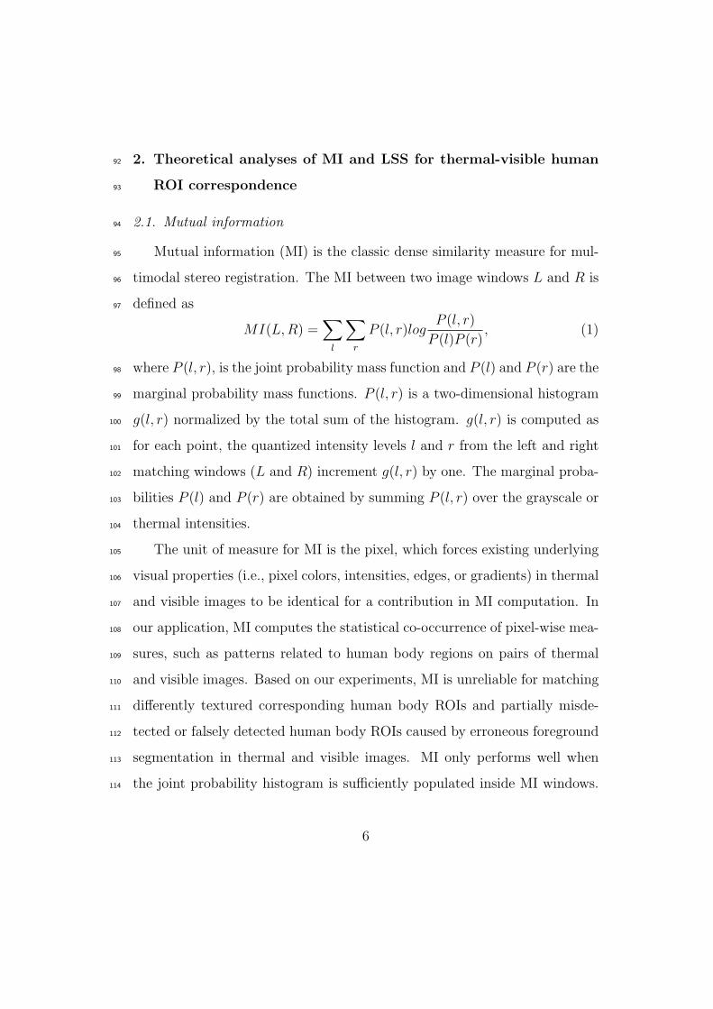
2.1. Mutual information94
Mutual information (MI) is the classic dense similarity measure for mul-95
timodal stereo registration. The MI between two image windows L and R is96
defined as97
MI(L,R) =∑l
∑r
P (l, r)logP (l, r)
P (l)P (r), (1)
where P (l, r), is the joint probability mass function and P (l) and P (r) are the98
marginal probability mass functions. P (l, r) is a two-dimensional histogram99
g(l, r) normalized by the total sum of the histogram. g(l, r) is computed as100
for each point, the quantized intensity levels l and r from the left and right101
matching windows (L and R) increment g(l, r) by one. The marginal proba-102
bilities P (l) and P (r) are obtained by summing P (l, r) over the grayscale or103
thermal intensities.104
The unit of measure for MI is the pixel, which forces existing underlying105
visual properties (i.e., pixel colors, intensities, edges, or gradients) in thermal106
and visible images to be identical for a contribution in MI computation. In107
our application, MI computes the statistical co-occurrence of pixel-wise mea-108
sures, such as patterns related to human body regions on pairs of thermal109
and visible images. Based on our experiments, MI is unreliable for matching110
differently textured corresponding human body ROIs and partially misde-111
tected or falsely detected human body ROIs caused by erroneous foreground112
segmentation in thermal and visible images. MI only performs well when113
the joint probability histogram is sufficiently populated inside MI windows.114
6

Choosing the appropriate window size is not straightforward due to the afore-115
mentioned difficulties. In fact, because of imperfect data, the appropriate size116
might not be available for the computation (e.g. region fragmentation, small117
objects).118
2.2. Local self-similarity119
Local self-similarity (LSS) is a descriptor that capture locally internal120
geometric layout of self-similarities (i.e., edges) within an image region (i.e.,121
human body ROI) while accounting for small local affine deformation. Ini-122
tially, this descriptor has been proposed by Sechtman and Irani [11]. LSS123
describes statistical co-occurrence of small image patch (e.g. 5×5 pixels) in a124
larger surrounding image region (e.g. 40×40 pixels). First, a correlation sur-125
face is computed by a sum of the square differences (SSD) between a small126
patch centered at pixel p and all possible patches in a larger surrounding127
image region. SSD is normalized by the maximum value of the small image128
patch intensity variance and noise (a constant that corresponds to acceptable129
photometric variations in color or illumination). It is defined as130
Sp(x, y) = exp(− SSDp(x, y)
max(varnoise, varpatch)). (2)
Then, the correlation surface is transformed into a log-polar representation131
partitioned into e.g. 80 bins (20 angles and 4 radial intervals). The LSS132
descriptor is defined by selecting the maximal value of each bin that results133
in a descriptor with 80 entries. A LSS descriptor is firstly computed for a134
ROI within an image then it can be compared with other LSS descriptors in135
a second image using a measure such as L1 distance.136
7

Previously, Shechtman and Irani have shown that for matching image137
regions with similar shape/layout but with different direct visual properties138
such as color and edges, LSS is a more reliable similarity metric compared to139
other local image descriptors and match measures such as MI [11]. Shecht-140
man and Irani have also shown that LSS is applicable for image retrieval141
by sketching [11]. In their work, the template image is a sketch of human142
body representing a body pose. The template is used to detect similar hu-143
man body poses in several images with different color and textures. For this144
application, the advantage of LSS is that its unit measure, which is a small145
image patch, contains more meaningful patterns compared to pixel as used146
for MI computations. As it is described in Shechtman and Irani’s work [11],147
this property makes LSS a suitable measure for matching image regions with148
different direct visual properties such as color, edges, or textures, as long as149
they have similar spatial layouts.150
For matching thermal and visible human ROIs, we believe that the same151
LSS property as used for image retrieval by sketching in [11] is applicable. In152
fact, in thermal and visible images, the edges and pixel intensities within cor-153
responding human body ROIs are not identical as it is required for matching154
using MI, but the human body layout is a common indirect visual property155
between thermal and visible corresponding human ROIs.156
Registration accuracy is an important factor for human ROIs registration157
in a scene with multiple people and occlusions. In order to apply LSS as158
a similarity metric, it is required that this descriptor captures local image159
ROI layout within a small surrounding region while considering the required160
image details. Therefore, we experimentally found out that for a close-range161
8
video, a patch of size 3× 3 as a unit measurement within surrounding region162
of 20 × 20 pixels is sufficient to capture meaningful local image patterns of163
human body shape that are mostly belonging to edges. For an LSS-based164
window matching similar to MI-based matching, the overall geometric layout165
within a matching window is captured by a set of LSS descriptors respecting166
the relative geometric positions of the descriptors. Although the window167
sizes have a width smaller than the width of a complete human body and a168
height the same as the human body height; the set of descriptors within a169
window still captures partially body geometric layout. In fact, matching is170
performed by comparing two sets of descriptors belonging to two matching171
windows in thermal and visible images. A good match corresponds to two172
windows where the descriptors are similar both in values and their relative173
geometric positions.174
In order to perform a better matching, we discard the non-informative175
descriptors from each set of descriptors. Non-informative descriptors are176
the ones that do not contain any self-similarities (i.e., the center of a small177
image patch is salient) and the ones that contain high self-similarities (i.e., a178
homogenous region with a uniform texture/color). A descriptor is salient, if179
all its bins’ values are smaller than a threshold. The homogeneity (which also180
cause a non-informative descriptor) is detected using the sparseness measure181
of [16]. The sparseness measure is defined as182
sparseness(X) =
√n− (
∑|xi|)/
√∑x2i√
n− 1(3)
where n is the dimensionality of descriptor x (in our method 80). This func-183
tion evaluates to unity if and only if x contains only a single non-zero compo-184
nent, and takes a value of zero if and only if all components are equal. Dis-185
9
(a) (b)
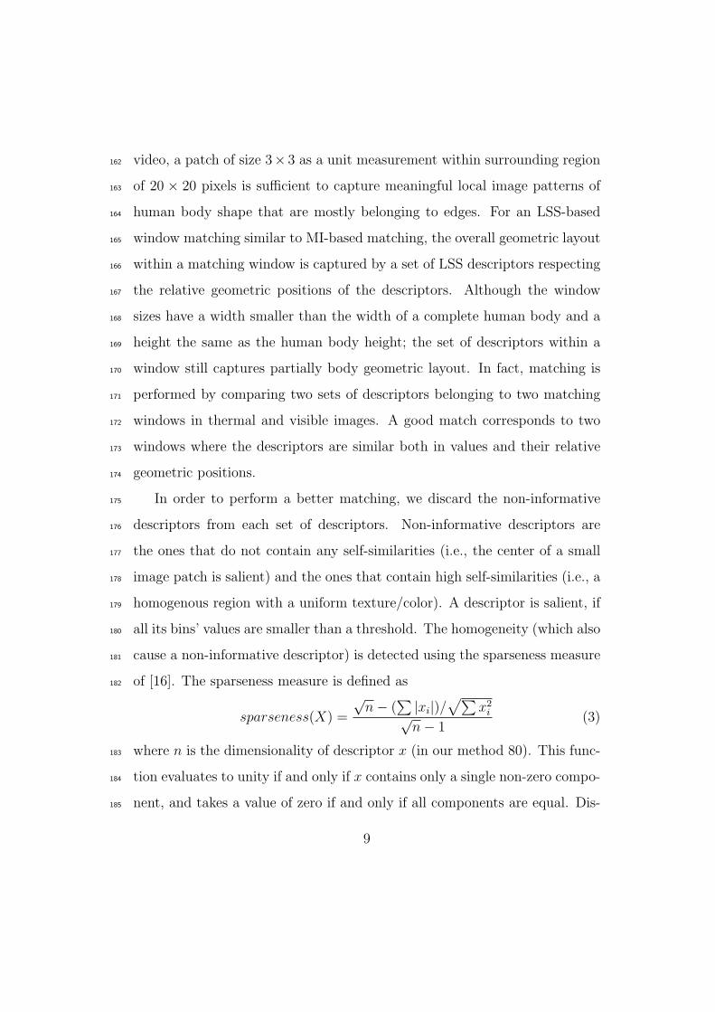
Figure 1: Informative LSS descriptors. (a) Visible and informative LSS descriptors images
(b) Thermal and informative LSS descriptors images.
carding non-informative descriptors is like an implicit segmentation or edge186
detection, which for window matching, increases the discriminative power187
of the LSS measure and avoids ambiguous matching. It is important to188
note that the remaining informative descriptors still form a denser collection189
compared to sparse interest points. Fig. 1 shows pixels having informative190
descriptors (white pixels) for a pair of thermal and visible images. Fig. 1191
is an extreme example of discarding non-informative pixels to highlight by192
filtering out those pixels, the common visual property between thermal and193
visible human ROIs (i.e., human body shape) are obtainable without any194
explicit edge detection or segmentation.195
2.3. Introductory examples of human ROI matching196
In order to illustrate the difficulties of thermal-visible human ROI match-197
ing and the advantages of LSS compared to MI, we present three introductory198
examples of human ROI matching using a simple sliding window matching199
approach and various window sizes. In these examples, matching is per-200
formed by computing the similarity distances of a fixed window on an image201
10
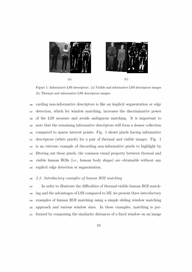
(a) (b)
Figure 2: Matching corresponding textured and uniform regions in visible and thermal
pair of images. (a) Aligned visible and thermal images and (b) Similarity distances of LSS
and MI for disparity interval of [-10,10].
ROI of the visible image with a sliding window on the thermal image within202
a disparity range of [-10, 10], and then choosing the disparity that minimizes203
the similarity distance. In order to simplify the search to 1D, the two images204
were rectified, and then manually aligned so that a disparity of 0 corresponds205
to a ground-truth alignment (more details about multimodal camera calibra-206
tion in section 3.1). We defined the LSS-based similarity distance between207
two windows L and R by the sum of the L1 distances of informative de-208
scriptors within those two windows, and the MI-based similarity distance as209
1−MI(L,R). Fig. 2 shows an example of matching a textured region in the210
visible image with a corresponding uniform region in the thermal image. Fig.211
2 (b) shows the similarity distance results for both MI and LSS over a preset212
disparity range. For LSS, the similarity distance is correctly minimized at213
disparity 0. However for MI, the similarity distance is minimized incorrectly.214
11
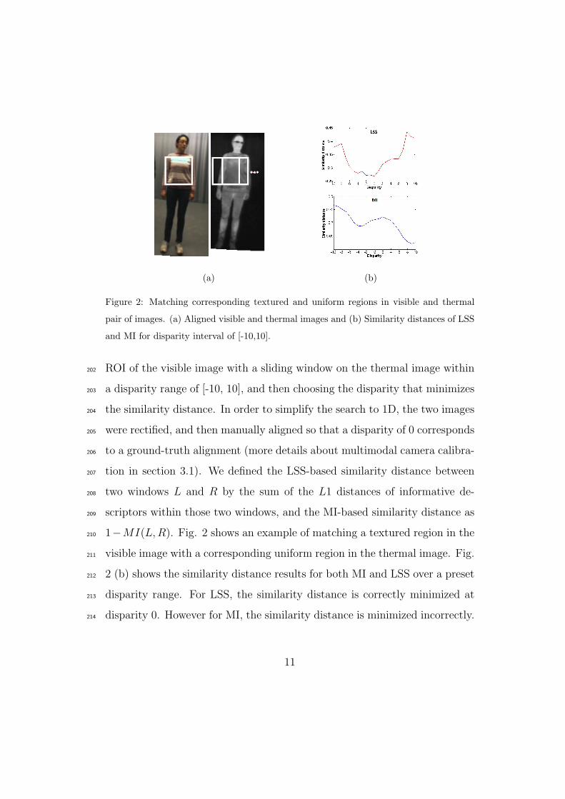
(a) (b)
Figure 3: Matching corresponding regions of visible and thermal within image windows
of size 20× 20 and 50× 50 pixels. (a) Aligned visible and thermal images, (b) Similarity
distances of LSS and MI for disparity interval of [-10,10].
This illustrate that MI is not a robust similarity metric for matching a tex-215
tured region and a uniform region when there are not many similar patterns.216
Fig. 3 shows an example of matching windows of sizes 20 × 20 and 50 × 50217
pixels on a head region. Fig. 3 (b) shows that MI is not a robust mea-218
sure for matching 20 × 20 thermal-visible windows. However, using larger219
window of size 50 × 50 pixels containing more similar patterns and more220
similar spatial layout, MI-based similarity distance is correctly minimized221
at disparity 0. For this example, LSS-based similarity distance is correctly222
minimized at disparity 0 for both matching window sizes which illustrate the223
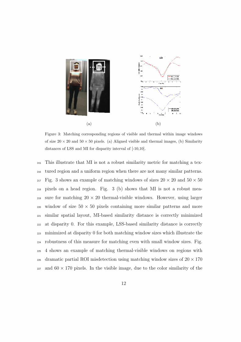
robustness of this measure for matching even with small window sizes. Fig.224
4 shows an example of matching thermal-visible windows on regions with225
dramatic partial ROI misdetection using matching window sizes of 20× 170226
and 60 × 170 pixels. In the visible image, due to the color similarity of the227
12
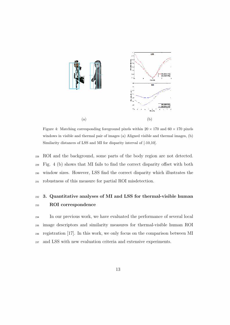
(a) (b)
Figure 4: Matching corresponding foreground pixels within 20 × 170 and 60 × 170 pixels
windows in visible and thermal pair of images (a) Aligned visible and thermal images, (b)
Similarity distances of LSS and MI for disparity interval of [-10,10].
ROI and the background, some parts of the body region are not detected.228
Fig. 4 (b) shows that MI fails to find the correct disparity offset with both229
window sizes. However, LSS find the correct disparity which illustrates the230
robustness of this measure for partial ROI misdetection.231
3. Quantitative analyses of MI and LSS for thermal-visible human232
ROI correspondence233
In our previous work, we have evaluated the performance of several local234
image descriptors and similarity measures for thermal-visible human ROI235
registration [17]. In this work, we only focus on the comparison between MI236
and LSS with new evaluation criteria and extensive experiments.237
13
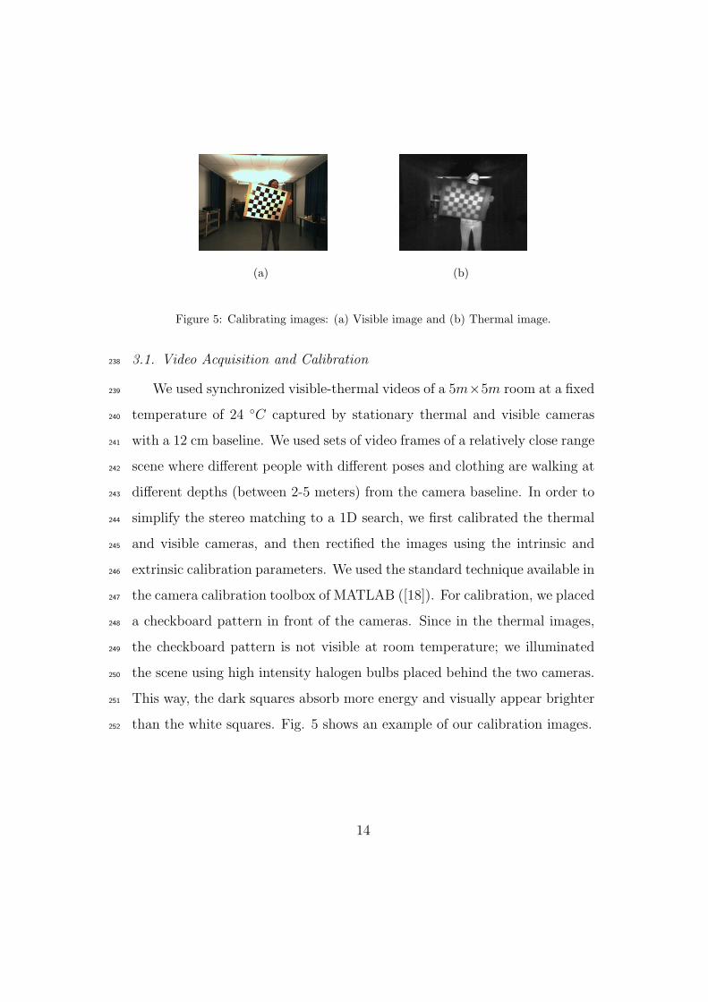
(a) (b)
Figure 5: Calibrating images: (a) Visible image and (b) Thermal image.
3.1. Video Acquisition and Calibration238
We used synchronized visible-thermal videos of a 5m×5m room at a fixed239
temperature of 24 ◦C captured by stationary thermal and visible cameras240
with a 12 cm baseline. We used sets of video frames of a relatively close range241
scene where different people with different poses and clothing are walking at242
different depths (between 2-5 meters) from the camera baseline. In order to243
simplify the stereo matching to a 1D search, we first calibrated the thermal244
and visible cameras, and then rectified the images using the intrinsic and245
extrinsic calibration parameters. We used the standard technique available in246
the camera calibration toolbox of MATLAB ([18]). For calibration, we placed247
a checkboard pattern in front of the cameras. Since in the thermal images,248
the checkboard pattern is not visible at room temperature; we illuminated249
the scene using high intensity halogen bulbs placed behind the two cameras.250
This way, the dark squares absorb more energy and visually appear brighter251
than the white squares. Fig. 5 shows an example of our calibration images.252
14
3.2. Experimental setup253
Our experimental setup is designed to study the efficiency of MI and LSS254
as similarity measures for thermal-visible human ROI registration using real-255
istic videos of multiple people in a close range scene. In our experiment, the256
ROIs within corresponding windows in a pair of thermal and visible images257
might be differently textured or one textured and the other uniform. Win-258
dows are centered at randomly picked points that are located inside visible259
human ROIs. We used a sliding window matching (see section 3.3) to find260
the corresponding image window on the thermal image. The matching pro-261
cess was repeated using three rectangular window sizes of 10 × 130 (small),262
20× 130 (medium), and 40× 130 (large) pixels. The heights of the windows263
are chosen as the maximum possible height of a person in our experimental264
videos. The randomly picked points were located either on textured or tex-265
tureless visible human ROI for relatively near targets (between 2 to 3 meters266
from the camera) or far targets (between 4 to 5 meters). Note that for close-267
range scene monitoring, the scale of targets considerably changes by walking268
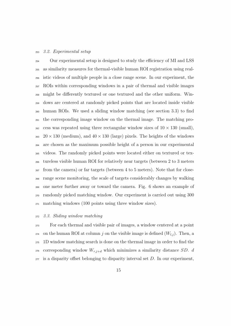
one meter further away or toward the camera. Fig. 6 shows an example of269
randomly picked matching window. Our experiment is carried out using 300270
matching windows (100 points using three window sizes).271
3.3. Sliding window matching272
For each thermal and visible pair of images, a window centered at a point273
on the human ROI at column j on the visible image is defined (Wl,j). Then, a274
1D window matching search is done on the thermal image in order to find the275
corresponding window Wr,j+d which minimizes a similarity distance SD. d276
is a disparity offset belonging to disparity interval set D. In our experiment,277
15
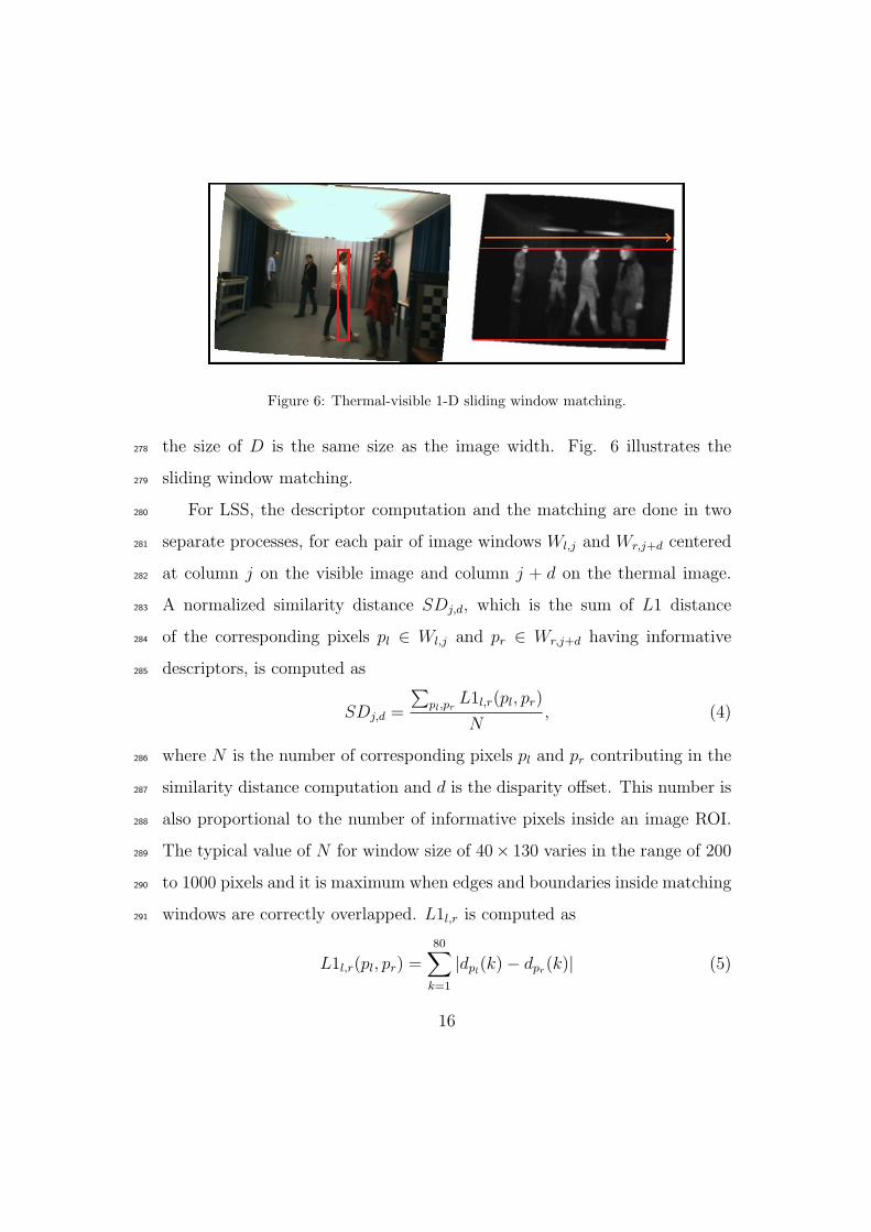
Figure 6: Thermal-visible 1-D sliding window matching.
the size of D is the same size as the image width. Fig. 6 illustrates the278
sliding window matching.279
For LSS, the descriptor computation and the matching are done in two280
separate processes, for each pair of image windows Wl,j and Wr,j+d centered281
at column j on the visible image and column j + d on the thermal image.282
A normalized similarity distance SDj,d, which is the sum of L1 distance283
of the corresponding pixels pl ∈ Wl,j and pr ∈ Wr,j+d having informative284
descriptors, is computed as285
SDj,d =
∑pl,pr
L1l,r(pl, pr)
N, (4)
where N is the number of corresponding pixels pl and pr contributing in the286
similarity distance computation and d is the disparity offset. This number is287
also proportional to the number of informative pixels inside an image ROI.288
The typical value of N for window size of 40× 130 varies in the range of 200289
to 1000 pixels and it is maximum when edges and boundaries inside matching290
windows are correctly overlapped. L1l,r is computed as291
L1l,r(pl, pr) =80∑k=1
|dpl(k)− dpr(k)| (5)
16

where 80 is the number of local self-similarity descriptor bins.292
For MI, SD is defined as293
SDj,d = 1−MI(Wl,j,Wr,j+d), (6)
where MI is the mutual information defined in equation 1. And finally the294
best disparity associated to best matching windows is computed by295
dmin = argmind(SDj,d), d ∈ D. (7)
3.4. Evaluation Criteria296
In our evaluation, we assess the precision-recall and power of discrimina-297
tion of MI and LSS as explained in the following sections.298
3.4.1. Precision and recall299
We used a criterion similar to the one used in [19]. Precision and recall300
are defined as follows:301
precision =#correctmatches
#matchesretrieved(8)
302
recall =#correctmatches
#totalcorrespondences(9)
In our experiment, correctmatches is the number of matches with a dis-303
parity error smaller than 3 pixels with respect to ground-truth and with SD304
(equation 4 or 6) smaller than a threshold t (t varies between minimum pos-305
sible values where matchesretrieved become one and maximum value where306
matchesretrieved become all the matched windows totalcorrespondence).307
totalcorrespondence is a fixed value that corresponds to the number of tested308
windows (i.e., 100 windows of each size). matchesretrieved is the number309
17

of matches with a SD below threshold t. matchesretrieved varies from 1 to310
totalcorrespondences. In a precision and recall curve, a feature with high311
recall value and low precision value means that many correct matches as well312
as many false matches are retrieved. On the other hand, high precision value313
and low recall value means that most matches are correct but many others314
have been missed.315
3.4.2. Power of discrimination316
To assess the reliability of a similarity metric, not only its precision is im-317
portant but also how that similarity metric possesses isolation characteristic318
(power of discrimination) is important as well.319
A similarity metric possesses a high power of discrimination, if its correct320
matches are located on isolated minimums over D (disparity range) and321
SD (equation 4) curve (that is, having SD value much smaller than its322
neighbors). In order to evaluate the isolation characteristic of MI and LSS,323
for their correct matches, we study the shape of SD computed along the324
disparity range D = [q − 20 : q + 20], where q is the position of the global325
minimum (best match). We applied the same measure as in [20]. In order326
to evaluate the isolation of the global minimum, the SD values computed by327
the sliding window matching (section 3.3) are first sorted increasingly and328
are transformed to the interval [0, 1] named SD′. Second, N is the number of329
values in SD′ that are less than a pre-computed small threshold α, ignoring330
the global minimum. α has the same value for evaluating all descriptors331
and measures. Third, a quality measure s (the s value) is computed by332
dividing N by the size of the disparity range. So s = 0 corresponds to333
the most isolated minimum (best performance), and s = 1 corresponds to334
18

the least isolated minimum (flat/constant SD versus d curve). Finally, for335
each correspondence measure, a graph of Accumulated Frequencies (AF )336
of the s values of all matches is computed (In fact AF is the distribution337
of s values belonging to correct matches). Therefore, the correspondence338
measure for which AF reaches a higher value at a smaller s value is the more339
discriminative.340
3.5. Results341
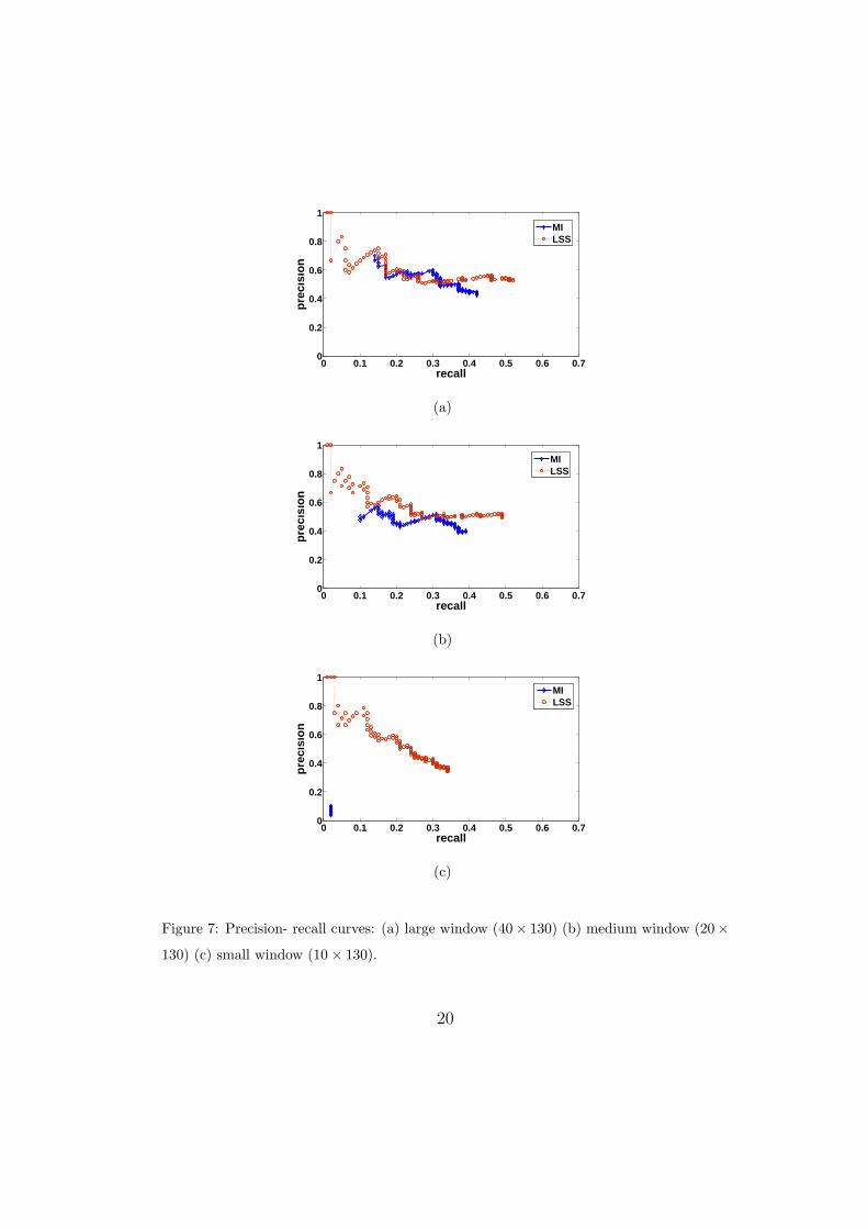
First, we present the evaluation of MI and LSS using the precision and342
recall criterion as explained in section 3.4.1. Fig. 7 shows the precision-recall343
curves of MI and LSS for small, medium, and large window sizes as described344
in section 3.2. Overall, for all the three matching window sizes, LSS achieves345
higher values of recall and precision compared to MI. The largest size window346
achieves better precision than medium and small ones for both MI and LSS.347
However, MI is totally inefficient for small window sizes. This result shows348
the robustness of MI is closely related to the sizes of MI windows, which349
are required to be large enough to sufficiently populate the joint probability350
histogram. On the other hand, the precision of LSS is more consistent for351
three window sizes. For this experiment, we used a simple sliding window352
matching that ignores the occlusions. Using a more appropriate correspon-353
dence algorithm that we propose in section 4, will result in higher matching354
precisions.355
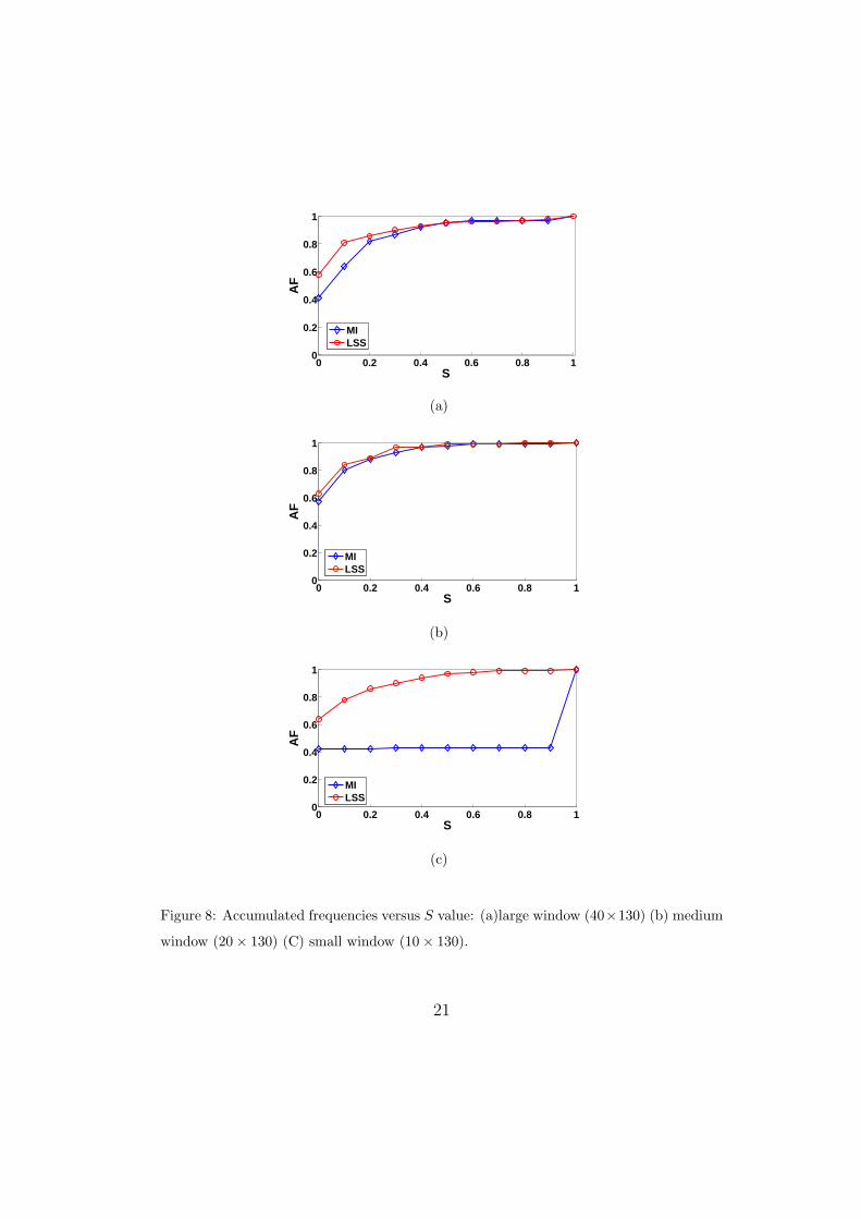
Fig. 8 shows the accumulated frequency distribution of s (details in356
section 3.4.2) obtained for MI and LSS using three window sizes as described357
in section 3.2. It can be seen, for LSS compared to MI, AF starts with a358
higher value and reaches to the higher value for a smaller S value. This shows359
19
0 0.1 0.2 0.3 0.4 0.5 0.6 0.70
0.2
0.4
0.6
0.8
1
recall
pre
cisi
on
MILSS
(a)
0 0.1 0.2 0.3 0.4 0.5 0.6 0.70
0.2
0.4
0.6
0.8
1
recall
pre
cisi
on
MILSS
(b)
0 0.1 0.2 0.3 0.4 0.5 0.6 0.70
0.2
0.4
0.6
0.8
1
recall
pre
cisi
on
MILSS
(c)
Figure 7: Precision- recall curves: (a) large window (40× 130) (b) medium window (20×
130) (c) small window (10× 130).
20
0 0.2 0.4 0.6 0.8 10
0.2
0.4
0.6
0.8
1
S
AF
MILSS
(a)
0 0.2 0.4 0.6 0.8 10
0.2
0.4
0.6
0.8
1
S
AF
MILSS
(b)
0 0.2 0.4 0.6 0.8 10
0.2
0.4
0.6
0.8
1
S
AF
MILSS
(c)
Figure 8: Accumulated frequencies versus S value: (a)large window (40×130) (b) medium
window (20× 130) (C) small window (10× 130).
21

LSS possesses a better isolation characteristics compared to MI.360
Overall, the results show that comparing to MI, LSS is a more reliable361
similarity metric for matching differently textured human ROIs in thermal362
and visible images and it is less restricted by size of matching windows.363
4. LSS-based multimodal ROI registration364
In this section, we describe our novel multimodal ROI registration method365
using LSS. For a pair of thermal and visible video frames, our goal is to366
register the ROIs belonging to moving people in a scene in which they may367
be temporary stationary for a few frames. Our method addresses registration368
of multiple people merged into one ROI with different levels of occlusion and369
with partially erroneous foreground segmentation for realistic thermal-visible370
videos of a close range scene. We assume that each person at each instant lies371
approximately within one depth plane in the scene. Therefore, we propose372
that a natural way for estimating depth planes related to multiple moving373
people is by applying motion segmentation on foreground pixels with the374
assumption that each motion segment belongs to one person in the scene,375
but more than one motion segment may belong to a person.376
We define the multimodal image registration as multiple labeling sub-377
problems. Then, we use the disparity voting matching approach to register378
each individual motion segment rather than a whole foreground blob. Let379
MS be the set of motion segments belonging to moving people in the scene,380
andD be a set of labels corresponding to disparities. Our registration method381
assigns a label dk ∈ D in the range between dmin to dmax to each pixel382
of a motion segment msi ∈ MS. Thus, our registration method has two383
22

main parts: 1) motion segmentation that divides the registration problem384
as multiple labeling sub-problems and 2) disparity assignment which assigns385
disparity to each segment. The two parts of our method are described in the386
subsequent sections.387
4.1. Motion segmentation388
Our motion segmentation has three steps. Firstly, we extract foreground389
pixels using the background subtraction method proposed in [21]. Any back-390
ground subtraction method with a reasonable amount of error is applicable.391
Secondly, we compute the motion vector field for foreground pixels using an392
optical flow method based on block-matching [22]. To speed up the process,393
the optical flow is only computed for regions inside the bounding boxes of394
the union of the foreground masks of two consecutive frames t − 1 and t,395
instead of the whole image. Thirdly, we apply the mean-shift segmentation396
method proposed in [23] for segmenting the motion vector fields computed397
in the previous step and computing a mean velocity vector for the computed398
segments. Mean-shift segmentation is applied on (2+2) feature point dimen-399
sions, where two dimensions are related to spatial dimensions (horizontal and400
vertical directions) and the two others are related to the two motion vector401
components in x and y directions. Applying motion segmentation on ROIs402
results in a set of motion segments S defined as403
SM = {sm1, ..., smm} . (10)
An average mean velocity vector mi is associated to each smi using404
23
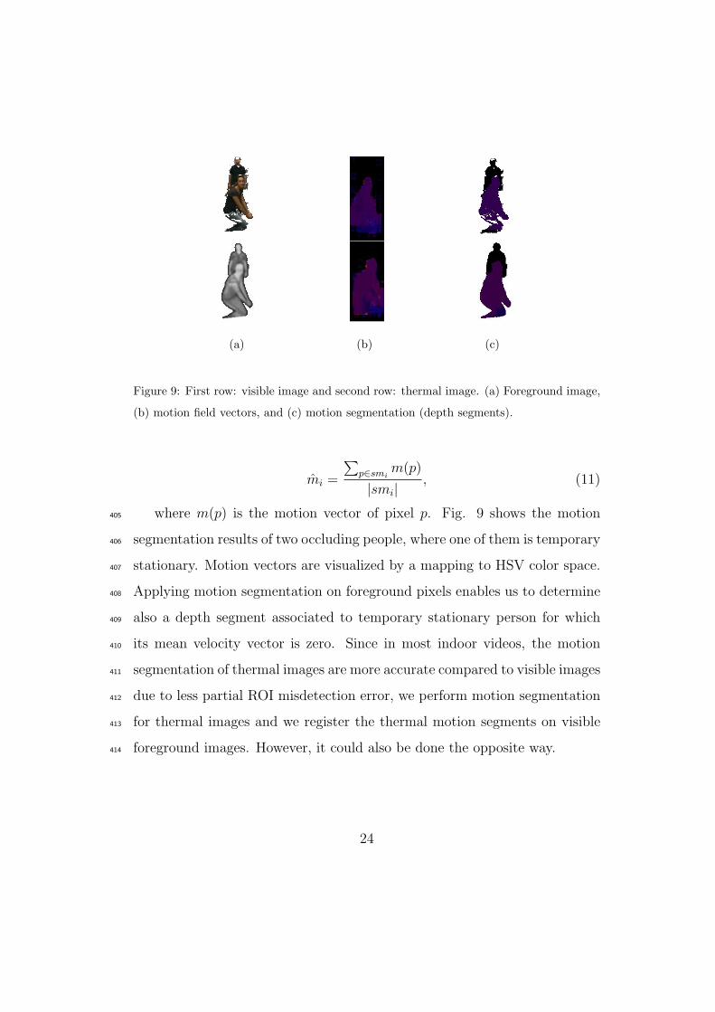
(a) (b) (c)
Figure 9: First row: visible image and second row: thermal image. (a) Foreground image,
(b) motion field vectors, and (c) motion segmentation (depth segments).
mi =
∑p∈smi
m(p)
|smi|, (11)
where m(p) is the motion vector of pixel p. Fig. 9 shows the motion405
segmentation results of two occluding people, where one of them is temporary406
stationary. Motion vectors are visualized by a mapping to HSV color space.407
Applying motion segmentation on foreground pixels enables us to determine408
also a depth segment associated to temporary stationary person for which409
its mean velocity vector is zero. Since in most indoor videos, the motion410
segmentation of thermal images are more accurate compared to visible images411
due to less partial ROI misdetection error, we perform motion segmentation412
for thermal images and we register the thermal motion segments on visible413
foreground images. However, it could also be done the opposite way.414
24

4.2. Disparity assignment415
At this step, we assign disparity to each motion segment individually.416
We use a disparity voting matching approach similar to the one that was417
previously proposed by Krotosky and Trivedi [7]. DV matching assigns one418
single disparity to all the pixels of a column of matching regions. However,419
different disparities can be assigned to two neighboring columns. Krotosky420
and Trivedi DV method uses MI as similarity metric and is performed on421
whole foreground blobs. Their method is able to resolve the horizontal part422
of an occlusion, but fails to assign correct disparity for the vertical part of423
an occlusion (in this case, the pixels of a column for a region associated to424
vertically occluded people should be assigned to a different disparity) (see425
fig. 11). To solve this problem, we propose performing DV on each motion426
segment separately. Moreover, based on our previous experiments, we use427
the informative LSS descriptors as similarity measure.428
4.2.1. LSS-based DV algorithm429
For each smi ∈ S, we build a disparity voting matrix of DVi of size430
(N, dmax − d1 + 1) where N is the number of pixels of smi and [d1 − dmax]431
is a preset disparity range. This procedure is performed by shifting column432
by column Wl,j on the reference image for all the columns j ∈ si, then doing433
window matching, the same as we previously described in section 3.3. Then,434
for each dmin computed by window matching, a vote is added to DVi(pl, dmin)435
for all pl ∈ (Wl,j ∩ si). Since the width of windows are m pixels wide, we436
have m votes for each pixel belonging to si. Finally, the disparity map DMi437
is computed as,438
25

DMi(pl) = argmaxd(Di(pl, d)), (12)
5. Experimental validation and discussion439
We have assessed our registration method with over 5000 video frames440
of up to 5 people with different clothing, various poses, distances to cam-441
eras, and with different level of occlusions. In these experiments, we used442
the same experimental setup as described previously in section 3.1. The first443
test video was captured during summer with people having lighter clothes444
(light clothes results in less heat patterns on the body in infrared) and with445
a fair amount of textures inside human ROIs in thermal and visible im-446
ages. The background subtraction errors were mostly misdetection errors.447
Our other two test videos were captured during winter with people wearing448
winter clothes (thick clothes results in more heat patterns on the body in449
infrared), which causes patterns inside human body ROIs. The background450
subtraction results in our winter videos include both misdetection errors and451
falsely detected region as foreground. The disparity range was between 5 to452
50 pixels.453
Fig. 10 illustrates successful registrations with our method in one of our454
winter videos for three frames of people in different levels of occlusions.455
5.1. Comparison of DV correspondence and our correspondence algorithm456
In order to demonstrate the accuracy improvement of our method com-457
pared to a state-of-the-art disparity voting algorithm (DV) [7] in handling458
occlusions, we quantitatively compared our disparity results using motion459
26
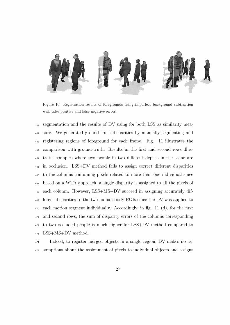
Figure 10: Registration results of foregrounds using imperfect background subtraction
with false positive and false negative errors.
segmentation and the results of DV using for both LSS as similarity mea-460
sure. We generated ground-truth disparities by manually segmenting and461
registering regions of foreground for each frame. Fig. 11 illustrates the462
comparison with ground-truth. Results in the first and second rows illus-463
trate examples where two people in two different depths in the scene are464
in occlusion. LSS+DV method fails to assign correct different disparities465
to the columns containing pixels related to more than one individual since466
based on a WTA approach, a single disparity is assigned to all the pixels of467
each column. However, LSS+MS+DV succeed in assigning accurately dif-468
ferent disparities to the two human body ROIs since the DV was applied to469
each motion segment individually. Accordingly, in fig. 11 (d), for the first470
and second rows, the sum of disparity errors of the columns corresponding471
to two occluded people is much higher for LSS+DV method compared to472
LSS+MS+DV method.473
Indeed, to register merged objects in a single region, DV makes no as-474
sumptions about the assignment of pixels to individual objects and assigns475
27

a single disparity to each column inside an ROI based on a maximization of476
the number of votes. In their matching approach [7], if a column of pixels477
belongs to different objects at different depth in the scene, the vote only478
goes for one of them based on WTA approach. However, in our registration479
method, motion segmentation gives a reasonable estimate of moving regions480
belonging to people in the scene, and applying the DV matching on each mo-481
tion segment gives more accurate results since it is less probable that pixels482
in one column belongs to more than one object. Therefore, in the worst case,483
even with erroneous motion segmentation, our method will have at minimum484
the same accuracy as the DV algorithm.485
Fig. 11, last row, illustrates the example of multiple occluding people. Al-486
though LSS+MS+DV registration results are not perfect because few small487
motion segments resulting from over segmentation were not matched cor-488
rectly still the results are more accurate than for LSS+DV. Accordingly, in489
Fig. 11 (d), last row, the sums of disparity error for columns related to verti-490
cal occlusion is higher for LSS+DV compared to LSS+MS+DV. However, it491
is noticeable that in some columns, LSS+MS+DV has slightly higher errors492
caused by small motion segments misalignment.493
Fig. 12 illustrates other registration results with LSS+MS+DV and494
LSS+DV. It is observable, that for LSS+DV method, the object misalign-495
ments happen where there are vertical occlusions while our method performs496
accurately in such a case.497
28
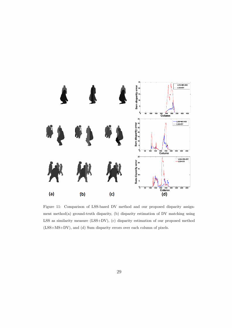
Figure 11: Comparison of LSS-based DV method and our proposed disparity assign-
ment method(a) ground-truth disparity, (b) disparity estimation of DV matching using
LSS as similarity measure (LSS+DV), (c) disparity estimation of our proposed method
(LSS+MS+DV), and (d) Sum disparity errors over each column of pixels.
29

(a)
(b)
Figure 12: Comparison of LSS+DV and LSS+MS+DV detailed registration: (a) LSS+DV
registration and (b) LSS+MS+DV registration.
5.2. Comparison of our LSS-based registration with the state-of-the-art MI-498
based registration499
In order to demonstrate the improvement of our LSS-based registration500
method LSS+MS+DV compared to the state-of-the-art MI-based registra-501
tion method, MI+DV, proposed by Krotosky and Trivedi [7], we qualitatively502
and quantitatively compared the two methods. Fig. 14 illustrates four exam-503
ples of the disparity computation and the image registration results obtained504
using the two methods for our summer video. Note that our results are more505
accurate, especially for occlusions. Fig. 15 illustrates four examples for win-506
ter video 1. Note that MI+DV results are significantly poorer. These results507
demonstrate that for videos where there are falsely detected region as fore-508
ground and high differences of patterns inside human body ROIs, MI is not509
a reliable similarity measure. In contrast, LSS performs very well, except for510
30
0 100 200 300 400 500 600 7000
0.2
0.4
0.6
0.8
1
Frame
Ove
rlap
pin
g e
rro
r
LSS+MS+DVMI+DV
(a)
0 500 1000 1500 2000 2500 3000 35000
0.2
0.4
0.6
0.8
1
Frame
Ove
rlap
pin
g e
rro
r
LSS+MS+DVMI+DV
(b)
0 200 400 600 800 10000
0.2
0.4
0.6
0.8
1
Frame
Ove
rlap
pin
g e
rro
r
LSS+MS+DVMI+DV
(c)
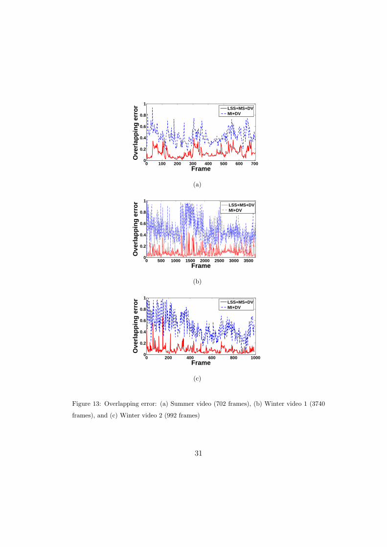
Figure 13: Overlapping error: (a) Summer video (702 frames), (b) Winter video 1 (3740
frames), and (c) Winter video 2 (992 frames)
31
few misalignments which occur for very small motion segments.511
For a quantitative evaluation of the two registration methods, we defined512
an overlapping error that gives a quantitative estimate of the registration513
accuracy. The overlapping error is defined as,514
E = 1− Nv∩t
Nt
, (13)
where Nv∩t is the number of overlapping aligned thermal foreground pix-515
els on visible foreground pixels and Nt is the number of thermal foreground516
pixels. The best performance with zero overlapping error is when all the517
thermal pixels on the reference image have corresponding visible pixels on518
the second image. Note that our registration results are aligned thermal on519
visible images. This evaluation measure includes the background subtraction520
errors and also ignores misaligned thermal pixels which have falsely matched521
visible foreground pixels. However, since for both methods the background522
subtraction errors are included in the overlapping error, the differences be-523
tween the two methods errors are still a good indicator for comparing overall524
registration accuracies for a large numbers of frames. Fig 13 illustrates the525
overlapping error using our LSS+MS+DV and MI+DV [7] methods for sum-526
mer and winter videos. Based on table 1, the differences of mean overlapping527
error for the two methods over all frames (fig 13 (a)) are 0.30 for the sum-528
mer video (fig 13 (a)), and 0.40 and 0.41 for the winter videos, (fig 13 (b)529
and (c), respectively). Also, table 1 shows the standard deviation of over-530
lapping. The fluctuation of overlapping error for LSS+MS+DV method is531
much less than for MI+DV [7] method, especially for winter videos because532
of larger difference in textures on the objects. These results demonstrate533
32

that our method performs more accurately and more consistently compared534
to MI+DV [7] method, especially for winter videos, in accordance with our535
qualitative results and previous discussions.536
Table 1: Overlapping error (OE) for disparity voting (MI) and our proposed algorithm
(LSS) with multiple people in the scene: frames with occlusion. SV: summer video, WV1
and WV2: winter videos, NO: number of objects, NF: number of frames, SM: similarity
metric, and % OE (Ave - Std): average and standard deviation of overlapping error.
Video NO NF SM OE (Ave - Std)
SV 4 702 LSS 0.13 - 0.07
MI 0.43 - 0.12
WV1 4 3740 LSS 0.09 - 0.06
MI 0.49 - 0.17
WV2 5 992 LSS 0.07 - 0.07
MI 0.48 - 0.19
6. Conclusion537
In this paper, we applied LSS as a multimodal dense stereo correspon-538
dence measure and shown its advantages compared to MI, the most com-539
monly used multimodal stereo correspondence measure in the state-of-the-540
art for human monitoring applications. We also proposed an LSS-based541
registration method, which addresses the accurate registration of regions as-542
sociated to occluded people in different depths in the scene. In our results,543
we have shown the improvement of our registration method over the DV544
method proposed by [7]. Moreover, we have shown that our method signifi-545
cantly outperforms the state-of-the-art MI-based registration method in [7].546
33

Figure 14: Comparison of MI+DV method in [7] and our proposed method LSS+MS+DV
for our summer video using imperfect foreground segmentation (mainly misdetection).
(a) visible image, (b) visible foreground segmentation, (c) thermal image, (d) thermal
foreground segmentation, (e) MI+DV disparity image, (f) LSS+MS+DV disparity image,
(g) MI+DV registration, and (h) LSS+MS+DV registration.
34
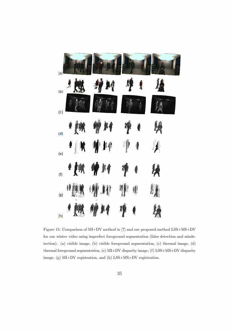
Figure 15: Comparison of MI+DV method in [7] and our proposed method LSS+MS+DV
for our winter video using imperfect foreground segmentation (false detection and misde-
tection). (a) visible image, (b) visible foreground segmentation, (c) thermal image, (d)
thermal foreground segmentation, (e) MI+DV disparity image, (f) LSS+MS+DV disparity
image, (g) MI+DV registration, and (h) LSS+MS+DV registration.
35
As future direction for this work, we are working on improving the motion547
segmentation results to obtain more accurate segments and to avoid over548
segmentation.549
References550
[1] Z. Zhu, T. Huang, Multimodal surveillance: an introduction, in: Com-551
puter Vision and Pattern Recognition, 2007. CVPR ’07. IEEE Confer-552
ence on, 2007, pp. 1 –6.553
[2] R. Collins, A. Lipton, H. Fujiyoshi, T. Kanade, Algorithms for cooper-554
ative multisensor surveillance, Proceedings of the IEEE 89 (10) (2001)555
1456 –1477.556
[3] D. Socolinsky, Design and deployment of visible-thermal biometric557
surveillance systems, in: Computer Vision and Pattern Recognition,558
2007. CVPR ’07. IEEE Conference on, 2007, pp. 1 –2.559
[4] J. W. Davis, V. Sharma, Background-subtraction using contour-based560
fusion of thermal and visible imagery, Comput. Vis. Image Underst. 106.561
[5] A. Leykin, Thermal-visible video fusion for moving target tracking and562
pedestrian classification, in: In Object Tracking and Classification in563
and Beyond the Visible Spectrum Workshop at the International Con-564
ference on Computer Vision and Pattern Recognition, 2007, pp. 1–8.565
[6] J. Han, B. Bhanu, Fusion of color and infrared video for moving human566
detection, Pattern Recognition 40 (6) (2007) 1771 – 1784.567
36

[7] S. J. Krotosky, M. M. Trivedi, Mutual information based registration568
of multimodal stereo videos for person tracking, Computer Vision and569
Image Understanding 106 (2-3) (2007) 270 – 287.570
[8] H.-M. Chen, P. Varshney, M.-A. Slamani, On registration of regions571
of interest (roi) in video sequences, in: IEEE Conference on Advanced572
Video and Signal Based Surveillance (AVSS 2003), 2003, pp. 313 – 318.573
[9] C. Fookes, A. Maeder, S. Sridharan, J. Cook, Multi-spectral stereo image574
matching using mutual information, in: 3D Data Processing, Visualiza-575
tion and Transmission, 2004. 3DPVT 2004. Proceedings. 2nd Interna-576
tional Symposium on, 2004, pp. 961 – 968.577
[10] G. Egnal, Mutual information as a stereo correspondence measure, Tech.578
Rep. MS-CIS-00-20, University of Pennsylvania.579
[11] E. Shechtman, M. Irani, Matching local self-similarities across images580
and videos, in: IEEE Conference on Computer Vision and Pattern581
Recognition (CVPR 2007), 2007, pp. 1 –8.582
[12] S. Walk, N. Majer, K. Schindler, B. Schiele, New features and insights583
for pedestrian detection, in: IEEE Conference on Computer Vision and584
Pattern Recognition (CVPR 2007), 2010, pp. 1030–1037.585
[13] J. Yang, Y. Li, Y. Tian, L. Duan, W. Gao, Group-sensitive multiple586
kernel learning for object categorization, in: IEEE 12th International587
Conference on Computer Vision (ICCV 2009), 2009, pp. 436 –443.588
[14] A. Vedaldi, V. Gulshan, M. Varma, A. Zisserman, Multiple kernels for589
37
object detection, in: IEEE 12th International Conference on Computer590
Vision (ICCV 2009), 2009, pp. 606 –613.591
[15] A. Torabi, G.-A. Bilodeau, Local self-similarity as a dense stereo corre-592
spondence measure for themal-visible video registration, in: Computer593
Vision and Pattern Recognition Workshops (CVPRW), 2011 IEEE Com-594
puter Society Conference on, 2011, pp. 61 –67.595
[16] P. O. Hoyer, P. Dayan, Non-negative matrix factorization with sparse-596
ness constraints, Journal of Machine Learning Research 5 (2004) 1457–597
1469.598
[17] A. Torabi, M. Najafianrazavi, G. Bilodeau, A comparative evaluation599
of multimodal dense stereo correspondence measures, in: Robotic and600
Sensors Environments (ROSE), 2011 IEEE International Symposium on,601
2011, pp. 143 –148.602
[18] J. Heikkila, O. Silven, A four-step camera calibration procedure with603
implicit image correction, in: Computer Vision and Pattern Recognition,604
1997. Proceedings., 1997 IEEE Computer Society Conference on, 1997,605
pp. 1106 –1112.606
[19] A. Gil, O. M. Mozos, M. Ballesta, O. Reinoso, A comparative evaluation607
of interest point detectors and local descriptors for visual slam, Mach.608
Vision Appl. 21 (2010) 905–920.609
[20] R. Mayoral, M. Aurnhammer, Evaluation of correspondence errors for610
stereo, Pattern Recognition, International Conference on 4 (2004) 104–611
107.612
38
[21] B. Shoushtarian, H. E. Bez, A practical adaptive approach for dynamic613
background subtraction using an invariant colour model and object614
tracking, Pattern Recogn. Lett. 26 (1) (2005) 5–26.615
[22] A. Ogale, Y. Aloimonos, A roadmap to the integration of early visual616
modules, International Journal of Computer Vision 72 (2007) 9–25.617
[23] D. Comaniciu, P. Meer, Mean shift analysis and applications, in: The618
Proceedings of the Seventh IEEE International Conference on Computer619
Vision, (ICCV 1999), Vol. 2, 1999, pp. 1197 –1203 vol.2.620
39