Embed Size (px)
Citation preview

DOT/FAA/AR-08/35 Air Traffic Organization Operations Planning Office of Aviation Research and Development Washington, DC 20591
Handbook for Networked Local Area Networks in Aircraft October 2008 Final Report This document is available to the U.S. public through the National Technical Information Service (NTIS), Springfield, Virginia 22161.
U.S. Department of Transportation Federal Aviation Administration

NOTICE
This document is disseminated under the sponsorship of the U.S. Department of Transportation in the interest of information exchange. The United States Government assumes no liability for the contents or use thereof. The United States Government does not endorse products or manufacturers. Trade or manufacturer's names appear herein solely because they are considered essential to the objective of this report. This document does not constitute FAA certification policy. Consult your local FAA aircraft certification office as to its use. This report is available at the Federal Aviation Administration William J. Hughes Technical Center’s Full-Text Technical Reports page: actlibrary.tc.faa.gov in Adobe Acrobat portable document format (PDF).

Technical Report Documentation Page
1. Report No.
DOT/FAA/AR-08/35
2. Government Accession No. 3. Recipient's Catalog No.
4. Title and Subtitle
HANDBOOK FOR NETWORKED LOCAL AREA NETWORKS IN AIRCRAFT
5. Report Date
October 2008 6. Performing Organization Code
7. Author(s)
Eric Fleischman
8. Performing Organization Report No.
9. Performing Organization Name and Address
The Boeing Company P.O. Box 3707, MC 7L-49 Seattle, WA 98124-2207
10. Work Unit No. (TRAIS)
11. Contract or Grant No.
DTFACT-05-C-00003 12. Sponsoring Agency Name and Address
U.S. Department of Transportation Federal Aviation Administration Air Traffic Organization Operations Planning Office of Aviation Research and Development Washington, DC 20591
13. Type of Report and Period Covered
Final Report
14. Sponsoring Agency Code
AIR-120 15. Supplementary Notes
The Federal Aviation Administration Airport and Aircraft Safety R&D Division Technical Monitor was Charles Kilgore. 16. Abstract
This Handbook summarizes the results of the Federal Aviation Administration (FAA) networked local area network (LAN) study, which addresses potential safety impacts introduced by networking LANs onboard aircraft. Interconnecting previously isolated components on aircraft increases the complexity of unintended interactions between components and provides potential new access points that could be exploited to cause harm. This Handbook addresses the potential security vulnerabilities introduced by networking LANs, the safety affects of security failures, and a process for designing and certifying LANs on aircraft to ensure the safety of these new aircraft systems. This Handbook extends the current FAA safety assurance processes into airborne networked environments by leveraging the Biba Integrity Model. It builds upon existing FAA studies that articulate mechanisms to integrate RTCA/DO-178B and common criteria processes for the National Airspace System. This approach creates a safety-oriented airborne network architecture that is built upon DO-178B and ARP 4754 safety mechanisms. This Handbook discusses specific design and configuration issues upon which the civil aviation community will need to establish consistent consensus positions if the recommended architecture is to be seamlessly deployed into operational environments. 17. Key Words
Local area network, Network, Aircraft safety, Aircraft security
18. Distribution Statement
This document is available to the U.S. public through the National Technical Information Service (NTIS), Springfield, Virginia 22161.
19. Security Classif. (of this report) Unclassified
20. Security Classif. (of this page) Unclassified
21. No. of Pages 111
22. Price
Form DOT F 1700.7 (8-72) Reproduction of completed page authorized

TABLE OF CONTENTS
Page
EXECUTIVE SUMMARY xi
1. INTRODUCTION 1
1.1 Background 1 1.2 Purpose 4 1.3 Scope 4 1.4 Organization 5
2. NETWORK RISKS 5
2.1 Risks Come From Both Direct and Indirect Connectivity 6 2.2 Internal, External, and Client-Side Attacks From Devices and Humans 7 2.3 Commercial Off-the-Shelf Vulnerabilities in a Networked Environment 9 2.4 Evolving Software Behavior: Pre-Attack, Attack, and Post-Attack 16 2.5 Management Oversight and Assurance 16
3. NETWORK SECURITY DEFENSES 18
3.1 Defense-in-Depth 18 3.2 Airborne Network Security Requirements 20
3.2.1 Integrity 21 3.2.2 Availability 23 3.2.3 Authentication 24 3.2.4 Confidentiality 25 3.2.5 Nonrepudiation 25
3.3 Partitioning Network Systems 25 3.4 Extending Policy Into Arbitrarily Complex Network Systems 30
4. EXTENDING THE CURRENT FAA CERTIFICATION ENVIRONMENT 34
4.1 Extending ARP 4754 Into Networked Environments 38 4.2 Extending DO-178B Into Networked Environments 39 4.3 Similar DoD and FAA Certification Environments 41 4.4 Relating Safety Classification Levels to the Common Criteria 45
5. EXEMPLAR AIRBORNE NETWORK ARCHITECTURE 48
5.1 System Security Engineering Methodology 48 5.2 Applying the SSE Methodologies to Airborne Networks 52
iii

iv
5.3 Exemplar Airborne Network Architecture 54 5.3.1 The VPN Encapsulation Method 56 5.3.2 Encapsulation Gateways 61 5.3.3 Physical Security 62 5.3.4 Packet Filter 62 5.3.5 Firewall 63 5.3.6 The ASBR 63 5.3.7 High-Assurance LAN 64 5.3.8 Quality of Service 64 5.3.9 Air-to-Ground and Air-to-Air Communications 64
6. AIRBORNE NETWORK DESIGN CONSIDERATIONS 65
6.1 Aircraft Design Targets 66 6.2 Integrated Modular Avionics Design Issues 69 6.3 Maintenance Issues 70 6.4 Issues for Updating Airborne Software 71 6.5 Handling Security Breaches 73 6.6 Network Management 75
7. THE NAS DESIGN CONSIDERATIONS FOR COMMUNICATIONS
TO AIRCRAFT 77
7.1 Identity 80 7.2 Internet Protocol Addressing 81
7.2.1 Aircraft and Network Mobility 82 7.2.2 Aircraft as a Node 83 7.2.3 Multilevel Network Systems 84
7.3 Routing 84 7.4 Authentication and Authorization 87 7.5 Internet Protocol Family Security 87
8. DESIGN CONSIDERATIONS FOR AIRBORNE NETWORK SOFTWARE 89
9. AIRBORNE NETWORK CERTIFICATION CONSIDERATIONS 90
10. REFERENCES 91

LIST OF FIGURES Figure Page 1 Threat Agents in a Networked Environment 9
2 A Sample Deployment 13
3 Overlapping Defense-in-Depth IA Systems 19
4 Sample Defense-in-Depth Technologies 19
5 Control Life Cycle 20
6 Code- and Document-Signing Process 22
7 Code- and Document-Signing Verification Process 22
8 Interfaces Between Customer and Service Provider Networks 27
9 Example of VPN Encapsulation Using IPsec 28
10 Customer’s L3VPN Protocol Stack as Seen Within the Network Service Provider’s Network 30
11 Bell-LaPadula Confidentiality and Biba Integrity Models Compared 32
12 Three Different Software Certification Environments 35
13 DO-178B Classifications Using Biba Integrity Model 44
14 Gap Analysis in the Alves-Foss, et al. Study 48
15 Security Engineering Process 49
16 Secure Generic Airborne Network Design (High-Level View) 55
17 How Design Addresses Network Risks 55
18 How Design Addresses Network Threats 56
19 Close-Up of How Encapsulation is Accomplished 57
20 The VPN Interconnecting Two Sites 58
21 Notional Networked Aircraft Architecture 66
22 Generic Future Communication System Physical Architecture 67
v

23 Alternative Notional Aircraft Architecture 67
24 Both Target Architectures Have Similar Security Profiles 68
25 Notional IMA Design 70
26 Another Notional IMA Design 70
27 Sample Airborne Network 76
28 The IP Topology Hierarchy 79
vi

vii
LIST OF TABLES
Table Page 1 Comparison of Safety Levels to Security Classifications 42

LIST OF ACRONYMS AND ABBREVIATIONS AC Advisory Circulars AFDX Avionics full duplex switched (Ethernet) AJ Anti-jamming AS Autonomous system ASBR Autonomous system boundary router (alternatively: AS border router) ATN Aeronautical Telecommunications Network BGP Border gateway protocol CA Certificate authority CC Common criteria CE Customer edge CERT Computer Emergency Response Team CIDR Classless interdomain routing COMSEC Communications security CONOPS Concept of Operations COTS Commercial off-the-shelf CPU Central processing unit CRC Cyclic redundancy check DoD Department of Defense DoDI Department of Defense Instruction DoS Denial of Service DSS Digital Signature Standard EAL Evaluation Assurance Level EGP Exterior gateway protocol ESP Encapsulating security payload FAA Federal Aviation Administration FIPS Federal Information Processing Standard GIG Global information grid HAG High-assurance guard HTTP Hypertext transfer protocol IA Information assurance IATF Information Assurance Technical Framework IDS Intrusion detection system IETF Internet Engineering Task Force IGP Interior gateway protocol IMA Integrated modular avionics IP Internet protocol IPsec Internet protocol security ISP Internet service provider IS-IS Intermediate system to intermediate system IT Information technology L2VPN Layer 2 virtual private network L3VPN Layer 3 virtual private network LAN Local area network
viii

MAC Mission assurance category MANET Mobile ad hoc networking MIP Mobile internet protocol MPLS Multiprotocol label switching MSLS Multiple single-levels of security NAS National Airspace System NASA National Aeronautics and Space Administration NAT Network Address Translator NEMO Network mobility NIDS Network intrusion detection system NSA National Security Agency OS Operating system OSI Open system interconnect OSPF Open shortest path first PE Provider edge PKI Public key infrastructure QoS Quality of service RAM Random access memory RFC Request for Comment (i.e., Publications of the IETF) SA Security association SATS Small Aircraft Transportation System SLA Service Level Agreement SNMP Simple network management protocol SPD Security policy database SSE System Security Engineering SWAP Size, weight, and power SYN Synchronous (bit) TCP Transmission control protocol TTL Time-to-live VPN Virtual private network
ix/x

EXECUTIVE SUMMARY This Handbook summarizes the results of the Federal Aviation Administration (FAA)-funded study “Software and Digital Systems Safety Research Task 002—Local Area Networks in Aircraft.” This study investigated the methodologies for identifying and mitigating potential security risks of onboard networks that could impact safety. It also investigated techniques for mitigating security risks in the certification environment. This Handbook organizes the networked local area network study results into sections that are tailored for the four target audiences of this document: • Airborne network design engineers. • Design engineers for national airspace systems that will communicate with aircraft. • Developers of airborne software. • Individuals involved with the certification of airborne software systems. Current FAA safety assurance processes for airborne systems are based on ARP 4754, ARP 4761, and Advisory Circulars (AC) (e.g., AC 25.1309-1A and AC 23.1309-1C). FAA software assurance is based on compliance with RTCA/DO-178B that guides software development processes. Complex electronic hardware design assurance is based on DO-254. ARP 4754 extends the DO-178B software assurance process to address the additional safety issues that arise when software is embedded into highly integrated or complex airborne system relationships. Connecting airborne software within network systems represents an extension of the ARP 4754 environment to include networked items that share limited common functional relationships with each other. This is because networks connect entities or components of a system into a common networked system regardless of the original functional intent of the system design (e.g., multiple aircraft domains can be connected by a common network system). Networks are inherently hostile environments because every network user, which includes both devices (and their software) and humans, is a potential threat to that environment. Networked entities form a fate-sharing relationship with each other because any compromised network entity can, theoretically, be used to attack other networked entities or their shared network environment. Networked environments and the entities that comprise them need to be protected from three specific classes of threat agents: (1) the corrupted or careless insider, (2) the hostile outsider, and (3) client-side attacks. Because of these dangers, ARP 4754 needs to be extended for networked environments by ensuring network security protection and function/component availability and integrity. This, in turn, implies the need to strategically deploy information assurance security controls within network airborne systems. Safety and security have, therefore, become intertwined concepts within networked airborne environments. Security engineering addresses the potential for failure of security controls caused by malicious actions or other means. Safety analysis focuses on the effects of failure modes. The two concepts (safety and security) are, therefore, directly related through failure effects. A shortcoming of either a safety process or a security process may cause a failure in a respective system safety or security mechanism, with possible safety consequences to the aircraft, depending on the specific consequence of that failure.
xi

xii
Previous studies sought to address airborne safety and security by correlating DO-178B safety processes with common criteria security processes. This correlation produces necessary, but inadequate, results. It is inadequate because it lacks mathematical rigor and, therefore, produces ad hoc conclusions. The results are ad hoc because even when safety and security are correlated they are, nevertheless, distinct concepts from each other, and address very different concerns. This Handbook states that the primary issue impacting network airborne system safety is how to extend existing ARP 4574, ARP 4761, DO-178B, and DO-254 assurance guidance processes into networked systems and environments in a mathematically viable manner. This Handbook recommends that these processes can be extended into arbitrarily vast network environments in a mathematically viable manner by using the Biba Integrity Model framework. This Handbook maps current DO-178B and ARP 4754 processes into the Biba Integrity Model framework using well-established system security engineering processes to define airborne safety requirements. It applies best current information assurance techniques upon those airborne safety requirements to create a generic airborne network architecture. This Handbook identifies a generic airborne network architecture that implements these concepts (i.e., current FAA safety policies within a Biba Integrity Model framework). It then discusses specific deployment issues upon which the civil aviation community needs to establish consensus positions if this architecture is to be seamlessly deployed into operational environments.

1. INTRODUCTION.
This Handbook summarizes the Federal Aviation Administration (FAA) study “Networked Local Area Networks (LANs) in Aircraft: Safety, Security and Certification Issues, and Initial Acceptance Criteria” [1]. This study investigates the methodologies for identifying and mitigating potential security risks of onboard networks that could impact safety. It also investigates techniques for mitigating security risks in the certification environment. 1.1 BACKGROUND.
Visionaries anticipate forces that could motivate future airborne system designs to replace today’s diverse databus systems within aircraft, including many of their current constraints (e.g., access point limitations, proprietary protocols, labeling, and mitigations such as cyclic redundancy checks), with airplane-appropriate LAN technologies that support standard Internet protocol (IP)-based communications. For example, AR-05/52 “Safety and Certification Approach for Ethernet-Based Aviation Databuses” [2] concluded that Ethernet-based LANs could be appropriate to serve as aviation databuses if they use
“a switched Ethernet topology along with traffic regulation, bandwidth restriction (guarantee and control of bandwidth allocation), and call admission control.”
Coupled with the linkage of aircraft systems via a common network system is a growing perception of the desirability to base future civil aviation communications upon IPs and to enhance air-to-ground and air-to-air communication systems and processes as well as to more closely integrate airborne systems with National Airspace System (NAS) systems. For example: • Integrating multiple databus systems into onboard LAN(s) is expected to reduce aircraft
size, weight, and power (SWAP) overheads, thereby improving aircraft flight performance parameters.
• Next generation aircraft display systems may want to combine map and air traffic data,
terrain information, weather radar returns, information on man-made obstacles, and imagery on the airport environment. This would require fusing data from sources that are not currently associated together. It would also necessitate the support of high-bandwidth data communications internally within the aircraft, as well as air-to-ground and within the NAS.
• National Aeronautics and Space Administration (NASA) Small Aircraft Transportation
System (SATS) is investigating mechanisms that would enable small aircraft to fly to and from the 5400 small airports that are not currently being used for reliable public transportation. “A key to implanting SATS is a robust and extremely reliable automated communications system. The system must be capable of passing large amounts of data between aircraft and ground systems as well as between neighboring aircraft in a reliable manner” [3].
1

• George Donohue, former FAA Associate Administrator of Research and Acquistion, has expressed concerns that the United States’
“air transportation network is seriously overloaded in the major cities that support airline hub operations. … This … is leading to a gradual decrease in the US air transportation system safety. … There is a growing consensus over the last 3 years that the capacity of the US National Airspace System is finite and currently approaching critical saturation limits. … Without new technology and operational procedures, we cannot increase capacity without decreasing the systems safety. … Without increased capacity, the increased cost of air transportation will effectively suppress demand (for new aircraft, domestic tourism, international travel, etc.) and have a profound effect on the nation’s culture and economy. … System maximum capacity is very sensitive to aircraft final approach spacing. Decreasing aircraft separation in the final approach to a runway from an average of 4 nautical miles between aircraft to 3 nautical miles would increase this capacity in the USA [from the current 30 million operations per year] to over 40 million operations per year. … [To accomplish this,] all commercial aircraft will need to have double to triple redundant, collision detection and avoidance systems on the aircraft with professionally trained pilots providing safe aircraft separation. The national air traffic control system should be distributed between ground and airborne systems in such a way that it will be almost immune to single point failures…” [4].
• Arguments that the air traffic management system should become network centric in order to ultimately achieve the NAS goals. Dennis Buede, John Farr, Robert Powell, and Dinesh Verma define a network centric-system as:
- “A network of knowledgeable nodes shares a common operating picture
and cooperates in a shared common environment. - Functional nodes reside in the cognitive, physical, and information
domains and communicate with each other and between domains. - The heart of the system is the network. Knowledgeable nodes may act
autonomously (self-synchronization) with or without a central command and control facility. The US Federal Aviation Administration (FAA) refers to the National Airspace System (NAS), which is made up of more than 18,300 airports, 21 air route traffic control centers (ARTCC), 197 terminal radar approach control (TRACON) facilities, over 460 airport traffic control towers (ATCT), 75 flight service stations, and approximately 4,500 air navigation facilities. The airlines and government employ more than 616,000 active pilots operating over 280,000 commercial, regional, general aviation, and military aircraft. … …The current improvements to the NAS focus on safety, accessibility, flexibility, predictability, capacity, efficiency, and security.” [5]
2

• Evolving airborne software systems to similarly support network centric operations
promises enhanced, automated aircraft system update procedures and maintenance processes that are not possible with today’s federated systems.
Current FAA safety assurance processes for airborne systems are based on ARP 4754 [6], ARP 4761 [7], and Advisory Circulars (AC), e.g., AC 25.1309-1A [8] and AC 23.1309-1C [9]. FAA software assurance is based on compliance with RTCA/DO-178B [10] that guides software development processes. Complex electronic hardware design assurance is based on RTCA/DO-254 [11]. ARP 4754 extends the DO-178B software assurance process to address the additional safety issues that arise when software is embedded into highly integrated or complex airborne system relationships. Embedding airborne software within network systems represents an extension of the ARP 4754 environment to networked items that share limited common functional relationships with each other. This is because entities or components of a system are connected into a common network environment regardless of the original functional intent of the system design (e.g., multiple aircraft domains can be connected by a common network system). Networks are inherently hostile environments because every network user, which includes both devices (and their software) and humans, is a potential threat to that environment. Networked entities form a fate-sharing relationship with each other because any compromised network entity can theoretically be used to attack other networked entities or their shared network environment. Because of these types of dangers, ARP 4754 needs to be extended to address networked environments by ensuring network security protection and function/component availability and integrity. This, in turn, implies the need to strategically deploy information assurance (IA) security controls within network airborne systems. Safety and security have, therefore, become intertwined concepts within networked airborne environments. Security engineering addresses the potential for failure of security controls caused by malicious actions or other means. Safety analysis focuses on the effects of failure modes. The two concepts (safety and security) are, therefore, directly related through failure effects. A shortcoming of either a safety process or a security process may cause a failure in a respective system safety or security mechanism, with possible safety consequences to the aircraft, depending on the specific consequence of that failure. Previous studies [12-20] sought to link airborne safety and security by correlating DO-178B safety processes with common criteria (CC) security processes [21-23]. This correlation produces necessary, but inadequate, results. It is inadequate because it lacks mathematical rigor and therefore produces ad hoc conclusions. The results are ad hoc because even when safety and security are correlated they are, nevertheless, distinct concepts from each other, addressing very different concerns. The FAA networked LAN study [1], of which this Handbook is a constituent deliverable, concluded that the primary issue impacting the safety of networked airborne LANs is how to extend existing DO-178B and ARP 4574 safety policies into networked environments in a mathematically viable manner. The FAA LAN study recommends that DO-178B and ARP 4574 policies can be extended into arbitrarily vast and complex network environments by using the
3

Biba Integrity Model framework [24 and 25]. The FAA LAN study also identifies other specific elements needed to extend DO-178B and ARP 4754 into airborne network environments, which are summarized in this Handbook. 1.2 PURPOSE.
The purpose of this Handbook is to tersely describe the more important issues, theory, deployment considerations, and processes needed to create safe and secure networked airborne LAN deployments. This material is orchestrated into a coherent exemplar airborne network architecture recommendation. This recommended architecture identifies a minimal subset of security controls needed to create a network-extended DO-178B and ARP 4754-conformant airborne safety environment. The resulting architecture can scale from simple networked airborne systems to arbitrarily complex and arbitrarily vast network systems comprised of both airborne and ground-based civil aviation systems. 1.3 SCOPE.
This Handbook presupposes that networked airborne systems will use the IP and the family of IP-related protocols that have been defined by the Internet Engineering Task Force (IETF).1 It solely addresses networked systems comprising civilian aircraft and NAS entities. While the exemplar network architecture recommended by this Handbook very closely resembles the Department of Defense’s (DoD) Global Information Grid (GIG), which military aircraft will use in IP environments, any correlation of civilian and military network systems or their respective certification processes is only peripherally considered by this Handbook. This Handbook summarizes reference 1. It identifies specific development, deployment, and certification issues that need to be coherently addressed if the airborne network architecture identified in section 5.3 of this Handbook is to be viably deployed. A natural question arises concerning whether the specific airborne network architecture presented in section 5.3 of this Handbook is authoritative as stated or merely a possible example to consider. This question ultimately devolves to evaluating how accurately the safety requirements that were articulated in section 5.2 reflect the application of the Biba Integrity Model framework upon authoritative DO-178B and ARP 4754 processes in accordance with best current system security engineering (SSE) practice (see section 5.1). It is also dependent upon how well the security controls described in section 5.3 enforce those safety requirements in accordance with best current IA practice. This Handbook asserts that this application has been carefully made and that the exemplar airborne network architecture (see section 5.3) therefore needs to be applied literally. Specifically, this Handbook describes the exemplar architecture as a minimal generic architectural subset upon which additional security controls should be added as needed to meet the requirements of specific deployment environments. However, this minimal subset needs to be retained as stated if networked airborne LAN deployments are to be safe.
1 IETF; see http://www.ietf.org
4

Individuals who wish to challenge this conclusion are encouraged to do so by identifying errors found in applying the SSE process to existing FAA policy mapped to the Biba Integrity Model framework to create the safety requirements specified in section 5.2. Similarly, the results can be challenged by identifying flaws in the application of best current IA practice to the safety requirements to create the recommended minimal generic airborne network architecture. The conclusion can also be challenged by substituting an alternative security model, having an equivalent mathematical foundation as the Biba Integrity Model, to be used to extend DO-178B and ARP 4754 processes into networked environments. 1.4 ORGANIZATION.
Sections 2 through 5.2 of this Handbook provide the background concepts that underlie the exemplar airborne network architecture, which is presented in section 5.3. The exemplar architecture is a direct application of mapping existing civil aviation laws, orders, guidance, and processes to the Biba Integrity Model framework in accordance with SSE processes and the resulting safety requirements enforced using best current IA practice. Sections 2 through 5 (inclusive) present the background information and models that underlie this process. The remainder of this Handbook identifies the implications of this recommended architecture to the four target audiences of this document: • Network design engineers (section 6) • Design engineers for the NAS systems that will communicate with aircraft (section 7) • Designers and developers of airborne software (section 8) • Individuals involved with the certification of airborne software systems (section 9) These latter sections seek to identify the needed subsystems and design issues upon which the aeronautical community needs to establish consensus positions if the exemplar architecture presented in section 5.3 is to become viably deployed into operational network environments. 2. NETWORK RISKS.
It is commonly recognized that the safety and security assurance properties of stand alone systems are much more easily established than the assurance of items and systems within networked environments. This difference is primarily due to the fact that the assurance of stand-alone entities is a function of the inherent design of that entity itself. These include the repertoire of issues currently considered by DO-178B, such as hardware and software design, input-output, direct memory access, interrupt and interrupt processing, design and development process controls, operating system (OS) issues, and security modes. ARP 4754 addresses the safety issues that arise when software items are combined into integrated or complex systems. The assurance of networked systems, by contrast, is a function of not only that software item and the other items with which it operates, but also the effects to its design and operation caused by the other elements within the total system as a whole. As Joel Knight has observed:
“Unless a system is entirely self contained, any external digital interface represents an opportunity for an adversary to attack the system. It is not
5

necessary for an adversary to have physical access. Of necessity many systems will communicate by radio, and digital radio links present significant opportunities for unauthorized access.” [26]
The potential interaction of networked elements is inherently complex. The complexity of these interactions is a partial function of the number of elements within the total system and the number of possible interaction mechanisms. Many interactions can be both unintended and subtle. 2.1 RISKS COME FROM BOTH DIRECT AND INDIRECT CONNECTIVITY.
Networks are inherently hostile environments. Because of this, networked environments need to be defended by security protections if they are to remain viable. A basic attribute of network environments is that risks to elements within network systems potentially increase in direct relationship to the network’s population size. The larger the community of networked devices, the greater the probability that at least one of those devices has been constructed with latent bugs that attackers can compromise to use that entity as a platform to directly or indirectly attack other networked entities or their shared network system. The larger the community of humans that can access a network, the greater the probability that at least one of those humans will either intentionally (maliciously) or accidentally attack networked elements. Malicious attacks may be conducted by either the corrupted insider (i.e., the insider threat) or by unauthorized personnel who have leveraged system or process blemishes to gain unauthorized (remote) entry. Attacks can also occur by means of accidental mistakes made by authorized personnel. Widely used commercial off-the-shelf (COTS) network equipment, such as Internet technologies, is more easily assembled into large network systems than less popular communications technologies. For example, the Aeronautical Telecommunications Network (ATN), which is used for air traffic management systems today, is built using open system interconnect (OSI) protocols. Historic OSI protocols are rarely deployed today except within specialized niche environments. Because of this, it is comparatively difficult to link ATN systems with other networks to create large network communities. IP systems, by contrast, are ubiquitously deployed today. Because of this, it is comparatively easy to link IP-based systems together with other networks to create very large network environments. A key point to recognize is that just because an IP-based system isn’t connected within a vast network system today (e.g., the Internet), does not mean that it cannot easily be connected into a vast networked environment tomorrow, perhaps inadvertently. For example, inadvertent exposure of allegedly stand alone (i.e., physically isolated via an air gap) IP networks to remote Internet-based attacks have occurred numerous times in real life by means of inadequately secured modems located within those allegedly isolated networks. Widely deployed public networks usually have larger populations of users than small private networks. The more people within the networking community, the greater the probability that one or more of them may pose an attack risk to networked elements. For example, there are currently more than one billion users of the worldwide Internet network. Given current world events, a certain percentage of that one billion people may have hostile intentions against other
6

networked entities. The larger the cumulative number of users within any aspect of a network, the greater the possibility that individuals exist who are motivated to try to exploit weaknesses within the system to access other parts of the network for which they are not authorized (e.g., aircraft). For example, large networks of network systems, such as the worldwide Internet, routinely establish perimeter defense protection at the discrete network administrative boundaries by means of security firewalls [27]. Firewall technologies have significantly improved over time. Unfortunately, so has the sophistication of attacks against them. A class of exploits exist that may potentially defeat the access control protections of firewall systems and permit unauthorized individuals or processes to access the autonomous system (AS) that they defend. If aircraft are indirectly connected to the Internet via the NAS, then those hostile individuals may attempt to electronically attack aircraft from remote Internet locations via the NAS. Specifically, most networks implement firewall policies that enable remote access by worldwide web systems into the AS they protect through Port 80 (i.e., the port used by the hypertext transfer protocol (HTTP) that is ubiquitously used by the worldwide web). This policy enables an overt channel to be created through that firewall into the AS it protects via Port 80. Consequently, many sophisticated attacks explicitly leverage this policy weakness to penetrate firewall systems. Only a small percentage of currently deployed networks today have closed this vulnerability in their firewalls. Even when administrative policy permits this vulnerability to be closed, the efficacy of correctly configured firewalls using the very best technology can be circumvented by client-side attacks (see section 2.2) or improper configuration of other system elements (e.g., modems). Older firewalls and firewalls that are deployed in SWAP-constrained environments (e.g., aircraft) are also susceptible to a range of modern attacks (e.g., fragmentation attacks, time based attacks) because they may not contain the necessary resources (e.g., central processing unit (CPU), random access memory (RAM)) to be able to withstand modern attack vectors. Consequently, firewall protections can be circumvented. Firewalls, therefore, need to be deployed within a larger defense in depth security system (see section 3.1), which needs to provide redundant security protections (e.g., virtual private networks (VPN; see section 3.3)) to maintain system viability should elements of the security protection system be defeated. In view of this potential danger, the number of people that can access a network should not be equated to the number of people who are authorized to access that network. Rather, it should be considered to be the total number of people that can access any part of the larger network system in which that network is a part. This explicitly includes users that are solely authorized to access a different network to which one’s own network is only indirectly connected. Consequently, if airplanes are even indirectly connected to the Internet (e.g., via the NAS), then, theoretically, there are over one billion people that can potentially access entities within an aircraft. 2.2 INTERNAL, EXTERNAL, AND CLIENT-SIDE ATTACKS FROM DEVICES AND HUMANS.
Because networked systems traditionally use perimeter defense mechanisms (e.g., security firewalls) to limit access to internal network resources, a distinction has been created between insiders and outsiders. An insider is an individual who is authenticated and authorized to use
7
internal network resources regardless of whether they are physically located geographically in the same location as the networked resource. Outsiders are not authorized to have such access. A large percentage of security controls have historically been centered on repelling attacks from outsiders. This reflects the fact that insiders usually undergo scrutiny to obtain their authorizations. However, higher assurance environments need to consider the possible threats stemming from corrupted insiders (i.e., the insider threat). These environments need to deploy controls so that the activities of all authorized users inside the network are restricted in terms of separation of duties with least privilege. Unfortunately, an entirely new class of attack, the client-side attack, has become increasingly common and dangerous. Client-side attacks include inadvertent exposure to hostile electronic mail attachments or accesses to malicious web pages containing executables or scripts that allow arbitrary code to run. In both cases, the attacker leverages latent security vulnerabilities within the user’s web browser or email client.
“With the rise of client-side attacks, a flaw emerges in the old [security] model; despite avoiding a direct connection to the outside, users might still be attacked by the very services that they’ve requested [28].
A new attack vector has been created in which users are transformed into a platform to attack internal resources without their consent or even their awareness. Users are no longer passive participants in the security model; they’ve become the very service by which entrance is gained into the protected interior of the network.” [29]
There are many published examples of successful client-side attacks, including the following:
“The Oregon Department of Revenue has been contacting some 2,300 taxpayers this week to notify them that their names, addresses or Social Security numbers may have been stolen by a Trojan horse program downloaded accidentally by a former worker who was surfing pornographic sites while at work in January [2006]. … An investigation by agency security personnel and the Oregon State Police found that the malicious program was designed to capture keystrokes on the former employee’s computer … The employee was an entry-level worker who was assigned to enter taxpayer name and address changes, as well as some social security numbers. ‘We know that the information that the Trojan gathered up was transmitted outside of the agency’ to an unrelated Web site. The incident is still under investigation.” [30]
Therefore, attacks against networked entities may occur from outsiders, from corrupted insiders, as well as from client-side attacks (see figure 1). The effect of outsider attacks is to emphasize perimeter defense protections (e.g., firewalls, VPNs). The effect of corrupted insiders is that
8

network security is no longer primarily a function of establishing adequate perimeter defense controls; it now must also include viable access control protections within the network itself. The effects of client-side attacks are that network security is no longer solely a function of the cumulative control protections established on devices within the network. It is now also reliant upon the appropriate activities of every human using those network resources. While filtering services located at the perimeter defense firewalls can and do combat client-side attacks, new attacks are continually being devised that perimeter defense filtering systems must be updated to identify and eliminate. Consequently, there is often a vulnerability window between when a new attack type has been devised and when the protections against that new attack have been deployed. For this reason, defense against client-side attacks heavily relies upon end-user education, and can be circumvented by end-user mistakes.
• Corrupted or Careless Insider - Are authorized to access the network
- e.g. NAS personnel, aircraft personnel or passengers, local devices • Hostile Outsider
- Are not authorized to access the network
- May be located on “the Internet”
• Client-Side Attacks - Malicious software lurking in “neutral” environments (e.g., email, web
sites, other) • The historic distinction between “data” and “code” is vanishing
- NAS personnel, aircraft personnel, and aircraft passengers may be duped into inadvertently executing, and thereby introducing, malicious software into the network • Network users therefore have become an integral element of a network’s
security defenses
Figure 1. Threat Agents in a Networked Environment
2.3 COMMERCIAL OFF-THE-SHELF VULNERABILITIES IN A NETWORKED ENVIRONMENT.
COTS computing devices are increasingly being deployed within the NAS, and they are occasionally deployed within aircraft as well (e.g., passenger networks). Should airborne avionics systems become networked to NAS systems, then the security profile of NAS systems will potentially affect airborne system security, potentially impacting aircraft safety. While this section specifically addresses well-known COTS vulnerabilities in networked environments, similar problems may or may not exist within embedded avionics systems, depending upon whether latent bugs exist within those systems that can be exploited by network attacks. Lance Spitzner has gathered together the following statistics, providing partial evidence that the worldwide Internet infrastructure is a very dangerous place:
9

• “At the end of the year 2000, the life expectancy of a default installation of Red Hat 6, a commonly used version of Linux [a computer OS], was less than 72 hours.
• One of the fastest recorded times a honeypot [i.e., a device deployed in order to
study the behavior of electronic attackers] was compromised [in 2002] was 15 minutes. This means that within 15 minutes of being connected to the Internet, the system was found, probed, attacked, and successfully exploited by an attacker. The record for capturing a worm was under 90 seconds.
• During an 11-month period (April 2000-March 2001), there was a 100 percent
increase in unique scans and an almost 900 percent increase in Intrusion Detection Alerts, based on Snort [an intrusion detection system (IDS)].
• In the beginning of 2002, a home network was scanned on average by 31 different
systems a day.” [31] This list can be supplemented by many other data points including: • “The most virulent [computer] virus to date infected several million machines in
about 20 minutes….” [32] • “When we put this [honeypot] machine online [in 2006] it was, on average, hit by
a potential security assault every 15 minutes. None of these attacks were solicited, merely putting the machine online was enough to attract them. The fastest an attack struck was mere seconds and it was never longer than 15 minutes before the honeypot logged an attempt to subvert it. …
• At least once an hour, on average, the BBC honeypot was hit by an attack that
could leave an unprotected machine unusable or turn it into a platform for attacking other PCs. …
• By using carefully crafted packets of data, attackers hope to make the PC run
commands that hand control of it to someone else. Via this route many malicious hackers recruit machines for use in what is known as a botnet. This is simply a large number of hijacked machines under the remote control of a malicious hacker.” [33]
• “IronPort recently published a report showing that Trojan horses and system
monitors – two of the most serious types of malware – infect one out of every 14 corporate PCs. That means that in an organization of 1,000 desktop PCs, there is an average of 70 computers that represent a major security risk. … Dwarfing Trojans and system monitors are less serious types of malware, such as adware and tracking cookies, which infect 48% and 77% of PCs, respectively.” [34]
10
• “The number of new [COTS] software security vulnerabilities identified by security experts, hackers and others during the first eight months of this year [2006] has already exceeded the total recorded for all of 2005, according to Internet Security Systems.
Vulnerabilities through September have reached 5,300, leaping past the 5,195 discovered for all of 2005, says Gunter Ollmann, director of the X-Force research group at ISS. ‘Eight hundred seventy-one were found to affect Microsoft operating systems, while 701 vulnerabilities were only found to affect Unix operating systems,’ Ollmann says. But many vulnerabilities cross platform boundaries to affect them all, including Linux. About 3,219 vulnerabilities fall into that realm, Ollmann notes. ISS ranks vulnerabilities as critical, high, medium and low. Of the 5,300 [new] vulnerabilities recorded for 2006 so far, 0.4 percent were deemed critical (could be used to form a prolific automated worm); 16.6 percent were deemed high (could be exploited to gain control of the host running the software); 63 percent were medium (could be used to access files or escalate privileges); and 20 percent were low (vulnerabilities that leak information or would allow a denial-of-service attack). … ‘Of the 5,300 vulnerabilities …, 87.6 percent could be exploited remotely; 10.8 percent could be exploited from the local host only; and 1.6 percent could be exploited remotely and local.’” [35]
The Computer Emergency Response Team2 (CERT) coordination center keeps a monotonically increasing list of reported Internet-related security incidents dating from 1988 to 2003 inclusive.3 These statistics show that there was more than a 100 percent increase in reported security incidents in 2001, increasing from 21,756 in 2000 to 52,658 in 2001. The most recent year’s incidents were publicly disclosed (2003), listing 137,529 different reported security incidents. As the CERT notes, “an incident may involve one site or hundreds (or even thousands) of sites. Also, some incidents may involve ongoing activity for long periods of time.” [36] The CERT ceased reporting the number of security incidents after 2003 because: “Given the widespread
2 CERT; see http://www.cert.org 3 see http://www.cert.org/stats/cert_stats.html
11
use of automated attack tools, attacks against Internet-connected systems have become so commonplace that counts of the numbers of incidents reported provide little informationwith regard to assessing the scope and impact of attacks. Therefore, as of 2004, we will no longer publish the number of incidents reported.” [36]

An example of an undisclosed incident occurring since 2003 is the following:
“Chinese hackers launched a major attack on the U.K. Parliament earlier this month, the government’s e-mail filtering company, MessageLabs Ltd., has confirmed.
The attack, which occurred on Jan. 2 [2006], attempted to exploit the Windows Metafile (WMF) vulnerability to hijack the PCs of more than 70 named individuals, including researchers, secretaries and members of Parliament (MP) themselves.
E-mails with an attachment that contained the WMF-exploiting Setabortproc Trojan horse were sent to staffers. Anyone opening this attachment would have enabled attackers to browse files, and possibly install a key logging program to attempt the theft of passwords. None of the e-mails got through to the intended targets, MessageLabs said, but the U.K. authorities were alerted.” [37]
Network attacks range in severity and purpose. They include:
• Learning about the target environment to discern which entity to attack by which specific attack tool. This is known as fingerprinting and consists of network reconnaissance, mapping, and target acquisition activities.
• Attempting to compromise (i.e., take over) one or more devices within the target network. This is known as device cracking. Once a device has been successfully cracked (i.e., hostilely taken over by an attacker), then the attacker can leverage that device to attack other entities within the network.
• Attempting to attack the network distribution system itself. This is often accomplished by availability attacks such as denial of service (DoS) attacks.
• Attempting to attack the data that traverses the network. This consists of integrity and confidentiality attacks.
All entities within a network are potentially subject to electronic attack. Entities include the devices and software present within the network, the (physical) communications links, and the communications protocols used within the network. Figure 2 shows a network deployment example. The figure shows that there are three types of devices that can be present within an IP network.
12

Host
HostHost
Protocol Translation
Gateway
Non-IPData
Communications ProtocolNetwork
Interior GatewayProtocol (IGP)
Protocols
Exterior GatewayProtocol (EGP)
Protocols
NATFirewall RouterRouterRouterRouterRouterRouter
Figure 2. A Sample Deployment
• Hosts (e.g., computers, which are known in OSI terminology as end systems) are the source and/or sink of end user communications.
• Routers (known in OSI terminology as the network layer intermediate system element) perform IP forwarding of communications between network elements.
• Middleboxes are defined by RFC 3234 as “any intermediary box performing functions apart from [the] normal, standard functions of an IP router on the data path between the source host and destination host.” Figure 2 shows three different examples of middleboxes:
- Network Address Translator (NAT)—a device that dynamically assigns a globally unique IP address (without the hosts’ knowledge) to hosts that do not have one;
- Protocol Translation Gateway—a device that translates communication protocols between dissimilar protocol systems (e.g., mapping between IP and OSI (e.g., ATN) networks); and
- Firewall—a device or series of devices that provide security perimeter defense (access control) protections to networks.
Note: IETF Request for Comment (RFC) documents are not included within the Reference section of this Handbook because of their ready electronic availability. All IETF RFCs are found at http://www.ietf.org/rfc/rfc####.txt, where #### is their RFC number. For example, the complete text for RFC 3234 cited in the previous paragraph is
13

found by plugging “3234” into the above URL template to form http://www.ietf.org/rfc/rfc3234.txt. A current list of IETF RFCs is kept at http://www.ietf.org/iesg/1rfc_index.txt. The list of currently active IETF working groups is found at http://www.ietf.org/html.charters/wg-dir.html and current Internet draft (I-D) documents are found off of http://www.ietf.org/ID.html
All three of these device types are subject to attack. The effects of a successful attack vary depending on the role of the compromised device (i.e., host, router, or middlebox). In addition, the communications protocols exchanged between devices may be attacked, either as a mechanism to attack a specific device, or else to attack the network system itself. IP networks are organized in terms of ASs, which are the unit of policy (e.g., security policy, quality of service (QoS) policy) within IP networks. The router protocols of IP networks are subdivided into two distinct systems: • An interior gateway protocol (IGP) is used between routers within a common AS.
Example IGP protocols in IP systems include the open shortest path first (OSPF; see RFC 2328) and intermediate system to intermediate system (IS-IS; see RFC 1195) protocols.
• An exterior gateway protocol (EGP) is used between routers located in different ASs from each other. The prevalent IP EGP is the border gateway protocol (BGP; see RFC 1771).
Both of these router protocol systems are subject to attack. Attacks against routing protocols are a subset of the possible attacks that may occur against the network system itself. Appendix A in the FAA networked LAN study’s final report [1] contains technical details about historic attack mechanisms and tools that have been widely used to identify and exploit latent bugs within computing and network systems (also see references 38-45). The susceptibility of current networked devices to a wide range of attack vectors provide partial evidence of the fact that the vast majority of modern computing equipment deployed within IP networks today cannot be trusted to be secure in the general case. Specifically, the security provisions of COTS systems and software, including their trusted paths and security controls, have repeatedly been demonstrated to not be viable when attacked. A variety of reasons contribute to this, including:
“designing a ‘truly’ secure system (i.e., defending from all credible threats) is too expensive. In practice, limited development resources force compromises. Currently, these compromises are made on an ad-hoc basis …
Very often, security is an afterthought. This typically means that policy enforcement mechanisms have to be shoehorned into a pre-existing design. This leads to serious (sometimes impossible) design challenges for the enforcement mechanism and the rest of the system.” [13]
14

Even though specific bugs continue to be identified and fixed, the security profile of COTS devices has not improved over time due to the indeterminate number of latent vulnerabilities still remaining.
“IP implementations have been tested for at least twenty years by thousands of computer professionals in many different environments and there are still vulnerabilities being discovered almost monthly.” Quoted from page 3-5 of reference 14.
The National Security Agency (NSA) paper, “The Inevitability of Failure: The Flawed Assumptions of Security in Modern Computing Environments” [38], provides an analysis of why current COTS computing devices will continue to have ineffective security. The NSA paper reiterates the importance that
“…assurance evidence must be provided to demonstrate that the features meet the desired system security properties and to demonstrate that the features are implemented correctly.” [38]
It emphasizes the importance of implementing mandatory security policies implemented by means of nondiscretionary controls within OSs to enforce • an access control policy, • an authentication usage policy, and • a cryptographic usage policy.
These key policy systems are not rigorously supported by COTS OSs today.
“To reduce the dependency on trusted applications, the mandatory security mechanisms of an operating system should be designed to support the principle of least privilege. … [A] confinement property is critical to controlling data flows in support of a system security policy. … A trusted path is a mechanism by which a user may directly interact with trusted software, which can only be activated by either the user or the trusted software and may not be imitated by other software. … This section argues that without operating system support for mandatory security and trusted path, application-space mechanisms for access control and cryptography cannot be implemented securely.” Quoted from section 2 of reference 38.
“A secure operating system is an important and necessary piece to the total system security puzzle, but it is not the only piece. A highly secure operating system would be insufficient without application-specific security built upon it. Certain problems are actually better addressed by security implemented above the operating system. One such example is an electronic commerce system that requires a digital signature on each transaction.” Quoted from section 5 of reference 38.
15

Additionally, although not mentioned in the NSA paper, a secure system also needs to use secured communications protocols. 2.4 EVOLVING SOFTWARE BEHAVIOR: PRE-ATTACK, ATTACK, AND POST-ATTACK.
Another difference between the current ARP 4754 environment and networked environments is that current civil aviation processes assume that the behavior of airborne software entities is fairly consistent over time. By contrast, the behavior of networked software may significantly alter over time depending on the susceptibility of software items to attack. Different software has different vulnerabilities. Successful exploits may cause software misbehavior, corruption, or compromise, which could include the software being used as a launching pad to attack other systems and items. Attacks against networked software, therefore, may materially influence the behavior of that software. Attacks against the network environment in which that software is deployed may also affect software behavior by altering network attributes that the software (perhaps inadvertently) relied upon for correct functioning (e.g., latency, availability). Current ARP 4754 techniques only address pre-attack software behaviors. Existing civil aviation processes do not consider the potentially very different software behavior that may occur during active attacks or in the modified environments that can occur after successful attacks. Therefore, civil aviation assurance processes need to be extended to address possible attack and post-attack behaviors, in addition to pre-attack behaviors. 2.5 MANAGEMENT OVERSIGHT AND ASSURANCE.
A factor directly affecting the viability of security controls in networked environments today is the very high reliance that current COTS devices have upon correct configuration and management. COTS devices usually have many possible configuration settings that must be properly set in a coordinated manner with the settings of other devices within the networked system if the cumulative protections of that networked system can be effective. The competency of system administrators and network administrators to correctly configure these devices is, therefore, an important issue affecting the security of these systems. Network systems are potentially vast collections of entities that directly or indirectly cooperate together. The relative security profile of networked devices is based upon each of the following dependencies working correctly and in harmony: • Potentially complex device settings effectively coordinated among the devices network-
wide. For COTS system elements, this traditionally equates to a high dependence upon the competency of system and network administrative personnel to correctly configure and manage networked devices over time.
• The dubious viability of discrete security subsystems within each device to withstand attacks.
• Dependence upon the users of the system behaving correctly.
16

Security systems with these interdependencies have numerous possible vulnerabilities that attackers try to identify and exploit. Current IA security practices define mechanisms to defend these systems. These practices are as much of an art as a science. For this reason, IA explicitly expects its systems to fail. This is why a core IA security tenet is to design defense-in-depth systems, implemented with full life cycle controls, so that the total system may itself, hopefully, remain viable in the presence of security failures (see section 3.1). Systems naturally evolve over time to reflect evolving policy, administrative competency, and technology changes. Exploits also mutate and evolve as well, taking advantage of available opportunities.
“Models and assumptions used to develop security solutions must be grounded in real-world data and account for the possibility of failure due to unexpected behavior, both human and technological. … Any design will fail at some point. However, if you design for the inevitability of failure in mind, when it happens you’ll at least have a chance to find out about it. The key is designing systems that are able to fail gracefully. Determining that there is a problem when it happens is the best option for minimizing damage, besides preventing it outright. Solutions must be designed to make a great deal of noise when they fail or misbehave. Most systems end up doing something unexpected. When they do, you’ll want to know about it.” [29]
One of the more difficult policy issues currently confronting both the NSA (for certifying DoD systems) and the FAA (for approving networked aircraft systems) is: how can systems be certified at even moderate assurance levels whose protections have dependence upon subsequent human activity? For example, extensive operational evidence demonstrates that even the most security conscious environments have been accidentally misconfigured. Consequently, if human activity becomes an integral part of the network security posture, certification authorities have only a few choices: • They could redefine the meaning of the concept of certification, significantly lessoning
its assurance value.
• They could put so many restrictions upon specific certified systems that they are essentially nondeployable.
• They could extend the certification process to address the myriad of additional threats to devices that exist in networked environments. This is the approach presumed by this Handbook.
However, the previous paragraph begs an even more fundamental question: can IP-based network systems be certified for high-assurance deployments? That is, IP implementations have a large number of possible configuration settings. If all the devices in an IP network are certified at a certain assurance level or above, does that mean that the network system itself also operates at that level? The NSA has previously observed this problem during the Rainbow series. Specifically, they had the Orange book [46] and then found that a secure collection of computers
17

was not necessarily secure when networked. This resulted in the creation of the Red book [47]. However, the issue being discussed here is not primarily concerned with limitations of the Red book, or the resulting evolution to the common criteria [21-23]. It is rather the fact that security concepts are extended into networked environments by means of mathematically based security models but those models have no provisions for addressing client-side-attack or configuration-based uncertainties. The latter becomes relevant because the vast majority of IP devices today can be configured in many different ways. For this reason, this Handbook states that an attribute of high-assurance implementations is that they cannot be misconfigured. In conclusion, COTS devices, when deployed within large networked environments, are inherently nonsecure in the general case. These inherent risks can theoretically be mitigated by appropriate IA security practices. FAA studies, such as AR-06/2 “Flight-Critical Data Integrity Assurance for Ground-Based COTS Components” [48], have discussed possible mitigation approaches to address COTS vulnerabilities. This Handbook encourages the mitigation of COTS vulnerabilities via mechanisms such as those discussed in [48] and section 3. However, it simultaneously warns that the viability of those mitigation approaches are themselves suspect to the extent that they rely upon COTS software and systems for their implementation. This is because COTS software and systems are not trustworthy in the general case when attacked. It is also because the efficacy of COTS software and systems are far too often reliant upon (human) administrative oversight. 3. NETWORK SECURITY DEFENSES.
This section summarizes key issues that are relevant to defend network environments from attack, including the issues that were discussed in section 2. 3.1 DEFENSE-IN-DEPTH.
Networks traditionally attempt to mitigate any possible network risk by strategically deploying security controls in a defense-in-depth manner. Defense-in-depth means that redundant protection systems are deployed so that if one or more protection systems are defeated by an attacker, the deployment is still protected by the remaining viable security systems. The NSA’s Information Assurance Technical Framework (IATF; see reference 49) identifies the best current practice for securing network and information systems. This approach provides defense-in-depth protections at strategic locations within a network deployment. Each strategic location needs to have its own set(s) of security controls. These strategic defense locations include: • Defend the network perimeter (i.e., the AS) • Defend the enclave boundaries (e.g., communities of interest within the AS) • Defend each computing device • Defend each application
18

Figures 3 and 4 show the defense-in-depth provisions at each strategic defense location. These provisions cumulatively form overlapping protection systems such that protection still exists even if an entire system fails. Specifically, applications are partially protected by OS protections. OS protections are partially protected by enclave protections. Enclave protections are partially protected by network defenses.
Defend the Perimeter
Defend the Enclave
Defend the Computer
Figure 3. Overlapping Defense-in-Depth IA Systems
Defend the NetworkPerimeter access control (firewalls); secure routing table updates; explicit inter-AS policies (security, QoS); Appropriate
BGP policy settings; Secure Multicast
Defend the EnclaveNetwork Access Controls; Virtual
Private Networks (VPN); database security; publish and subscribe
security; peer-to-peer identification and authentication
Defend the Enclave Defend the Enclave
Device Security: “Internet Harden” OS; Malicious Code Detection/Response; Code signing for mobile code; data-at-rest confidentiality, integrity and protection; human-to-machine identification and authorization; etc.
applicationapplicationapplication
applicationapplicationapplication
applicationapplicationapplication
applicationapplicationapplication
applicationapplicationapplication
applicationapplicationapplication
applicationapplicationapplication
applicationapplicationapplication
applicationapplicationapplication
Application security: authentication; authorization (separation of duties with least privilege);protocol integrity protection; confidentiality; etc.
Figure 4. Sample Defense-in-Depth Technologies
Defense-in-depth specifically means that redundant controls are established at each strategic defense location as a constituent part of the system design. For example, firewalls traditionally comprise part of a network’s perimeter defense protections. However, as explained in section 2.1, there are three well-known attack vectors by which firewall protections can be defeated. For this reason, additional protections are needed to maintain network integrity should the firewall protections be defeated.
19

Each protection system should preferentially actively support all elements of the control life cycle system, which is shown in figure 5. Control life cycle defenses contain the following basic elements: • Protection: security controls that provide protections to actively thwart possible attacks.
• Detection: security controls that detect, log, and report the existence of successful exploits that somehow overcame the protection system.
• Reaction/Neutralization: security controls that seek to neutralize any possible damage from successful exploits.
• Recovery/Reconstitution: controls that enable the entity to be reconstituted or recovered should successful exploits damage the entity beyond the capability of the neutralization controls to correct. The recovery and reconstitution often is integrated with system or network management processes.
Protection Detection Reaction / Neutralization Recovery / Reconstitution
- ongoing risk assessments- technology controls- security processes
Detected attacks
Successful attacks
- system log monitoring- network and host-basedintrusion detection
- warning, escalation toincident response team
Undetected attacks
Neutralized, Repelled
Ongoing Damage
System Assessment
- Is the system recoverable?- Does the system require
reconstitution?
- system recovery begins(e.g. hardware replaced,applications andinformation restored)
Protection Detection Reaction / Neutralization Recovery / Reconstitution
- ongoing risk assessments- technology controls- security processes
Detected attacks
Successful attacks
- system log monitoring- network and host-basedintrusion detection
- warning, escalation toincident response team
- system recovery begins(e.g. hardware replaced,applications andinformation restored)
Undetected attacks
Neutralized, RepelledNeutralized, Repelled
Ongoing Damage
System Assessment
- Is the system recoverable?- Does the system require
reconstitution?
-system recovery begins (e.g., hardware replaced, applications and information restored)
Figure 5. Control Life Cycle
The exemplar network architecture recommended by this study in section 5.3 heavily relies upon defense-in-depth concepts to defend against network threats.
3.2 AIRBORNE NETWORK SECURITY REQUIREMENTS.
The information presented in this section presents conclusions that were formed during the FAA LAN study [1]. Readers interested in additional information (including rationales) about these concepts are encouraged to read references 1 and 50-55.
20

Section 2 mentioned a few security risks that can occur within networked environments. Due to the vast number of possible exploits in network environments, it is not possible to enumerate all possible security risks that may conceivably occur, though references 39-45 have documented some of the more well-known attack vectors. Rather, this section will consider the security requirements of airborne networks at a high level of abstraction in terms of traditional IA concepts. Towards that end, it is important to reiterate that the primary requirement of all civilian airborne environments, including networked environments, is safety. The security requirements articulated in this section are derived from the need to mitigate the known security threats that occur in networked environments so that these risks will not create software failure states that could impact safety. 3.2.1 Integrity.
As section 2.3 indicated, there are three different objects within networked airborne environments whose integrity particularly needs to be preserved: • Integrity of the communications protocols that traverse the network (e.g., controls are
needed so that modified packets can be recognized as having been modified). This can be ensured by only using secured configuration options of IP family protocols. Device and user communications can be secured using Internet protocol security (IPsec) in transport mode (see RFC 4301 and RFC 4303).
• Integrity of the security controls of a device used for the defense-in-depth security protections of that distributed system. This traditionally pertains to OS controls, but also includes security applications (e.g., network intrusion detection system (NIDS), firewalls). These security controls populate the IA provisions previously discussed in section 3.1.
• Integrity of the applications that support airborne operations. Specifically, airborne and NAS systems shall not be removed (e.g., turned-off), modified, or replaced by nonauthorized personnel or processes. These provisions rely upon the viability of the availability and authentication provisions (see below) deployed within the infrastructure.
Safety-critical systems are currently designed to survive in the presence of bad data. It must be assured that components used for safety-critical applications protect themselves from bad data. Software parts present a challenge for verifying the integrity of the delivered component, especially if it is delivered electronically over a public network where tampering could occur. Airborne systems need to ensure that effective process controls are placed on electronic software so that they are appropriately signed by authorized entities, properly stored, securely downloaded, and that only authenticated software versions are actually deployed in NAS or airborne environments. Software parts are traditionally secured within the U.S. Federal Government and industry by establishing security engineering processes that leverage the U.S. Federal digital signature standard (DSS) (Federal Information Processing Standard (FIPS) 186) [56]. FIPS 186 itself leverages public key infrastructure (PKI) technology and infrastructures.
21
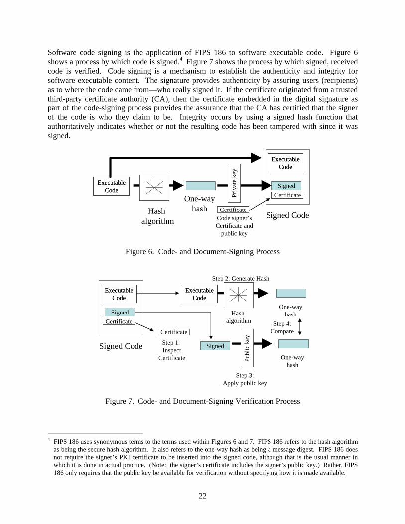
Software code signing is the application of FIPS 186 to software executable code. Figure 6 shows a process by which code is signed.4 Figure 7 shows the process by which signed, received code is verified. Code signing is a mechanism to establish the authenticity and integrity for software executable content. The signature provides authenticity by assuring users (recipients) as to where the code came from—who really signed it. If the certificate originated from a trusted third-party certificate authority (CA), then the certificate embedded in the digital signature as part of the code-signing process provides the assurance that the CA has certified that the signer of the code is who they claim to be. Integrity occurs by using a signed hash function that authoritatively indicates whether or not the resulting code has been tampered with since it was signed.
ExecutableCode
ExecutableCode
Hash algorithm
One-wayhash CertificateCertificate
Priv
ate
key
Priv
ate
key
ExecutableCode
ExecutableCode
SignedCertificateCertificate
Signed CodeCode signer’sCertificate and
public key
Figure 6. Code- and Document-Signing Process
ExecutableCode
ExecutableCode
SignedCertificateCertificate
Signed Code
ExecutableCode
ExecutableCode
CertificateCertificate
Step 1: Inspect
Certificate
Signed
Hash algorithm
One-wayhash
One-wayhash
Step 2: Generate Hash
Publ
ic k
eyPu
blic
key
Step 3:Apply public key
Step 4:Compare
Figure 7. Code- and Document-Signing Verification Process
4 FIPS 186 uses synonymous terms to the terms used within Figures 6 and 7. FIPS 186 refers to the hash algorithm
as being the secure hash algorithm. It also refers to the one-way hash as being a message digest. FIPS 186 does not require the signer’s PKI certificate to be inserted into the signed code, although that is the usual manner in which it is done in actual practice. (Note: the signer’s certificate includes the signer’s public key.) Rather, FIPS 186 only requires that the public key be available for verification without specifying how it is made available.
22

A document may also be signed and verified. In all cases, what is assured by code and document signing is the authorship, including the verification that third parties have not subsequently modified the code (or document). In no case does the user receive any assurance that the code itself is safe to run or actually does what it claims. Thus, the actual value of code signing remains a function of the reliability and integrity of the individual that signed that software and the processes that support software development and ongoing lifecycle support. Code signing, therefore, is solely a mechanism for a software creator to assert the authorship of the product and validate that others have not modified it. It does not provide the end user with any claim as to the code’s quality, intent, or safety. As mentioned in section 2.4, the integrity of higher-assurance entities (e.g., higher software levels) must not depend upon (human) administrative activity. Specifically, it must not be possible to misconfigure or mismanage high-assurance devices (including software) or systems. 3.2.2 Availability.
Availability issues directly impact the same three entities that were previously described for integrity: • Adequate availability (or spare capacity) is needed for the physical network media that
conveys data communications packets. Network availability can be attacked by causing the intermediate systems that forward packets to not function correctly, or else by saturating the network so that entities that need to use it cannot do so. The latter is called a DoS attack, which leverages the fact that network capacity is a finite resource. The first threat can be reduced by deploying intermediate systems that cannot be misconfigured (i.e., are high assurance). DoS exploits can be reduced by ensuring that the capacity of the network exceeds the cumulative network use, either by rate-limiting the devices that connect to the network or by implementing other QoS techniques.
• Availability of the security controls should be assured for a device that is used within a distributed system’s defense-in-depth security protections. This requirement can be met by ensuring that defense-in-depth and control life cycle principals mentioned in section 3.1 are followed. Key system resources should also either have redundancies or else have fail-safe protections.
• Availability should be assured for the applications that support airborne operations. These devices need to be designed to be impervious to bad data. They also need to be designed to withstand repeated and prolonged attempted accesses by rogue processes or systems (e.g., DoS attacks).
Availability is traditionally addressed by using either real-time systems where information flows are predetermined and systems are preconfigured to guarantee delivery of critical information, and/or by QoS network capabilities. For safety systems, this property should be included in the design. Mechanisms need to be in place to preferentially favor latency and jitter-sensitive communications over non-real-time flows, in accordance with the safety requirements that are articulated in section 5.2.
23

3.2.3 Authentication.
Authentication directly impacts the following entities: • Communications protocols should be configured with their security provisions turned on.
For example, routing protocols should be configured to use the appropriate password and hashed message authentication code for that deployment. The password needs to be unique for that system and protected via best current practices password protection mechanisms. Mutual authentication should be used whenever possible. This implies that human users and devices should both be assigned an appropriate identity by the authentication system used by the deployment (e.g., Kerberos, PKI; e.g., [57]). This, in turn, implies that the best common practice for that authentication system should be followed.
• Devices (both end system and intermediate system) and software with higher safety requirements should be designed so that they cannot be misconfigured, including their naming (if any) and IP addressing assignments, if possible. Devices and applications with more modest safety requirements need to ensure that their administrators are authenticated, and that administrative authorizations (including access control) are in accordance with the separation of duties with least privilege principals.
• Applications should ensure that their users (both processes and humans) are authenticated and, if applicable, their access control limited by separation of duties with least privilege. Authentication of human users should preferentially require two factored authentication (e.g., password plus PKI identity).
The ultimate goal of airborne security controls is to prevent safety failures. Physical techniques, along with policies and procedures, should be considered where practical. Remote access to safety-critical components should be minimized; however, where they are justified, authentication must be required. Authentication of airborne entities would be materially strengthened if the airborne authentication system were a constituent part of the same integrated authentication infrastructure serving both airborne and NAS systems. A number of candidate technologies could serve as the basis for such an authentication infrastructure. The requirements of such an infrastructure are that a common identity system needs to be created system-wide for the humans and devices that populate the total system. Those identities need to be authenticated by means of a common authentication infrastructure in accordance with best IA practices. The authentication system may or may not also be associated with authorization and/or access control. Well-known candidates for authentication systems include PKI (see RFC 3280, RFC 4210, RFC 3494); Kerberos (see RFC 4120); Remote Authentication Dial-In User Service (see RFC 2138, RFC 3580); and Authentication, Authorization, and Accounting (see RFC 3127, RFC 3539) including Diameter (see RFC 3588, RFC 4005). References 54 and 57 describe a PKI-based authentication system for the ATN. A choice of PKI to become an avionics authentication infrastructure correlates well with the extensive DoD PKI infrastructure that is currently being built by the DoD to support PKI within DoD systems.
24

3.2.4 Confidentiality.
Confidentiality is generally not relevant for safety. While there are some scenarios where passenger lists or the real-time location of an airplane might become known to an adversary and conceivably put the plane in jeopardy, this threat is not widely accepted within the FAA. The flight paths of commercial airplanes are already known, and the real-time information would have a short lifespan for an attacker. Old data is of little value to the attacker in the general case. 3.2.5 Nonrepudiation.
With regards to digital security, nonrepudiation means that it can be verified that the sender and the recipient were, in fact, the actual parties who sent or received the message, respectively. Nonrepudiation of origin proves that data has been sent, and nonrepudiation of delivery proves it has been received. Digital transactions are potentially subject to fraud, such as when computer systems are broken into or infected with Trojan horses or viruses. Participants can potentially claim such fraud to attempt to repudiate a transaction. To counteract this, the underlying processes need to be demonstrably sound so that such claims would not have credence. Logging of significant events is needed to create accountability. Log files should be protected from being modified or deleted. Nonrepudiation should be a required security attribute for all electronic parts distribution systems (e.g., software distribution). All electronic parts need to be signed in accordance with the U.S. Federal DSS [56] in accordance with an FAA-approved electronic distribution system. The source and integrity assurance of an electronic part is a critical element of verifying its authenticity prior to installation. This signature needs to be checked and verified at the deployment site before any electronic part can be deployed. The checks verify that the software has not been modified subsequent to being signed. The identity of the signer needs to be authenticated and authorized previous to deployment. In addition, whenever administrators (both device and human) interact with aviation equipment or administer devices within an aircraft, a log of their activity should be kept for analysis, accountability, and administrative purposes (e.g., fault investigation). The log file needs to record the specific identity of the human responsible, the time, actions performed, as well as optionally the location from which the access occurred. This log needs to be protected from subsequent modification or deletion. If network or host IDS are deployed, these log files should be available for those systems to read. 3.3 PARTITIONING NETWORK SYSTEMS.
Partitioning is an important mechanism by which the complexity of integrated systems can be reduced to improve the quality of the analysis and to mitigate failure conditions. For example, ARP 4754 says:
“System architectural features, such as redundancy, monitoring, or partitioning, may be used to eliminate or contain the degree to which an item contributes to a specific failure condition. System architecture may reduce the complexity of the
25

various items and their interfaces and thereby allow simplification or reduction of the necessary assurance activity. If architectural means are employed in a manner that permits a lower assurance level for an item within the architecture, substantiation of that architecture design should be carried out at the assurance level appropriate to the top-level hazard. … It should be noted that architectural dissimilarity impacts both integrity and availability. Since an increase in integrity may be associated with a reduction in availability, and vice-versa, the specific application should be analyzed from both perspectives to ensure its suitability. … Partitioning is a design technique for providing isolation to contain and/or isolate faults and to potentially reduce the effort necessary for the system verification process.” Quoted from section 5.4.1 and 5.4.1.1 located on pages 25 and 26 of ARP 4754 [6].
Partitioning provides isolation, independence, and protection for functions that are either highly critical (availability and integrity) or require protection (isolation, independence) to meet system availability and integrity requirements. VPNs create actual network partitions in full conformance to ARP 4754 section 5.4.1.1. VPN technologies appear to the network end-user to function as a private network, except that private network technology is not being used. VPNs are a well-established mechanism to partition network systems and to mitigate the types of risks previously mentioned in sections 2.1 and 2.2. According to RFC 4110, a VPN
“refers to a set of communicating sites, where (a) communication between sites outside of the set and sites inside the set is restricted, but (b) communication between sites in the VPN takes place over a network infrastructure that is also used by sites that are not in the VPN. The fact that the network infrastructure is shared by multiple VPNs (and possibly also by non-VPN traffic) is what distinguishes a VPN from a private network.” RFC 4110.
Figure 8 shows that VPN networks are created by means of distinct interface points established between the network entity that provide a shared network service provider functionality to the distributed customer sites that the service provider is supporting. This Handbook refers to the partitioned networks created by VPNs as being network enclaves.
26

Service Provider Customer SiteCustomer Site
InterfaceInterface
Figure 8. Interfaces Between Customer and Service Provider Networks
VPNs are examples of a multilevel network system that distinguishes between private customer networks, which are referred to as Red (or plain text) networks, and public service provider networks, which are referred to as Black (or cipher text) networks. Computers or devices within the service-provider network cannot access computers or devices within the customer’s networks, and vice-versa. It is called virtual because the service provider forwards the customer’s packets across its own network infrastructure in a manner that appears to the customer as if the service provider’s network were a link in the customer’s own private network. The service provider can transparently provide VPN services to multiple different customers over that same physical infrastructure with each VPN being securely partitioned from the other. Each customer is provided a high degree of confidentiality and integrity protections from the VPN service, which protect their users from other VPN users of the same physical network infrastructure. As described below, this protection can be accomplished either by data link layer protocol separations (i.e., Layer 2 VPN) or else by protocol tunneling (i.e., protocol stack encapsulations (i.e., Layer 3 VPN), which is the approach recommended by this study).5 These inherent confidentiality and integrity provisions can be further strengthened by using IPsec (see RFC 4301) in tunnel mode for Layer 3 VPNs, which is the VPN approach that this Handbook recommends. Figure 9 shows a Layer 3 VPN example. This specific example is of an Internet protocol version 4 (IPv4) network that is using IPsec in tunnel mode to create the VPN. Readers who are familiar
5 The mechanism by which network partitioning physically is accomplished differs in terms of the specific protocol
layer at which the partitioning controls occur. The approach recommended by this study does the partitioning at the network layer (Layer 3). The specific partitioning mechanism recommended by this study relies upon the controlled insertion (encapsulation) of a redundant IP packet header specific for the service provider network (i.e., the non-VPN enclave parts of the aircraft's network) within the protocol stack of the customer’s (i.e., network enclave) packets (see figure 9) while they are conveyed across the service provider’s network. This encapsulation occurs at the interface point shown in figures 8 and 10. The encapsulated packets are conveyed across the network service provider’s network by means of the encapsulated IP header (i.e., the service provider’s IP header which was inserted into the protocol stack). The original IP packet header of the customer’s packet, together with the entire contents of that original packet, is not visible to either the network service provider or to other VPNs supported by that service provider because they only can see the service provider-inserted IP header. Additional assurance is provided by the fact that IP addressing of the original IP header comes from the IP address space of the (customer) network enclave, while the IP addressing of the redundant (encapsulated) IP header comes from the service provider’s IP address space. The approach recommended by this study also has a third assurance mechanism: the customer’s entire original IP protocol stack is encrypted using FIPS-compliant encryption technology so that all network enclave packet information is in cipher text form while traversing the service provider’s network. These provisions ensure total separation between the various VPNs themselves as well as from the conveying service provider network.
27

with the DoD’s GIG network are encouraged to note that this figure could similarly be used to describe the GIG itself.
VPNEncapsulation
WorkstationWorkstation WorkstationWorkstation100.1.1.4
100.1.1.1
100.1.6.1
100.1.3.1
200.1.1.1
200.1.2.1 200.1.3.1
200.1.4.1
RIPHRIPP
Destination 100.1.6.1Source 100.1.1.4
RIPHRIPH
RIPP
Destination 200.1.4.1Source 200.1.1.1
RIPH RIPP
Destination 100.1.6.1Source 100.1.1.4
RIPH RIPP
Red IP Header (Red = inner IP layer = IP Layer used by the End Users) End user’s original data payloadIPsec ESP Header & TrailerBlack IP Header (Black = outer IP layer)
ESPBIPH RIPPRIPH ESPESPBIPH RIPPRIPH ESP ESPBIPH RIPPRIPH ESPESPBIPH RIPPRIPH ESPESPBIPH RIPPRIPH ESPESPBIPH RIPPRIPH ESP
Black Mobile Intranet 1“Service Provider” Network
Black IPBlack IP
BIPH
VPNEncapsulation
Black IPBlack IP
RIPH
RIPP
ESPBIPH RIPPRIPH ESPESPBIPH RIPPRIPH ESP
ESPBIPH RIPPRIPH ESPESPBIPH RIPPRIPH ESP
ESP
Figure 9. Example of VPN Encapsulation Using IPsec
The IETF has defined two distinct types of VPNs: • A Layer 2 VPN (L2VPN) provides a VPN logically occurring at the customer’s data link
layer by using the service provider’s physical network infrastructure operating at the data link layer. In L2VPN6, a network provider offers the customer access to a VPN via a data link layer service interface (see figure 8). Consequently, the VPN that is provided to the customer only appears to the customer to be a subnetwork (e.g., point-to-point wide area network link; multipoint LAN) within the customer’s own network. L2VPNs can be created by physically leveraging deployments of the service provider’s asynchronous transfer mode, frame relay, Ethernet encapsulation in IP, or multiprotocol label switching (MPLS; see RFC 2031) networks.
• A Layer 3 VPN (L3VPN) provides VPNs at the Network Layer (i.e., the IP layer). In L3VPNs7, a network provider offers the customer a private network infrastructure via an IP layer service interface (see figure 8). Consequently, the VPN that the service provider provides for the customer may be any IP topology hierarchy entity (e.g., subnetwork, area, AS, or network of networks; see section 7). L3VPN networks that are designed for heightened security use IPsec’s (see RFC 4301) encapsulating security payload (ESP) (see RFC 4305) in tunnel mode (e.g., see figure 9). This creates two IP layer entities—one used by the communicating private networks and a second encapsulation that is
6 see http://www.ietf.org/html.charters/l2vpn-charter.html 7 see http://www.ietf.org/html.charters/l3vpn-charter.html
28

exclusively used across the common service provider network. Other technologies, in addition to IPSec, can be used to create other types of L3VPNs. These include BGP/MPLS (see RFC 2547 and RFC 4364), Layer two tunneling protocol (see RFC 2661), IP/IP (see RFC 2003), and generic routing encapsulation (see RFC 2784).
L3VPN systems are so ubiquitous that special vocabulary has been developed to describe them. Packets traversing what figure 8 calls the customer site are either called Red or plain text packets, because they comprise normal, everyday IP stack transmissions. Communications within what figure 8 calls the service provider are either called Black or cipher text packets because the original packets have often been encrypted and encapsulated with a packet header of the conveying network. Note that because the Red (customer) packets are encapsulated into that conveying (service provider) Black network, the Black network itself is referred to as cipher text even though the native non-VPN communications within that (service provider) network are also normal plain text packets. Red packets have only one IP layer header and operate in the normal IP manner, but Black packets have two IP layer headers: the original IP layer header that was used by the end user (customer) and the encapsulated IP layer header that is used by the conveying (service provider) network. The selected VPN approach recommended by this Handbook is a L3VPN approach that uses IPsec in tunnel mode (reference 58 discusses several L3VPN approaches; the specific approach recommended by this Handbook is in reference 59). It was designed by the L3VPN working group of the IETF. This specific approach is described in section 5.3.1. Figure 10 shows a common L3VPN protocol stack example where two IP layer protocols exist: one for the virtual network (i.e., the underlying service provider network), and one for the customer’s own original packets. Because the service provider’s IP layer is an encapsulating redundant IP instance, it ensures that end systems within the two network systems cannot communicate together or be aware of each other (i.e., end systems have only one IP layer, not two). In this manner, the customer uses the service provider’s network without being aware of other traffic using that same network because the network traffic within the service provider’s network occurs at the encapsulating IP layer which the customer cannot see. It is similarly unable to access any devices that are directly attached to that network, nor can those devices access the customer’s network because they only support a single IP layer and cannot see an (encapsulated) two IP layer protocol stack. Computers in other VPNs using that same service provider’s physical network as well as hosts within the service provider’s network similarly cannot access or view entities in the customer’s network. L3VPNs are therefore an instance of multilevel network systems. RFC 4110, RFC 4111, and RFC 4176 provide architectural guidance for the creation of L3VPN network deployments.
29

Data Link Layer
Service Provider IP Layer
Customer’s IP Layer
Customer’s Transport Layer
Customer’s Application Layer
Interface
OriginalPrivate
CustomerNetwork Packet
EncapsulatedPacketHeader
fromServiceProvider
Figure 10. Customer’s L3VPN Protocol Stack as Seen Within the Network
Service Provider’s Network
3.4 EXTENDING POLICY INTO ARBITRARILY COMPLEX NETWORK SYSTEMS.
Different communities use different terms to refer to the same or similar concepts. For example, it was previously mentioned that current FAA safety assurance processes for airborne systems are based on ARP 4754, ARP 4761, and ACs (e.g., AC 25.1309-1A, AC 23.1309-1C); that software assurance is based on DO-178B; and that complex electronic hardware design assurance is based on DO-254. These references reflect common FAA parlance that speaks about the laws, orders, guidance, and processes that govern the civil aviation community by using those terms. However, in the parlance of the security community, laws, orders, guidance, and processes are referred to as being policy. Consequently, ARP 4754, ARP 4761, DO-178B, DO-252, and the ACs are referred to as being FAA safety policy. This point is mentioned because the following quotation is taken from the security community. It is important that the civil aviation community understand the intended meaning of this quotation (i.e., that differences in terminology do not cause misunderstanding). Therefore, using security community terminology, ARP 4574 and DO-178B reflect FAA policy for airborne software. Other entities (e.g., the DoD) have articulated other policy systems. Security models exist to provide a mathematical foundation by which well-defined policy systems (such as the DoD’s or the FAA’s) can be extended into arbitrarily complex and vast networked environments and still retain their original policy viability in a mathematically demonstrable manner. The goal of this section is to explain the technical foundation for this Handbook’s recommendation for how to extend the current civil aviation safety processes (e.g., ARP 4574 and DO-178B safety policy) into arbitrarily large networked system environments by means of the Biba Integrity Model.8
8 This statement consistently refers to security policy. This is because the context from which this statement was
taken was about security policy. The system (i.e., policy vis-à-vis security model) is not dependent upon whether the operative policy is a security or a safety policy. Rather, the operative concept is that it is a well-defined policy within the security domain. As previously stated, airborne safety is within the security domain whenever it pertains to networked environments.
30

“An important concept in the design and analysis of secure systems is the security model, because it incorporates the security policy that should be enforced in the system. A model is a symbolic representation of policy. It maps the desires of the policy makers into a set of rules that are to be followed by a computer system. … A security model maps the abstract goals of the policy to information system terms by specifying explicit data structures and the techniques necessary to enforce the security policy. A security model is usually represented in mathematics and analytical ideas, which is then mapped to system specifications, and then developed by programmers through programming code. … Formal security models, such as Bell-LaPadula are used to provide high assurance in security ... A security policy outlines goals with no idea of how they would be accomplished and a model is a framework that gives the policy form and solves security problems for particular situations.” [60, pages 239-240]
The Bell-LaPadula Confidentiality Model [61] was developed to formalize the U.S. DoD’s multilevel security policy. It forms the framework for confidentiality within the federal government’s information processing, including the DoD’s communications security (COMSEC) policy. This model creates a multilevel security policy system by means of mandatory access controls that label data at a specific classification level, and provide users clearances to a specific classification level. The controls ensure that users cannot read information classified at a security level higher than their own classification level nor write information to a lower classification level, except via the controlled intervention by a trusted subject (e.g., high-assurance guard (HAG)). The Bell-LaPadula Confidentiality Model framework is realized within military communications by creating networks, each operating at a specific classification level. These networks can operate as multiple single-levels of security (MSLS) systems9 or as DoD networks operating at system high, where the network is classified at the highest classification level of the data it conveys. For example, a DoD system-high secret network could transmit secret information as well as information classified below the secret level (e.g., sensitive but unclassified information and unclassified information) but not information at a higher classification level than secret. By contrast, all network entities in a MSLS network operate at the same specific security level. DoD networks operating at different classification levels are orthogonal to each other. For example, they are addressed, by definition, from address and naming spaces that pertain to their classification level. This results in network systems having distinct (i.e., unrelated) IP address and naming spaces rather than networks that operate at other classification levels in the general case.
“The Bell-LaPadula model is built on the state machine concept. This concept defines a set of allowable states (Ai) in a system. The transition from one state to another upon receipt of an input(s) (Xj) is defined by transition functions (fk).
9 Other possibilities (e.g., multiple levels of security and multiple independent levels of security) also exist.
However, the goal of this paragraph is to contrast MSLS with system-high because that contrast is relevant to subsequent airborne network policy issues.
31

The objective of this model is to ensure that the initial state is secure and that the transitions always result in a secure state.
The Bell-LaPadula model defines a secure state through three multilevel properties. The first two properties implement mandatory access control, and the third one permits discretionary access control. These properties are defined as follows:
1. The Simple Security Property (ss Property). States that reading of information by a subject at a lower sensitivity level from an object at a higher sensitivity level is not permitted (no read up).
2. The * (star) Security Property, also known as the confinement property. States that writing information by a subject at a higher level of sensitivity to an object at a lower level of sensitivity is not permitted (no write down).
3. The Discretionary Security Property. Uses an access matrix to specify discretionary access control.” [62, page 202]
The Bell-LaPadula Confidentiality Model, therefore, creates access control protections between entities at different sensitivity levels (e.g., DoD classification levels). A weakness of the Bell-LaPadula Confidentiality Model is that it only deals with confidentiality of classified material. It does not address integrity or availability—the key issues that underlie safety. The Biba Integrity Model, by contrast, is centrally concerned with integrity, a core safety issue in airborne network environments (see section 3.2.1). Figure 11 displays and contrasts how the Bell-LaPadula Confidentiality and Biba Integrity Models operate. It should be observed that the models operate as direct inverses of each other.
Biba Integrity ModelBell-LaPadula Confidentiality Model
High-Integrity Level High-Confidentiality Level
Medium-Integrity Level
Read OKproperty)
Write OK (* property)
(ss
Medium-Confidentiality Level
Write OK(* property)
Read OK ( ss property)
Low-Integrity Level Low-Confidentiality Level
Figure 11. Bell-LaPadula Confidentiality and Biba Integrity Models Compared
32

The Biba Integrity Model was created as an analog to the Bell-LaPadula Confidentiality Model to address integrity issues. Integrity comprises the following three goals (see page 204 of reference 62): • The data or system is protected from modification by unauthorized users or processes.
• The data or system is protected from unauthorized modification by authorized users or processes.
• The data or system is internally and externally consistent. For example, the data held in a database must balance internally and must accurately correspond to the external, real-world situation that it represents.
These integrity issues directly correspond to the safety policy concerns that DO-178B and ARP 4754 address. The Biba Integrity Model [24 and 25] is a direct analog to the Bell-LaPadula Confidentiality Model. The Biba Integrity Model shares the same concepts as the Bell-LaPadula Confidentiality Model, except that their mandatory policies are the inverse of each other (figure 11). The Biba Integrity Model is lattice-based and uses a lattice structure that represents a set of integrity classes and an ordered relationship among those classes (i.e., the DO-178B software level definitions; see section 2.2.2 of DO-178B). The simple Biba Integrity Model axiom (ss) requires that a subject at one level of integrity is not permitted to observe (read) an object at a lower level of integrity (no read down). The Biba * (star) Integrity Model axiom requires that an object at one level of integrity is not permitted to modify (write to) an object of a higher level of integrity (no write up), thereby preserving the higher level of integrity. As was the case with the Bell-LaPadula Confidentiality Model, a subject at one level of integrity cannot invoke a subject at a higher level of integrity. As was also the case with the Bell-LaPadula Confidentiality Model, the Biba Integrity Model has provisions for HAGs, which enable highly controlled functions to occur that would have otherwise been prohibited by the model. HAGs are trusted subjects that operate in a highly controlled and highly localized manner. However, in the Biba Integrity Model case, the HAG is concerned with integrity issues that permit a highly trusted integrity environment to safely receive communication from a less trusted one in a highly controlled way. For example, a HAG might be inserted into the network to support a Level C software system that needs to communicate with a Level A software system. This Handbook recommends using the Biba Integrity Model to extend current FAA processes into arbitrarily complex networked environments because • it is based upon integrity concepts that are directly relevant for extending DO-178B and
ARP 4574 processes into networked environments.
• it is a formal model on a par with the DoD’s Bell-LaPadula Confidentiality Model.
33

• it is a direct analog of the Bell-LaPadula Confidentiality Model and therefore creates synergies with existing DoD processes and certification environments.
However, other security models are also available, including other integrity models (e.g., the Clark-Wilson Integrity Model). Alternatively, the FAA could invent a security model of its own, including performing the necessary mathematical proofs. Any of these are valid alternatives for the FAA to consider. What isn’t a valid alternative is to attempt to extend ARP 4754 into networked environments without using a viable formal mathematical model (e.g., a security model) of some sort. Any such extension would necessarily be ad hoc and produce results that cannot be trusted to be safe. 4. EXTENDING THE CURRENT FAA CERTIFICATION ENVIRONMENT.
Current FAA safety assurance processes for airborne systems are based on ARP 4754, ARP 4761, and ACs (e.g., AC 25.1309-1A, AC 23.1309-1C). FAA software assurance is based on compliance with DO-178B, which guides software development processes. Complex electronic hardware design assurance is based on DO-254. The primary FAA certification standards are the respective regulations, FAA policy, and the ACs. This Handbook addresses how to extend these processes and certification environment to include networked airborne LANs in a mathematically viable manner. Because of the scope of the current FAA policies and processes, this Handbook addresses this larger task by explaining how to specifically extend the software assurance subset. Other aspects of FAA policy and processes can be extended in a parallel manner by leveraging a security model framework, the Biba Integrity Model. Figure 12 shows a simplified and abstracted view of the current FAA software assurance approval process. It shows that airborne software is currently developed and approved primarily according to the guidance and processes described within DO-178B.10 When individual software items are combined into integrated or complex systems, then additional safety considerations apply, which are documented in ARP 4754. These considerations address integration issues and system vulnerabilities that may arise from system dependencies. ARP 4754 refers to each element within that system as being an item. This same terminology is adopted by this Handbook.
10 There are other applicable policies and guidance in addition to DO-178B that can also be applied. Please recall
that this figure is a simplified abstraction.
34

1) Stand-alone software system:Focuses on that software entity ( DO-178B )
Stand - Alone Software System
2) Integrated or Complex Systems:Addresses each software Item ( DO-178B) as well as the potentially complex effects resulting from
). their integration together (ARP 4754
Complex Software
Complex Software
Complex Software
Arbitrarily Huge Number of Entities
Finite Number of Entities
LAN - Attached Software
LAN - Attached Software
LAN - Attached Software
LAN - AttachedSoftware
LAN - AttachedSoftware
Other connected LANs and Networks
Concerned with effective integration techniques
Concerned with fate sharing in a hostile environment
3) Networked Airborne LANs:A complex system in which every entity in the same network (i.e., the LAN and whatever the LAN directly or indirectly connects to) is inadvertently integrated together,regardless of the functional intent of the system design.
Processes must now also address possible network interactions during (and resulting from) network attacks.
Fate sharing: any compromised network entity can theoretically be used to attack other networked entities or their shared network environment .
Figure 12. Three Different Software Certification Environments
DO-178B builds upon system design concepts, such as the AC 25.1309-1A fail safe design concepts, one of which is integrity. Both DO-178B and ARP 4754 (i.e., section 2.2.2 of DO-178B, where it is called the “software level definitions,” and Table 3 of ARP 4754) rely upon the same five failure condition categories. Indeed, the same failure condition categories are consistently used within other civil aviation documents as well (e.g., Table 2-1 of DO-254 [12] or Table 1 of ARP 4761 [1]). Different processes are applied to items in the different failure condition categories so that items classified in the more severe safety failure conditions are developed by processes that produce higher assurance results. For software items, this is reflected in the DO-178B software level definitions. For this reason, this Handbook refers to DO-178B software levels as reflecting varying safety assurance levels. ARP 4754 is directly concerned with architectural considerations that pertain to highly integrated or complex airborne systems:
“System architectural features, such as redundancy, monitoring, or partitioning, may be used to eliminate or contain the degree to which an item contributes to a specific failure condition. System architecture may reduce the complexity of the various items and their interfaces and thereby allow simplification or reduction of the necessary assurance activity. If architectural means are employed in a manner that permits a lower assurance level for an item within the architecture, substantiation of that architecture design should be carried out at the assurance level appropriate to the top-level hazard. …
35

It should be noted that architectural dissimilarity impacts both integrity and availability. Since an increase in integrity may be associated with a reduction in availability, and vice-versa, the specific application should be analyzed from both perspectives to ensure its suitability.” [6, section 5.4.1, pages 25 and 26]
Because ARP 4754 addresses possible system vulnerabilities that derive from creating functional system relationships between items, to a certain degree, it can be characterized as being directly concerned with effective integration techniques between those system items. It assumes that the regulator can correctly identify the items that comprise a system as well as their mutual relationships. Aircraft network security is a systems issue. System development (ARP 4754), in conjunction with the system safety assessment process (ARP 4761), is responsible for defining network accesses, vulnerabilities, detection, and protection requirements. Some vulnerabilities will be mitigated by limiting and controlling access by using hardware and software capabilities. Some identified vulnerabilities will be mitigated by monitoring and detection capabilities. The security protection should be defined by the system and then by appropriate system requirements allocated to hardware, software and hybrids. This study assumes that best current IA practice will be followed including deployment of traditional IA security controls when appropriate. After implementation, these protections, mitigations and monitoring will also likely be verified and validated at the system level as well. Consequently, aircraft network security is an ARP 4754 issue. However, approving networked airborne systems in some ways represents a significant extension to ARP 4754. Networked systems differ from the ARP 4754 environment in several significant ways. Networked elements are systems that include all the networks and their constituent elements and users (including humans) to which the network is directly or indirectly attached. Networks are, therefore, arbitrarily large, and the many interrelationships of the system items are often too subtle to discern. Networks are inherently complex systems in which every item in the network is inadvertently integrated together, regardless of whether those items share any common functional goal. Approval of networked entities must now also address possible network interactions that occur during, and result from, networked attacks. The various networked elements potentially have a fate-sharing relationship with each other because any compromised network entity can, theoretically, be used to attack other networked items or their shared network environment. Therefore, networked airborne LAN environments are inherently “highly integrated or complex aircraft systems” with attributes that extend the complex relationships for which ARP 4754 was created: • In networked environments, ARP 4754 needs to be extended to consider each item within
the LAN to be integrated even if that item has no functional relationship with anything else. For example:
36

- If the LAN experiences a successful DoS attack, then each networked item in that LAN may potentially be unable to fulfill its function. Therefore, ARP 4754 must be extended in networked environments to ensure availability.
- If an item in the LAN becomes hostilely compromised by an attacker, then it potentially can be used by that attacker to attack the network itself or other items on the LAN. Therefore, ARP 4754 must be extended in networked environments to address LAN and item integrity. To ensure LAN and item integrity, ARP 4754 needs to be extended to require verifiably secure software installation procedures, as well as mechanisms to ensure the continued integrity of deployed items and systems.
• If airborne LANs are connected into networks, then the cumulative network system has similarly become integrated and existing safety processes need to become extended to each system and item within that larger networked system if they are to remain viable, even if any component elements within the larger system never itself becomes airborne.
• If the network has both device and human users, then ARP 4754 should also become extended to also pertain to humans. Every human or device with access to that network is a potential threat to that network and may potentially initiate attacks against the network itself, the LANs or subnetworks that comprise that network, or the items located within that network. If the network is directly or indirectly connected to the Internet, then there are, theoretically, more than one billion humans with potential access to that airborne LAN, despite the presence of intermediate firewalls. This means that mechanisms are needed within networked systems so that human behavior cannot deprecate historic DO-178B and ARP 4754 safety assurances.
This Handbook is also similarly concerned with extending DO-178B so that highly assured software items within networked environments can be developed and ensured to mitigate known network risks. The concept of highly assured software in networked environments explicitly means that the software can be trusted to behave in the same fashion before, during, and after attacks—something that current DO-178B processes cannot ensure because they do not explicitly address network attack threats. Consequently, current DO-178B software in networked environments may behave in an indeterminate manner during or after attacks if latent bugs within the software itself are successfully attacked by exploits that violate its integrity. Such software may become a potential threat to its deployment environment. It is potentially subject to misbehavior, corruption, or compromise, potentially including becoming used as a launching pad to attack other systems and items. A presupposition of this Handbook is that all airborne entities that are currently certified by DO-178B and/or ARP 4754 will need to become re-evaluated by the extended DO-178B and/or ARP 4754 processes before they could be deployed within network airborne environments. Unless these entities are re-evaluated using the extended processes, the safety provisions of the resulting system are indeterminate in networked environments.
37

4.1 EXTENDING ARP 4754 INTO NETWORKED ENVIRONMENTS.
There are two primary changes that are needed to extend ARP 4754 to address the challenges that occur within networked environments: • Existing ARP 4754 policies need to be provided the framework of a security model so
that the current policies could be extended in a mathematically viable manner into networked environments. This Handbook recommends that ARP 4754 become extended by leveraging the Biba Integrity Model.
• Strategic security controls need to be introduced into an extended ARP 4754 network deployment to provide IA protections that mitigate or reduce the efficacy of networked attacks. These IA controls should comply with best common IA practice, which is defined by the NSA’s IATF [49]. These controls should be implemented in accordance with defense-in-depth practices, which were discussed in section 3.1. Section 5.2 will apply best current SSE practices to the combination of current FAA safety policies and Biba Integrity Model concepts to define the requirements and relationships that underlie this study’s recommended exemplar airborne network architecture, which is presented in section 5.3. This network architecture includes a minimal subset of security controls that are needed to extend ARP 4754 policies into airborne networked environments.
These two primary changes create at least two secondary effects, which are also components of extending ARP 4754 into networked environments. The first of these secondary effects is the need to introduce viable software integrity life cycle protections as an ARP 4754 system requirement. There are two constituent aspects for creating software integrity: • The process by which software is loaded onto aircraft should occur within an FAA-
approved secure software download system. This system should ensure that only the correct versions of the correct software are loaded into aircraft. This implies that a reliable mechanism of creating software and software updates be defined to include a mechanism that securely stores software within an authoritative ground-based software storage facility. Assured software versioning mechanisms and processes need to be established that provide nonrepudiation assurances. A mechanism to associate software versions with appropriate target devices within aircraft also needs to be established. The software that is stored within the authoritative ground-based storage facility should be digitally signed in accordance with the U.S. Federal DSS (FIPS 186; see section 6.4) by an individual authorized to sign aircraft software. The secure software download system also should include provisions to ensure that mandatory onboard aircraft procedures verify that the received software has been signed by an authorized individual and that the software has not been modified subsequent to signing (i.e., software integrity and authorization protections) as a prerequisite for deploying the software within aircraft.
• Software, after it has been securely installed upon aircraft, should still undergo frequent (e.g., potentially several times an hour) integrity verification procedures to verify that the currently installed software is what it claims to be, and that it has not been clandestinely replaced by a Trojan horse or other unauthorized software variant. There are a number of
38

mechanisms by which such tests may be accomplished, including Tripwire mechanisms [63]. It is important that the onboard integrity verification procedures themselves be designed to be as impervious as possible to subversion from (hostile) network attacks.
The second secondary effect is to supplement the current ARP 4754 certification process by introducing a wide range of penetration tests upon the actual completed system. These tests should systematically address the capabilities of the network airborne deployment system under evaluation, including its security controls, to withstand the types of attack vectors that are described in references 39-45. These tests will, hopefully, identify many latent vulnerabilities within the proposed networked system itself that need to be fixed as a condition for approval. While such testing cannot provide assurance guarantees, it can identify specific areas needing additional attention.
“Operational system security testing should be integrated into an organization’s security program. The primary reason for testing an operational system is to identify potential vulnerabilities and repair them prior to going operational. The following types of testing are described: network mapping, vulnerability scanning, penetration testing, password cracking, log review, integrity and configuration checkers, malicious code detection, and modem security. … Attacks, countermeasures, and test tools tend to change rapidly and often dramatically. Current information should always be sought.” [14]
4.2 EXTENDING DO-178B INTO NETWORKED ENVIRONMENTS.
The system should identify the security and, thereby, the safety-related requirements for software. Software and system verification should ensure that they were correctly and completely implemented. The primary difference of extending software assurance processes into networked environments is to try to ensure that software vulnerabilities that can be attacked in networked environments do not exist. Latent bugs in software can be located in either the OS, the application, or both. Of the five respondents to the FAA LAN survey [1] who identified which OS hosted their airborne application, three did not use any OS at all, one used a COTS OS, and one used a high-assurance OS. While any latent software bug is a potential avenue of attack, not all software bugs have equal exploitative potential. The vulnerabilities that exist within applications that are not built upon an OS are a function of that specific application environment itself and the ability of the attacker to compromise or modify that environment. By contrast, root kits are available on the Internet for exploiting generic COTS OSs (e.g., Microsoft® Windows®, MacOS®, Unix®, etc.). These root kits often contain script-based attacks against the commonly known vulnerabilities of those systems with the goal to compromise the OS, deploy Trojan horses (for continued control), erase log files, and launch attacks on other entities. Section 2.3 discussed the dangers associated with using COTS OSs. For these reasons, COTS OSs should not be deployed within high-assurance environments except via a HAG. By contrast, high-assurance OSs are an excellent choice for high-assurance airborne network environments. If a high-assurance OS contains any vulnerabilities at all, those vulnerabilities are esoteric.
39

The DO-178B processes used to create software targeted for networked airborne deployments should be extended to explicitly reduce or eliminate the number of software vulnerabilities that can be leveraged by network-based attacks. However, as Ghosh, O’Connor, and McGraw have observed, these processes alone cannot guarantee the creation of high-quality software:
“Process maturity models and formally verified protocols play a necessary and important role in developing secure systems. It is important to note, however, that even the most rigorous processes can produce poor quality software. Likewise, even the most rigorously and formally analyzed protocol specification can be poorly implemented. In practice, market pressures tend to dominate the engineering and development of software, often at the expense of formal verification and even testing activities. … The result is a software product employed in security-critical applications … whose behavioral attributes in relationship to security are largely unknown.” [64]
Despite this, a variety of previous studies have proposed process extensions (e.g., references 13, 14, 16-18, and 64-66) using automated testing mechanisms at various stages of the development process to identify security vulnerabilities within software targeted for network environments.
This study concurs with those studies that development processes should be extended to include tests that examine the actual implemented product to verify that its development processes did indeed produce the expected results. Various specific mechanisms have been proposed to improve the current process have been proposed including:
• Use of model checkers on abstractions derived automatically from source code [13]
• Software fault injection into software to force anomalous program states during software execution and observing their corresponding effects on system security [64]
• Since a certain class of exploits relies upon buffer overflow vulnerabilities, various studies (e.g., reference 65) have also recommended specific development mechanisms and tools for reducing that vulnerability during software development. Each approach has a certain amount of overhead that may or may not be acceptable given specific implementation requirements. Regardless, these ideas, point out the desirability of understanding the root cause of the specific vulnerability and taking steps to correct it.
However, while these additional tests are potentially helpful, they cannot ensure that the resulting software is of a high quality. Tests only identify the presence of specific problems. Software testing alone cannot guarantee the absence of flaws that were not addressed by the test suite. Creating test suites to address all possible flaws that may exist in airborne software is an unachievable goal due to the myriad of different potential problems that could arise. There is no existing security theory or process that can extend testing systems to create guaranteed high-assurance results for networked environments. This is a significant certification issue. Fortunately, this problem can be partially mitigated by making rigorous code inspection become a constituent of the certification process for higher-assurance software (e.g., see DO-178B section 6.3.4 and Table A-5).
40

In conclusion, this Handbook recommends that the FAA study the viability of enhancing current DO-178B processes with the specific process extensions and tests suggested by previous studies (e.g., references 13, 14, 16-18, and 64-67). This study also recommends that the existing DO-178B assurance processes be very rigorously applied for higher-assurance software (i.e., Level A and Level B software) in networked environments. The approval process should include the following three specific tests: • A series of penetration tests should be performed upon the completed software item.
Specifically, the software (including its OS, if any) needs to be subjected to a range of network attacks described in vectors that are described in references 39-45. Any problems identified from these attacks should be fixed.
• The software under evaluation should be examined to verify that its internal construction complies with formal models of software construction such as being modular and layered in terms of a structured presentation within the implementation itself.
• A rigorous line-by-line code inspection of the software should be conducted to demonstrate a lack of bugs that can be hostilely attacked. This implies that the approver has an excellent understanding of how software bugs can be exploited by network attacks, and that the approver stringently examines that code base to identify and fix those problems.
This Handbook asserts that software items that do not undergo, or cannot pass, these three additional tests cannot be stated to be high assurance when deployed in network environments. Therefore, like any other non-high-assurance entity, they should only be deployed within high-assurance environments by means of an intervening HAG. 4.3 SIMILAR DoD AND FAA CERTIFICATION ENVIRONMENTS.
If the FAA were to extend existing safety processes by adopting the Biba Integrity Model for ensuring the safety of networked airborne and NAS systems, then the resulting IP network would look very much like the DoD’s GIG network infrastructure. This similarity is directly due to the Bell-LaPadula Confidentiality Model and the Biba Integrity Model being a direct analog of each other. The prime differences would be: • The FAA system is based upon civil aviation safety processes, and the DoD system is
based upon DoD confidentiality policies.
• The mandatory properties of the Biba Integrity Model are the direct inverse of the mandatory properties of the Bell-LaPadula Confidentiality Model (see figure 11).
The effects of the two models are directly parallel.
41

The FAA and civil aviation are concerned about airplane safety, and so they define airborne software in terms of the possible safety effects of software failure conditions. The federal government, which includes the DoD, is concerned about protection of sensitive information and programs. It defines its software systems in terms of the impact of that software upon the protection of sensitive information and programs. Although the focus on what is being protected against is entirely different between these two policy systems, the intent of the protection mechanisms are similar. Both enforce restrictions on how software operates within its system context. Both are also concerned with the impact of protection mechanisms and the consequences of possible failure effects. Both define their assurance system in terms of the worst-case effects of failure conditions. Coincidentally, both assurance systems are also remarkably similar to each other when viewed at a high level of abstraction, as show in table 1.
Table 1. Comparison of Safety Levels to Security Classifications
Safety (civil aviation) Security (DoD) Level A (catastrophic condition) Top Secret (exceptionally grave damage) Level B (hazardous/severe-major condition) Secret (serious damage) Level C (major condition) Confidential (damage) Level D (minor condition) Sensitive but Unclassified (could adversely affect) Level E (no-effect condition) Unclassified (no effect)
Therefore, although the civil aviation and federal government systems are distinct systems from each other and are oriented around very different issues, they, nevertheless, share important attributes. Additional similarities and differences between the two systems include the following: • Only the security side is concerned with confidentiality issues. This issue is briefly
discussed in section 3.2.4.
• Both safety and security are concerned with integrity issues. Once the programs and data are certified to be correct and operating correctly, any unauthorized changes could result in anomalous behavior. If a software item is evaluated to be at Level E, this unauthorized modification may only be a nuisance at worse. However, as analogous to highly sensitive federal government information, an unauthorized modification to a Level A- or B-rated software may have serious or disastrous results.
• Both safety and security are concerned with availability. If flight critical software on an aircraft is not available when needed, catastrophic results can occur. Likewise, if highly critical and time-sensitive information owned by the federal government is not available during mission planning may potentially result in loss of life.
• Both safety and security should be concerned with authentication and authorization. Without knowledge of who is attempting to access the software or data, modifications could be made by unauthorized personnel. If malicious, the unauthorized changes could potentially cause catastrophic results.
42

• Nonrepudiation is predominately in the security domain. From a security point of view, nonrepudiation provides the capability to ensure that any actions cannot be later denied (e.g., ensures the validity of audit information). It provides a basis for process integrity and accountability.
Both models partition networked items into distinct network systems that operate at a specific assurance level. In the civil aviation system, this level is proposed to be in accordance with DO-178B and ARP 4754 policy. In the DoD system, it is in regard to confidentiality levels articulated by Federal Law. Regardless, distinct networked systems operating at known classification levels are created. • DO-178B systems using the Biba Integrity Model can also be deployed in terms of
system-high network groupings, just like DoD systems can. However, it differs from DoD systems in that the system high for the Biba Integrity Model is in terms of the lowest integrity classification for that common grouping (i.e., it is actually a system low, since the mandatory policies of the Biba Integrity Model are the inverse of the Bell-LaPadula Confidentiality Model).
• DO-178B systems using the Biba Integrity Model can also be partitioned into MSLS systems, each operating at a specific safety classification only, in a parallel fashion to DoD systems.
• Network partitioning in terms of the Biba Integrity Model is recommended to occur by means of civilian VPN technologies, though the military COMSEC equipment equivalents could be used. Specifically, this study recommends that Biba Integrity Model partitioning is accomplished by IPsec’s encapsulating security payload (ESP) in tunnel mode (see RFC 4301, which defines IPsec, and RFC 4303, which defines the ESP protocol).
Section 5.4.1.1 of ARP 4754 discusses mechanisms to partition highly integrated or complex aircraft systems. Both the Bell-LaPadula Confidentiality and the Biba Integrity Models explicitly rely upon similar partitioning techniques. In IP environments, VPNs permit the creation of a networked system that operates at a specific assurance level within a larger cumulative network environment that operates at many different assurance levels. VPNs specifically enable associated partitioned networked items to operate at a trusted specific assurance level that potentially operates at a different assurance level than the underlying physical network itself (e.g., the LAN) or other VPNs (and their networked items), which are also similarly supported by that same physical network. DoD COMSEC is currently also based upon IPsec’s ESP in Tunnel mode. When DO-178B and ARP 4754 safety policies are organized according to the Biba Integrity Model, these same DoD COMSEC and industry VPN concepts can be applied to airborne and NAS safety deployments. Figure 13 shows those same concepts applied to DO-178B software level definitions using the Biba Integrity Model. Specifically, this figure shows the Biba Integrity Model elements applied as MSLS networks. Figure 13 shows devices operating at safety classification X (e.g., either Level A, B, C, D, or E). These devices operate within a network (e.g., a VPN) functioning at
43

that specific safety classification level. Network partitioning in terms of safety classifications may implicitly involve data categorization to the extent that data is directly related to safety distinctions. Figure 13 shows that those networks operating at the same safety level may be discontinuous. For example, the items located at the top left need to communicate with the items located at the top right, and vice-versa. The top-left items can be within the NAS and the top right within an airplane. These discontinuous network segments are connected by a different network system operating at a different safety level (i.e., DO-178B software level definition) through encrypting the original packets and encapsulating them into the protocol headers of the lower network system (see section 5.3.1). The top networks in figure 13 are the customer site networks mentioned in figure 8. It is a Red (plain text) network. The bottom (linking) network is the service provider network mentioned in figure 8. It is a Black (cipher text) network, though it almost certainly also conveys plain text packets that are operational at its own classification level. The encapsulation and encryption is performed in accordance with IPsec’s ESP in tunnel mode, which is the Encapsulates & Encrypts function shown within figure 13. That function is also the interface described in figure 8. The stack chart of the packets from the top network system (operating at safety Level X) appears as shown in figure 10 when they are conveyed over the bottom network system of figure 13 (operating at safety Level Y). This approach corresponds to both the current DoD GIG and industry VPNs.
Network operating ata Safety Level different
than X (i.e., Y)
Device at Safety Level Y
Device at Safety Level Y
Encapsulates & Encrypts
Encapsulates& Encrypts
Networks operating at
Safety Level X
Device at Safety Level X
Device at Safety Level X
Device at Safety Level X
Device at Safety Level X
Device at Safety Level Y
Figure 13. DO-178B Classifications Using Biba Integrity Model
VPN encryption should use FIPS compliant encryption algorithms. Protocol encapsulation ensures that these are logically distinct network systems that are unable to address or interwork with different logical network systems operating at different safety levels except at the encapsulation and encryption interface (see section 3.3). This is true regardless of whether or not these networks have physically distinct media systems. Specifically, figure 13 can be interpreted as showing interconnected networks having three distinct physical media instances (top left, top right, bottom) with the top two physical media systems operating at the same safety level that is a different safety level than the bottom network system. However, figure 13 can also be interpreted as showing a network that has the same ubiquitous physical media subdivided into logically different network elements. In the latter case, the top left, top right, and bottom all use the same physical media. In this case, different logical network systems, each having effective
44

network security and isolation through protocol encapsulation, have been created from the same physical system. VPN techniques enable the creation of partitioned network systems even when they are sharing a common physical network. 4.4 RELATING SAFETY CLASSIFICATION LEVELS TO THE COMMON CRITERIA.
The exemplar airborne network architecture described in section 5.3 relies upon security controls (e.g., firewall, packet filter, autonomous system boundary router (ASBR), VPN encapsulation gateways, HAGs) to provide security protections for the networked system so that the resulting system can be assured to operate at a specific safety level. As explained in section 4.1, airborne networks need to operate at specific safety levels as defined by FAA policy (e.g., DO-178B, ARP 4574) and enforced by the Biba Integrity Model. Therefore, for certification purposes, the integrity of these security controls must be mapped to the appropriate DO-178B safety level. This implies that these security controls can be evaluated in terms of specific DO-178B safety level assurances for the Biba Integrity Model provisions to be viable. This section discusses this issue. The FAA has sponsored a growing body of work evaluating common security and safety processes and systems [14-16 and [19]. This issue directly impacts aircraft that need to be dual certified by both the FAA (for safety) and DoD (e.g., the United States Air Force; for security). However, this issue is also of a more generic interest. For example, the DoD, in addition to defining their information systems in accordance with confidentiality (security) constructs, is also concerned with safety issues, which are defined in terms of MIL-STD 882D [68]. MIL-STD 882D shares many similarities with existing civil aviation concepts including a similar five-level safety classification system. Although safety and security are very distinct concepts, they share some common attributes that permit them to be compared in several different ways. For example, the FAA and the DoD have created comparable certification environments that have similar concepts of assurance. Both safety and security also have similar integrity attributes that may be leveraged in a Biba Integrity Model environment to provide a mechanism that relates otherwise dissimilar safety and security concepts. Both approaches will be considered in this section. Department of Defense Instruction (DoDI) 8500.2 Enclosure 4 [69] provides specific guidance to DoD systems on how to identify specific CC (security) protection profiles. While there are many details associated with this process, the issues examined in DoDI 8500.2 Enclosure 4 are particularly relevant for FAA consideration. This is because while the DoD is primarily oriented to confidentiality issues, which have little or no safety consequence, Enclosure 4 focuses on availability and integrity, which are the security attributes that are most relevant to airborne safety in networked environments (see sections 3.2.1 and 3.2.2). For example, “the FAA often considers data integrity and availability among the most important” security services [52, page 1]. The following are direct quotations from DoDI 8500.2 Enclosure 4:
“The IA Controls provided in Enclosure 4 of this Instruction are distinguished from Common Criteria security functional requirements in that they apply to the definition, configuration, operation, interconnection, and disposal of DoD
45

information systems. They form a management framework for the allocation, monitoring, and regulation of IA resources that is consistent with Federal guidance provided in OMB A-130 [see [70]]. In contrast, Common Criteria security functional requirements apply only to IA & IA-enabled [information technology] IT products that are incorporated into DoD information systems. They form an engineering language and method for specifying the security features of individual IT products, and for evaluating the security features of those products in a common way that can be accepted by all.” [69, E3.4.3] “This enclosure [i.e., Enclosure 4 within DoDI 8500.2 [69]] establishes a baseline level of information assurance for all DoD information systems through the assignment of specific IA Controls to each system. Assignment is made according to mission assurance category and confidentiality level. Mission assurance category (MAC) I systems require high integrity and high availability, MAC II systems require high integrity and medium availability, and MAC III systems require basic integrity and availability. Confidentiality levels are determined by whether the system processes classified, sensitive, or public information. Mission assurance categories and confidentiality levels are independent, that is a MAC I system may process public information and a MAC III system may process classified information. The nine combinations of mission assurance category and confidentiality level establish nine baseline IA levels that may coexist within the GIG. See Table E4.T2. These baseline levels are achieved by applying the specified set of IA Controls in a comprehensive IA program that includes acquisition, proper security engineering, connection management, and IA administration as described in enclosure 3 of this Instruction.” [69, E4.1.1]
The DoDI 8500.2 Enclosure 4 MAC is defined by the intersection of integrity and availability (the MAC level) and DoD security classifications (the confidentiality attribute for each MAC level). This pairing potentially provides a framework for considering FAA and the CC processes and concepts in an integrated manner. Specifically, it is conceivable that the modest FAA confidentiality requirements (if any) roughly equate to the DoD public (i.e., basic) confidentiality level, such that the DO-178B software levels can be mapped into the public variant of the three different MAC levels to identify IA (i.e., security) requirements for FAA systems. Of course, since DoDI 8500.2 is a DoD document, this association is in terms of DoD processes, and not FAA processes. However, it does provide a possible intersection that may be relevant for increased synergy between the DoD and FAA. Therefore, DoDI 8500.2 may provide a starting point for potentially integrating airborne network safety and security concepts into a common federal system by leveraging established DoD processes that comply with federal law. Nevertheless, to pursue this, the FAA needs to study and verify whether the three MAC levels identified by DoDI 8500.2 provide adequate granularity for the NAS and airborne system requirements. If they do, then the FAA could directly leverage current DoD processes, if appropriate, perhaps creating an integrated safety and security engineering system U.S. government-wide.
46

This Handbook recommends that this issue needs further study to become useful. Consequently, at this time, it does not provide the assurances needed to underlie our exemplar airborne network architecture. Therefore, this Handbook will tentatively relate safety and security issues in terms of the relative assurances provided by their respective certification processes. The CC has provided seven predefined security assurance packages, on a rising scale of assurance levels, which are known as Evaluation Assurance Levels (EALs). EALs provide groupings of assurance components that are intended to be generally applicable. The seven EALs are as follows: • EAL 1 – Functionally Tested • EAL 2 – Structurally Tested • EAL 3 – Methodically Tested and Checked • EAL 4 – Methodically Designed, Tested, and Reviewed • EAL 5 – Semiformally Designed and Tested • EAL 6 – Semiformally Verified Design and Tested • EAL 7 – Formally Verified Design and Tested EAL 1 is the entry level classification of the system. EAL 1 through EAL 4 (inclusive) are expected to be generic commercial products. EAL 5 through EAL 7 (inclusive) are considered to be high-assurance products. Carol Taylor, Jim Alves-Foss, and Bob Rinker of the University of Idaho have studied the issue of dual software certification [71] for CC and DO-178B. Figure 14 is copied from this study and shows a gap analysis between the CC classes and the DO-178B processes. This study provided a fairly detailed analysis of the differences. It suggested that security functionality certified at CC EAL5 can be directly compared with DO-178B Level A.
47

Software Quality Assurance<no correspondence> <no correspondence>AVA—Vulnerability AssessmentVerification ProcessATE—Tests Software Software Planning Process ALC—Life Cycle Support <no correspondence>AGD—Guidance DocumentsSoftware Development Process ADV—Development Software<no correspondence>ADO—Deliver and OperationSoftware Configuration ManagementACM—Configuration Management
DO-178B Processes Common Criteria Classes
Figure 14. Gap Analysis in the Alves-Foss, et al. Study [71]
This Handbook recommends that the basis for equivalency between the integrity of security controls and DO-178B safety levels should be confirmed by further study. However, in the interim, the FAA can leverage the University of Idaho results to temporarily equate the assurance of security systems certified at the CC’s EAL5 with airborne software certified at DO-178B Level A. This means that security controls deployed on aircraft that support DO-178B Level A software currently should be certified at CC EAL5 or higher. 5. EXEMPLAR AIRBORNE NETWORK ARCHITECTURE.
This Handbook’s examplar safety and security network solution, presented in section 5.3, naturally follows from the material that has been presented thus far. The final remaining explanatory concept, which is needed to create the exemplar architecture itself, is to discuss best SSE practice. Section 5.1 presents this remaining explanatory topic. Section 5.2 then applies the SSE practices to the combination of current FAA safety policies and Biba Integrity Model concepts to address the network risks (see section 2). This application defines the requirements and relationships that underlie this study’s recommended exemplar airborne network architecture. Section 5.3 presents the resulting airborne network architecture that directly derives from these requirements and relationships. That architecture defines an exemplar environment needed for airborne network safety that implements FAA policies extended into network environments by the Biba Integrity Model. That section also includes the recommended configurations of the security controls in order to achieve a minimal set of defense in depth protections. A given deployment may choose to implement additional controls (in addition to those described in section 5.3) to address specific requirements of that deployment. 5.1 SYSTEM SECURITY ENGINEERING METHODOLOGY.
System Security Engineering (SSE) defines the process for integrating computer security concepts and technologies into coherent system architectures (see figure 15). To achieve maximum benefit from the SSE process, it should permeate the entire life cycle of a system. The SSE process helps to ensure that all decisions are consistent with the overall system design and purposes. This process also avoids the bolted-on phenomenon that has proven over time to be
48

ineffective. Only by being developed as an integral part of the systems in which they operate can subsystem elements successfully counter serious threats and reduce vulnerabilities.
System SecuritySpecificationDevelopment
Threats / Hazards
Ops Environment
Technology
AdversaryAnalysis
BaselineDesign
Concept
Entry intoDevelopment
FAA safetyrequirements
SecurityWorking
Group
LessonsLearned
VulnerabilityAnalysis
DesignConcepts
IASecurityCriteria
CriteriaAnalysis
Trade-OffStudies
SecuritySpecificationRequirements
Countermeasures
SecuritySpecificationDevelopment
FAA Safety Requirements
Figure 15. Security Engineering Process Security is the result of a complex interaction between multiple elements. As a result, one critical component of the SSE process is to understand the operational environment. This is accomplished by examining the actual operational environment to identify high-value assets, determining the threats to those assets, understanding their vulnerabilities, and selecting the proper countermeasures to protect the high-value asset. This process also provides an accrediting officer with the information needed to determine whether the residual risk is acceptable. The Systems and Software Consortium11 has developed well-accepted SSE processes. Their generic approach can be summarized by the following steps. 1. Determine the security policies. This is a high-level definition of what is allowed and
what is forbidden within the system. The policies provide the basis for determining the security requirements that will be developed and implemented. Without good security policies, one cannot determine the high-value assets and data that must be protected.
2. Determine and specify the security requirements. In this step, requirements for the protection of assets and data are determined using the security policies as a guide. It is essential that only requirements be specified, not solutions nor constraints. Therefore, the requirements must be stated in technology neutral terms. In addition, the requirements must be practical and testable to permit eventual verification that the requirements have been satisfied by the final system. Finally, the security requirements should not be open to interpretation. This is accomplished in high-assurance systems by
11 See http://www.software.org
49

specifying the security design via mathematical formalisms. However, this is rare. In most cases, English is used to specify the requirements. Care must be taken to avoid ambiguity of meaning.
3. Establish a security engineering plan. This plan should include items critical to the design and implementation of the security protection mechanisms. Such items include the security requirements, constraints, and decisions already made. It should be used to help allocate the resources needed to properly complete the project while simultaneously establishing realistic expectations.
4. Learn from past mistakes. Poor development practices typically result in security vulnerabilities. By examining these past development practices and identifying those that improve or hinder system security, valuable lessons can be obtained and future implementations improved.
5. Document the operational environment. This is typically done in a document called the Concept of Operations (CONOPS). It describes the environment in which the system will operate, the roles and responsibilities of the major players, how the system is designed to normally operate, and potential contingency modes of operation. The security environment can be included in the CONOPS as a separate section or included in its own document (a Security CONOPS). Elements of this Security CONOPS should include a reiteration of the security requirements, the process used to select all countermeasures, how defense-in-depth is implemented, how the security mechanisms will operate including user impacts, the effectiveness of the implemented countermeasures, how misuse is prevented or detected, the response mechanisms to a misuse incident, and the recovery process, if needed.
6. Perform a risk analysis. The risk analysis examines the operational environment to determine high-value assets, the threats to these assets, their vulnerabilities, countermeasures needed to reduce the risk for each threat/vulnerability pairing, and a validation of the cost effectiveness of each countermeasure. For airborne environments, this approach differs from the traditional security engineering process by including safety as a key factor. It also differs from traditional safety analysis by considering the possible effects of malicious actions. In a little more detail, the first step should determine the high-value assets to assist in focusing where the limited security dollars should be spent. In placing a value on each asset, the cost effectiveness of the selected countermeasures can later be determined. Once the assets are determined, each threat, which is asset- and environment-dependent, must be ascertained. In conjunction with this, the vulnerabilities of these assets must also be determined. Once the threats and vulnerabilities are determined, each threat is matched with the appropriate vulnerability. Any vulnerability without a threat or vice versa can be ignored. Otherwise, countermeasures are selected to reduce the threat and the cost of the countermeasures determined. A tradeoff is then performed between threat and vulnerability matches, countermeasure costs, and protected asset value.
7. Design the security architecture using the above information. The risk analysis above will identify the areas requiring protection and the cost effective countermeasures
50

requiring implementation. The security design should be consistent with accepted best practices. One such best practice is the concept of defense-in-depth (discussed in section 3.5). This concept uses the medieval castle as its model. Multiple layers of defense are implemented so that when one layer is successfully penetrated, other layers of protection still exist. While it is widely accepted that no security mechanism is foolproof, an architecture implementing the defense-in-depth concept should sufficiently delay the attacker to allow for the detection of the attack and to implement an appropriate response. This assumes that full control lifecycles have been implemented to enable attack detection and response. Other best practices include least privilege, object reuse, separation of roles, need-to-know, secure failure and recovery, input validation, and training plans.
8. Develop the system. In this step, the design is fleshed-out and technologies are selected for implementation. In most cases, this includes the use of COTS systems and applications software. However, COTS products with a large installed base are attractive targets for attackers. As a result, all COTS products should be identified and their suitability for implementation within specific NAS or airborne subsystems determined during risk analysis. Another potential security concern is the outsourcing of software development. The problem that must be considered is the potential for the introduction of malicious software into the developed and delivered product. Steps such as security vetting of the development company, verifying the company’s development practices (capability maturity models or International Organization for Standardization certified), and issues, such as ownership, should be considered. Next, the developed system should include auditing capabilities and, optionally, automated alerts to administrative personnel. Only by examining the audits, can misuse actions be traced to the offending user or program. As a result, these audits should be organized by individual users, and all user or software interaction with protected data should be recorded. Other elements of concern during the development process include the software languages used (some are inherently insecure), constructs used, how errors are handled, the use of cryptography and digital signatures and their implementation, the access control mechanisms selected and implemented, and the proper implementation of all countermeasures.
9. Test the developed system. In this step, the implemented security countermeasures are verified. Testing can be as simple as a visual verification or as complex as a full mathematical proof of correctness. Most testing falls in between the two, relying upon use and misuse cases to verify correctness. These cases ensure the system properly protects the high-value assets from malicious insiders and outsiders. The approach taken is typically documented in a test plan that includes the use and misuse cases. The result of the testing phase is a report of the tests performed and the verification that all security functionality has been exercised according to the plan.
10. Operations. Such issues still relevant to the security systems engineering process include processes for software updates. During the operation of the system, security mechanisms must be patched and updated. This process should be planned prior to operations.
51

5.2 APPLYING THE SSE METHODOLOGIES TO AIRBORNE NETWORKS.
Complying with the SSE process is intended to produce a best current practice security design for a specific deployment in terms of the specific requirements and needs of that deployment. SSE was not devised to create generic security designs for generic deployments. This Handbook leverages SSE to benefit from best current practices rather than to invent a novel approach with unproven results. This application of SSE solely addresses the articulation of current FAA safety policy (e.g., DO-178B and ARP 4754) in terms of the Biba Integrity Model framework. It does not address the very important issues and requirements that specific deployments have that extend beyond this foundational policy framework. For this reason, this Handbook views its resulting exemplar airborne network architecture (see section 5.3) only to be a minimal airborne network architectural subset, which needs to be built upon to satisfy the actual safety and security requirements of specific NAS and airborne deployments. The initial steps of the SSE process will be examined in this section to examine the safety requirements of a generic networked airborne system environment. As previously observed, networked environments have both safety and security requirements. Although the SSE processes were originally intended to address security needs only, this section applies them to existing FAA (i.e., DO-178B and ARP 4754) safety policies applied within a Biba Integrity Model context. As explained in section 4.1, this policy foundation also leverages best current IA practices as articulated by the IATF, most notably its defense-in-depth (see section 3.1) provisions. Regardless, the first step in the SSE process is to determine the policies that underlie a deployment. Our policies are the current DO-178B and ARP 4754 safety processes mapped in terms of the Biba Integrity Model framework. The second step in the SSE process is to determine the security requirements that are derived from the security policies. Because this Handbook uses existing FAA safety policy mapped to the Biba Integrity Model framework (i.e., step 1 of the SSE process), the result of this step produces the following set of safety requirements: • Requirement 1: Networked entities that are classified at a software level that has
potential safety repercussions to aircraft operation (i.e., Level A, Level B, Level C, or Level D) shall be partitioned from the larger network environment and combined into a network enclave that functions at that specific software safety level with other entities classified at the same safety level (see figures 13 and 16). Networks or items at a different safety level from each other shall not be able to communicate together (see Requirements 6 and 8 for two specific exceptions to this general requirement). For example, Level B systems or software shall not be combined into the same partitioned network enclave with Level C systems or software.
• Requirement 2: Because Level E software systems have no safety repercussions to the aircraft, they do not need be partitioned (i.e., formed into common network enclaves). Note that the FAA may want to study whether Level D software should be treated as a Requirement 1 or a Requirement 2 entity. Because this Handbook did not know the most
52

appropriate way to treat Level D entities, it is tentatively classifying them as Requirement 1 systems.
• Requirement 3: Physical network media and devices that operate at the physical or data link layer of the OSI Reference Model (i.e., data link layer and below), deployed within aircraft, shall be assured at the same software (safety) level as the highest software level entity that they support. For example, if entities operating at Software Level A are conveyed within a physical airborne network, then the media, switches, and/or bridges that create that physical network system that transport Level A packets shall also be assured at Software Level A.
• Requirement 4: Entities that are located outside of aircraft, such as ground-based, space-based (e.g., satellite), and other aircraft that directly or indirectly communicate with elements within the airborne system at Level A through Level D (i.e., Requirement 1 systems) shall belong to the same distributed network enclave partition as the airborne software or system with which they are communicating (see figures 13 and 16). These entities, therefore, need to either have been certified and accredited at that software level or else be connected to that software level (VPN) network via a Biba Integrity Model HAG (see Requirement 8).
• Requirement 5: The physical network system elements that connect the airborne network elements with other entities located outside of that aircraft (see Requirement 4), need to comply with the same requirements that pertain to aircraft physical network systems (i.e., Requirement 3).
• Requirement 6: If a software system (e.g., a combination of software entities) primarily or exclusively communicates in a tight relationship within their select group and the group is comprised of entities at different software levels, then that tight-knit, cross-level community can be combined into a partitioned network enclave together (e.g., integrated modular avionics systems). That localized enclave operates in a system-high manner. There needs to be a special extenuating process or policy established within that enclave to enable a system-high situation to exist, since it represents an exception to the most direct application of the Biba Integrity Model, which naturally results in MSLS partitioned networks (i.e., see Requirement 1). System-high networks are classified at the software level of the lowest classification level entity within that grouping and are distinct network enclave partitions from MSLS partitioned enclaves (i.e., Requirement 1 systems).
• Requirement 7: It needs to be noted within the assurance process whenever a system or software entity has safety-related network connectivity requirements or dependencies with any other system or software entities. Specifically, it should be noted if entities have real-time, latency-sensitive, or high-availability connectivity requirements with specific other entities. If the partitioned network enclave that supports those entities cannot be assured to satisfy those network connectivity requirements, then those elements shall be supported via a dedicated databus (or LAN) that solely exists to meet that
53

connectivity requirement.12 If a dedicated physical databus needs to communicate with other LANs or databuses, then the dedicated physical databus or LAN is linked to that other physical network via a router (i.e., a relay device operating at the network (i.e., IP) layer only).
• Requirement 8: Biba Integrity Model HAGs may be strategically positioned, on an as-needed-only basis, to safely join together entities classified at different software levels. The HAG is specifically designed to address the issues that otherwise would hinder a less trusted integrity entity to safely communicate with a more highly trusted one in accordance with Biba Integrity Model precepts. The HAG device is a middlebox that is inserted between the communicating entities or networks to provide the controls (e.g., availability and integrity) necessary to ensure safety between the communicating entities. The HAG is a highly trusted device. It therefore needs to be certified at both the highest software level of the specific entities it is connecting (for safety) and also at EAL5 or above (for security).
It is clear that these requirements require a system or software entity to be classified at a specific software level and to communicate only with entities classified at that same level via a VPN network, also certified at that same level in the general case. The third step in the SSE process is to determine a security engineering plan. The security engineering plan used for networked airborne systems shall comply with the extended DO-178B and ARP 4754 concepts explained in sections 4.1 and 4.2. Steps 4 and 5 of the SSE process are specific to a given deployment. These steps need to be followed to extend the generic architecture identified by this study into a specific deployment environment. In step 6, a risk analysis for that deployment is performed. The result of a risk analysis for generic networked airborne environments was previously presented in section 3.2. With the previous steps as background, the SSE process in step 7 then creates a security architecture. This security architecture applies best current IA practice (i.e., IATF) to the resulting generic system. The resulting security architecture for a generic airborne network environment is presented in section 5.3. 5.3 EXEMPLAR AIRBORNE NETWORK ARCHITECTURE.
Figure 16 shows a high-level view of a generic network design that this Handbook recommends for airborne networked environments. This design was constructed by following the SSE processes (see section 5.2) for the extended DO-1789B and ARP 4754 processes described in sections 4.1 and 4.2. Specifically, this section provides the generic security architecture defined by SSE step 7.
12 The reason for the dedicated databus (or LAN) is to ensure that the special network requirements of those devices
will be met. It is, of course, preferable if their requirements can be met in the normal manner (e.g., via a common high-assurance LAN). However, this requirement exists to say that it is OK to provide special databus connectivity for certain devices having requirements that absolutely require dedicated physical databuses or LANs.
54

SW = Software
Figure 16. Secure Generic Airborne Network Design (High-Level View)
Figure 17 shows how the recommended architecture addresses many of the network risks that were discussed in section 2.
SW = Software
Figure 17. How Design Addresses Network Risks
Virtual Private Network
Virtual Private Network
Aircraft Control
Level A SWLevel A SW
Level B SWLevel B SW
Level D SWLevel D SW
Firewall Packet Filter
Passenger Network
High-Assurance LAN
PassengerN
Virtual Private Network
Passenger2
Passenger1
Level C SWLevel C SW
High-Assurance LAN
Encapsulation System
Virtual Private Network
Virtual Private Network
Virtual Private Network
Route
Separate LAN forpassengers so they can bypass the packet filter.
QoS and network assurance that passengers cannot
conduct DoS in the address, access or
aircraft control LAN.
Securely limits threat environment: Controls population that can access this network to that VPN population only. Other VPNs have different address and name spaces. Each VPN securely partitions the network.
VPNs and their items are difficult to attack except by inserting a “man in the middle,” including compromising the encapsulation gateways. encapsulating gateway policy together with the firewall and packet filter policies help protect VPNs from being vulnerable to attack. Provides airplane network perimeter defense.
Configured so that onlynetwork management orIDS devices can sendpackets having the router asthe IP destination address.
Ideally, needs virtual linkcapability to provide physical layer connectivitythat duplicates the VPNconnectivity limitationsfor defense in depth protection.
Aircraft Control
Level A SWLevel A SW
Level B SWLevel B SW
Other Air or Ground Entity
Level A SW
Level B SW
Level D SWLevel D SW Level D SW
FirewallPacket Filter
Passenger Network
High-Assurance LAN
PassengerN
Aircraft
Cockpit (Pilot) Network
Air - to-Ground Comms
Virtual Private Network High-Assurance LAN
Level C SW
Crew 1
CrewN
Non - Cockpit Crew Network
High-Assurance LAN
Crew 1
CrewN
Human 1
HumanN
Passenger2
Passenger1
Level C SWLevel C SW
Virtual Private Network
Physical Network
This figure does not show how the VPN encapsulation (and decapsulation) is accomplished.
Encapsulation SystemEncapsulation Sys
High-Assurance LAN
55

Figure 18 shows how these threats are addressed in a defense-in-depth manner.
The larger the network, the larger the number of threats. Indirect internet connectivity means 1B+ potential human users
• VPN for network partitioning • Firewall for network perimeter defense • IPsec required for protocol security
End users are now part of security framework • VPN for network partitioning • Packet filter keeps passengers from accessing
inappropriate items and LANs Availability of airborne LAN • Firewall and packet filter to control access
• QoS policies ensure support for VPN traffic Integrity of computers, networks, applications, and data
• VPN for network partitioning • Firewall and packet filter for LAN defense • IPsec for secure protocol interactions • Secure software download and integrity checks
COTS device security questionable (e.g., routers and personal computers) and subject to compromise
• IATF defense-in-depth security controls • Increase CC assurance when relied upon • Only attached to VPN via HAG
Complex IP family security • Use available IETF protocols’ security alternatives and IPsec whenever possible
SNMPv3 security issues • Always use IPsec with SNMPv3 • Once improved SNMPv3 alternative (i.e. ISMS)
available, preferentially use it SNMP = Simple network management protocol V = Version
Figure 18. How Design Addresses Network Threats
Because all communications between aircraft and other aircraft or ground stations occur across AS boundaries (see section 7), aircraft networks form BGP relationships with their peer ASs on the ground or in the air. The aircraft’s ASBR is not shown in figure 16, but it is physically located between the airplane’s high-assurance LAN and the air-to-ground communications within the figure. That ASBR links the airplane’s network to other ASs (air- or ground-based). The following sections describe a specific security control that is identified or implied within figure 16. Please note that the configurations described in these sections will produce the defense-in-depth results shown in figure 18. 5.3.1 The VPN Encapsulation Method.
The VPN encapsulation is accomplished by using the IPsec’s ESP in accordance with reference 59. The encapsulating gateways that perform the tunnel mode service may, theoretically, be end systems, routers, or middleboxes. However, because the items located within the VPN needs to be managed by means of the encapsulating gateway (see section 6.6), this architecture presumes that the encapsulating gateways will preferentially be middleboxes. If they are middleboxes, then it is very important that they not decrement the time-to-live (TTL) field in the IP header of the encapsulated (Red) header of the forwarded packets so that they will remain transparent to the packet flow. Note that if they are end systems, they similarly will not decrement the TTL.
56

However, if they are routers, then they will need to decrement the TTL because that is normal router behavior. The selected VPN approach for this architecture uses the IPsec’s ESP. It was designed by the L3VPN working group of the IETF [58]. This VPN design is entitled the “Use of PE-PE IPsec Tunnels in BGP/MPLS IP VPNs” [59]. Note that at the time of this writing, reference 59 has passed the IETF L3VPN working group’s last call and is currently in the RFC editor’s queue to be issued as an informational RFC. This is the secured IPsec variant to the L3VPN’s generic VPN design approach, which is “BGP/MPLS IP Virtual Private Networks” that was defined in RFC 4364. RFC 4364 is an IETF proposed standard protocol. The high-level architectural view of figure 16 does not show the encapsulation method recommended by this architecture. The encapsulation method detail is shown in figure 19. Section 3.3 introduced the concept of VPN. The particular VPN variant selected for this design [59] was chosen because of its scalability, minimal latency, and high-security properties. However, other VPN alternatives also exist: Intra-Site Automatic Tunnel Addressing Protocol (see RFC 4214), IP with virtual link extension [72]; Teredo (see RFC 4380), and the bump-in-the-wire security gateway of RFC 4301.
High-Assurance LAN
Level A Level D
Inner IP header addressed using
Level A IP address
space
Outer IP headeraddressed usingService ProviderIP address space
EncapsulationGateway
EncapsulationGateway
Aircraft
Inner IP header
Outer IP header addressed using Service Provider IP address space
addressed using Level D
IP address space
Figure 19. Close-Up of How Encapsulation is Accomplished
Figure 20 shows the architecture that underlies this VPN design. This figure, which is a copy of Figure 1.1 from RFC 4110, shows that an Internet service provider (ISP) provides a provider edge (PE) interface to their network services. The fact that these network services are physically conveyed via a VPN through the service provider’s network infrastructure is not necessarily known to their customers, who interface to the PE interface device via their own customer edge (CE) device. Both the PE and CE devices are usually either IP routers or label switching routers (i.e., the latter supports MPLS, and the former supports traditional IP routing). The labels r3, r4,
57

r5, and r6 in figure 20 represent IP routers that are internal to the customer site. The IPsec variant [59] of RFC 4110 that is recommended by this Handbook is described as follows:
“In BGP/MPLS IP Virtual Private Networks (VPNs), VPN data packets traveling from one Provider Edge (PE) router to another generally carry two MPLS labels, an “inner” label that corresponds to a VPN-specific route, and an “outer” label that corresponds to a Label Switched Path (LSP) between PE routers. In some circumstances, it is desirable to support the same type of VPN architecture, but using an IPsec Security Association in place of that LSP. The “outer” MPLS label would thus be replaced by an IP/IPsec header. This enables the VPN packets to be carried securely over non-MPLS networks, using standard IPsec authentication and/or encryption functions to protect them.” [59]
CE2
CE3PE1PE1PE1CE1
r3
r4
r5
r6
CustomerSite 2Customer
Site 1Service
Provider(s)
Figure 20. The VPN Interconnecting Two Sites (Figure 1.1 of RFC 4110)
The reason this approach leverages reference 59 instead of non-VPN variants of IPsec in tunnel mode is that reference 59 is anticipated to enable the VPNs themselves to grow internally to become as arbitrarily large or numerous as they need to be (within aircraft and the NAS) in a secure and scalable manner. The specific implementation of reference 59 that is proposed in this Handbook has defined an encapsulation gateway middlebox (see RFC 3234) that performs the functions of both the CE and PE router interfaces of figure 20 for one specific software level VPN community each. For example, if an airplane has four different software level communities, then there will be four distinct encapsulating gateway devices on that airplane, one for each software level community. The encapsulation gateway, therefore, operates exactly like the interface in figures 8 and 10. There are two reasons this Handbook recommends developing an encapsulation gateway middlebox rather than using the traditional dual router implementation of reference 59 that is currently deployed in the Internet today: • To reduce the SWAP footprint of the encapsulation upon aircraft
58

• To enable network management deployments where an entire airplane (e.g., multiple enclaves) can be managed from a single network management system (see section 6.6)
Figure 16 shows that the encapsulating gateway that services Level A software networks on the airplane communicates with its peer encapsulation gateways servicing Level A networks on another airplane or on the ground via IPsec’s ESP in tunnel-mode communications. Entities within the Level A networks use normal IP communications between themselves (i.e., plain text). From their perspective, they are using COTS IPs just like any other IP device would. They are unaware that any network exists outside of their own Level A enclave. They are also unaware that their enclave is using network services provided outside of their enclave (e.g., the network between the encapsulation gateways that service their enclave). VPN encryption and encapsulation is performed by their local encapsulation gateway so that no entity or network outside of their network enclave sees intraenclave communication except in its encrypted and encapsulated form. For example, from the point of view of the firewall in figure 16, communications from a Level A device on the airplane to a Level A device off the airplane is merely an IP communication between two different encapsulation gateways (i.e., no entity outside of the VPN-protected enclave itself knows about entities within the VPN enclave). Therefore, the Level A VPN enclave has no knowledge about any entity outside of its own enclave community. The same is true for the Level B VPN enclave, the Level C VPN enclave, and so on—each VPN enclave only knows about itself. No entity outside of that enclave knows about entities inside the enclave. Therefore, the enclave population is narrowly restricted to the members of the enclave only showing that network partitioning has occurred. Even in the worst case scenario, where all firewalls in the entire NAS and on every airplane have become compromised or the airplanes are directly connected to the worldwide Internet, the enclave population remains restricted to the enclave membership only. Airplane passengers cannot communicate with devices inside an enclave (indeed, they do not know they exist) nor can any other entity outside of the enclave do so. Therefore, the risks articulated in section 2.1 have been mitigated. If there is no human presence in an enclave (i.e., if the enclave is solely populated by devices), then the risks articulated in section 2.2 have also been mitigated for that enclave. If both are the case, then the concerns mentioned in sections 2.3 and 2.4 have also been mitigated. Nevertheless, COTS devices are not deployed in higher software level networks (except via HAGs) for defense-in-depth reasons (see section 6.6). Figure 19 shows two additional points that have not yet been discussed. The first is that figure 19 shows two different network configurations within the VPN. In the Level A network example on the left, they are shown as using a common, private physical LAN among themselves (alternatively, a switch or hub could have been shown). In the Level D network example on the right, they are shown as being connected via multihomed interfaces of the encapsulating gateway itself. The right-hand approach requires the encapsulating gateway to perform relaying functions within the VPN itself. The left-hand approach offloads that responsibility from the gateway and is the preferential approach to support devices with real-time or latency-sensitive requirements (e.g., see safety Requirement 7 in section 5.2). By performing both the PE and CE functions of figure 20, the encapsulating gateway middlebox straddles two different worlds. Its IP interface to the VPN enclave is addressed in accordance
59

with the IP addressing policy of that enclave (see figure 19). Its IP interface to the high-assurance LAN is addressed in accordance with the IP addressing policy of the non-VPN parts of that airplane. If the VPN enclave and the airplane are addressed from the same IP address space, then that fact is not known to either the VPN enclave or the airplane. Specifically, the IP address space of each VPN enclave is orthogonal to the other enclaves and to the airplane. No collision occurs if entities within two different enclaves (or an enclave and the non-VPN parts of an airplane) have identical IP addresses. The only requirement is that the nonenclave entities within the airplane need to be addressed from the same IP address space as that used by the NAS and that each entity within a VPN enclave be addressed in a manner that is consistent for that specific enclave. Figure 16 shows that pilot and crew networks are not part of VPN encapsulated enclaves. If pilot or crew members need to communicate with entities within an enclave, the device used by the pilot or crew for that communication should be solely attached to that enclave.13 Alternatively, a HAG could be inserted directly between the enclave and the pilot’s (or crew’s) computer.14 Because the network management approach suggested in section 6.6 could possibly (depending on how it is implemented) introduce security vulnerabilities that otherwise could not exist within VPN systems, VPNs should be deployed with the following defense-in-depth [49] security protections: • Firewalls (and, if in a non-air gap target environment (see section 6.1), the packet filter as
well) should be configured to discard any non-IPsec packets addressed to airborne encapsulating gateways.
• The encapsulating gateway should also be configured to discard any packet sent to it that does not use the IPsec’s ESP. It decapsulates and decrypts any received tunnel-mode packets and forwards them to the VPN. Received transport-mode packets are communications to the encapsulating gateway itself. All transport-mode packets must be successfully authenticated by the encapsulating gateway or else discarded. It is recommended that encapsulating gateways be configured to discard all IPsec transport-mode packets they receive, which are not from recognized network management devices or NIDS.
• QoS provisions that ensure the VPN is provided adequate network capacity (e.g., to avoid DoS) are also needed to ensure the viability of VPN partitioning.
13 Requirement 1 (see section 5.2) usually implies that enclave-attached entities must never be dual homed between
the enclave and anything else except via the agency of a HAG (see Requirement 8). Figure 25 shows an exception to this general observation in which a Level A IMA device is dual homed.
14 Only encapsulation gateways and HAGs are permitted to be dual homed between VPN enclaves and the airplane’s network.
60
5.3.2 Encapsulation Gateways.
Encapsulation gateways support IPsec in accordance with reference 59 (see section 5.3.1). The encapsulation gateways must be configured so that all packets sent to their nonenclave IP interfaces must be dropped unless they use the IPsec’s ESP. Encapsulation gateways tunnel VPN traffic between themselves using ESP in tunnel mode. Network managers or IDS devices communicate with encapsulation gateways via ESP in transport mode. Because of the authentication provisions contained within ESP, encapsulation gateways should be configured so that they only accept communications from outside of the VPN enclave they support from three types of devices: other encapsulation gateways, network managers, or IDS devices. They should be configured so that they ignore (i.e., drop) all non-IPsec packets coming from outside the VPN itself. The encapsulating gateway does not put any restriction upon packets sent within the VPN that it forwards. However, all packets addressed to the encapsulating gateway itself (from either outside of the VPN or within the VPN regardless) must be sent in IPsec or else they should be ignored (i.e., dropped). Because encapsulation gateways only link distributed VPN elements that operate at the same software level, their IPsec security policy database (SPD) entries need to be configured so as to only permit IPsec security associations (SAs) to be established with other encapsulating gateways servicing that same software level in the general case. Their SPD should be configured to prohibit any SAs from being created with any encapsulating gateway that services a different software level. The only exception is if a HAG exists on the plain-text network (i.e., if the HAG is in place, then the two encapsulating gateways can be configured to establish SAs with each other). Encapsulating gateways should not be configured to permit SAs to become established between MSLS and system-high networks, regardless of whether or not they are operating at the same software level. Encapsulating gateways may also need to support network management relaying, depending on how a given deployment has configured its network management system. Because of this, the encapsulation gateways may optionally support provisions to provide visibility of a non-VPN-resident network manager into VPN-resident systems that they support so that a single aircraft network manager could potentially manage all of the devices within that aircraft (see section 6.6). Note that because highly assured devices cannot be misconfigured, highly assured devices similarly may not need to be managed either. If this is the case, then the encapsulating gateways primarily serve to forward status and logging information to the network management system, including reports of the ongoing software integrity checks. If this provision is supported, then strong authentication and authorization protections need to be in place to ensure that only that management station can manage those devices. Specifically, the system needs to be designed to prohibit spoofing or man-in-the-middle vulnerabilities between the network manager and the encapsulation gateways by requiring that authenticated communications have strong integrity protections (i.e., required use of IPsec’s ESP in transport mode between the manager and encapsulating gateway).
61

5.3.3 Physical Security.
The figure 16 design has specific physical security requirements embedded within it. Those requirements are that aircraft control and the cockpit (pilot) networks or their devices must not be physically accessible to aircraft passengers. If there is any possibility of passengers physically accessing the cockpit (pilot) network, then the high-assurance LAN within the cockpit should be connected to the aircraft control network via the packet filter. Otherwise, the high-assurance LAN in the cockpit can use the same physical high-assurance LAN as aircraft control. HAGs are high-assurance devices that need to be physically protected from being located in areas that are accessible by passengers. The noncockpit (crew) network devices should also not be accessible by passengers in general, but the design could accommodate situations in which passengers are not always physically excluded from the area where those devices are located. If physical separation is not possible, crew members must be very careful to not leave open applications running in situations when the crew member is not present (i.e., situations where passengers may access applications that have been opened with crew member authentications). 5.3.4 Packet Filter.
The packet filter in the aircraft control should be configured such that the noncockpit (crew) network cannot address any encapsulation gateway. If the aircraft is using the figure 21 target architecture (i.e., no air gap between the passenger and avionics systems discussed in section 6.1), then the packet filter needs to additionally provide the following services: • No device within the passenger network can access the noncockpit (crew) network or the
cockpit (pilot) network. Note that if the network is configured so that devices in the cockpit (pilot) or noncockpit (crew) networks can access entities within the passenger network (e.g., for network debugging and management), then the filter definitions would probably need to combine transport layer connections originating from the passenger network with IP addresses in the cockpit (pilot) and noncockpit (crew) networks rather than solely in terms of IP address filtering alone. If airlines restrict network management oversight to solely use transmission control protocol (TCP) transports (which is what the IETF’s integrated security model for simple network management protocol (SNMP) update to SNMPv3 will probably require), then the restriction could possibly be defined at the packet filter in terms of the direction of the TCP synchronous bit (SYN) attack, more commonly known as the TCP SYN attack, and require that all user datagram protocol and other transports be blocked to those addresses.
• No device within the passenger network can send packets to any encapsulation gateways (located within aircraft control).
• The packet filter, or a device closely associated with the packet filter comprising a common system with it (e.g., QoS middlebox), rate-limits communications from the passenger network to ensure that passenger communications cannot exceed a certain
62

threshold rate. This provision attempts to ensure that passengers alone cannot cause a denial of service attack on the aircraft control’s high-assurance LAN by consuming a disproportionate share of its capacity.
5.3.5 Firewall.
The firewall should be configured to be as exclusive as possible. Because of the presence of passengers in the network target environments (see section 6.1), the HTTP overt channel vulnerability (see section 2.1), unfortunately, cannot be fully plugged—unlike the target alternative in section 6.1, where this danger could be addressed by filtering out all Port 80 communications. However, if the aircraft design restricts pilot and crew communications such that they never use HTTP environments, then the firewall can be configured so that HTTP traffic (i.e., both Port 80 and Port 443) is filtered out by the firewall whenever the packet’s destination address is to a nonpassenger device. Such a rule would provide aircraft devices needed protection. Even if the pilot and crew were only permitted to use secure HTTP (i.e., Port 443), then at least the more dangerous Port 80 transmissions could be filtered. In addition, the firewall needs to be configured so that: • All fingerprinting attempts [39-45] originating from outside the aircraft to any entity
within the aircraft will fail, except for those that occur through the HTTP overt channel for figure 21 environments.
• All communications to encapsulation gateways from outside an airplane are blocked by the firewall unless they use IPsec’s ESP. Note that both the firewall and the encapsulation gateways themselves need to redundantly enforce this same rule for defense-in-depth reasons.
• The firewall should also be configured to drop all packets originating from outside the aircraft to IP destination addresses that are not deployed within the aircraft LAN. Please recall that the firewall does not have visibility into VPNs, since it only sees their encapsulating packet headers, which are solely addressed to encapsulation gateways.
It is desirable that a NIDS be associated with the firewall system, if SWAP considerations permit, and that the NIDS be configured to recognize attack footprints and to optionally send alerts to designated crew members or ground systems alerting them when certain types of attacks occur. 5.3.6 The ASBR.
The ASBR, which is not shown in figure 16, should be present on the airplane to provide BGP connectivity with the remote air and ground networks with which the airplane is communicating. The airplane’s ASBR should be configured such that all packets that are sent with an ASBR’s network interface as the IP destination address are dropped unless they use IPsec in transport mode and come from a network management station or IDS device that is local to that airplane.
63

5.3.7 High-Assurance LAN.
The high-assurance LAN should consider the restrictions and provisions specified by the “Safety and Certification Approaches for Ethernet-based Aviation Databuses” document [50]. The virtual link capability that is available within avionics full duplex switched (AFDX) (e.g., references 73-75) deterministic Ethernet makes that technology an attractive alternative to serve as the high-assurance LAN. The high-assurance LAN should be configured, if possible, to provide physical layer connectivity that duplicates the VPN enclave configurations as a defense-in-depth provision. This means that enclaves would be defined and protected by two complementary controls: the physical (OSI Physical Layer) connectivity restrictions by the high-assurance LAN and the protocol restrictions at the IP layer enforced by VPN encapsulation and encryption. The SWAP footprint of the airborne LAN system, theoretically, could be reduced by logically creating the multiple instances of the high-assurance LANs shown in figure 16. Specifically, the many high-assurance LAN entities within figure 16 actually may be two physical LANs, with the remainder being logically created by means of AFDX virtual links. However, the entire LAN system should not be only a single physical LAN because the passenger network needs to be a distinct physical LAN entity from all other LANs on the airplane. This latter requirement exists so that there could be no possibility to misconfigure the network to bypass the packet filter controls that need to be applied to passenger services in figure 21 deployments. 5.3.8 Quality of Service.
It is desirable that the virtual links support QoS rate control semantics. This may be accomplished at the physical layer through explicit rate controls or, more probably, at the network layer (i.e., IP layer) through deploying differentiated service QoS (see RFC 2474). However it is accomplished, the communications within the safety enclaves need to be ensured to have the capacity that they need to perform their function. If the total actual network use across the aircraft control’s high-assurance LAN exceeds the physical capacity of that LAN, then the difference needs to come from dropping the passengers’ packets. Specifically, the design needs to ensure that aircraft systems have adequate network capacity. The rate controls associated with the packet filter cannot ensure that this happens alone because of the possibility of denial of service attacks originating from other sources (e.g., ground, other aircraft). While the firewall will drop packets targeted inappropriately, it will permit packets targeted to passengers to pass through. Thus, an internal QoS system is also needed to rate limit external traffic going to passengers in figure 21 deployments. 5.3.9 Air-to-Ground and Air-to-Air Communications.
Air-to-ground and air-to-air COMSEC should ensure that the signals in space used for wireless communication are encrypted at the OSI reference model’s physical layer. This would provide protection from eavesdrop by nonauthorized entities and discourage attacks that inject false communications into the data stream. However, these links will remain potentially vulnerable to availability attacks caused by hostile jamming unless mitigation techniques such as using anti-
64

jamming (AJ) or low probability of intercept/low probability of detection waveforms. This Handbook recommends the FAA study using AJ waveforms for air-to-ground communications. 6. AIRBORNE NETWORK DESIGN CONSIDERATIONS.
The generic airborne network architecture recommended by this Handbook was described in section 5.3. This section discusses architectural issues that are primarily relevant to entities responsible for airborne network design. The exemplar airborne network architecture has defined the minimal security controls needed to enforce the safety requirements identified in section 5.2. Aircraft network designers need to consider whether additional security controls should also be introduced. An obvious need is to introduce a NIDS that is associated with the firewall, should aircraft SWAP limitations permit. An associated issue is whether the NIDS under consideration is adequately robust to identify modern attack signatures. Detecting time-based attacks and fragmentation attacks requires substantial RAM and CPU processing capabilities, which have direct SWAP and heat implications. Not all NIDS and firewall systems can therefore detect or handle these modern attack threats. Another design consideration is whether firewalls should be inserted at aircraft boundaries within the VPN partitioned networks themselves. Since the VPNs connect aircraft systems to NAS and potentially to other airborne entities operating at that same software level, are protections needed within the VPN itself to protect local airborne-resident systems from other systems within that VPN? The answer to this question is partially a function of the larger worldwide aeronautical design (see section 7). A very important design goal is to create an aircraft network design that requires the minimum number of HAGs possible (ideally zero). While HAGs can and do offer flexibility to designs, they also carry SWAP and latency overheads. The fewer the number of required HAGs, the more natural is the resulting design. The VPN technology recommended by this Handbook uses ubiquitously available IPsec technology. However, VPN scalability is achieved by adopting proven IETF L3VPN BGP/MPLS techniques. The IPsec variant of BGP/MPLS, which this Handbook recommends, is not as widely deployed today as its BGP/MPLS parent technology. The deployments that do exist primarily (perhaps exclusively) implement the IPsec approach via routers. Because the need for airborne network management stations to manage VPN enclaves, this Handbook has recommended in section 5.3.1 that the technology be implemented by means of middleboxes that create encapsulation gateway proxies. It is probable that no middlebox implementation of this technology currently exists at the time in which this Handbook is written. Creating a middlebox variant of this technology therefore represents a recommended development activity. Special care should be taken in the security design of its network management support capability (see section 6.6).
65

6.1 AIRCRAFT DESIGN TARGETS.
Current commercial aircraft systems and networks can be grouped in three major categories: closed, private, and public. The closed networks are representative of safety-critical avionics systems; private systems represent airline operational systems, cabin management systems, etc.; open systems are represented by public Internet services offered to passengers. Figure 21 illustrates some changes that have been proposed for the next generation of aircraft due to networking LAN technologies.
Airline Groundernet
Systems & Int
No - interface IP communication
interface
Existing
PassengerInternet Services
Airborne EquipmentAirborne Equipment Aircraft Control(containing anIP Network)
Aircraft Control (possibly containing
an IP Network)
Airline Ground Systems & Internet
Airline GroundSystems & Internet
Floppy
Non-IP commun--ication interface
IP communicationinterface
Difference 1
Difference 2
Difference 3
PassengerInternet Services
Non- essential
-
IP network
Non- essential
IP network
Proposed Target
Primary differences in proposedtarget environment:
Aircraft shares a common IP-based network system
1.
2. Passenger Services, AircraftControl, and Airline InformationServices share a common network system. Specific Aircraft Control andAirline Information Services processes form distributed network relationships with NAS ground computers and, potentially, other aircraft.
3.
Figure 21. Notional Networked Aircraft Architecture
The FAA ACB-250 community has provided a generic future communication system physical communication architecture proposal [51], which provides greater detail about the network links of the figure 21 target alternative. This view is presented in figure 22, which is directly copied from reference 51.
66

Controller
Aircraftoperator
ATC Voice
ATC Data
AOC/AAC Data
Public Internet
Control Site
ControlSite
Equipment
MMC
Technicians
MMC
Technicians
Remote Site
RemoteSite
Equipment
Avionics
Aircraft Pilots
Crew
Passengers
AvionicsAvionics
Aircraft Pilots
Crew
Passengers
Avionics
Aircraft Pilots
Crew
Passengers
AvionicsAvionics
Aircraft Pilots
Crew
Passengers
H
G
G
F
E
Other Control Sites
A
B
C
D
AAC = Airline administrative communication ATC = Air traffic control AOC = Airline operational communication MMC = Maintenance, monitor, and control
Figure 22. Generic Future Communication System Physical Architecture [51]
Advocates have identified that the figure 21 design contains undesirable security vulnerabilities that potentially expose avionics systems to passenger devices and systems. These advocates argue that the advantages achieved by removing the historic security air gap between avionics and passenger systems cannot justify the increased risk to avionic systems posed by that connectivity. Consequently, they have identified an alternative target architecture that does not have that liability, which is shown in figure 23.
Primary differences in proposed target environment:1. Aircraft Control, and
Airline InformationServices share a common network system.
2. Specific Aircraft Control andAirline Information Services processes form distributed network relationships with NAS ground computers byusing an IP-based air-to-groundlink.
However, the air gap between the Aircraft passengers and the avionics systems remains in tact.
Aircraft Control
Airline GroundSystems & Internet
Non-IP communicationinterface
IP communicationinterface
Existing
PassengerInternetServices
Airborne EquipmentAirborne Equipment
Aircraft Control(containing anIP Network)
Airline GroundSystems & Internet
Floppy
Non-IP commun-ication interface
IP communicationinterface
Airline GroundSystems
Aircraft Control(possibly containing
an IP Network)
Non-essential
IPnetwork
Non-essential
IPnetwork
PassengerInternetServices
Proposed Target
Internet
Difference1
Difference2
Figure 23. Alternative Notional Aircraft Architecture
67

However, both alternatives actually have similar security postures, such that the same exemplar network architecture, which was described in section 5.3, addresses the security and safety requirements for both target alternatives. Figure 24 shows that both target alternatives similarly expose onboard aircraft systems to possible attacks from the worldwide Internet infrastructure for the reasons explained in section 2.1. While the air gap between passenger and avionics equipment of figure 23 (see bottom of figure 24) protects avionics systems from being directly attacked intra-aircraft from the passenger network, they are still, theoretically, exposed to remote passenger or Internet attack via the NAS.
Aircraft
World - Wide Internet Infrastructure
Air Gap in Aircraft Alternative No Air Gap in Aircraft Alternative
Contr olSite
NAS Both target approaches are exposed to Internet-based threats.
Second approach is somewhatmore secure than the first, buthas greater SWAP requirements.
Risk mitigation controls are very similar for both targets.
Both targets use the same proposed target network architecture design. Aircraft
World-Wide Internet InfrastructureAir Gap physically separates passenger communications from avionics/crew communications
avionics
passengers
NAS
Figure 24. Both Target Architectures Have Similar Security Profiles
Consequently, the primary advantage of the target approach shown in figure 23 versus the target approach shown in figure 21 is that the figure 23 approach enables the Port 80 (i.e., HTTP) overt channel to be closed within the aircraft’s perimeter defense firewall (see section 5.3.5), thereby eliminating the overt channel vulnerability by which firewall protections can be circumvented. There is also a helpful secondary affect of the figure 23 approach: the packet filter deployment (see section 5.3.4) is simplified. Passenger communications of the figure 23 approach do not traverse avionics networks. Consequently, the avionics network of that approach does not require that the packet filter system protect it by enforcing QoS provisions upon passenger communications to ensure that those communications do not consume too much avionics LAN capacity. Similarly, the packet filter would no longer need to ensure that passengers cannot address the encapsulation gateways (see section 5.3.3) or the cockpit (pilot) network since there would be no connectivity to those systems. However, the figure 23 approach still requires that the packet filter be retained to ensure that the non-cockpit-crew network cannot send packets to the encapsulating gateways, unless those crew systems could be provided with physical security guarantees that they are never accessible to passengers.
68

Consequently, the figure 23 approach does not eliminate the need to deploy a packet filter within the aircraft, but it does simplify what that packet filter system does. However, the figure 23 alternative requires that parallel (i.e., distinct) sets of wireless external communications systems be created, one for passengers and one for the other aircraft systems. The figure 23 approach, therefore, has more SWAP overhead requirements than the figure 21 approach without significantly improving the security profile for the aircraft itself. 6.2 INTEGRATED MODULAR AVIONICS DESIGN ISSUES.
Integrated modular avionics (IMA) describes a distributed real-time computer network aboard aircraft. This network consists of a number of computing modules capable of supporting numerous applications operating at differing safety criticality levels. Section 5.2 has specified the safety requirements that are derived from use of the Biba Integrity Model. Four of these requirements are directly applicable to IMA requirements: • Requirement 1 ensures that current FAA assurance provisions are maintained within
networked environments.
• Requirement 6 enables software entities, operating at different software levels but having tight-knit operating relationships, to form a common system-high VPN together. That VPN is viewed as operating at the same software level as the software entity with the lowest software level in the VPN.
• Requirement 7 ensures that provisions exist to support networked entities needing QoS guarantees from their underlying VPN to support real-time, latency-sensitivity, or guaranteed availability requirements. This is accomplished by deploying a dedicated physical network (e.g., LAN) to connect these entities.
• Requirement 8 provides a mechanism (i.e., HAGs) where entities or subenclave groupings can communicate with other entities or subenclave groupings operating at different safety criticality levels.
Although these four requirements are directly pertinent to IMA, the specific way in which they are applied is a function of the requirements of a specific IMA implementation. For example, figure 25 shows a possible approach that conforms to requirements where each of the IMA software entities also has requirements to communicate with other entities that operate at their own software level. Note that because these devices in this example need to communicate extensively with non-IMA devices at their own classification level, this particular IMA system does not qualify for the Requirement 6 system-high approach. Also note that the connection of the encapsulation gateways to the high-assurance LAN is not shown in this figure.
69

EncapsulationGateway
EncapsulationGateway
Level A Level D
EncapsulationGateway
Level B
HAG
Dedicated LANproviding enhanced
QoS guarantees(e.g., minimized latencies)
HAG
Figure 25. Notional IMA Design
The devices in the figure with an X are IMA devices. It is possible that the normal airplane VPN design will provide adequate support for IMA’s real-time requirements. However, figure 25 assumes a worst-case scenario where this is not the case. Therefore, figure 25 provides an architecture where very tight real-time requirements for IMA interactions can be supported. Figure 26 shows the same IMA devices that were in figure 25 except they are now deployed within a system-high environment (i.e., Requirement 6). There needs to be a special process or policy established within a system-high enclave to enable a system-high situation to exist, since it represents an exception to the direct application of the Biba Integrity Model, which naturally results in MSLS networks (i.e., see Requirement 1 of section 5.2).
Level B Level B Level BLevel A Level D
“System High” at Level D
Figure 26. Another Notional IMA Design
6.3 MAINTENANCE ISSUES.
Maintenance in networked software environments can potentially differ significantly from current practice, depending on the actual software design, because authorized maintenance personnel no longer need to be physically proximate to the airplane to maintain its software
70

systems. Maintenance in networked environments requires a robust authentication of the maintainer. This Handbook recommends that maintenance personnel be authenticated by two factored authentication systems. For example, the administrator’s PKI identity (presuming that the civil aeronautical community selects PKI for its authentication technology) coupled with either what he knows (e.g., a pass phrase) or who he is (i.e., biometrics). It is often advisable that administrative authorizations be restricted in terms of separation of duties with least privilege. For example, different people are authorized to administer airborne security configurations than those who are authorized to handle the non-security-related network management functions such as downloading software. It is important that all activities performed by administrators be automatically logged. At a minimum, the log files should state exactly what the maintenance person did and contain the individual identification of the person, together with a timestamp and the identification of the networked device. All log records should be protected against modification or erasure. One possible approach is to keep the log information both on the aircraft and on the ground and to create an alarm whenever the two copies contain different information (e.g., produce different hashes). 6.4 ISSUES FOR UPDATING AIRBORNE SOFTWARE.
The aircraft design should specify the mechanism by which security protection software is updated. It is important that security protection software be updated using the same processes and the same FAA-approved system that handles the versioning of all other aircraft software. This system should include the following concepts: the FAA should ensure that a secure, ground-based software storage facility is created to house authoritative versions of aircraft software. All authorized versions and variants of airborne software that are appropriate for aircraft should be stored in this secure facility. An authorized human signs each software item previous to storing within this secure facility using the U.S. Federal DSS (FIPS 186). Authorized administrative personnel or systems securely retrieve the appropriate software from the secure facility and download it to the target device within an airplane via formally established processes. This could potentially occur during flight if doing so will not have a detrimental safety impact. To download this software, the administrator will need to establish his or her authentication credentials and become authorized to download the software via the airplane software download system. That software download system then checks the DSS signature of the software that has been securely retrieved from the secure software storage facility to verify that: • The individual who originally signed that software is authorized to sign software for that
airline.
• The signed software has not been modified subsequent to signing.
• The signed software is indeed intended to be deployed onto the device the administrator is attempting to download it onto (including being the appropriate variant).
71

The aircraft’s software download system should only install the retrieved official software into the target device if it successfully passes all three checks. Regardless of whether the checks pass or fail, the maintenance event must be logged, listing the identity of the administrator, a timestamp, what was attempted, and the action taken. Section 4.1 addressed the importance of the airborne network design to ensure that software is loaded onto aircraft in accordance with an FAA-approved secure software download system. Software parts are currently assured in many cases by having a 32-bit polynomial cyclic redundancy check (CRC) wrapped around each part that is packaged together with other identifying information (aircraft type/serial, system part numbers, software part number, etc.) and then that package is wrapped within another CRC. This helps ensure not only nontampering (internal CRC) but also error free transmission of the software part and the entire data package (wrapping CRC). This approach has semantically overloaded the CRC concept to handle two different purposes: • Polynomial codes (CRCs) are mechanisms commonly used within data communications
to detect and fix transmission bit errors. Industry uses different polynomial-coding techniques in different environments to address specific network requirements. The wrapping CRC function of the previous paragraph corresponds well with this use case.
• The internal CRC of the previous paragraph is intended to provide identity and integrity protections for received software parts.
This Handbook states that it is entirely appropriate to use CRCs as polynomial codes to assist in transmission bit error detection and correction. This is, after all, the historic reason for which CRC technology was created. However, this Handbook states that it is inappropriate and risky (potentially dangerous) to use internal CRCs to provide identity and integrity protections (i.e., the inner CRC) within networked environments. The United States and world standard mechanism, by which the latter technique is securely accomplished, is done by code signing in conformance with the FIPS 186, see reference 56. Code signing is widely used by both government and industry (e.g., Java code signing). FIPS 186 was previously discussed in section 3.2.1 (see figures 6 and 7). FIPS 186 has significant security advantages when compared to CRCs: • FIPS 186 provides a high-assurance mechanism to establish identities. In most
implementations, these identities are assured and vouched for by a highly trusted subject (i.e., the CA). Also, if the identity is subsequently modified after signing, that modification will be detected by the FIPS 186 verification process. By contrast, the identities of the CRC approach are not verified by a trusted third party or by any other mechanism (i.e., there is no mechanism to verify that the identity is what it claims to be), nor is there a mechanism to discern whether the identity was changed (modified) or not over time.
72

• FIPS 186 provides a superior approach to integrity protection when compared to CRCs. When CRCs are used for integrity, information (e.g., software, identities) can be modified and CRCs can be recomputed during man-in-the-middle attacks by the attacker in such a way that the received software parts can still pass the CRC. However, any attempt to alter FIPS 186 message digests (one-way hashes) will be detected during the FIPS 186 verification process (see figure 7). Thus, the integrity protection of all signed information, including both code and identity information, is trustworthy when using FIPS 186. However, the integrity of the CRC approach is questionable.
• FIPS 186 provides a mechanism to authenticate the established identity of the signer (if required) using a highly assured authentication mechanism based on PKI technology.
• FIPS 186 provides very strong nonrepudiation assurances but CRCs do not have any nonrepudiation attributes.
6.5 HANDLING SECURITY BREACHES.
The airplane’s IATF-conformant, defense-in-depth security design will attempt to block those security attacks that can be prevented, detect those that cannot be prevented, respond to those that are detected, and continue to operate through those that cannot be stopped. If the aircraft system architecture adequately addresses these four steps, then analysis of onboard security failures that do not adversely affect safety of flight can be handled as maintenance events. The security-control life cycle, which is associated with the IATF defense-in-depth concepts, addresses this issue, stating that it contains four different types of control elements:
• Protection—This study has focused on this part of defense, which is most clearly seen within our exemplar network airborne architecture.
• Detection—The architecture needs to include mechanisms (e.g., sensors) to discern when successful attacks have occurred. This Handbook has only mentioned two such mechanisms, the deployment of Tripwire-like software integrity system and the systematic use of log files. Although not mentioned in this Handbook, a variety of other detection mechanisms should be enabled within a real-life deployment:
- The firewall, packet filter, and VPN gateways could be configured to provide alerts for certain types of identified behaviors.
- The deployment would directly benefit from having a NIDS closely associated with the firewall if SWAP considerations permit.
- The deployment should have well-planned network management capabilities, including the ability to fuse together health reports (e.g., alerts) from many different systems to form a common operational picture at the network management station.
73

• Reaction/neutralization—This refers to automated policies that have been created to respond to certain types of events. For example, if a NIDS is deployed, then the NIDS could be potentially configured to provide an automated reaction to certain types of attack signatures. However, in many airborne systems, the reaction capabilities may be limited to providing alerts to the crew (potentially with real-time copies to ground-based administrative entities) that specifically identified problems have been observed. These administrators could then take appropriate steps to address those problems.
• Recovery/reconstitution—The possibility exists that the attacks were so successful that the system as a whole (or specific elements of the whole) is of doubtful integrity. Administrators or crew could, theoretically, download from the secure ground-based software site preattack versions of all software that they suspect were compromised based on data from the Tripwire-like software integrity checker or other sources.
Regardless, a constituent part of the security design is to create safe, efficient, and secure mechanisms to completely reconstitute the entire system in an effective manner when needed so that the entire system could return to a known preattack state. It is probable that this complete reconstitution capability should only occur when the aircraft is on the ground.
Responding to security breaches is a policy issue, so the stakeholders (manufacturer, owner, government agency, etc.) should determine what type of network monitoring to conduct and how to respond to incidents. There is a wide range of policies in the commercial and DoD domains for incident response that could be considered; however, the engineering process should focus on eliminating any safety-related events. The flight crew will probably not have the expertise or time to perform anything beyond a minimal response to a security breach. The only potential exception would be to address a safety condition. If the issue directly impacts the operational safety of the aircraft, then the pilots should be alerted. Section 3.2 considered the impact of security controls upon airplane safety. The architecture recommended by this Handbook explicitly has focused on safety within networked environments. If the certification of networked nonpassenger airborne devices is trustworthy, the only security breaches that could directly affect aircraft safety would probably be associated with either the integrity or availability (or both) of networked airborne systems. Unfortunately, this also includes the possibility of (accidental) misconfiguring networked devices (e.g., misconfiguring the aircraft’s ASBR). The danger from device misconfiguration is a very significant issue for networked systems in general. That is why high-assurance devices should be used for all network critical functions to the greatest extent possible because high-assurance devices need to be designed so that they cannot be misconfigured. Because the critical avionics systems are protected within VPN enclaves, any hostile integrity or availability attack upon those networks or systems would require considerable sophistication on the part of the attacker and would reflect aircraft design or process deficiencies potentially affecting other aircraft as well. Pilots and crew cannot be assumed to possess the computer and
74

network knowledge to address these types of potentially sophisticated problems. Rather, pilot or crew members need aids that enable them to easily determine the nature of the problem (e.g., an error code or other monitoring status event) so that they can contact experts on the ground to determine remedial responses, just as they do for mechanical failures. In any case, the stakeholders need to anticipate this possibility and determine how ground-based entities receive, log, and respond to real-time reports of airborne safety related failures. Operational logs also should be maintained and recorded within the airplane itself (hopefully integrated with airline maintenance processes), but safety-related incidents should also be reported to the ground in real time. If the unthinkable happens and the aircraft crashes, there must be adequate information available to determine the root cause of the failure so that it can be prevented from happening again. 6.6 NETWORK MANAGEMENT.
Network management is a very significant network design issue that was briefly mentioned in section 5.3.2. A basic network management tenet is that from a single management station the authorized manager should be able to learn the current status of the total network system and be able to perform the appropriate management functions. This becomes challenged by the network partitions that occur by deploying VPNs. Because it is unlikely that crew members will have the sophisticated training needed to perform traditional network management functions, the network designers need to consider just how network management should be performed. This is a very important issue that is directly related to the underlying concept of operations for aircraft. Will many management functions become automated so that human managers will be offered a high level of abstraction? If so, then the education requirements for the crew could be reduced, but what would happen if successful attacks occur against the automated management systems themselves (e.g., how will those successful exploits be discovered and handled)? Will the network management of airborne aircraft actually occur from the ground? If so, what would happen if the integrity of those management systems becomes compromised or air-ground connectivity is lost? In such a situation, will pilots have an override control capability? If so, how will the pilots discern that the integrity of the management system is in doubt? Because these issues are directly related to evolving airline, manufacturer, and FAA concept of operations, this Handbook has not provided a well-developed network management recommendation. Nevertheless, these issues need to be competently addressed and a viable network management system needs be designed if airborne LAN systems are to be safely networked. Figure 27 shows an example airborne network that has chosen to locate a network management station in the aircraft’s cockpit network. As previously discussed, this design would enable the network manager to potentially manage all devices within the network except for those that are physically located in a VPN. It could not manage devices within VPNs because it cannot “see” them (or does not even know about them) because they operate on a different IP stack (i.e., an encapsulated one) than that which is used by the rest of the airplane.
75

Aircraft Control
High-Assurance LAN
Level A SWLevel A SW
Firewall Packet Filter
Aircraft
VPN
High-Assurance LAN
Crew 1
NetworkManager
Encapsulation Gateway
Noncockpit Crew Network
High-Assurance LAN
Crew CrewN 1
Passenger Network
High-Assurance LAN
Passenger2
Passenger 1
PassengerN
Cockpit Network
Air - to - Ground Communications
SW = Software
Figure 27. Sample Airborne Network
If the entities within a VPN are to be managed, they need to be managed by a network manager that also resides within that same VPN. However, if this is done, then the airplane will have multiple network manager systems, one for the unencapsulated network and one for each managed VPN. This would create a fragmented management view of the total network, which would greatly increase the difficulty of effectively managing that airplane. Because of this, this Handbook has recommended that the VPN encapsulation be established by means of an encapsulation gateway middlebox, rather than the traditional dual PE and CE router approach (see figure 20), so that the aeronautical community would have the alternative of optionally building integrated VPN management capabilities into the encapsulation gateway itself. As figure 19 shows, the encapsulation gateways have two faces, one to the unencapsulated airborne network and one to the encapsulated VPN community that they serve. In traditional VPN practice, there is no mechanism for these two networks to be linked, which is why VPN technology qualifies as being a viable ARP 4754 partition design for networked systems. However, if the aeronautical community decides to implement the IPsec VPN [59] technology by means of encapsulation gateway middleboxes as recommended by this Handbook, then the aeronautical community can define whether and how a VPN management adjunct can be defined within the encapsulation gateway design.
76
Such a design needs to be carefully considered to preserve the safety and security integrity protections provided by VPN technologies while simultaneously meeting the actual network management requirements. This is a very serious issue. The following discussion is a sample of the type of design decisions that need to be determined if encapsulation gateways are to effectively support VPN network management. This Handbook has stated that high-assurance devices cannot be misconfigured. For this reason, devices in Level A and Level B VPNs may have notably diminished management requirements than other airborne devices. The stakeholders need to determine what that actually means. Does it mean that the primary management requirement of these devices will be to report their current status, explicitly including the results of the current (Tripwire-like) software integrity reports? Will different variants of encapsulation gateways be defined, with some variants supporting extensive configuration and management functions (e.g., for lower-software assurance VPNs) and some primarily status reports (for higher-assurance VPNs)? Will the encapsulating gateways solely function to forward (pass through) traditional SNMP management communications between network managers and management agents that reside on the devices within the VPNs? Alternatively, will the management agent actually be located within the encapsulating gateway itself such that the agent within the gateway translates SNMP communications to and from standard network managers into actual management tasks performed upon the devices located within the VPN that it supports? Many other management approaches are possible, but it is desirable that a consistent approach be supported by the aeronautical community, and that the interfaces and management schemas supported by the VPN encapsulation gateways are common, consistent, and well documented worldwide. From a security perspective, it is important that the encapsulation gateway be configured to drop all self-addressed packets that do not use IPsec’s ESP in transport mode. Thus, the network manager will send management queries (or commands) to a specific encapsulation gateway and the encapsulation gateway will eventually report back to the network manager, with all communications occurring via ESP in transport mode. Both the encapsulation gateway and the network manager must authenticate each others’ communications. Authorization approaches also need to be carefully considered. The encapsulation gateways will need to be certified as a high-assurance security item (i.e., EAL 5 or higher). Because network managers located on unencapsulated networks natively do not know about VPN entities, it is possible to preconfigure a network manager with information associating VPN devices with a specific encapsulation gateway. Alternatively, the encapsulation gateway could be queried—or pass through such queries directly to the VPN devices—concerning entities within that VPN, possibly providing information about their software identity, current status, and configuration. 7. THE NAS DESIGN CONSIDERATIONS FOR COMMUNICATIONS TO AIRCRAFT.
A direct effect of networking airborne LANs is that the networks to which aircraft connect may become avenues by which those aircraft are electronically attacked. For that reason, those networks (e.g., the NAS) need to be designed with a complementary network architecture as the aircraft themselves to safely and securely communicate with aircraft.
77

An integral part of this Handbook’s recommendation is that VPN enclaves are created to protect safety-relevant airborne assets from network risks and to enable controlled, safe, and secure communications between air and ground entities. This means that ground entities that communicate with safety-relevant airborne systems also need to be arranged into appropriate VPN enclaves to communicate with those enclaves. This also means that their networks are defined according to the same requirements (see section 5.2) as airborne systems so that their communications could mitigate the risks previously identified in section 2. This parallelism means that ground systems would need to address the same network management issues (see section 6.6). Figure 16 shows that if airborne VPN enclaves are connected to other airborne VPN enclaves and/or to ground VPN enclaves at the same software (safety) level, then those linked VPN enclaves form a common distributed VPN network enclave together that jointly operates at that specific safety level. The specific VPN technology identified by this Handbook was chosen because it is expected to be able to scale to whatever VPN network size is required to support a worldwide deployment. It is important to recognize that this connectivity means that the worldwide aeronautical network consists of both the nonenclave worldwide aeronautical network as well as the various worldwide VPN network enclaves, with each of the latter operating at a specific safety level. It therefore comprises partitioned network enclaves located within a larger civil aviation network whole. This relationship creates explicit policy issues that the worldwide civil aviation community will need to address in a coherent way together. Specifically, what is the trust model between civil aviation regions? Will the trust model for the regions’ Level A software networks be the same as for their Level C software networks? What is the trust model between aircraft and ground entities? If air-to-air communications occur, what is the trust model between aircraft belonging to different airlines? Will the Level A VPN components of the NAS completely trust European Level A VPN components and vice-versa, or will they establish distinct policies and service level agreement (SLA) mappings between their components? What security protections (e.g., firewalls) will be inserted to protect the rest of the VPN elements at that safety level from a contamination that occurred within a specific region? How will aircraft that travel between regions maintain their connectivity in a seamless, safe, and secure manner? If air-to-air applications and systems are created, what mechanisms (e.g., firewalls) will protect the VPN at a given safety level in one airplane from (perhaps undiagnosed) misbehaviors occurring in the VPN at that same safety level in a different airplane? What policy systems will govern the interrelationship between aircraft and ground entities? Will SLAs be required? For any airborne network architecture to be viable in real-life deployments, common worldwide design choices need to be agreed upon to decide how identity, IP addressing, naming, routing, and authentication will be handled system wide. These common definitions and their associated infrastructure should be shared by both air and ground systems within the worldwide civil aviation network deployment if the resulting airborne network is to operate seamlessly between regions. The remainder of this section discusses these issues. Because airborne naming issues are common to naming issues present elsewhere in the Internet, naming will not be discussed in this section. Before this discussion can occur, it is important to explain that the IP natively supports a topology hierarchy comprised of increasing aggregations of networking elements (see figure 28).
78

Internet (grouping of autonomous systems)
Autonomous System (grouping of areas or subnetworks)
Optional: Areas/Domains (grouping of subnetworks)
Subnetworks (grouping of interfaces)
Interfaces (network interface(s)of a device)
AS is the unit of routing policy within the IP Topology Hierarchy
IP’s Interior Gateway Protocols (IGP; i.e., OSPF, IS-IS)may be deployed using either one or two layers of hierarchy
(one to link subnetworks into areas and one to link areas into ASes;the former is shown here, the latter shown above)
Constructedvia IGP
protocols
Constructedvia EGPProtocol
(BGP)
backbone
Transport
Figure 28. The IP Topology Hierarchy
Figure 28 shows that IP assumes that the network interfaces of devices are grouped into subnetworks, and subnetworks are grouped into larger aggregations depending on the scaling needs of the AS deployment. If the deployment has modest scaling needs, then subnetworks are grouped into an AS. If the deployment has more substantial scaling requirements, then subnetworks can be grouped into areas and areas are grouped into an AS. A centerpiece of this hierarchy is the AS, which is the unit of routing policy within the IP topology hierarchy. IP’s standard IGP (i.e., the OSPF or IS-IS protocols) internally support up to two layers of hierarchy. When both layers of internal hierarchy are supported, then aggregations of subnetworks into areas occur; otherwise, the IGP protocol is deployed with a single layer of hierarchy, such that subnetworks are grouped into an AS. In either case, the IP’s IGP protocols dynamically group subnetworks and/or areas into ASs. The IP’s exterior gateway protocol is the BGP, which is used to group ASs into internets (also known as network-of-networks). As shown in figure 28, each increasingly aggregated construct is hierarchically constructed (e.g., a backbone or transport infrastructure links leaf entities into a whole). This indirectly reflects a generic principal that network infrastructures have enhanced scalability and performance properties if they are organized hierarchically (e.g., references 76-81 discuss that principal as it applies to wireless networks). However, limiting deployments to purely hierarchical constructs has proven to be operationally confining for some deployments, causing a less purely hierarchical provision to also be supported in a limited manner. Specifically, OSPF’s not-so-stubby area permits a nonbackbone area to support BGP connections to another AS rather than the normal hierarchical case where only the backbone area can support such connections. Because the AS is the unit of routing policy (e.g., security, QoS) in IP networks, an AS comprises a single administrative domain. For example, a corporation’s network comprises an AS and relates to other corporations via the Internet’s network-of-networks Internet
79

infrastructure. In addition to providing routing information about the larger network-of-networks through their pairwise BGP connections, the connected ASs also establish formal relationships between each other where they specify how QoS, security, and packet data flow will be handled between each other’s domains. The AS, therefore, defines the administrative boundaries of IP systems. While military aircraft can belong within a common AS with the other military aircraft with which they are associated (e.g., a squadron), and possibly also with the military ground stations that support them, civilian aircraft usually comprise a different AS than the ground systems that support them. This is because civilian aircraft are usually either privately owned or owned by a corporation. In either case, the aircraft owners usually do not belong to the same corporation or agency as the ground stations that support them. While aircraft within the same corporate fleet may be organized into a common AS with other aircraft from that same fleet, this is unlikely to be done in actual deployments because it would cause their intrafleet communications to be significantly different than their interfleet communications. Creating such dissimilar air-to-air relationships adds needless complexity to that company’s airborne network and would cause significant problems if not done correctly. For this reason, it is probable that each civil aircraft will comprise its own AS. However, this issue is directly related to the approach the aerospace community adopts for IP addressing aircraft (see section 7.2). 7.1 IDENTITY.
IP has two major variants: Internet Protocol version 4 (IPv4) is the historic version of IP that currently populates the majority of the worldwide Internet infrastructure today. IPv6 improves upon IPv4’s scaling properties and is gradually replacing IPv4 worldwide. IP deployments may simultaneously support both IPv4 and IPv6. The value of a specific IPv4 address is determined by the IP network topology location of its network interface in the general case. A multihomed IPv4 device, therefore, will have as many different IPv4 addresses as it has network interfaces, with one unique IPv4 address per network interface. This is because each network interface is located in a different location within the IP routing topology. Specifically, the IP address value indicates the specific subnetwork to which that interface attaches, as well as the grouping of that interface within the other aggregations of the IP topology hierarchy. Simultaneously, IP addresses are also used to identify application layer entities located within the device that hosts them. Therefore, IP addresses are semantically overloaded by simultaneously indicating two different semantic notions: routing topology location and device identity. The overloading of these very different semantic notions into the same address value results in what is known as the IP Identity Problem. The IP Identity Problem may become manifested whenever a device physically moves within the routing topology (e.g., when aircraft move relative to ground-based infrastructures). Mobility can cause a conflict between the two semantic notions. Because the moving entity has changed its network location, it is normally expected to readdress its network interfaces to reflect their new topological location. But if that is done, how can entities remote to that device authoritatively know that the device previously identified as having IP address X is the same device that now has IP address Y?
80

IPv6 addresses differ from IPv4 addresses in that each IPv6 network interface may simultaneously have multiple different IPv6 addresses, each with a potentially different network topology significance. IPv6 systems also support assigning unique IPv6 addresses to each application within that device. Consequently, IPv6 devices can support logical networks internal to that device itself, with each application supported by that device potentially having its own IPv6 address. By contrast, IPv4 systems are limited to referring to their applications solely via the port address field within the transport layer’s protocol header (e.g., UDP, TCP, SCTP). Both IPv4 and IPv6 similarly share the IP Identity Problem, though its effects differ somewhat between the two protocol systems. Mechanisms to mitigate the IP Identity Problem are outside of the scope of this Handbook. The point of this discussion is that the worldwide civil aviation network infrastructure needs to devise a common mechanism by which the identity of networked elements is established. This means defining a common aeronautical solution for the IP Identity Problem. If this is not done, then serious security vulnerabilities can arise whenever aircraft transition between system elements having dissimilar identity approaches. 7.2 INTERNET PROTOCOL ADDRESSING.
The architecture recommended by this Handbook does not rely upon any unique IP addressing posture. The only IP requirements of this architecture are that • The nonenclaved (i.e., non-VPN) devices within the airplane (e.g., the airplane’s firewall,
ASBR, etc.) need to be IP addressable by other airplane and NAS ground entities. It is inconsequential to the architecture whether this is achieved by using public IP addresses, whether the entire aeronautical network uses the same common private address space,15 or whether a combination of private IP addresses and an airplane-local NAT is used.
• The entities within each VPN enclave (i.e., a specific, safety-level-partitioned network) must be addressed from the same IP address space. It is inconsequential to the architecture whether this IP address space is public or private, or if it duplicates public addresses that are outside of that VPN enclave.
The IETF community has had extensive internal discussions about whether private IP addresses are more secure than public IP addresses. While this remains a highly controversial topic, the majority position is that private addresses have no appreciable security benefit over public IP addresses. The most powerful argument in favor of using private IP addresses for security purposes is that because private addresses have no uniqueness property outside of their enclave, use of private addresses cloaks internal networks from external visibility and limits unauthorized access. The force of this argument diminishes the more closely one examines the technical details for maintaining private addresses within public spheres.
15 If the NAS does not use public IP addresses, then this alternative would mean that an NAT would be needed to
provide airplane connectivity to non-NAS IP networks such as the Internet.
81

At least three very different models have been proposed for connecting aircraft to IP networks. Each model carries with it different assumptions and requirements. These models are: • Network Mobility (NEMO): The aircraft consists of a network (operating at a specific
level of the IP topology hierarchy) that moves in reference to a largely stable infrastructure.
• Node mobility: The aircraft itself is a mobile node within a larger network system. There are two very different IP technologies that may be applied to this model:
- Mobile IP (MIP) - Mobile Ad Hoc Networking (MANET).
• Multilevel systems: The aircraft includes two or more systems that operate at different levels. For example, military COMSEC views the aircraft as participating in two different network systems, i.e., the BLACK air-to-ground and/or air-to-air network system and the RED application/human-to-application/human network.
Combinations of the models are possible. For example, this Handbook recommends that aircraft be defined as mobile ASs that have embedded VPN enclave partitions, thus creating a multilevel system. Specifically, aircraft communicate within the Black network, which defines the cumulative air-to-air, air-to-ground, and ground-to-ground network relationships. They operate as a mobile AS, and that Red network enclave partitions, implemented by VPNs, operate as secure partitions located within the larger aeronautical network system. 7.2.1 Aircraft and Network Mobility.
The NEMO algorithm views on-aircraft networks as mobile networks that change their point of attachment to a larger IP network infrastructure, affecting its reachability in the larger network topology. The approach assumes that the mobile network moves across the larger, comparatively stable IP network infrastructure. The IETF is currently examining NEMO deployments.16 The IETF approach assumes that NEMO networks move between Internet attachment points (e.g., between different ISPs). Of course, attachments are possible at other layers of the IP Topology Hierarchy. The IETF also approaches NEMO by leveraging MIP (see section 7.2.2) concepts. Other underlying algorithms are also possible. This Handbook recommends that the aircraft should be seen as a mobile AS that moves in reference to other ASs within the larger aeronautical system. In this approach, each individual networked entity within aircraft is IP addressed and the network topology changes that occur as the aircraft moves are handled by the BGP protocol that links the aircraft to other ASs. IP addressing issues may arise with this approach depending on whether the aircraft’s IP addresses are associated with a specific service provider (e.g., classless interdomain routing addresses (CIDR; see RFC 1517)). Specifically, with the advent of CIDR IP addressing, IP routing systems have increasingly relied on address aggregation to enhance scalability. CIDR has changed IP address semantics by
16 See http://www.ietf.org/html.charters/nemo-charter.html
82

embedding Internet-topology information into the IP address prefix. This information identifies the specific ISP, which is used to connect that entity to the Internet. By so doing, address aggregation is enhanced for the BGP peering relationships between ASs, significantly improving Internet scalability. A side effect of this is that the IP addresses that deployments adopt contain implicit IP network topology semantics, directly associating that deployment with a specific ISP. This may not be an issue if the worldwide civil airspace functions as a single ISP. However, a more likely scenario is that the airspace will be segregated into identifiable nationally or regionally controlled deployments. Regional flights that are localized within one of these boundaries would not be affected by this coupling. However, issues occur when aircraft cross between regions during flight since the airplane’s original addresses were associated with their departure ISP. If they maintain those addresses during flight, they will reduce the aggregation and scaling and increase the overhead for the new ISP. There have been many proposed solutions to this problem. These include: • Re-addressing the airplane to the new ISP’s address space
• Assigning multiple IPv6 addresses to every airplane node, each associated with a different ISP
• Assigning the airplane’s IP addresses from private address spaces and then using a NAT to switch between ISPs
• Use of provider independent IP addresses within the aircraft. Note that blocks of the IP address space are not associated with any ISP. Some of the largest corporations and entities (governments) intend to use these addresses so that they would not have any dependencies upon an ISP.
This Handbook does not suggest a specific solution. Rather, it seeks to point out that IP addressing is a very significant architectural issue that directly affects connecting aircraft to IP networks. Specifically, both aircraft and the NAS need to operate within a consistent worldwide airborne IP addressing context if civilian aircraft are to cleanly communicate using IP networks. 7.2.2 Aircraft as a Node.
Aircraft can appear as a single mobile node within an AS. This approach is the most natural if only a single onboard-computing device is remotely visible. However, if multiple onboard computers are visible outside the aircraft, then the various onboard computers would need to be accessed via that same IP address. Specifically, the node at that address would act as a proxy (see RFC 3234) for the other processors on that aircraft. Because aircraft move in relationship with stable (ground or satellite) network environments, the aircraft will need to be treated as a mobile IP node in this approach. IP currently has two different mechanisms for doing this: • The subnetwork that the aircraft’s mobile node connects to can be organized using
MANET17 protocols. MANET protocols self-configure to provide routing services
17 MANET; see http://www.ietf.org/html.charters/manet-charter.html
83

among themselves, creating their own network infrastructure in an ad hoc manner as their constituent wireless nodes move. The system may include one or more dual-homed nodes that contain a wireless interface and an interface connected to wired stable networks.
• The mobile node connects within IP networks using MIP.18 This approach enables a mobile node to retain its permanent home IP address as it moves around the Internet. A home agent, located on the same subnet as the mobile node’s permanent home IP address, intercepts packets sent to the mobile node’s home address and forwards them to the mobile node’s current IP address. This forwarding impacts the efficiency of the communications by adding latency and increasing transmission overhead.
7.2.3 Multilevel Network Systems.
Civilian networks can create multilevel network systems by using VPN technologies (see section 3.3). VPNs provide a mechanism that permits an end-user’s networks (e.g., a corporation’s AS) to use network resources that are physically controlled by a different IP administrative domain (e.g., an ISP) in such a manner that the conveying network appears to the user to be an opaque link within the user’s network (e.g., the corporation’s AS). This approach is directly parallel to the DoD networks and can be implemented by a number of technologies, including those used by the DoD. These multilevel network systems can define controlled Red network partition enclaves within public (Black) network environments. These controlled networks are protected network enclave environments having user populations that are restricted to that enclave only. They, therefore, constitute significantly reduced networked threat environments by mitigating the network threats mentioned in section 2.1. This is in direct contrast with all approaches that create structures that logically belong to the same larger network system. Unless mitigated by network partitions, the section 7.2.1 and 7.2.2 approaches operate in network systems that are logically connected and have the risks described in section 2.1. By contrast, multilevel networks create protected network enclaves. Specifically, Red users cannot access Black network resources or vice-versa. By so doing, the users that comprise a given network within the multilevel network system are solely the users within that specific network system. Thus, they have a controlled network population within a controlled network system. By contrast, the users that comprise a single level network system are the cumulative users who can access any network within that system. In the case of the Internet, that would be more than a billion people. 7.3 ROUTING.
The IP topology hierarchy relationships (see figure 28) permeate all IP network communications often in subtle ways. The purpose of this section is to partially explain the pervasive nature of these concepts upon airborne routing.
18 MIP; see http://www.ietf.org/html.charters/mip4-charter.html for IPv4 and http://www.ietf.org/html.charters/mip6 -charter.html for IPv6
84

The IP family was designed for stable network environments having near-100% network availability.19 Historically, IP connectivity was accomplished by means of wired media. Wireless media was primarily restricted to environments that were heavily engineered to operate within tight constraints that resembled wired media environments from the perspective of the IPs they supported; e.g., wireless LANs and cellular networks. As IP is beginning to be deployed within highly mobile wireless environments (e.g., MANET networks), IPs are encountering environments that significantly differ from their design assumptions. Specifically, the combination of high-mobility with wireless media may result in high signal intermittence rates, and correspondingly diminished network availability rates, for the communicating systems. This signal intermittence may be caused by signal interference from foliage, landforms, buildings, weather, particulate matter (e.g., sandstorms), hostile jamming, signal attenuation, and other factors such aircraft pitch, roll, and yaw introducing signal blockage due to relative antenna placement. IPs in general, and IP routing protocols in particular (both IGP and EGP), react to signal intermittence within their underlying media by exacerbated protocol overheads. These overheads manifest themselves for IP routing protocols both in terms of increased network capacity consumption as well as in lengthened convergence times. IP routing protocols fail at certain signal intermittence rates. Protocol failure manifests itself in terms of route oscillations, routing loops, starvation (i.e., data traffic destined for a network or host is forwarded to a part of the network that cannot deliver it), network segmentation, and increased packet latencies (delays). The remainder of this section discusses BGP routing issues that derive from airplanes being in different ASs than other airplane or ground systems (i.e., this discussion presumes that each airplane will comprise its own AS). Because of this, aircraft will need to leverage the BGP protocol to remain connected to other air or ground entities. Readers not actively interested in BGP issues are encouraged to skip the remainder of this section. A growing body of research currently identifies mechanisms (e.g., cross-layer feedback [82-84]) to improve lower layer and IGP routing performance in highly mobile wireless IP environments. However, EGP routing within such environments has only recently begun to be studied, e.g., reference 85. Because BGP links two ASs together, and because the AS is the unit of routing policy within the IP topology hierarchy (e.g., each AS has its own security and administrative requirements), BGP is designed to handle policy issues. Correctly reflecting these policies potentially complicates the configuration of the BGP connections, because they often reflect formal, legal contractual relationships established between those two organizations (e.g., corporations, governments). Specifically, BGP connections need to be well engineered and anticipated in advance [86] (i.e., BGP is not a reactive protocol) so that the specific configurations for each pairwise connection can be correctly orchestrated by both of the communicating peers.
19 Network availability means that the network services are present and accessible. The concept of availability is
distinct from the concept of reliability. For example, a network can be available (i.e., be present) but unreliable (e.g., packets can arrive with jitter, arrive in the incorrect order, or be lost).
85

BGP has the undesirable characteristic that a small routing change is propagated globally, delaying routing convergence system-wide [87-89] in the resulting network-of-networks. Mobility and movement may cause signal intermittencies, attenuation, and loss on the BGP connections that link ASs together, potentially causing system instability. While BGP is slow to detect changes and restore routing, shortening the BGP timers improves upon invalid and missing routes but creates much higher protocol traffic overhead and possible protocol instability. Because BGP was designed to be deployed within wired network environments, it exhibits a certain amount of brittleness when deployed across wireless links. Specifically, BGP was designed to support very stable interdomain connection environments. These assumptions become may become challenged in environments where ASs move in relationship with each other. There are three issues that are particularly significant: • Signal intermittence events may exceed the BGP timer values. When a BGP peer fails to
receive KeepAlive messages from its neighbor, it will expire routes that use the neighbor as a next-hop after HoldTime seconds.20 If the timer values are increased to reduce the number of these timeouts, then the responsiveness of the protocol is also reduced, including the time interval it takes for the remote peer to discover that the connection has been broken and, therefore, stop needlessly wasting wireless bandwidth by sending nondeliverable packets across that link.
• BGP can only establish well-known, pairwise connections (i.e., it cannot support meshes) and lacks a peer discovery mechanism. Therefore, as ASs move in relationship with each other, the possibility exists that the communicating peers will move out of range of each other. If this happens, then the BGP connection is dropped, even if other routers within the peer AS are still within transmission range of the aircraft. This connectivity brittleness is a primary difficulty of using BGP in mobile environments.
• Since BGP does not have a peer-discovery capability, the ASBRs that host BGP communications need to be configured to connect to other ASBRs within their (remote) peer ASs where connectivity is anticipated to be needed during flight planning. Once such connectivity has been anticipated (i.e., the ASBRs for all ASs within the flight plan need to be correctly configured to enable each pairwise connectivity relationship), these connections can either be turned on in advance, or turned on via a coordinated out-of-band mechanism during flight. The latter alternative runs the risk of undergoing the loss of connectivity while the previous AS connections are torn down and the new AS connections established. If the aircraft is moving slowly enough, and/or the ground systems are positioned closely enough, it may be possible to accomplish this transaction while the aircraft is in range of both ground system locations, thereby avoiding loss of communications. However, a key point to recognize is that active BGP connections (i.e., BGP connections in which one or both sides are turned on) continue to attempt to
20 The RFC 1771-recommended BGP timer values are 120 seconds for ConnectRetry, 90 seconds for HoldTime,
and 30 seconds for KeepAlive.
86

connect with their peers even when they are physically out of range of each other, therebyneedlessly wasting wireless network capacity. The second and third issues, theoretically, can be mitigated by establishing BGP relationships between ASs across satellite links. As long as each BGP peer remains within the satellite’s beam, the entity does not move from the satellite’s perspective. Since satellite beams can be geographically quite large, this may be an attractive solution for airborne environments. However, the benefit is reduced if the aircraft or ground station is near the edge of a beam, if geographical movement exceeds the beam’s diameter in unforeseen ways, if the cumulative user capacity exceeds the cumulative satellite capacity of that geographic region, or if the satellite becomes unavailable. There is also the issue of mitigating adverse IP and TCP reactions to geostationary satellite latencies. For example, BGP itself runs over TCP transports. It is probable that other air-to-ground or air-to-air communications also run over TCP transports as well. Unfortunately, TCP treats latency as network congestion. Thus, TCP inappropriately backs off its transmission rate for its sessions in response to geosynchronous latency, reducing the efficiency of those links—unless mitigation techniques have been introduced into the system to address this issue. 7.4 AUTHENTICATION AND AUTHORIZATION.
A great many different authentication and authorization systems exist. If an infrastructure deploys multiple systems, then each alternative system, and the mapping between them, needs to be assured to be consistent, complete, and definitive. Without such assurance, a possibility exists that flaws in these key security infrastructural elements may exist, which can be hostilely leveraged by attackers. For this reason, the entire worldwide aeronautical infrastructure needs to define complementary authentication systems, preferably using a single, common authentication technology. It is helpful if they also use common authorization approaches and that the authorization system is integrated into a consistent and coherent network management solution. Assuring identity, authentication, authorization, and access control systems is currently much more of an art than a science. The task is eased if a single technology for each system (identity, authentication, authorization, and access control) is deployed system-wide. For example, PKI has been proposed to become a common integrated authentication system for aeronautical systems [57]. PKI is also used within the DoD (i.e., DoD PKI) to serve as the authentication system used by the military, including military aircraft. Regardless of the specific mechanism used, whenever different security administrations or technologies are joined together in a cooperative manner (e.g., aircraft and ground systems), it is important and challenging to define the interfaces between the systems in such a way that a diminished security posture for the combined system as a whole does not result. 7.5 INTERNET PROTOCOL FAMILY SECURITY.
The IETF has defined a series of protocols associated with IP, known as the Internet protocol family (also known as the TCP/IP protocol family). The chart at the end of section 4.5 of reference 1 briefly describes an important subset of these IETF protocols. That chart
87

summarizes the security features and key management configurations these protocols. It contains many details that are outside of the scope of this Handbook. However, it provides evidence for the following generic observations. Note: The names of the majority of specific protocols of the Internet protocol family are acronyms. The acronyms have meaning, but in many cases that meaning is of a historic nature, because the acronyms have become names. The names used in this section are not defined within this Handbook’s acronym list because this section is referring to specific protocols by their actual names, which happen to have historically been acronyms. The IETF has been defining the protocols of the Internet protocol family for decades. The early ARPAnet protocols (i.e., IP, TCP, UDP, and the ARPA services) were defined during the 1970s when the Internet was a trusted environment. These protocols either had very weak security (ARPA services) or no security at all (IP, UDP, TCP). As the Internet grew and evolved into an untrusted environment, the security provisions of the IETF’s protocols improved. Security enhancements (i.e., IPsec for IP, TLS for TCP) and protocol replacement (SSHv2 replaces the FTP, TFTP, and Telnet ARPA services) were devised so that most of the original protocols could be secured. The security provisions of the newer IETF protocols reflect the security knowledge of the era when the protocol was designed. Certain protocols, therefore, were designed with what proved over time to have security limitations that thwarted their ability to evolve as best current practice network security evolved. Other protocols do not have these limitations and, thus, are able to use FIPS-compliant encryption algorithms and keying material. In all cases, the security provisions of IETF protocols are optional. Secured protocol deployments are unable to interoperate with unsecured protocol deployments. Originally, few if any deployments deployed IETF protocols with their security features turned on. More deployments have been configuring their systems to use these security features as network attacks have become increasingly common. This Handbook recommends that Internet protocols solely be deployed with their security features turned on using FIPS-compliant encryption algorithms and keying material whenever possible. This will require coordination within the civil aviation community if interoperability is to be achieved. An attribute defining the IETF work in general is that their protocols were not designed in a top-down manner. Rather, they were designed in a piecemeal fashion to resolve specific technology needs as they were identified over time. Until recently, lessons learned from the development of one protocol were incompletely applied to the development of other protocols because the working group developing that protocol was composed of specialists for that particular technology, who may or may not be aware of how similar problems were addressed by other IETF working groups. Also, until recently, the security provisions of protocols were designed in isolation, usually without reference to the security provisions used by other IETF protocols. As of the completion of this Handbook, the IETF has yet to begin trying to orchestrate the key management requirements of the various protocols that populate the IP family. As a result, the cumulative key management requirements for the IP family are varied and extraordinarily complex, with most protocols approaching key management in a unique and idiosyncratic manner. Worse, different implementations of the same protocol on different platforms usually have devised key management mechanisms that are unique to that implementation only. Thus, a
88

very large diversity of key management approaches currently exist across the COTS Internet products. A few general patterns can be abstracted, however. These patterns are: • Router-to-router protocols (e.g., OSPF, BGP, and MOSPF) generally need to be
configured with identical passwords and symmetric keys for their communicating interfaces. The specific mechanism for accomplishing this varies widely between differing implementations of the same protocol. Also, although these protocols have similar algorithms, they are implemented differently on each protocol. For example, although both OSPF and BGP use common password and symmetric keys, on OSPF this is done on an area basis, while on BGP it is done on a per interface basis.
• LDAP, HTTP, SSH, TLS, and, optionally, IPsec rely upon asymmetric cryptography. However, the specific mechanism for doing this varies widely between these protocols. LDAP and TLS, for example, natively use X.509v3 conformant PKI certificates. HTTP uses the underlying provisions provided by TLS. TLS can function without the use of asymmetric keys, but they are required if mutual authentication is supported. In the latter case, the server must provide a PKI Server Certificate and the client a PKI Identity Certificate. IPsec only uses asymmetric keys for automated key management. Its manual key management alternative, by contrast, solely uses preplaced symmetric keys.
• Other approaches require that unique symmetric key instances be distributed between each client-server pairing. This is the case for DNS, DHCP, NTP and RTP. These symmetric keys must have been established at configuration time since these protocols lack a mechanism to dynamically distribute these keys. SNMP also requires unique symmetric key pairings between network administrators and SNMP agents; however, these keys may be constructed from the network administrator’s password. The key point is that a single SNMP agent, DNS, DHCP, or RTP daemon within any given device has a large number of unique secret key values that are used on a per-protocol basis that it must maintain and associate with the appropriate remote peer. This represents substantial local key management complexity that is often implemented in a manner that is difficult to subject to administrative oversight.
8. DESIGN CONSIDERATIONS FOR AIRBORNE NETWORK SOFTWARE.
It is possible that software created according to current DO-178B and ARP 4754 processes could undergo the additional tests recommended by this Handbook and become recertified for deployment into networked airborne LAN environments. However, this Handbook encourages software developers to consider the larger issues associated with developing software for network deployments. A key software design issue in networked environments is network management. If software items are to be managed, then the management schemas by which the software is managed need to be devised in accordance with the network management system that is used on that aircraft. This requires coordination and advanced knowledge of the specific management protocol that will be used, the mechanisms by which that protocol will be secured, the desired format for the management schema, and a common approach for schema definition.
89

All software in networked environments needs to comply with the processes established by an FAA-approved software distribution (i.e., storage and download) system (see section 6.4). The software development process needs to include concrete plans for how software will be maintained and securely distributed over the software’s life span. Software that is currently hosted on COTS OSs should be evaluated to be ported to a more secure foundation. High-assurance software (i.e., Level A and Level B) cannot reside on COTS OSs because COTS OSs are not high assurance and, therefore, contain latent vulnerabilities that can be attacked. That software should be either ported to reside on a high-assurance OS or rewritten to not reside on any OS. This Handbook recommends very stringent application of existing certification processes for high-assurance software (see section 4.2). The line-by-line code inspection requirement for high-assurance software certification should result in high-assurance software code bases that explicitly use formal software techniques and are comparatively small in size (in terms of number of lines of code). The indeterminate number of bugs that are latently present in large code bases represent unaddressed attack vulnerabilities in networked environments. Current software development methods cannot be trusted to produce high-assurance results unless those results are supplemented with extensive scrutiny. The larger the code base, the more questionable the quality of the scrutiny. This means that software developers need to actively consider how to create high-assurance software for network environments so that the resulting software can be assured to be as bug free as possible. Until a solution is devised that produces guaranteed, high-assurance, bug-free results, high-assurance software needs to undergo a very thorough (formal) line-by-line code inspection. A possible alternative is for the software developer to assemble high-assurance software modules. The integration of these modules face the same types of integration issues that are addressed in ARP 4754, but this may potentially result in a certification approach in which only a select subset of the total software corpus will require a formal line-by-line code inspection. 9. AIRBORNE NETWORK CERTIFICATION CONSIDERATIONS.
Section 4 contains this Handbook’s specific certification recommendations. The purpose of this section is to discuss additional topics which directly pertain upon networked airborne LAN certification.
90

While this Handbook’s basic recommendations are reliable, several specific details need further study: • Should Level D systems be treated as Requirement 1 systems and organized into VPN
enclaves as this Handbook currently states or should they rather become Requirement 2 systems and not be enclaved (see section 5.2)?
• While this Handbook recommends that high-assurance software items should be subject to line-by-line code inspections as part of an extended DO-178B certification process, the actual application of this recommendation needs analysis on a case-by-case basis. Please recall that this recommendation is part of a workaround to fix an extremely serious certification hole. The hole is the lack of a process or security model that produces guaranteed bug-free software without (latent) blemishes that could be successfully attacked in networked environments. Until a mathematically sound solution to this hole is devised, a workaround is needed that involves greatly increased certification scrutiny. However, as the discussion in the final paragraph of section 8 indicates, there may be extenuating circumstances that may influence how this work around is actually implemented for the certification of specific high-assurance software items. Rather, the analysis should determine whether all the code of a specific high-assurance item needs such detailed inspection or whether extenuating circumstances could limit the inspection to specific subsets of the code base.
Section 7 discussed the importance of the worldwide civil aviation community devising common solutions for identity, IP addressing, naming, routing, and authentication subsystems. These common approaches need to be realized by consistent technology choices that produce a coherent worldwide civil aviation network infrastructure. Section 7 addressed a number of important technical issues that need to be agreed upon by the aeronautical community before aircraft avionics systems become networked to other aircraft or ground systems. This is because the safety of networked airborne LAN systems is affected by the quality and integrity of the network system that is created by the worldwide aeronautical community. It is risky to permit networked airborne LAN systems to be created before the worldwide civil aviation community has decided on a common approach to address these subsystems. Aircraft need to handle identity, IP addressing, naming, routing, and authentication in a consistent manner with each other and with civil aviation ground systems if aircraft and NAS systems are to be networked together. The interfaces of both airborne and ground systems, therefore, need to be carefully articulated and designed if potentially significant security problems are to be avoided. 10. REFERENCES.
1. “Networked Local Area Networks (LANs) in Aircraft: Safety, Security, and Certification Issues and Initial Acceptance Criteria,” FAA report DOT/FAA/AR-08/31, October 2008.
2. Lee, Yann-Hang, Rachlin, Elliott, and Scandura, Jr., Philip, “Safety and Certification Approaches for Ethernet-Based Aviation Databuses,” FAA report DOT/FAA/AR-05/52, December 2005.
91

3. Yost, Ralph, “Airplanes can be Networked: Abstract,” American Institute of Aeronautics and Astronautics, 2002.
4. Donohue, George L., “Air Transportation is a Complex Adaptave [SIC] System: Not an Aircraft Design,” American Institute of Aeronautics and Astronautics, 2003.
5. Buede, Dennis, Farr, John, Powell, Robert, and Verma, Dinesh, “Air Traffic Management Design Considerations,” IEEE AES Systems Magazine, October 2003, pp. 3-8.
6. ARP 4754, “Certification Considerations for Highly-Integrated or Complex Aircraft Systems,” 1996, SAE International, 400 Commonwealth Drive, Warrendale, PA 15096-0001.
7. ARP 4761, “Guidelines and Methods for Conducting the Safety Assessment Process on Civil Airborne Systems and Equipment,” SAE International, 400 Commonwealth Drive, Warrendale, PA 15096-0001, 1996.
8. Equipment, Systems, and Installations, Title 14 (Aeronautics and Space), Chapter I (Federal Aviation Administration), Part 23 (Airworthiness Standards: Normal, Utility, Acrobatic, and Commuter Category Airplanes), Section 1309 (Equipment, Systems, and Installation), Revised as of January 1, 2006, 14 CFR 23.1309.
9. Equipment, Systems, and Installations, Title 14 (Aeronautics and Space), Chapter I (Federal Aviation Administration), Part 25 (Airworthiness Standards: Transport Category Airplanes), Section 1309 (Equipment, Systems, and Installation), Revised as of January 1, 2006, 14 CFR 25.1309.
10. RTCA, “Software Considerations in Airborne Systems and Equipment Certification,” RTCA/DO-178B, Prepared by SC-167, December 1, 1992.
11. RTCA/DO-254, “Design Assurance Guidance for Airborne Electronic Hardware,” Prepared by SC-180, April 19, 2000.
12. U.S. Department of Transportation Federal Aviation Administration Order 1370.82. Subject: Information Systems Security Program, Initiated by AIO-1, distribution A-WZYZ-2; A-FOF-O, June 9, 2000.
13. Devanbu, P. and Stubblebine, S., “Software Engineering for Security: A Roadmap,” ICSE 2000. http://www.stubblebine.com/00icse.pdf
14. Abrams, Marshall, “FAA System Security Testing and Evaluation,” MITRE Technical Report MTR 02W0000059, FAA Contract Number DTFA01-01-C-00001 project number 02033312-1G, May 2003.
92

15. Alves-Foss, J., Rinker, B. and Taylor, C., “Towards Common Criteria Certification for DO-178B Compliant Airborne Software Systems,” Center for Secure and Dependable Systems, University of Idaho, January 2002.
http://www.csds.uidaho.edu/papers/Alves-Foss02b.pdf 16. Taylor, Carol, Alves-Foss, Jim, and Rinker, Bob, “Merging Safety and Assurance: The
Process of Dual Certification for Software,” Proc. Software Technology Conference, March 2002.
http://www.csds.uidaho.edu/comparison/stc2002.pdf http://gulliver.trb.org/publications/security/dmehan.pdf
17. Payne, Charles, Froscher, Judith, and Landwehr, Carl, “Toward a Comprehensive INFOSEC Certification Methodology,” Proceedings of the 16th National Computer Security Conference, Baltimore MD, September 20-23, 1993, NCSC/MIST, pp. 165-172.
18. Cortellessa, Vittorio, Cukic, Bojan, Del Gobbo, Diego, Mili, Ali, Napolitano, Marcello, Shereshevsky, Mark, and Sandhu, Harjinder, “Certifying Adaptive Flight Control Software,” Proceedings of the ISACC2000—The Software Risk Management Conference, Reston, VA, September 24-26, 2000, http://www.isacc.com/presentations/3c-bc.pdf
19. Ibrahim, Linda, Jarzombek, Joe, Ashford, Matt, Bate, Roger, Croll, Paul, Horn, Mary, LaBruyere, Larry, and Wells, Curt, “Safety and Security Extensions for Integrated Capability Maturity Models,” September 2004, Published by the FAA.
20. Foster, Nathalie, “The Application of Software and Safety Engineering Techniques to Security Protocol Development,” PhD Dissertation at the University of York Department of Computer Science, September 2002.
21. Common Criteria for Information Technology Security Evaluation, Part 1, August 1999, Version 2.1, CCIMB-99-031.
22. Common Criteria for Information Technology Security Evaluation, Part 2, August 1999, Version 2.1, CCIMB-99-032.
23. Common Criteria for Information Technology Security Evaluation, Part 3, August 1999, Version 2.1, CCIMB-99-033.
24. Biba, K.J., “Integrity Consideration for Secure Computer Systems,” The MITRE Corporation MTR-3153, 1975.
25. Biba, K.J., “Integrity Consideration for Secure Computer Systems,” USAF Electronic Systems Division Technical Report 76-372, 1977.
26. Knight, J., “Software Challenges in Aviation Systems,” NASA Grant number NAG-1-2290, 2002. http://dependability.cs.virginia.edu/publications/safecomp.2002.pdf
93

27. Cheswick, William, Bellovin, Steven, and Rubin, Aviel, Firewalls and Internet Security, Second Edition—Repelling the Wily Hacker, Addison-Wesley Publishers, 2003.
28. Wang, Y.-M., “Strider HoneyMonkeys: Active Client-Side Honeypots for Finding Web Sites That Exploit Browser Vulnerabilities,” Part of Works in Progress at the 14th Usenix Security Symposium (Baltimore, July 31-August 5, 2005).
http://www.usenix.org/events/sec05/wips/wang.pdf http://research.microsoft.com/HoneyMonkey/ 29. Campbell, Scott, “How to Think About Security Failures,” Communications of the ACM,
January 2006, Volume 49, Number 1, pp. 37-39.
30. Weiss, Todd, “Trojan Horse Captured Data on 2,300 Oregon Taxpayers From Infected Gov’t PC,” ComputerWorld, Government, electronic version, June 15, 2006. http://www.computerworld.com/action/article.do?command=viewArticleBasic&articleId=9001222&source=NLT_VVR&nlid=37
31. Spitzner, Lance, Honeypots—Tracking Hackers, Addison Wesley Publishers, 2003, pp. 11-12.
32. Birman, Ken, “The Untrustworthy Web Services Revolution,” IEEE Computer Magazine, February 2006, pp. 98-100.
33. Ward, Mark, “Tracking Down Hi-Tech Crime,” BBC News, Sunday October 8, 2006. http://news.bbc.co.uk/2/hi/technology/5414502.stm
34. Osterman, Michael, “Malware is Getting Very Serious,” NetworkWorld Magazine, September 28, 2006.
http://www.networkworld.com/newsletters/gwm/2006/0925msg2.html
35. Messmer, Ellen, “Software Vulnerabilities Already Outnumber Last Year’s,” ComputerWorld, Security, October 9, 2006.
http://www.computerworld.com/action/article.do?command=viewArticleBasic&articleId=9004000&source=NLT_VVR&nlid=37
36. The CERT web page as it existed on January 18, 2006: http://www.cert.org/stats /cert_stats.html
37. Dunn, John, “China Attacks U.K. Government Using Windows Security Hole,” ComputerWorld (on-line version), January 25, 2006.
http://www.computerworld.com/securitytopics/security/holes/story/0,10801,108037,00.html?source=NLT_VVR&nid=108037
94
38. Loscocco, P., Smalley, S., Muckelbauer, P., Taylor, R., Turner, S., and Farrell, J., “The Inevitability of Failure: The Flawed Assumption of Security in Modern Computing Environments,” Proceedings of the 31st National Information Systems Security Conference, pp. 3003-314, October 1998. http://www.nsa.gov/selinux/papers/inevit-abs.cfm
39. Skoudis, Ed, Counter Hack, Prentice Hall publishers, 2002.
40. Klevinsky, T.J., Laliberte, Scott, and Gupta, Ajay, Hack I.T., Addison-Wesley Publishers, 2002.
41. Hatch, Brian and Lee, James, Hacking Linux Exposed, Second Edition, McGraw-Hill/Osborne Publishers, 2003.
42. Mourani, Gerhard, Securing and Optimizing Linux, The Hacking Solution, Third Edition, Open Network Architecture, Inc.
43. McClure, Stuart, Scambray, Joel, and Kurtz, George, Hacking Exposed: Network Security Secrets and Solutions, Osborne/McGraw-Hill Publishers, 1999.
44. Rubin, Aviel, White-Hat Security Arsenal: Tackling the Threats, Addison-Wesley Publishers, 2001.
45. Barrett, Daniel, Silverman, Richard, and Byrnes, Robert, Linux Security Cookbook, O’Reilly and Associates Publishers, 2003.
46. DoD 5200.28-STD, “Department of Defense Trusted Computer System Evaluation Criteria (TCSEC),” December 26, 1985.
http://www.radium.ncsc.mil/tpep/library/rainbow/5200.28-STD.html
47. U.S. National Computer Security Center, “Trusted Network Interpretation of the Trusted Computer System Evaluation Criteria,” NCSC-TG-005, Version 1, U.S. Department of Defense, Ft. Meade, Maryland, 31 July 1987.
48. Lee, Yann-Hang and Krodel, Jim, “Flight-Critical Data Integrity Assurance for Ground-Based COTS Components,” DOT/FAA/AR-06/2, March 2006.
49. Information Assurance Technical Framework, Issued by the National Security Agency Information Assurance Solutions Technical Directors, Release 3.1, September 2002, Unclassified. http://www.iatf.net/framework_docs/version-3_1/index.cfm
50. Lee, Yann-Hang, Rachlin, Elliott, and Scandura, Jr, Philip, “Safety and Certification Approaches for Ethernet-Based Aviation Databuses,” FAA report DOT/FAA/AR-05/52, December 2005.
51. “Future Communications Study: Initial Discussion of Radio Frequency Security
Requirements, Version 1.5,” prepared by FAA ACB-250, April 10, 2005.
95

52. Federal Aviation Administration Information System Security Technology Overview, Version 2.0, September 30, 2003, Prepared by The MITRE Corporation for the Office of Information Services.
53. Roy, Aloke, “Security Strategy for U.S. Air Force to use Commercial Data Link,” IEEE,
2000. 54. McParland, Tom and Patel, Vic, “Securing Air-Ground Communications,” Digital
Avionics Systems, DASC, 20th Conference, Vol. 2, 2001, pp. 7A7/1-7A7/9. 55. Nguyen, Truong, Koppen, Sandra, Ely, Jay, Williams, Reuben, Smith, Laura, and Salud,
Maria, “Portable Wireless LAN Device and Two-Way Radio Threat Assessment for Aircraft VHF Communication Radio Band,” NASA/TM-2004-213010, March 2004.
56. FIPS Pub 186, “Digital Signature Standard,” National Institute of Standards and
Technology (NIST), 19 May 1994; http://www.itl.nist.gov/fipspubs/fip186.htm 57. Patel, Vic and McParland, Tom, “Public Key Infrastructure for Air Traffic Management
Systems,” Digital Avionics Systems Conference Proceedings, Daytona Beach, Florida, Oct 14-18, 2001, Piscataway, NJ, IEEE Computer Society, 2001.
58. http://www.ietf.org/html.charters/l3vpn-charter.html, Note: this link will only be active
for as long as the L3VPN working group will exist in the IETF. After the working group is eventually disbanded, this URL will no longer exist.
59. Rosen, Eric, De Clercq, Jeremy, Paridaens, Olivier, T’Joens, Yves, and Sargor, Chandru,
“Architecture for the Use of PE-PE IPsec Tunnels in BGP/MPLS IP VPNs,” August 2005. http://www.ietf.org/internet-drafts/draft-ietf-l3vpn-ipsec-2547-05.txt
60. Harris, Shon, All in One CISSP Certification Exam Guide, McGraw-Hill/Osborne, 2002. 61. Bell, D. Elliott and LaPadula, Leonard J., “Secure Computer Systems: Mathematical
Foundations and Model,” Technical Report M74-244, The MITRE Corporation, October 1974; Note: the following is a pointer to a related article that Bell and LaPadula wrote in 1976 where they cite this reference for their work, as opposed to the more prevalent 1973 reference: http://csrc.nist.gov/publications/history/bell76.pdf
62. Krutz, Ronald and Vines, Russell, The CISSP Prep Guide, Wiley Computer Publishing,
2001. 63. http://sourceforge.net/projects/tripwire/
96

64. Ghosh, Anup, O’Connor, Tom, and McGraw, Gary, “An Automated Approach for Identifying Potential Vulnerabilities in Software,” DARPA contract F30602-95-C-0282, Proceedings of the 1998 IEEE Symposium on Security and Privacy, IEEE Computer Society, May 1998, pp. 104-114.
http://www.cigital.com/papers/download/ieees_p98_2col.pdf
65. Cowan, Crispin, Pu, Calton, Maier, Dave, Hinton, Heather, Walpole, Joanathan, Bakke, Peat, Beattie, Steve, Grier, Aaron, Wagle, Perry, and Zhang, Qian, “StackGuard: Automatic Adaptive Detection and Prevention of Buffer-Overflow Attacks,” DARPA Contract F30602-96-1-0331 and F30602-96-1-0302, Proceedings of the 7th USENIX Security Symposium, pp. 63-78, San Antonio, Texas, January 1998. http://www .usenix.org/publications/library/proceedings/sec98/full_papers/cowan/cowan.pdf
66. Bolduc, Louis, “Verifying Modern Processors in Integrated Modular Avionics Systems,”
1999, AlliedSignal Aerospace, Columbia, Maryland. http://www.chillarege.com/fastabstracts/issre99/99110.pdf
67. Jacklin, Stephen, Lowry, Michael, Schumann, Johann, Gupta, Pramod, Bosworth, John, Zavala, Eddie, Kelly, John, Hayhurst, Kelly, Belcastro, Celeste, and Belcastro, Christine, “Verification, Validation, and Certification Challenges for Adaptive Flight-Critical Control System Software,” American Institute of Aeronautics and Astronautics (AIAA) Guidance, Navigation, and Control Conference and Exhibit, 16-19 August 2004, Providence, Rhode Island.
68. MIL-STD 882D, “Department of Defense Standard Practice for System Safety,” 10 February 2000.
69. Department of Defense Instruction (DoDI) 8500.2, “Information Assurance (IA) Implementation,” ASD(C3I).
70. OMB Circular A-130, “Management of Federal Information Resources, Transmittal 4,” November 30, 2000.
71. Taylor, Carol, Alves-Foss, Jim, and Rinker, Bob, “Merging Safety and Assurance: The Process of Dual Certification for Software,” January 2002.
http://www.crds.uidaho.edu/papers/Taylor02d.pdf
72. Templin, Fred, “IPvLX – IP With Virtual Link eXtension,” September 22, 2005. http://www.ietf.org/internet-drafts/draft-templin-ipvlx-04.txt
73. APIM 04-012, “ARINC IA Project Initiation/Modification (APIM),” April 19, 2005. http://www.arinc.com/aeec/projects/fms/04_012_apim_fmc.pdf
74. Adams, Charlotte, “Test Cards for the Airbus A380.” http://www.aim-online.com/ PressRelease/afdx.pdf
75. http://www.afdx.net/
97

98
76. Xu, K., Hong, X., and Gerla, M., “An Ad Hoc Network With Mobile Backbones,” Proceedings of IEEE International Conference on Communications (ICC 2002), New York City, April 2002.
77. Gupta, P., Gray, R., and Kumar, P.R., “An Experimental Scaling Law for Ad Hoc Networks,” May 16, 2001. http://black1.csl.uiuc.edu/~prkumar/
78. Lin. C.R. and Gerla, M., “Adaptive Clustering for Mobile Networks,” IEEE Journal on Selected Areas in Communications, Vol. 15, No. 7, September 1997, pp. 1265-1275.
79. Gerla, M. and Tsai, J.T., “Multicluster, Mobile, Multimedia Radio Network,” ACM-Baltzer Journal of Wireless Networks, Vol. 1, No. 3, 1995, pp. 255-265.
80. Krishna, P., Vaidya, N.H., Chatterjee, M., and Pradhan, D.K., “A Cluster-Based Approach for Routing in Dynamic Networks,” Proceedings of ACM SIGCOPMM Computer Communications Review, 1997, pp. 372-378.
81. Banerjee, S. and Khuller, S., “A Clustering Scheme for Hierarchical Control in Multi-Hop Wireless Networks,” IEEE Infocom 2001, Anchorage, Alaska, April 2001.
82. Raisinghani, Vijay and Iyer, Sridhar, “Cross-Layer Feedback Architecture for Mobile Device Protocol Stacks,” IEEE Communications Magazine, Volume 44, No. 1, January 2006, pp. 85-92.
83. Fleischman, Eric, “JTRS WNW Mobility in Tactical Military Environments,” Unclassified for Official Use Only, paper #1411, published in the MILCOM 2005 classified section, May 10, 2005.
84. Jiang, Hai, Zhuang, Weihua, and Shen, Xuemin, “Cross-Layer Design for Resource Allocation in 3G Wireless Networks and Beyond,” IEEE Communications Magazine, Vol. 43, No. 12, December 2005, pp. 120-126.
85. Fleischman, Eric, “Mobile Exterior Gateway Protocol: Extending IP Scalability,” paper #314 published in the MILCOM 2005 unclassified section, August 2005.
86. Feamster, Nick, Balakrishnan, Hari, and Rexford, Jennifer, “Some Foundational Problems in Interdomain Routing,” Third ACM SIGCOMM Workshop on Hot Topics in Networks (HotNets), San Diego, California, November 2004.
http://ramp.ucsd.edu/conferences/HotNets-III/HotNets-III%20Proceedings/camera.pdf
87. Wang, L, et al., “Observation and Analysis of BGP Behavior Under Stress,” ACM SIGCOMM Internet Measurement Workshop, November 2002.

88. Xiao, L. and Nahrstedt, K., “Reliability Models and Evaluation of Internal BGP Networks,” Proc. IEEE INFOCOM, March 2004.
89. Labovitz, C., et al., “Experimental Measurement of Delayed Convergence,” NANOG Presentation, October 1999.
99/100