Embed Size (px)
Citation preview
Datenkommunikation 384.081 - SS 2007
L05 - LAN Principles and Legacy Ethernet
© 2007, D.I. Manfred Lindner
Page 05 - 1
IntroductionIntroduction, IEEE 802, LLC, IEEE 802, LLCLocal Area Networks (LANs) and Legacy Ethernet
Principles, Standards IEEE 802, Logical Link Control (LLC), Ethernet Fundamentals
© 2007, D.I. Manfred Lindner LAN Principles / Ethernet, v4.6 2
Agenda
• Introduction• IEEE 802• Logical Link Control• Ethernet
– Introduction– CSMA/CD– Elements and Basic Media-Types– Repeater, Link Segments– Framing
Datenkommunikation 384.081 - SS 2007
L05 - LAN Principles and Legacy Ethernet
© 2007, D.I. Manfred Lindner
Page 05 - 2
© 2007, D.I. Manfred Lindner LAN Principles / Ethernet, v4.6 3
LAN History
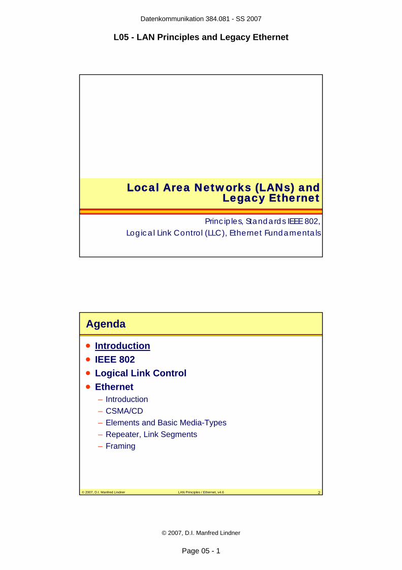
• Local Area Network (LAN), invented late 70`s– initially designed for a common transmission medium
• shared media– high speed
• 4 Mbit/s, 10 Mbit/s, 16 Mbit/s, 100 Mbit/s• nowadays up to 10 Gbit/s
– limited distance• up to some km• hence local
– because of high speed• no network elements with store and forward and no routing• originally no packet switching on layer 2 !!!• note: Ethernet bridging / Ethernet switching invented as L2 packet
switching technology in the late 80´s– therefore simple topologies
• bus, ring, star
© 2007, D.I. Manfred Lindner LAN Principles / Ethernet, v4.6 4
LAN History
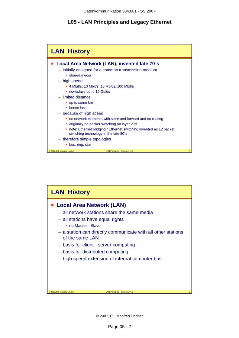
• Local Area Network (LAN)– all network stations share the same media– all stations have equal rights
• no Master - Slave
– a station can directly communicate with all other stations of the same LAN
– basis for client - server computing– basis for distributed computing– high speed extension of internal computer bus
Datenkommunikation 384.081 - SS 2007
L05 - LAN Principles and Legacy Ethernet
© 2007, D.I. Manfred Lindner
Page 05 - 3
© 2007, D.I. Manfred Lindner LAN Principles / Ethernet, v4.6 5
LAN Characteristics
• multipoint line– access control necessary
• Media Access Control (MAC)
– addressing necessary• MAC-Address• unstructured addresses• note: initially no routing requirements !
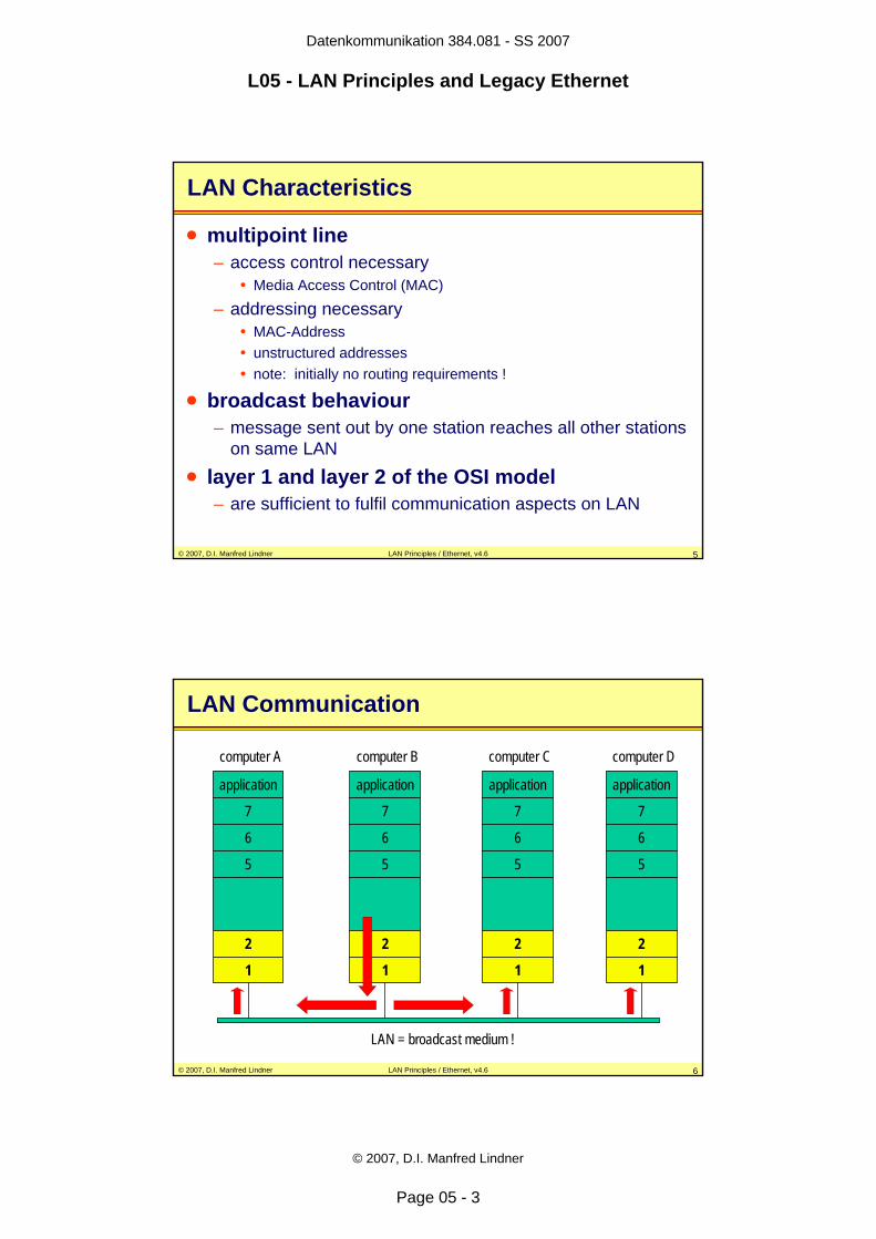
• broadcast behaviour– message sent out by one station reaches all other stations
on same LAN• layer 1 and layer 2 of the OSI model
– are sufficient to fulfil communication aspects on LAN
© 2007, D.I. Manfred Lindner LAN Principles / Ethernet, v4.6 6
LAN Communication
application
7
6
5
2
1
computer A
application
7
6
5
2
1
computer B
application
7
6
5
2
1
computer D
application
7
6
5
2
1
computer C
LAN = broadcast medium !
Datenkommunikation 384.081 - SS 2007
L05 - LAN Principles and Legacy Ethernet
© 2007, D.I. Manfred Lindner
Page 05 - 4
© 2007, D.I. Manfred Lindner LAN Principles / Ethernet, v4.6 7
MAC Addresses
• every station– is identified by unique MAC-address used as source MAC-
address in frames• so called “Burn-In” Address (BIA) in case address is administered
universally by IEEE
• MAC address– 6 Byte (48 bit)– I/G (Individual/Group) bit
• 0 … individual address• 1 … group address
– U/L (Universal/Local) bit• 0 … universal administered• 1 … local administered
© 2007, D.I. Manfred Lindner LAN Principles / Ethernet, v4.6 8
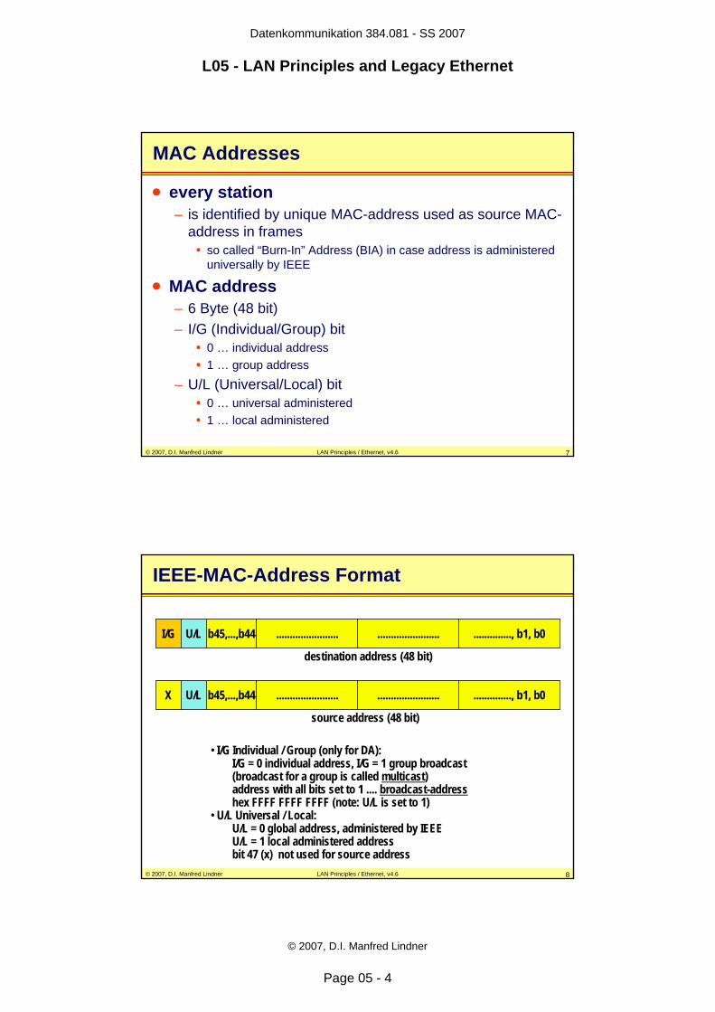
IEEE-MAC-Address Format
I/G U/L b45,...,b44 ....................... ....................... .............., b1, b0
destination address (48 bit)
source address (48 bit)
• I/G Individual / Group (only for DA):I/G = 0 individual address, I/G = 1 group broadcast(broadcast for a group is called multicast)address with all bits set to 1 .... broadcast-addresshex FFFF FFFF FFFF (note: U/L is set to 1)
• U/L Universal / Local:U/L = 0 global address, administered by IEEE U/L = 1 local administered addressbit 47 (x) not used for source address
X U/L b45,...,b44 ....................... ....................... .............., b1, b0
Datenkommunikation 384.081 - SS 2007
L05 - LAN Principles and Legacy Ethernet
© 2007, D.I. Manfred Lindner
Page 05 - 5
© 2007, D.I. Manfred Lindner LAN Principles / Ethernet, v4.6 9
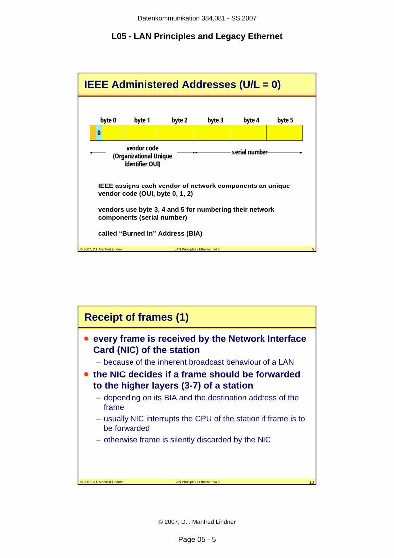
IEEE Administered Addresses (U/L = 0)
0
byte 0 byte 1 byte 2 byte 3 byte 4 byte 5
vendor code (Organizational Unique
Identifier OUI)
serial number
IEEE assigns each vendor of network components an unique vendor code (OUI, byte 0, 1, 2)
vendors use byte 3, 4 and 5 for numbering their network components (serial number)
called “Burned In” Address (BIA)
© 2007, D.I. Manfred Lindner LAN Principles / Ethernet, v4.6 10
Receipt of frames (1)
• every frame is received by the Network Interface Card (NIC) of the station– because of the inherent broadcast behaviour of a LAN
• the NIC decides if a frame should be forwarded to the higher layers (3-7) of a station– depending on its BIA and the destination address of the
frame– usually NIC interrupts the CPU of the station if frame is to
be forwarded– otherwise frame is silently discarded by the NIC
Datenkommunikation 384.081 - SS 2007
L05 - LAN Principles and Legacy Ethernet
© 2007, D.I. Manfred Lindner
Page 05 - 6
© 2007, D.I. Manfred Lindner LAN Principles / Ethernet, v4.6 11
Receipt of frames (2)
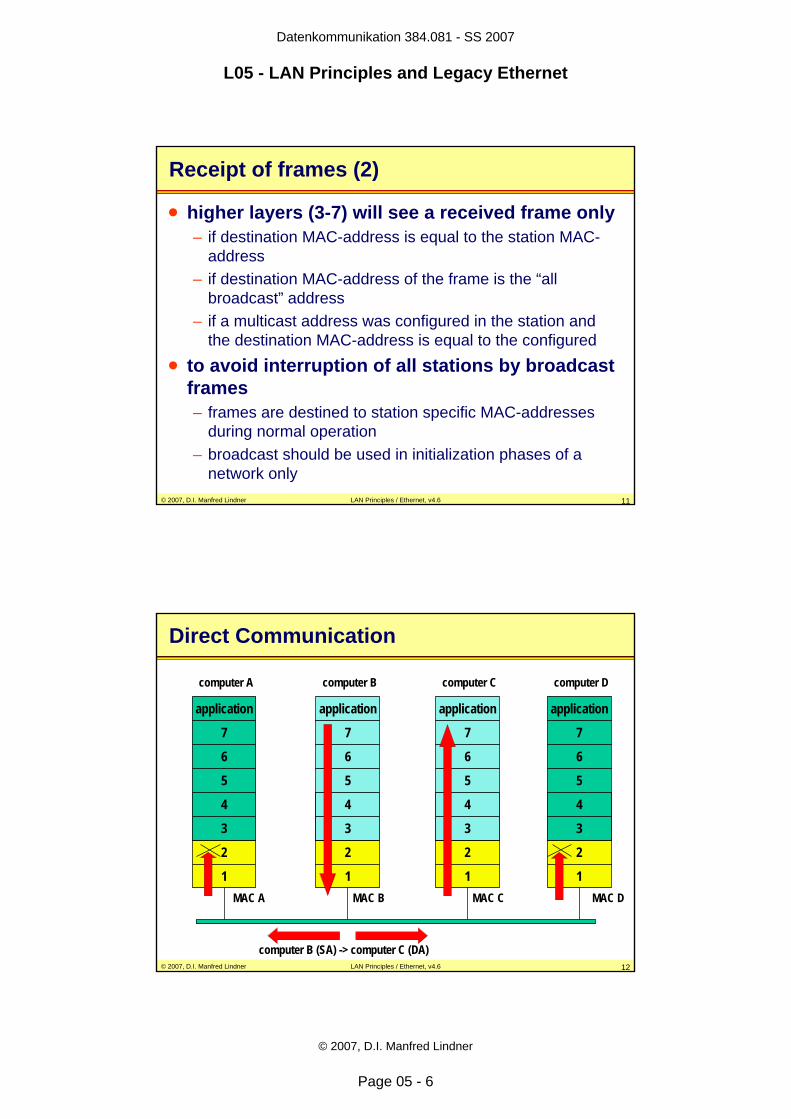
• higher layers (3-7) will see a received frame only– if destination MAC-address is equal to the station MAC-
address– if destination MAC-address of the frame is the “all
broadcast” address – if a multicast address was configured in the station and
the destination MAC-address is equal to the configured• to avoid interruption of all stations by broadcast
frames– frames are destined to station specific MAC-addresses
during normal operation– broadcast should be used in initialization phases of a
network only
© 2007, D.I. Manfred Lindner LAN Principles / Ethernet, v4.6 12
Direct Communication
application
7
6
5
2
1
computer A
application
7
6
5
2
1
computer B
application
7
6
5
2
1
computer D
application
7
6
5
2
1
computer C
computer B (SA) -> computer C (DA)
4
3
4
3
4
3
4
3
MAC A MAC B MAC C MAC D
Datenkommunikation 384.081 - SS 2007
L05 - LAN Principles and Legacy Ethernet
© 2007, D.I. Manfred Lindner
Page 05 - 7
© 2007, D.I. Manfred Lindner LAN Principles / Ethernet, v4.6 13
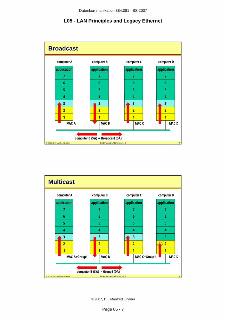
Broadcast
application
7
6
5
2
1
computer A
application
7
6
5
2
1
computer B
application
7
6
5
2
1
computer D
application
7
6
5
2
1
computer C
4
3
4
3
4
3
4
3
MAC A MAC B MAC C MAC D
computer B (SA) -> Broadcast (DA)
© 2007, D.I. Manfred Lindner LAN Principles / Ethernet, v4.6 14
Multicast
application
7
6
5
2
1
computer A
application
7
6
5
2
1
computer B
application
7
6
5
2
1
computer D
application
7
6
5
2
1
computer C
4
3
4
3
4
3
4
3
MAC A+Group1 MAC B MAC DMAC C+Group1
computer B (SA) -> Group1 (DA)
Datenkommunikation 384.081 - SS 2007
L05 - LAN Principles and Legacy Ethernet
© 2007, D.I. Manfred Lindner
Page 05 - 8
© 2007, D.I. Manfred Lindner LAN Principles / Ethernet, v4.6 15
Agenda
• Introduction• IEEE 802• Logical Link Control• Ethernet
– Introduction– CSMA/CD– Elements and Basic Media-Types– Repeater, Link Segments– Framing
© 2007, D.I. Manfred Lindner LAN Principles / Ethernet, v4.6 16
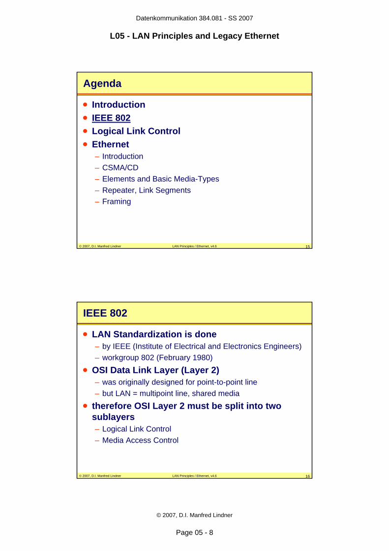
IEEE 802
• LAN Standardization is done– by IEEE (Institute of Electrical and Electronics Engineers)– workgroup 802 (February 1980)
• OSI Data Link Layer (Layer 2)– was originally designed for point-to-point line– but LAN = multipoint line, shared media
• therefore OSI Layer 2 must be split into two sublayers– Logical Link Control– Media Access Control
Datenkommunikation 384.081 - SS 2007
L05 - LAN Principles and Legacy Ethernet
© 2007, D.I. Manfred Lindner
Page 05 - 9
© 2007, D.I. Manfred Lindner LAN Principles / Ethernet, v4.6 17
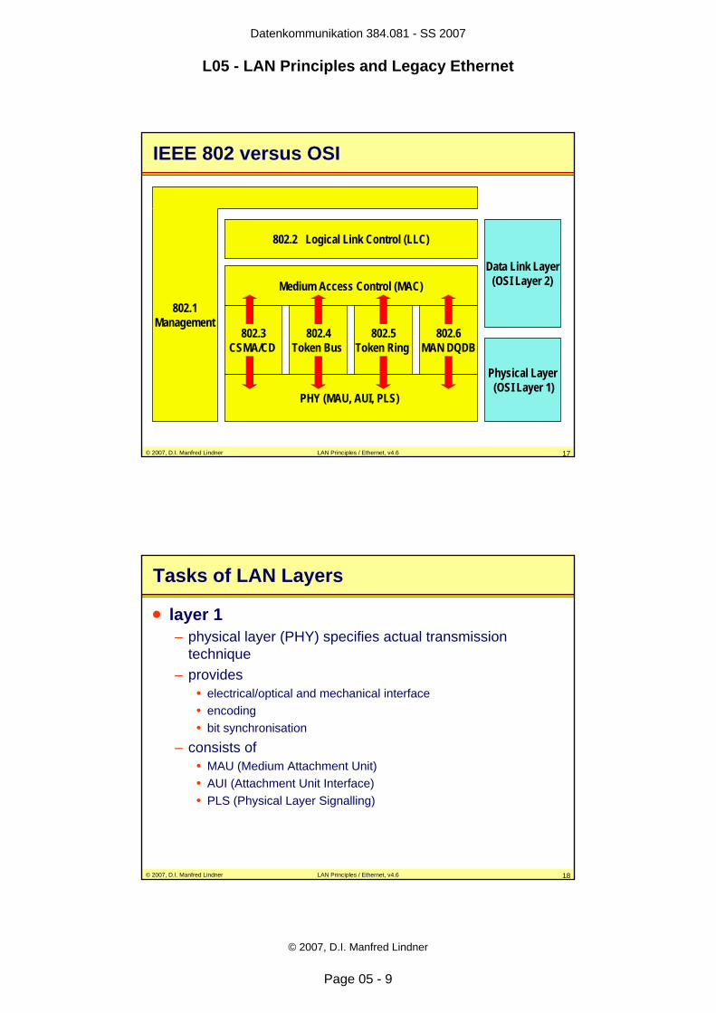
Data Link Layer(OSI Layer 2)
IEEE 802 versus OSI
802.2 Logical Link Control (LLC)
Medium Access Control (MAC)
802.3CSMA/CD
802.4Token Bus
802.5Token Ring
802.6MAN DQDB
802.1Management
PHY (MAU, AUI, PLS)
Physical Layer(OSI Layer 1)
© 2007, D.I. Manfred Lindner LAN Principles / Ethernet, v4.6 18
Tasks of LAN Layers
• layer 1– physical layer (PHY) specifies actual transmission
technique– provides
• electrical/optical and mechanical interface • encoding• bit synchronisation
– consists of• MAU (Medium Attachment Unit)• AUI (Attachment Unit Interface) • PLS (Physical Layer Signalling)
Datenkommunikation 384.081 - SS 2007
L05 - LAN Principles and Legacy Ethernet
© 2007, D.I. Manfred Lindner
Page 05 - 10
© 2007, D.I. Manfred Lindner LAN Principles / Ethernet, v4.6 19
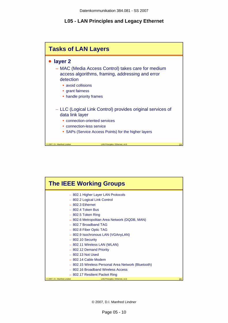
Tasks of LAN Layers
• layer 2– MAC (Media Access Control) takes care for medium
access algorithms, framing, addressing and error detection
• avoid collisions• grant fairness• handle priority frames
– LLC (Logical Link Control) provides original services of data link layer
• connection-oriented services• connection-less service• SAPs (Service Access Points) for the higher layers
© 2007, D.I. Manfred Lindner LAN Principles / Ethernet, v4.6 20
The IEEE Working Groups– 802.1 Higher Layer LAN Protocols– 802.2 Logical Link Control– 802.3 Ethernet– 802.4 Token Bus– 802.5 Token Ring– 802.6 Metropolitan Area Network (DQDB, MAN)– 802.7 Broadband TAG– 802.8 Fiber Optic TAG– 802.9 Isochronous LAN (VGAnyLAN)– 802.10 Security– 802.11 Wireless LAN (WLAN)– 802.12 Demand Priority– 802.13 Not Used– 802.14 Cable Modem– 802.15 Wireless Personal Area Network (Bluetooth)– 802.16 Broadband Wireless Access– 802.17 Resilient Packet Ring
Datenkommunikation 384.081 - SS 2007
L05 - LAN Principles and Legacy Ethernet
© 2007, D.I. Manfred Lindner
Page 05 - 11
© 2007, D.I. Manfred Lindner LAN Principles / Ethernet, v4.6 21
IEEE 802.1 Standards
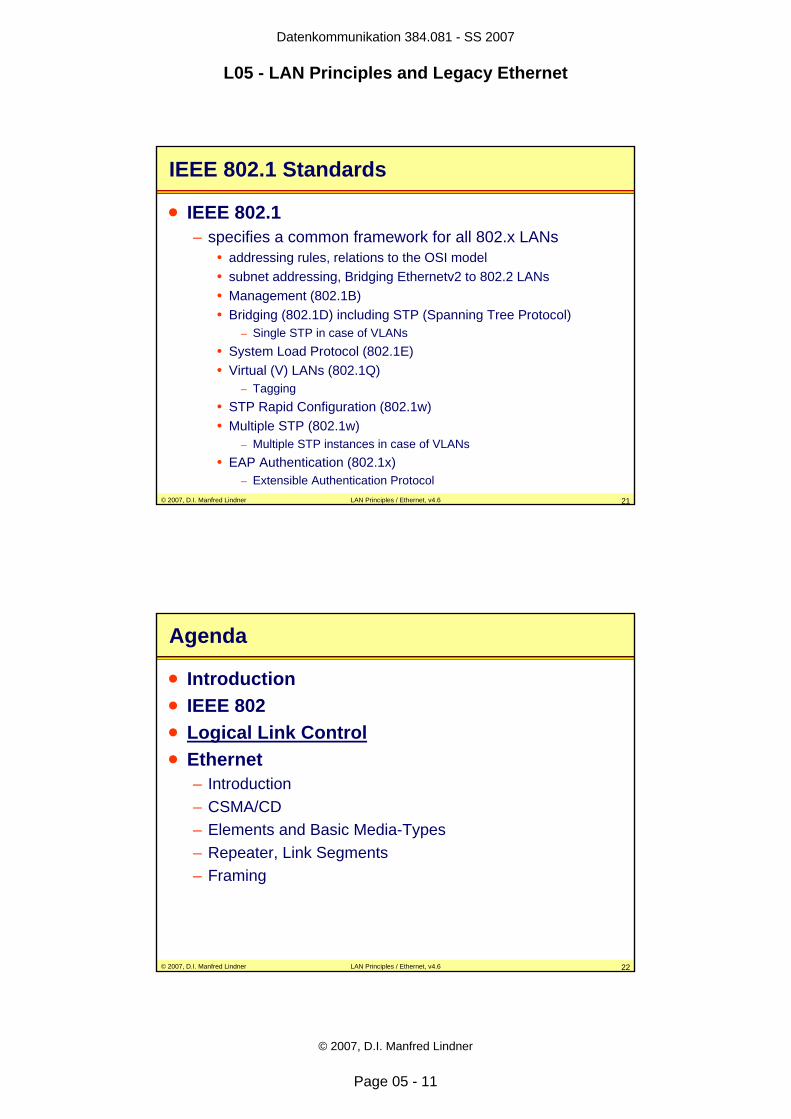
• IEEE 802.1– specifies a common framework for all 802.x LANs
• addressing rules, relations to the OSI model• subnet addressing, Bridging Ethernetv2 to 802.2 LANs• Management (802.1B)• Bridging (802.1D) including STP (Spanning Tree Protocol)
– Single STP in case of VLANs• System Load Protocol (802.1E)• Virtual (V) LANs (802.1Q)
– Tagging• STP Rapid Configuration (802.1w)• Multiple STP (802.1w)
– Multiple STP instances in case of VLANs• EAP Authentication (802.1x)
– Extensible Authentication Protocol
© 2007, D.I. Manfred Lindner LAN Principles / Ethernet, v4.6 22
Agenda
• Introduction• IEEE 802• Logical Link Control• Ethernet
– Introduction– CSMA/CD– Elements and Basic Media-Types– Repeater, Link Segments– Framing
Datenkommunikation 384.081 - SS 2007
L05 - LAN Principles and Legacy Ethernet
© 2007, D.I. Manfred Lindner
Page 05 - 12
© 2007, D.I. Manfred Lindner LAN Principles / Ethernet, v4.6 23
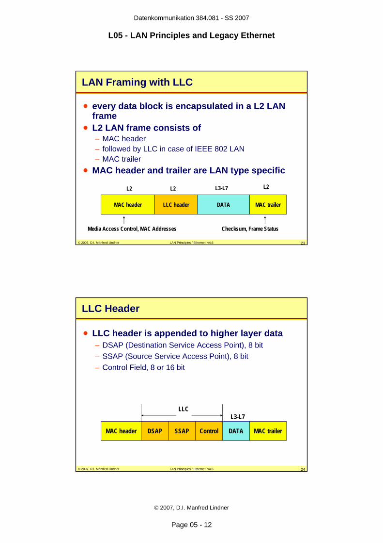
LAN Framing with LLC
• every data block is encapsulated in a L2 LAN frame
• L2 LAN frame consists of– MAC header– followed by LLC in case of IEEE 802 LAN– MAC trailer
• MAC header and trailer are LAN type specific
MAC header LLC header MAC trailerDATA
L3-L7
Media Access Control, MAC Addresses Checksum, Frame Status
L2 L2 L2
© 2007, D.I. Manfred Lindner LAN Principles / Ethernet, v4.6 24
LLC Header
• LLC header is appended to higher layer data– DSAP (Destination Service Access Point), 8 bit– SSAP (Source Service Access Point), 8 bit– Control Field, 8 or 16 bit
MAC header DSAP SSAP Control MAC trailerDATA
LLCL3-L7

Datenkommunikation 384.081 - SS 2007
L05 - LAN Principles and Legacy Ethernet
© 2007, D.I. Manfred Lindner
Page 05 - 13
© 2007, D.I. Manfred Lindner LAN Principles / Ethernet, v4.6 25
DSAP and SSAP
• a IEEE 802 LAN– can be used by different protocol families sharing the
same communication media• e.g. TCP/IP parallel to Novell IPX, IBM SNA, NetBeui, Appletalk
• DSAP and SSAP– identify the higher level protocol family, which is the
destination and the source of the given frame – protocol type or protocol stack identifier
© 2007, D.I. Manfred Lindner LAN Principles / Ethernet, v4.6 26
Protocol Stack Distinction
TCP/IPApplication
2
1
computer B computer C
TCP
IP
MAC B MAC C
SPX
IPX
2
1
NovellApplication
TCP/IPApplication
TCP
IP
SPX
IPX
NovellApplication
SSAP = 06 SSAP = E0 DSAP = 06 DSAP = E0
SA B DA C SSAP 06 DSAP 06
SA B DA C SSAP E0 DSAP E0
Datenkommunikation 384.081 - SS 2007
L05 - LAN Principles and Legacy Ethernet
© 2007, D.I. Manfred Lindner
Page 05 - 14
© 2007, D.I. Manfred Lindner LAN Principles / Ethernet, v4.6 27
LLC Control Field
• LLC Control field and protocol procedures are very similar to HDLC
• remember: HDLC procedures allow connection-less and connection-oriented services on a layer 2 link
• connection-less mode is used by – IP, IPX, AppleTalk, etc
• connection-oriented mode is used by– SNA over LLC Type 2– NetBIOS over LLC Type 2 (NetBeui)
• e.g. Microsoft Network
© 2007, D.I. Manfred Lindner LAN Principles / Ethernet, v4.6 28
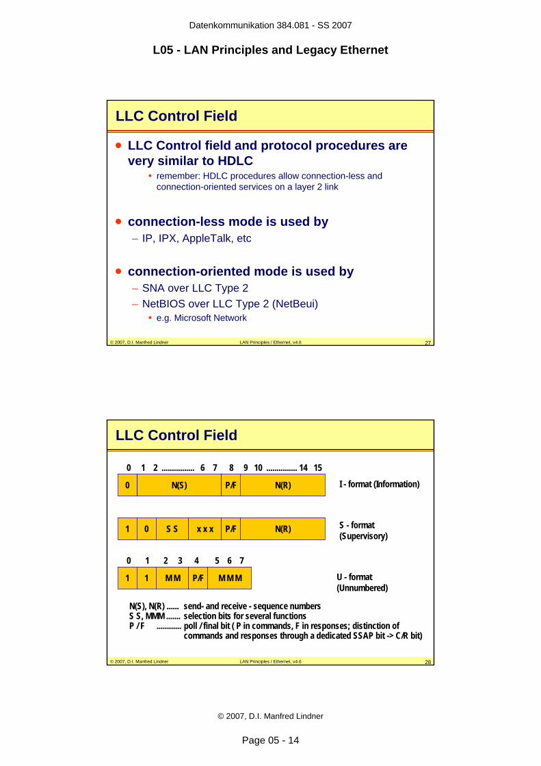
LLC Control Field
N(S) N(R)P/F
1 0 S S x x x
0
P/F N(R)
1 1 M M P/F M M M
0 1 2 ................ 6 7 8 9 10 ............... 14 15
0 1 2 3 4 5 6 7
I - format (Information)
S - format (Supervisory)
U - format (Unnumbered)
N(S), N(R) ...... send- and receive - sequence numbersS S, MMM ....... selection bits for several functionsP / F ............ poll / final bit ( P in commands, F in responses; distinction of
commands and responses through a dedicated SSAP bit -> C/R bit)
Datenkommunikation 384.081 - SS 2007
L05 - LAN Principles and Legacy Ethernet
© 2007, D.I. Manfred Lindner
Page 05 - 15
© 2007, D.I. Manfred Lindner LAN Principles / Ethernet, v4.6 29
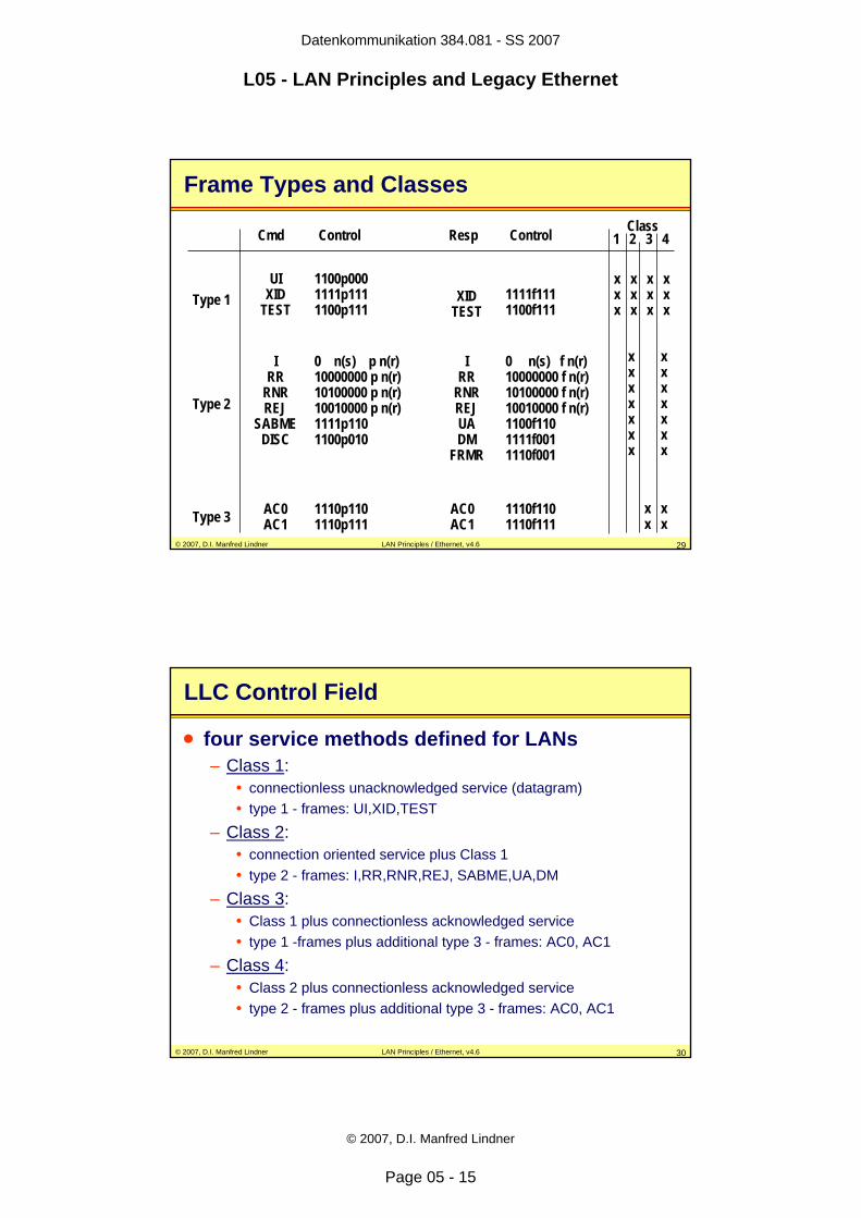
Frame Types and Classes
UIXID
TESTXID
TESTType 1
IRR
RNRREJUADM
FRMR
Type 2
IRR
RNRREJ
SABMEDISC
Cmd Resp
1100p0001111p1111100p111
0 n(s) p n(r)10000000 p n(r)10100000 p n(r)10010000 p n(r)1111p1101100p010
0 n(s) f n(r)10000000 f n(r)10100000 f n(r)10010000 f n(r)1100f1101111f0011110f001
1111f1111100f111
Control Control
Type 3 AC0AC1
1110p1101110p111
AC0AC1
1110f1101110f111
1 2 3 4
x x x xx x x xx x x x
x xx xx xx xx xx xx x
x xx x
Class
© 2007, D.I. Manfred Lindner LAN Principles / Ethernet, v4.6 30
LLC Control Field
• four service methods defined for LANs– Class 1:
• connectionless unacknowledged service (datagram)• type 1 - frames: UI,XID,TEST
– Class 2:• connection oriented service plus Class 1• type 2 - frames: I,RR,RNR,REJ, SABME,UA,DM
– Class 3:• Class 1 plus connectionless acknowledged service• type 1 -frames plus additional type 3 - frames: AC0, AC1
– Class 4:• Class 2 plus connectionless acknowledged service• type 2 - frames plus additional type 3 - frames: AC0, AC1
Datenkommunikation 384.081 - SS 2007
L05 - LAN Principles and Legacy Ethernet
© 2007, D.I. Manfred Lindner
Page 05 - 16
© 2007, D.I. Manfred Lindner LAN Principles / Ethernet, v4.6 31
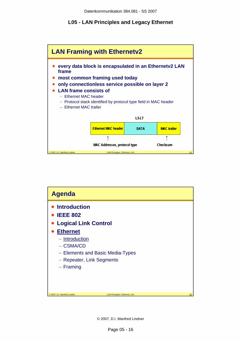
LAN Framing with Ethernetv2
• every data block is encapsulated in an Ethernetv2 LAN frame
• most common framing used today• only connectionless service possible on layer 2• LAN frame consists of
– Ethernet MAC header– Protocol stack identified by protocol type field in MAC header– Ethernet MAC trailer
Ethernet MAC header MAC trailerDATA
L3-L7
MAC Addresses, protocol type Checksum
© 2007, D.I. Manfred Lindner LAN Principles / Ethernet, v4.6 32
Agenda
• Introduction• IEEE 802• Logical Link Control• Ethernet
– Introduction– CSMA/CD– Elements and Basic Media-Types– Repeater, Link Segments– Framing
Datenkommunikation 384.081 - SS 2007
L05 - LAN Principles and Legacy Ethernet
© 2007, D.I. Manfred Lindner
Page 05 - 17
© 2007, D.I. Manfred Lindner LAN Principles / Ethernet, v4.6 33
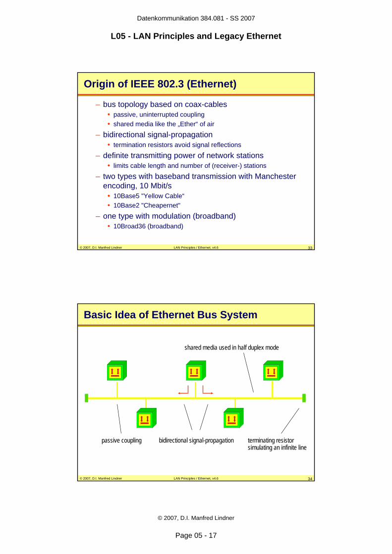
Origin of IEEE 802.3 (Ethernet)
– bus topology based on coax-cables• passive, uninterrupted coupling• shared media like the „Ether“ of air
– bidirectional signal-propagation• termination resistors avoid signal reflections
– definite transmitting power of network stations• limits cable length and number of (receiver-) stations
– two types with baseband transmission with Manchester encoding, 10 Mbit/s
• 10Base5 "Yellow Cable“• 10Base2 "Cheapernet"
– one type with modulation (broadband)• 10Broad36 (broadband)
© 2007, D.I. Manfred Lindner LAN Principles / Ethernet, v4.6 34
Basic Idea of Ethernet Bus System
terminating resistorsimulating an infinite line
passive coupling bidirectional signal-propagation
shared media used in half duplex mode
Datenkommunikation 384.081 - SS 2007
L05 - LAN Principles and Legacy Ethernet
© 2007, D.I. Manfred Lindner
Page 05 - 18
© 2007, D.I. Manfred Lindner LAN Principles / Ethernet, v4.6 35
Agenda
• Introduction• IEEE 802• Logical Link Control• Ethernet
– Introduction– CSMA/CD– Elements and Basic Media-Types– Repeater, Link Segments– Framing
© 2007, D.I. Manfred Lindner LAN Principles / Ethernet, v4.6 36
Media Access Control of Ethernet 1
• CSMA/CD– Carrier Sense Multiple Access / Collision Detection– access control based on contention– network stations listen to the bus before they start a
transmission– network stations can detect ongoing transmission (CS)
and will not start own transmission before ongoing transmission is over
– but still simultaneous transmissions (MA) cause collisions (bus conflict)
– collisions are detected (CD) by observing the DC-level on the medium
Datenkommunikation 384.081 - SS 2007
L05 - LAN Principles and Legacy Ethernet
© 2007, D.I. Manfred Lindner
Page 05 - 19
© 2007, D.I. Manfred Lindner LAN Principles / Ethernet, v4.6 37
Media Access Control of Ethernet 2
• conflict resolution– aborting of transmission by all involved stations– sending of a JAM-signal (32 bit)
• to make sure that every station can recognize the collision• collision is spread to a minimum length
– starting a random number generator to create a timeout value
truncated binary exponential backoff algorithm (the more often a collision occurs the larger is the range for the random number)
– after timeout expired, station attempts a retransmission – number of retransmission-trials is limited to 16
• after 16 collisions in a sequence a error is signalled to the higher layer
© 2007, D.I. Manfred Lindner LAN Principles / Ethernet, v4.6 38
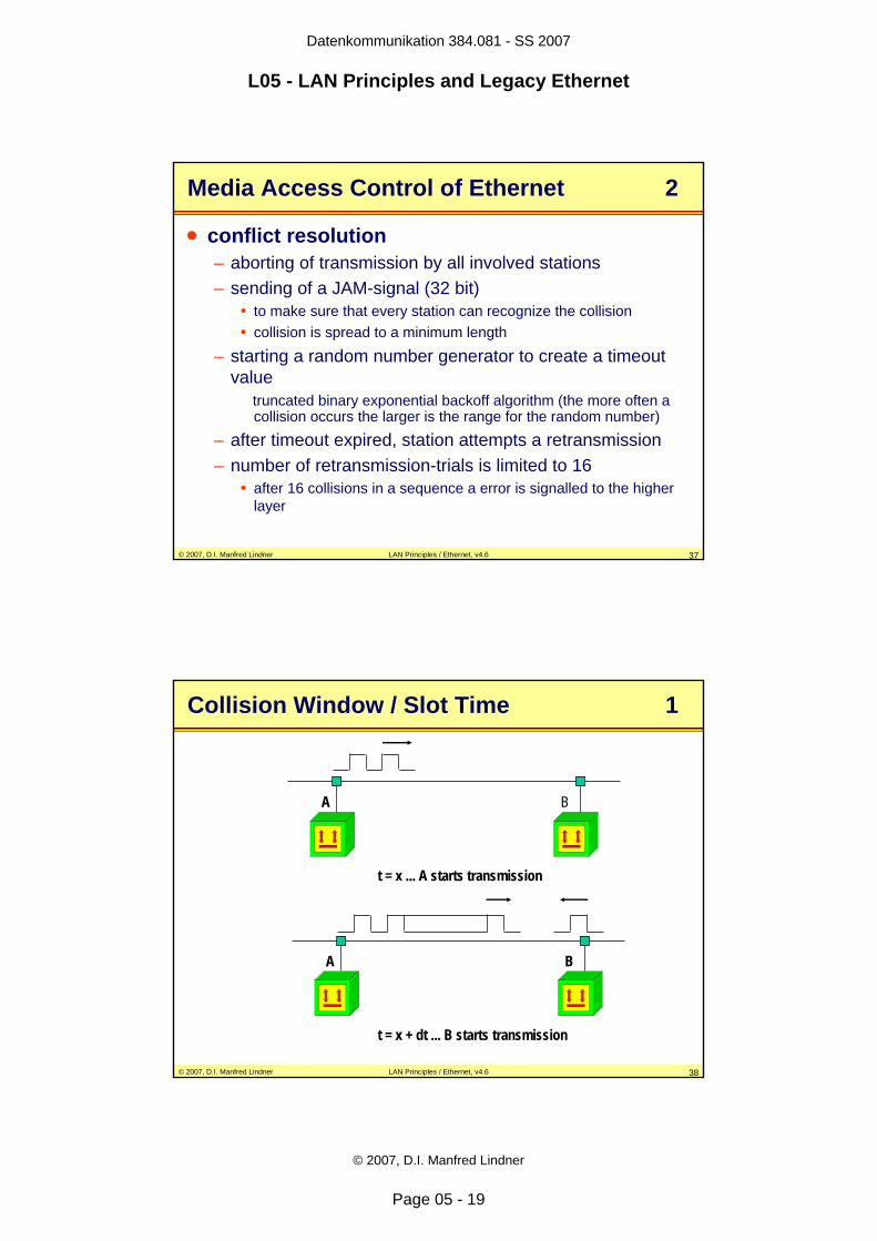
Collision Window / Slot Time 1
t = x ... A starts transmission
A B
t = x + dt ... B starts transmission
A B
Datenkommunikation 384.081 - SS 2007
L05 - LAN Principles and Legacy Ethernet
© 2007, D.I. Manfred Lindner
Page 05 - 20
© 2007, D.I. Manfred Lindner LAN Principles / Ethernet, v4.6 39
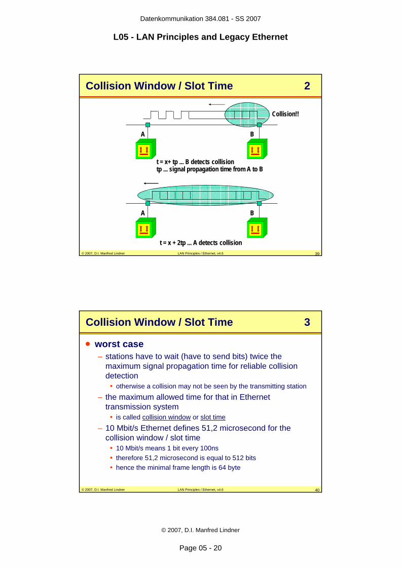
Collision Window / Slot Time 2
t = x+ tp ... B detects collisiontp ... signal propagation time from A to B
A B
Collision!!
A B
t = x + 2tp ... A detects collision
© 2007, D.I. Manfred Lindner LAN Principles / Ethernet, v4.6 40
Collision Window / Slot Time 3
• worst case– stations have to wait (have to send bits) twice the
maximum signal propagation time for reliable collision detection
• otherwise a collision may not be seen by the transmitting station
– the maximum allowed time for that in Ethernet transmission system
• is called collision window or slot time
– 10 Mbit/s Ethernet defines 51,2 microsecond for the collision window / slot time
• 10 Mbit/s means 1 bit every 100ns• therefore 51,2 microsecond is equal to 512 bits• hence the minimal frame length is 64 byte
Datenkommunikation 384.081 - SS 2007
L05 - LAN Principles and Legacy Ethernet
© 2007, D.I. Manfred Lindner
Page 05 - 21
© 2007, D.I. Manfred Lindner LAN Principles / Ethernet, v4.6 41
Collision Window / Slot Time 4
• there is an interdependence– maximum propagation time (cable and electronic
components) or slot time, data rate, cable length and minimum frame size
– if you choose one parameter, the others will follow• the request for reliable collision detection during
sending of a frame and the definition of a given Ethernet slot-time– limits the physical distance (network diameter) of Ethernet
LANs for 10 Mbit/s• around 2500 - 3000 meters
• the request for fairness– limits the maximum frame size, too– 1518 byte is the maximum allowed frame size
© 2007, D.I. Manfred Lindner LAN Principles / Ethernet, v4.6 42
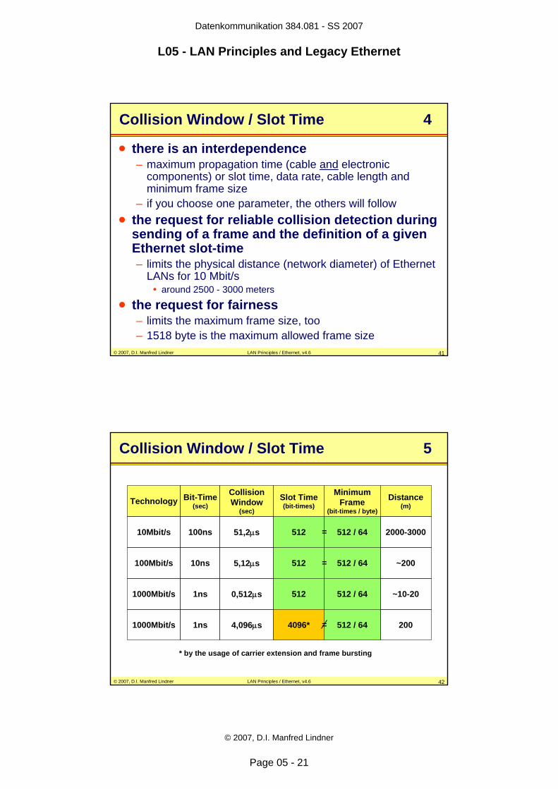
Collision Window / Slot Time 5
Technology Bit-Time(sec)
CollisionWindow
(sec)
MinimumFrame
(bit-times / byte)
Slot Time(bit-times)
Distance(m)
10Mbit/s 100ns 51,2μs 512 / 64512 2000-3000
100Mbit/s 10ns 5,12μs 512 / 64512 ~200
1000Mbit/s 1ns 0,512μs 512 / 64512 ~10-20
1000Mbit/s 1ns 4,096μs 512 / 644096* 200
* by the usage of carrier extension and frame bursting
=
=
=
Datenkommunikation 384.081 - SS 2007
L05 - LAN Principles and Legacy Ethernet
© 2007, D.I. Manfred Lindner
Page 05 - 22
© 2007, D.I. Manfred Lindner LAN Principles / Ethernet, v4.6 43
Exponential Backoff Details
• Provides maximal utilization of bandwidth– After collision, set basic delay = slot time– Total delay = basic delay * random– 0 <= random < 2k
• k = min (number of transmission attempts, 10)
• After 16 successive collisions– Frame is discarded, error message to higher layer and
next frame is processed, if any• Truncated Backoff (k<=10)
– 1024 potential "slots" for a station– Thus maximum 1024 stations allowed on half-duplex
Ethernet
© 2007, D.I. Manfred Lindner LAN Principles / Ethernet, v4.6 44
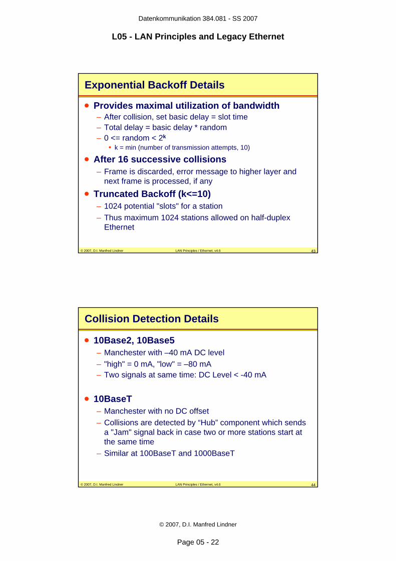
Collision Detection Details
• 10Base2, 10Base5– Manchester with –40 mA DC level– "high" = 0 mA, "low" = –80 mA– Two signals at same time: DC Level < -40 mA
• 10BaseT– Manchester with no DC offset– Collisions are detected by “Hub” component which sends
a "Jam" signal back in case two or more stations start at the same time
– Similar at 100BaseT and 1000BaseT
Datenkommunikation 384.081 - SS 2007
L05 - LAN Principles and Legacy Ethernet
© 2007, D.I. Manfred Lindner
Page 05 - 23
© 2007, D.I. Manfred Lindner LAN Principles / Ethernet, v4.6 45
Agenda
• Introduction• IEEE 802• Logical Link Control• Ethernet
– Introduction– CSMA/CD– Elements and Basic Media-Types– Repeater, Link Segments– Framing
© 2007, D.I. Manfred Lindner LAN Principles / Ethernet, v4.6 46
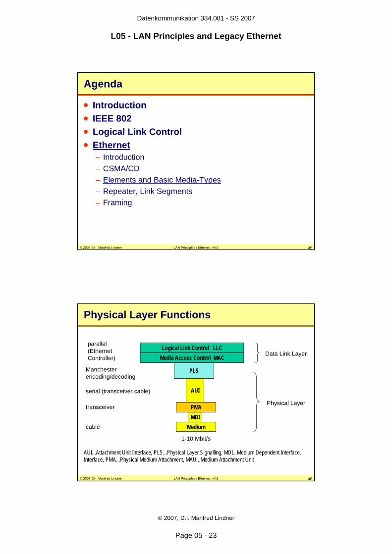
Physical Layer Functions
Logical Link Control LLCMedia Access Control MAC
PLS
AUI
PMAMDI
Medium
Data Link Layer
Physical Layer
1-10 Mbit/s
AUI...Attachment Unit Interface, PLS...Physical Layer Signalling, MDI...Medium Dependent Interface, Interface, PMA...Physical Medium Attachment, MAU...Medium Attachment Unit
transceiver
serial (transceiver cable)
parallel (Ethernet Controller)
Manchester encoding/decoding
cable
Datenkommunikation 384.081 - SS 2007
L05 - LAN Principles and Legacy Ethernet
© 2007, D.I. Manfred Lindner
Page 05 - 24
© 2007, D.I. Manfred Lindner LAN Principles / Ethernet, v4.6 47
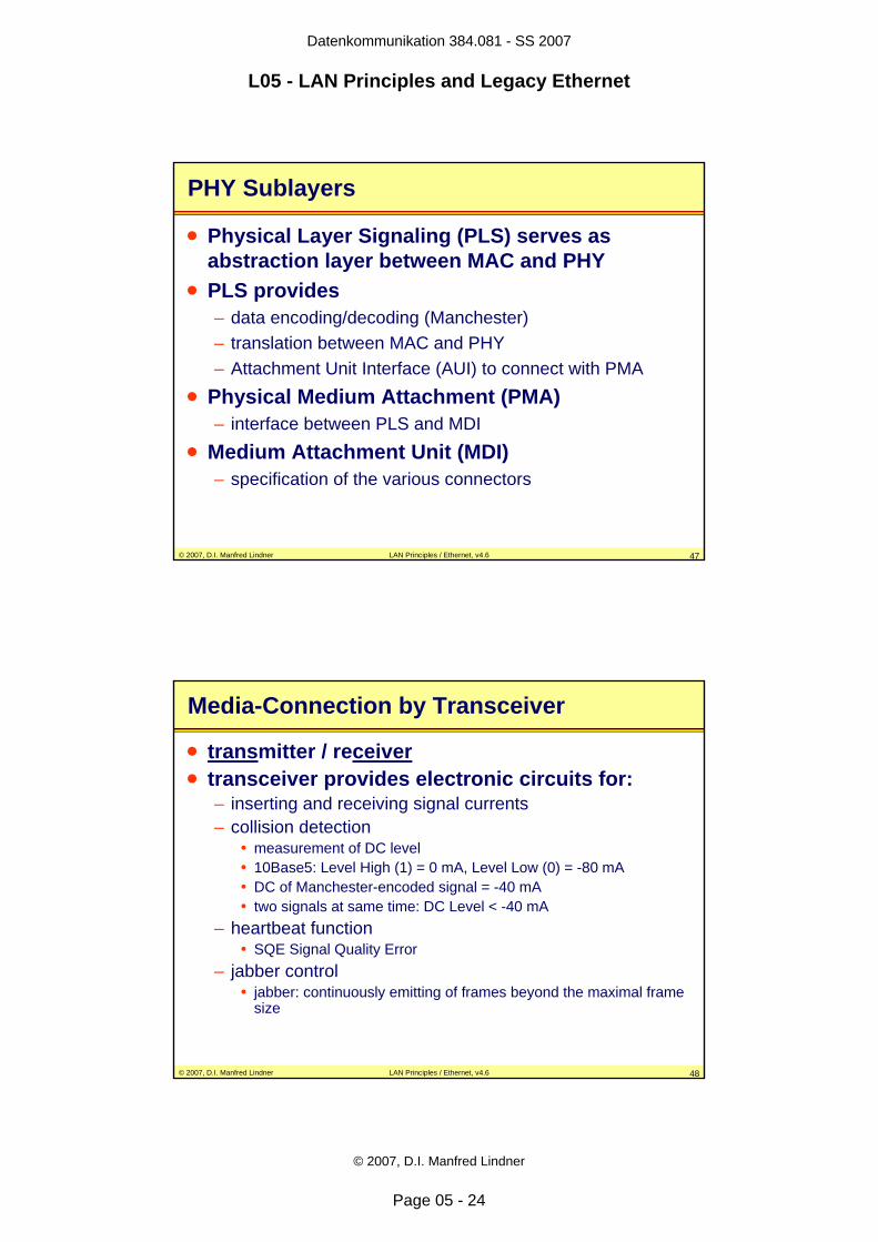
PHY Sublayers
• Physical Layer Signaling (PLS) serves as abstraction layer between MAC and PHY
• PLS provides– data encoding/decoding (Manchester)– translation between MAC and PHY– Attachment Unit Interface (AUI) to connect with PMA
• Physical Medium Attachment (PMA)– interface between PLS and MDI
• Medium Attachment Unit (MDI)– specification of the various connectors
© 2007, D.I. Manfred Lindner LAN Principles / Ethernet, v4.6 48
Media-Connection by Transceiver
• transmitter / receiver• transceiver provides electronic circuits for:
– inserting and receiving signal currents– collision detection
• measurement of DC level• 10Base5: Level High (1) = 0 mA, Level Low (0) = -80 mA• DC of Manchester-encoded signal = -40 mA• two signals at same time: DC Level < -40 mA
– heartbeat function • SQE Signal Quality Error
– jabber control • jabber: continuously emitting of frames beyond the maximal frame
size
Datenkommunikation 384.081 - SS 2007
L05 - LAN Principles and Legacy Ethernet
© 2007, D.I. Manfred Lindner
Page 05 - 25
© 2007, D.I. Manfred Lindner LAN Principles / Ethernet, v4.6 49
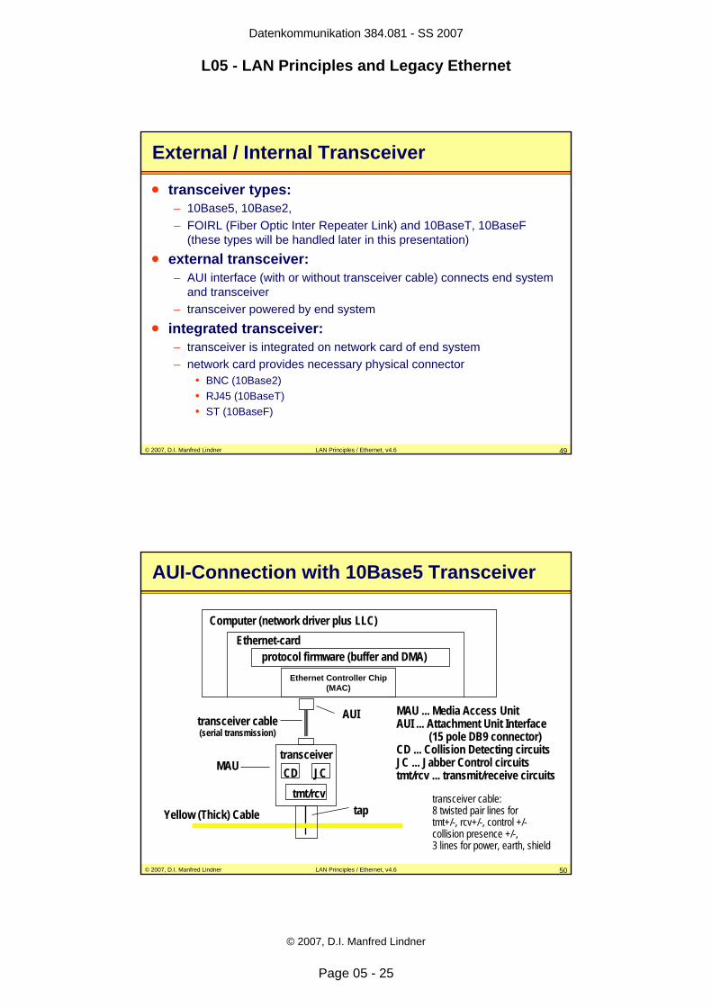
External / Internal Transceiver
• transceiver types:– 10Base5, 10Base2,– FOIRL (Fiber Optic Inter Repeater Link) and 10BaseT, 10BaseF
(these types will be handled later in this presentation)
• external transceiver:– AUI interface (with or without transceiver cable) connects end system
and transceiver – transceiver powered by end system
• integrated transceiver:– transceiver is integrated on network card of end system– network card provides necessary physical connector
• BNC (10Base2)• RJ45 (10BaseT)• ST (10BaseF)
© 2007, D.I. Manfred Lindner LAN Principles / Ethernet, v4.6 50
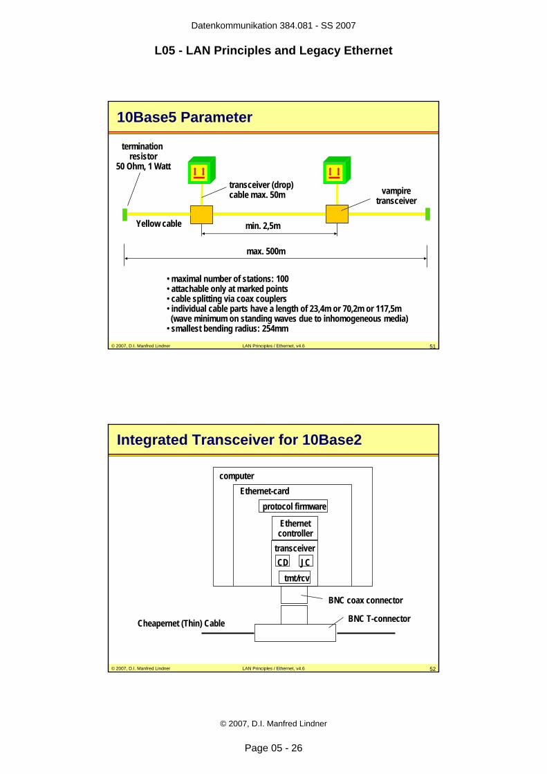
AUI-Connection with 10Base5 Transceiver
Ethernet-cardComputer (network driver plus LLC)
protocol firmware (buffer and DMA)
tmt/rcvCD JC
transceiver
AUItransceiver cable(serial transmission)
Yellow (Thick) Cable tap
MAU
Ethernet Controller Chip(MAC)
MAU ... Media Access UnitAUI ... Attachment Unit Interface
(15 pole DB9 connector)CD ... Collision Detecting circuitsJC ... Jabber Control circuitstmt/rcv ... transmit/receive circuits
transceiver cable:8 twisted pair lines for tmt+/-, rcv+/-, control +/-collision presence +/-,3 lines for power, earth, shield
Datenkommunikation 384.081 - SS 2007
L05 - LAN Principles and Legacy Ethernet
© 2007, D.I. Manfred Lindner
Page 05 - 26
© 2007, D.I. Manfred Lindner LAN Principles / Ethernet, v4.6 51
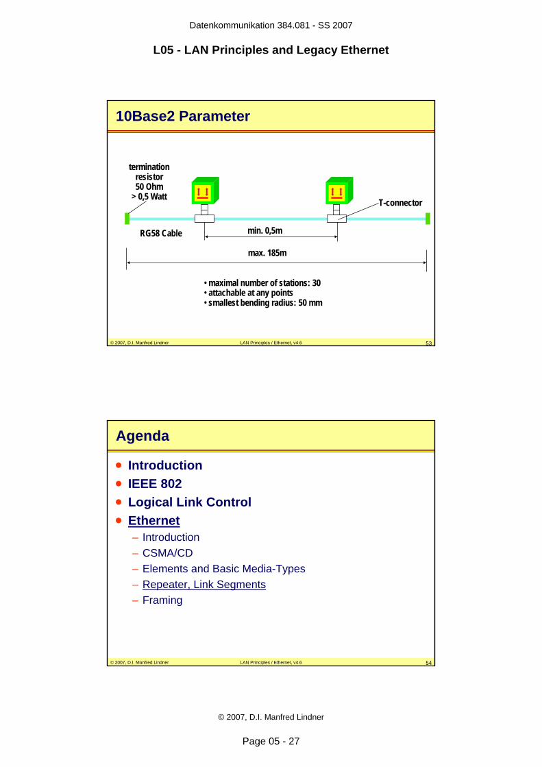
10Base5 Parameter
min. 2,5m
max. 500m
transceiver (drop)cable max. 50m vampire
transceiver
termination resistor
50 Ohm, 1 Watt
Yellow cable
• maximal number of stations: 100• attachable only at marked points• cable splitting via coax couplers • individual cable parts have a length of 23,4m or 70,2m or 117,5m(wave minimum on standing waves due to inhomogeneous media)
• smallest bending radius: 254mm
© 2007, D.I. Manfred Lindner LAN Principles / Ethernet, v4.6 52
Integrated Transceiver for 10Base2
Ethernet-cardcomputer
Ethernetcontroller
protocol firmware
tmt/rcvCD JC
transceiver
Cheapernet (Thin) Cable
BNC coax connector
BNC T-connector
Datenkommunikation 384.081 - SS 2007
L05 - LAN Principles and Legacy Ethernet
© 2007, D.I. Manfred Lindner
Page 05 - 27
© 2007, D.I. Manfred Lindner LAN Principles / Ethernet, v4.6 53
10Base2 Parameter
min. 0,5m
max. 185m
termination resistor50 Ohm
> 0,5 Watt
• maximal number of stations: 30• attachable at any points• smallest bending radius: 50 mm
RG58 Cable
T-connector
© 2007, D.I. Manfred Lindner LAN Principles / Ethernet, v4.6 54
Agenda
• Introduction• IEEE 802• Logical Link Control• Ethernet
– Introduction– CSMA/CD– Elements and Basic Media-Types– Repeater, Link Segments– Framing
Datenkommunikation 384.081 - SS 2007
L05 - LAN Principles and Legacy Ethernet
© 2007, D.I. Manfred Lindner
Page 05 - 28
© 2007, D.I. Manfred Lindner LAN Principles / Ethernet, v4.6 55
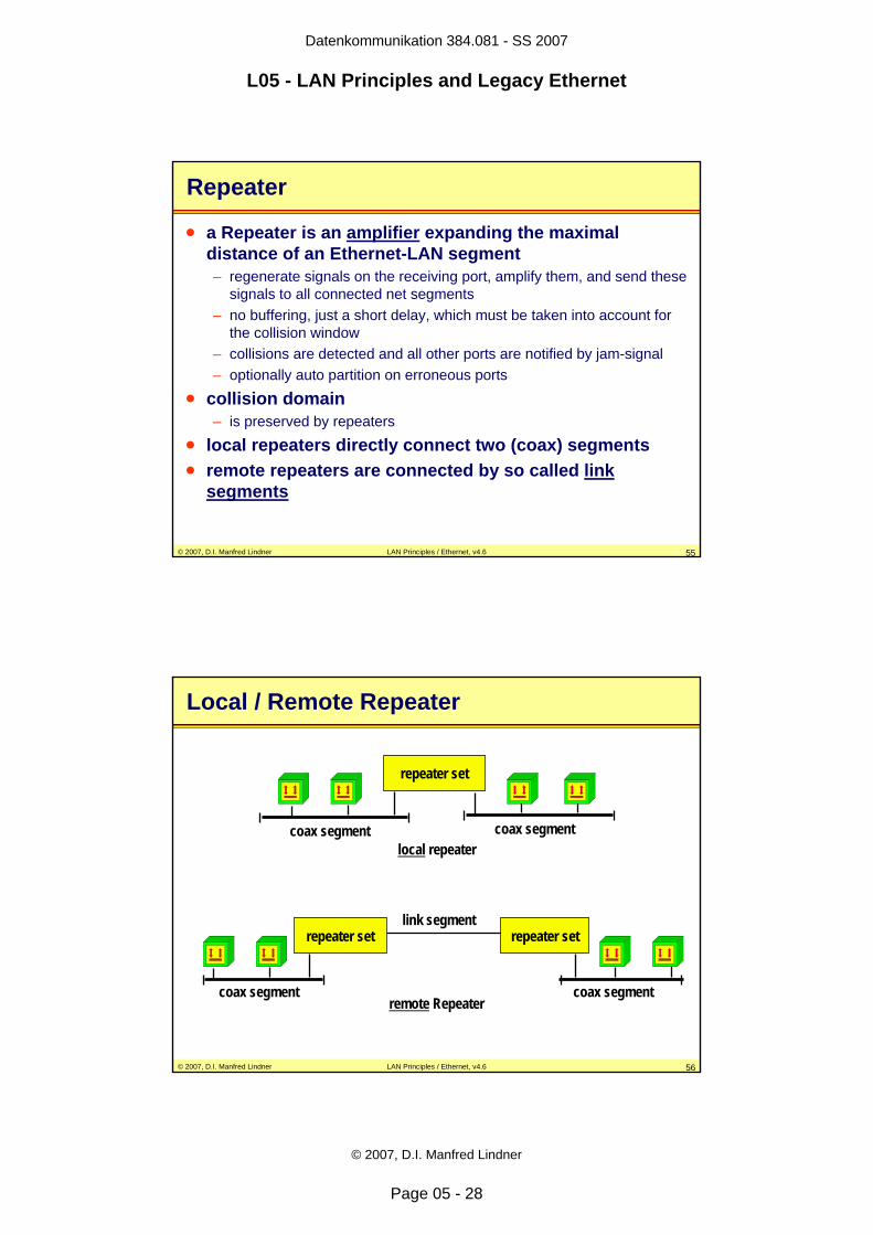
Repeater
• a Repeater is an amplifier expanding the maximal distance of an Ethernet-LAN segment– regenerate signals on the receiving port, amplify them, and send these
signals to all connected net segments– no buffering, just a short delay, which must be taken into account for
the collision window– collisions are detected and all other ports are notified by jam-signal– optionally auto partition on erroneous ports
• collision domain– is preserved by repeaters
• local repeaters directly connect two (coax) segments• remote repeaters are connected by so called link
segments
© 2007, D.I. Manfred Lindner LAN Principles / Ethernet, v4.6 56
Local / Remote Repeater
coax segment coax segment
coax segment coax segment
link segment
local repeater
remote Repeater
repeater set repeater set
repeater set
Datenkommunikation 384.081 - SS 2007
L05 - LAN Principles and Legacy Ethernet
© 2007, D.I. Manfred Lindner
Page 05 - 29
© 2007, D.I. Manfred Lindner LAN Principles / Ethernet, v4.6 57
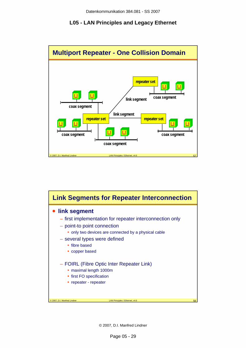
Multiport Repeater - One Collision Domain
coax segment
coax segment
coax segment coax segment
link segmentrepeater set repeater set
coax segment
repeater set
link segment
© 2007, D.I. Manfred Lindner LAN Principles / Ethernet, v4.6 58
Link Segments for Repeater Interconnection
• link segment– first implementation for repeater interconnection only– point-to point connection
• only two devices are connected by a physical cable
– several types were defined• fibre based• copper based
– FOIRL (Fibre Optic Inter Repeater Link)• maximal length 1000m• first FO specification• repeater - repeater
Datenkommunikation 384.081 - SS 2007
L05 - LAN Principles and Legacy Ethernet
© 2007, D.I. Manfred Lindner
Page 05 - 30
© 2007, D.I. Manfred Lindner LAN Principles / Ethernet, v4.6 59
Link Segments for Repeater Interconnection
• types cont.– 10BaseFL (Fibre)
• asynchronous• maximal length 2000m• repeater - repeater, end system - multiport repeater
– 10BaseFB (Fibre)• synchronous (idle signals during communication pauses)• maximal length 2000m• for repeater - repeater links only• developed to overcome limitation based on repeater rules by
defining a repeater less backbone infrastructure
– 10BaseFP (Fibre)• passive hub, no active repeater function (remark: active means
electrically powered)
© 2007, D.I. Manfred Lindner LAN Principles / Ethernet, v4.6 60
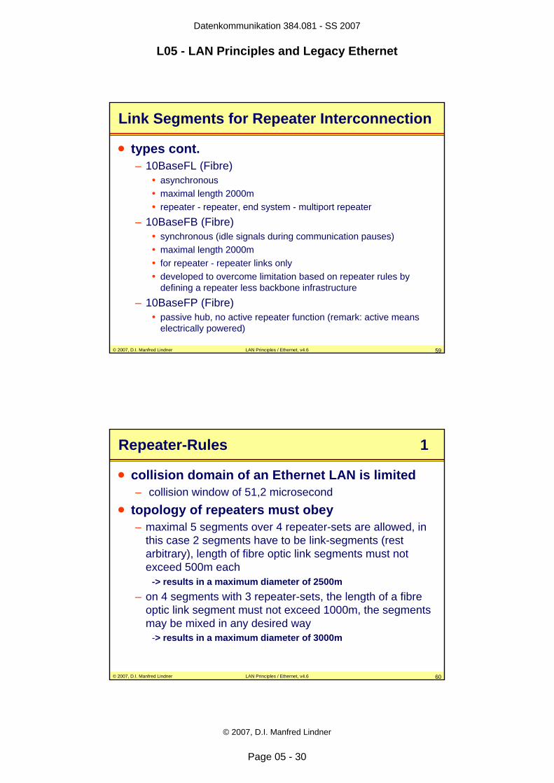
Repeater-Rules 1
• collision domain of an Ethernet LAN is limited– collision window of 51,2 microsecond
• topology of repeaters must obey– maximal 5 segments over 4 repeater-sets are allowed, in
this case 2 segments have to be link-segments (rest arbitrary), length of fibre optic link segments must not exceed 500m each
-> results in a maximum diameter of 2500m– on 4 segments with 3 repeater-sets, the length of a fibre
optic link segment must not exceed 1000m, the segments may be mixed in any desired way
-> results in a maximum diameter of 3000m
Datenkommunikation 384.081 - SS 2007
L05 - LAN Principles and Legacy Ethernet
© 2007, D.I. Manfred Lindner
Page 05 - 31
© 2007, D.I. Manfred Lindner LAN Principles / Ethernet, v4.6 61
Repeater-Rules 2
10 Base FL
10 Base 5 10 Base 5 10 Base 5
10 Base FL
500m 500m
500m 500m500m
RRRR
10 Base FL
10 Base 5 10 Base 5
10 Base FL
1000m 1000m
500m 500m
R R R
© 2007, D.I. Manfred Lindner LAN Principles / Ethernet, v4.6 62
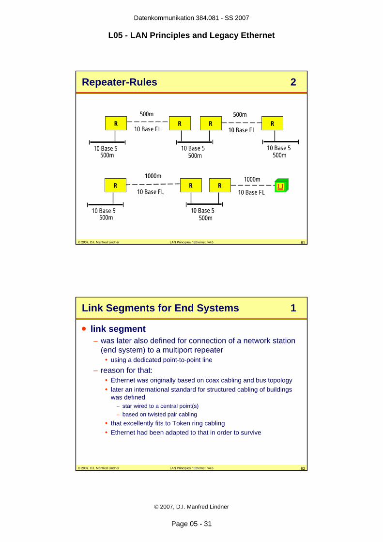
Link Segments for End Systems 1
• link segment – was later also defined for connection of a network station
(end system) to a multiport repeater • using a dedicated point-to-point line
– reason for that: • Ethernet was originally based on coax cabling and bus topology• later an international standard for structured cabling of buildings
was defined– star wired to a central point(s)– based on twisted pair cabling
• that excellently fits to Token ring cabling• Ethernet had been adapted to that in order to survive
Datenkommunikation 384.081 - SS 2007
L05 - LAN Principles and Legacy Ethernet
© 2007, D.I. Manfred Lindner
Page 05 - 32
© 2007, D.I. Manfred Lindner LAN Principles / Ethernet, v4.6 63
Structured Cabling (LAN)
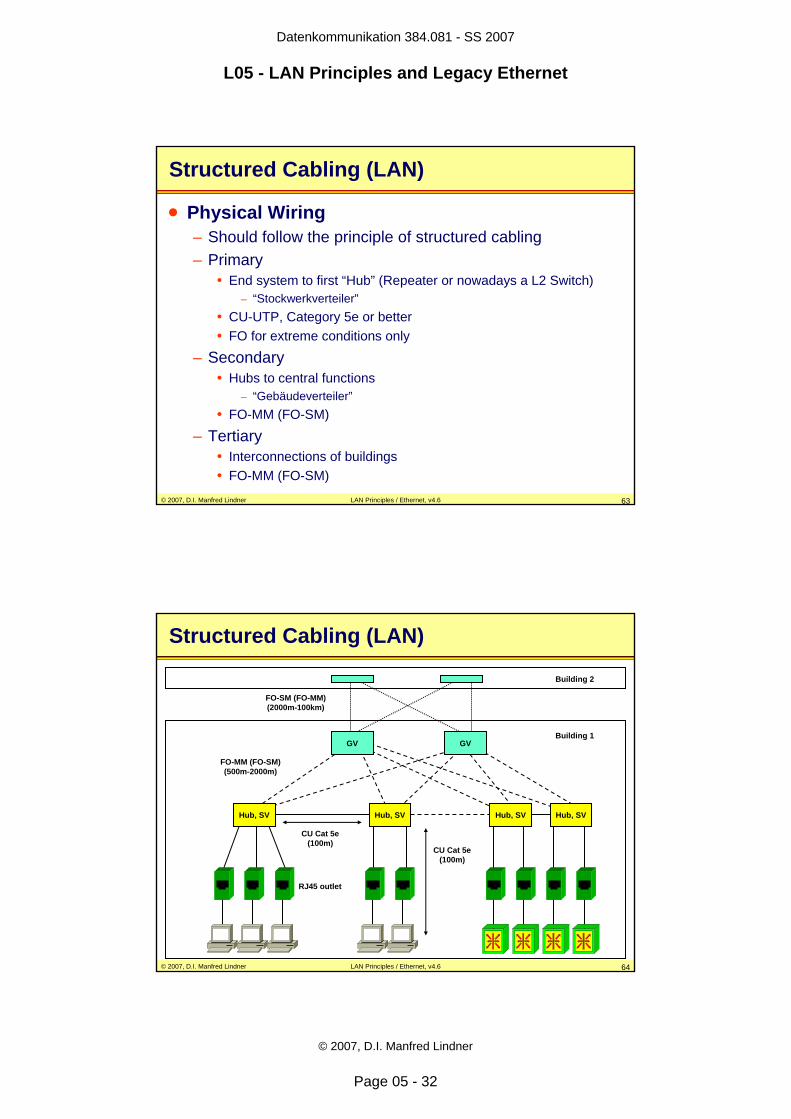
• Physical Wiring– Should follow the principle of structured cabling– Primary
• End system to first “Hub” (Repeater or nowadays a L2 Switch)– “Stockwerkverteiler”
• CU-UTP, Category 5e or better• FO for extreme conditions only
– Secondary• Hubs to central functions
– “Gebäudeverteiler”• FO-MM (FO-SM)
– Tertiary• Interconnections of buildings• FO-MM (FO-SM)
© 2007, D.I. Manfred Lindner LAN Principles / Ethernet, v4.6 64
Structured Cabling (LAN)
Hub, SV
GV
Hub, SV Hub, SVHub, SV
GV
CU Cat 5e (100m)
RJ45 outlet
CU Cat 5e (100m)
FO-MM (FO-SM) (500m-2000m)
FO-SM (FO-MM) (2000m-100km)
Building 1
Building 2
Datenkommunikation 384.081 - SS 2007
L05 - LAN Principles and Legacy Ethernet
© 2007, D.I. Manfred Lindner
Page 05 - 33
© 2007, D.I. Manfred Lindner LAN Principles / Ethernet, v4.6 65
Link Segments for End Systems 2
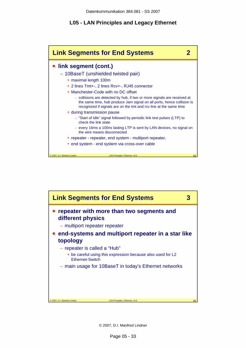
• link segment (cont.)– 10BaseT (unshielded twisted pair)
• maximal length 100m• 2 lines Tmt+-, 2 lines Rcv+-, RJ45 connector• Manchester-Code with no DC offset
– collisions are detected by hub, if two or more signals are received at the same time, hub produce Jam signal on all ports, hence collision is recognized if signals are on the tmt and rcv line at the same time
• during transmission pause– “Start of Idle” signal followed by periodic link test pulses (LTP) to
check the link state– every 16ms a 100ns lasting LTP is sent by LAN devices, no signal on
the wire means disconnected• repeater - repeater, end system - multiport repeater,• end system - end system via cross-over cable
© 2007, D.I. Manfred Lindner LAN Principles / Ethernet, v4.6 66
Link Segments for End Systems 3
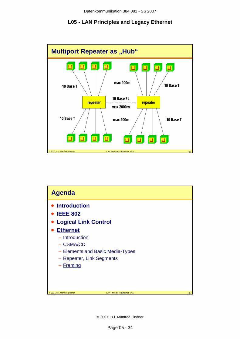
• repeater with more than two segments and different physics– multiport repeater repeater
• end-systems and multiport repeater in a star like topology– repeater is called a “Hub”
• be careful using this expression because also used for L2 Ethernet-Switch
– main usage for 10BaseT in today's Ethernet networks
Datenkommunikation 384.081 - SS 2007
L05 - LAN Principles and Legacy Ethernet
© 2007, D.I. Manfred Lindner
Page 05 - 34
© 2007, D.I. Manfred Lindner LAN Principles / Ethernet, v4.6 67
Multiport Repeater as „Hub“
10 Base FL
10 Base T 10 Base T
repeater repeater
max 100m
max 2000m
max 100m10 Base T 10 Base T
© 2007, D.I. Manfred Lindner LAN Principles / Ethernet, v4.6 68
Agenda
• Introduction• IEEE 802• Logical Link Control• Ethernet
– Introduction– CSMA/CD– Elements and Basic Media-Types– Repeater, Link Segments– Framing
Datenkommunikation 384.081 - SS 2007
L05 - LAN Principles and Legacy Ethernet
© 2007, D.I. Manfred Lindner
Page 05 - 35
© 2007, D.I. Manfred Lindner LAN Principles / Ethernet, v4.6 69
IEEE 802.3 Frame Format
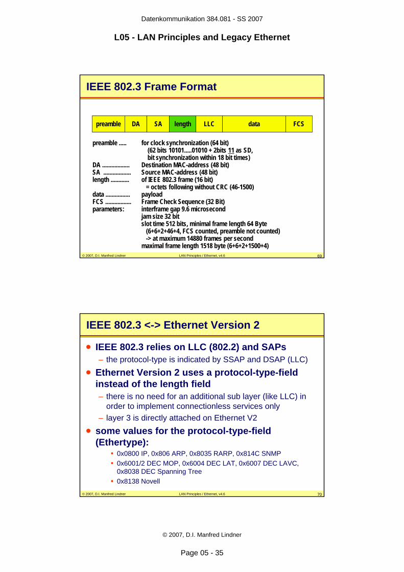
preamble DA SA length LLC data FCS
preamble ..... for clock synchronization (64 bit)(62 bits 10101.....01010 + 2bits 11 as SD,bit synchronization within 18 bit times)
DA .................. Destination MAC-address (48 bit) SA .................. Source MAC-address (48 bit)length ............ of IEEE 802.3 frame (16 bit)
= octets following without CRC (46-1500)data ................ payloadFCS ................. Frame Check Sequence (32 Bit)parameters: interframe gap 9.6 microsecond
jam size 32 bitslot time 512 bits, minimal frame length 64 Byte
(6+6+2+46+4, FCS counted, preamble not counted) -> at maximum 14880 frames per second
maximal frame length 1518 byte (6+6+2+1500+4)
© 2007, D.I. Manfred Lindner LAN Principles / Ethernet, v4.6 70
IEEE 802.3 <-> Ethernet Version 2
• IEEE 802.3 relies on LLC (802.2) and SAPs– the protocol-type is indicated by SSAP and DSAP (LLC)
• Ethernet Version 2 uses a protocol-type-field instead of the length field – there is no need for an additional sub layer (like LLC) in
order to implement connectionless services only– layer 3 is directly attached on Ethernet V2
• some values for the protocol-type-field (Ethertype):
• 0x0800 IP, 0x806 ARP, 0x8035 RARP, 0x814C SNMP• 0x6001/2 DEC MOP, 0x6004 DEC LAT, 0x6007 DEC LAVC,
0x8038 DEC Spanning Tree• 0x8138 Novell
Datenkommunikation 384.081 - SS 2007
L05 - LAN Principles and Legacy Ethernet
© 2007, D.I. Manfred Lindner
Page 05 - 36
© 2007, D.I. Manfred Lindner LAN Principles / Ethernet, v4.6 71
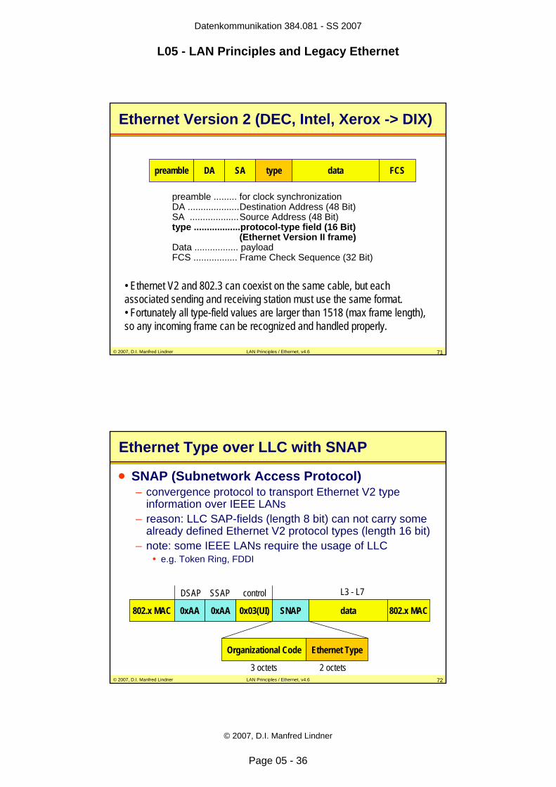
Ethernet Version 2 (DEC, Intel, Xerox -> DIX)
preamble DA SA type data FCS
preamble ......... for clock synchronizationDA ....................Destination Address (48 Bit)SA ...................Source Address (48 Bit)type ..................protocol-type field (16 Bit)
(Ethernet Version II frame)Data ................. payloadFCS ................. Frame Check Sequence (32 Bit)
• Ethernet V2 and 802.3 can coexist on the same cable, but each associated sending and receiving station must use the same format.• Fortunately all type-field values are larger than 1518 (max frame length), so any incoming frame can be recognized and handled properly.
© 2007, D.I. Manfred Lindner LAN Principles / Ethernet, v4.6 72
Ethernet Type over LLC with SNAP
• SNAP (Subnetwork Access Protocol)– convergence protocol to transport Ethernet V2 type
information over IEEE LANs– reason: LLC SAP-fields (length 8 bit) can not carry some
already defined Ethernet V2 protocol types (length 16 bit)– note: some IEEE LANs require the usage of LLC
• e.g. Token Ring, FDDI
802.x MAC 0xAA 0xAA 0x03(UI) SNAP data 802.x MAC
Organizational Code Ethernet Type
3 octets 2 octets
DSAP SSAP control L3 - L7
Datenkommunikation 384.081 - SS 2007
L05 - LAN Principles and Legacy Ethernet
© 2007, D.I. Manfred Lindner
Page 05 - 37
© 2007, D.I. Manfred Lindner LAN Principles / Ethernet, v4.6 73
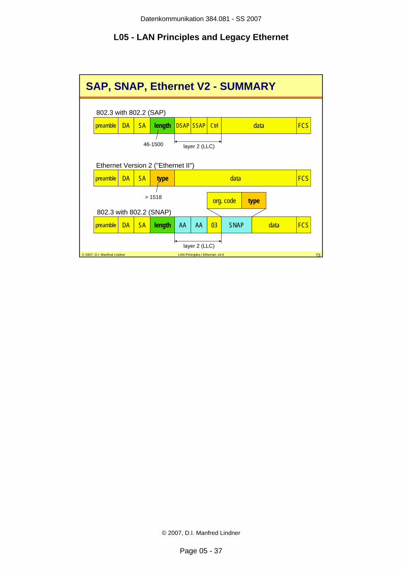
SAP, SNAP, Ethernet V2 - SUMMARY
preamble DA SA length data FCSDSAP SSAP Ctrl
802.3 with 802.2 (SAP)
layer 2 (LLC)
preamble DA SA type data FCS
preamble DA SA length data FCSAA AA 03
layer 2 (LLC)
Ethernet Version 2 ("Ethernet II")
802.3 with 802.2 (SNAP)
46-1500
> 1518
SNAP
typeorg. code