Embed Size (px)
Citation preview
Load Testing After Strengthening Of A Pre-
stressed Double Tee Beam That Had Failed In
Shear
Nestore Galati, PhD, PE(1) and Tarek Alkhrdaji, PhD, PE(1)
STRUCTURAL TECHNOLOGIES, 10150 Old Columbia Road,
Columbia, MD 21046
Introduction
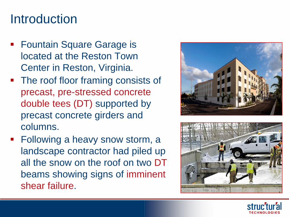
▪ Fountain Square Garage is
located at the Reston Town
Center in Reston, Virginia.
▪ The roof floor framing consists of
precast, pre-stressed concrete
double tees (DT) supported by
precast concrete girders and
columns.
▪ Following a heavy snow storm, a
landscape contractor had piled up
all the snow on the roof on two DT
beams showing signs of imminent
shear failure.
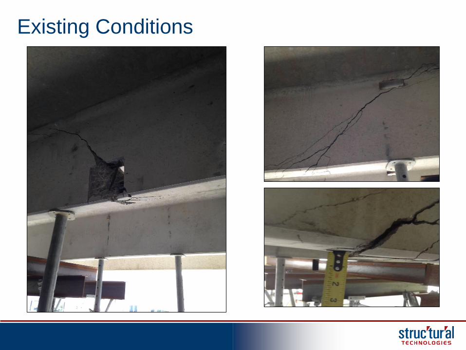
Existing Conditions
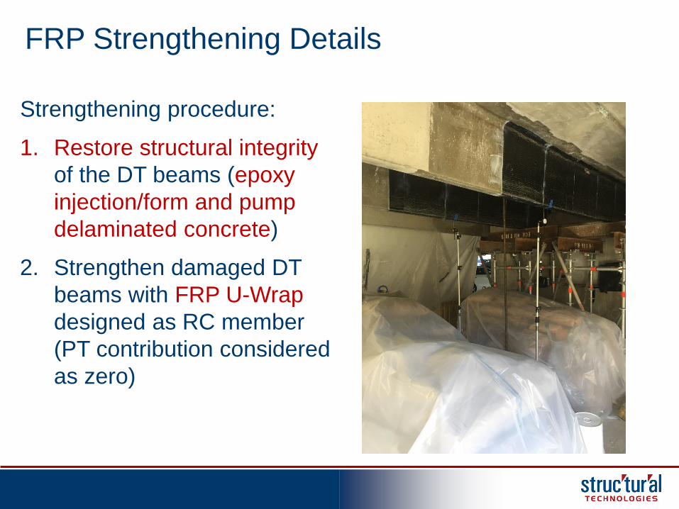
FRP Strengthening Details
Strengthening procedure:
1. Restore structural integrity
of the DT beams (epoxy
injection/form and pump
delaminated concrete)
2. Strengthen damaged DT
beams with FRP U-Wrap
designed as RC member
(PT contribution considered
as zero)
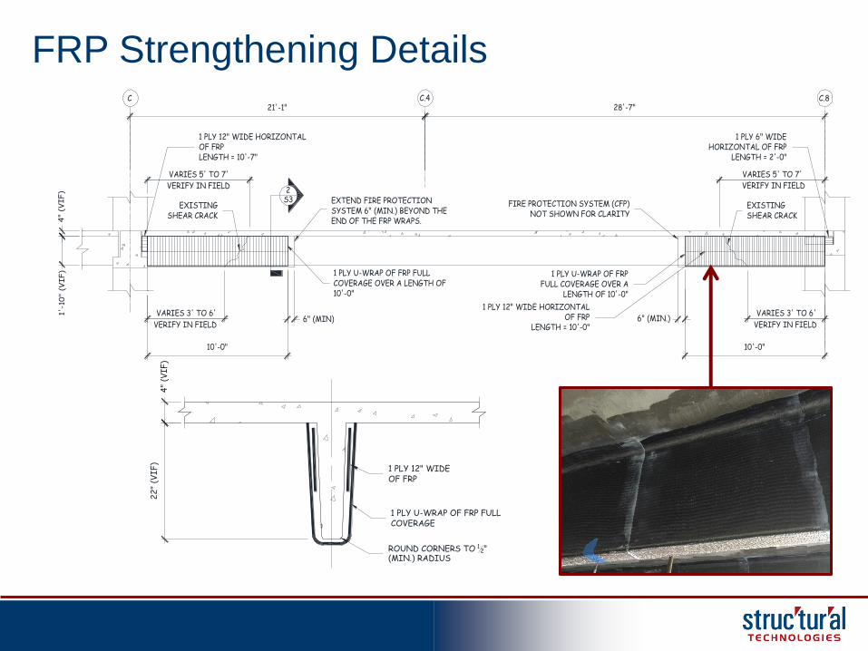
FRP Strengthening Details
1 PLY U-WRAP OF FRP FULLCOVERAGE
1 PLY 12" WIDEOF FRP
ROUND CORNERS TO 12"(MIN.) RADIUS
S32 SECTION - TEE STEM FRP DETAIL
4"
(VIF
)2
2"
(VIF
)
EXISTINGSHEAR CRACK
21'-1" 28'-7"
1 PLY 12" WIDE HORIZONTALOF FRPLENGTH = 10'-7"
1 PLY U-WRAP OF FRPFULL COVERAGE OVER A
LENGTH OF 10'-0"
1 PLY 6" WIDEHORIZONTAL OF FRP
LENGTH = 2'-0"
10'-0"
1 PLY 12" WIDE HORIZONTALOF FRP
LENGTH = 10'-0"
1 PLY U-WRAP OF FRP FULLCOVERAGE OVER A LENGTH OF10'-0"
10'-0"
S32
4"
(VIF
)1'
-10
" (V
IF
)
C.4 C.8C
S31 ELEVATION - TYPICAL PRECAST DOUBLE TEE STEM FRP DETAIL
EXTEND FIRE PROTECTIONSYSTEM 6" (MIN.) BEYOND THEEND OF THE FRP WRAPS.
FIRE PROTECTION SYSTEM (CFP)NOT SHOWN FOR CLARITY
6" (MIN)VARIES 3' TO 6'
VERIFY IN FIELD
VARIES 5' TO 7'
VERIFY IN FIELD
6" (MIN.)VARIES 3' TO 6'
VERIFY IN FIELD
VARIES 5' TO 7'
VERIFY IN FIELD
EXISTINGSHEAR CRACK
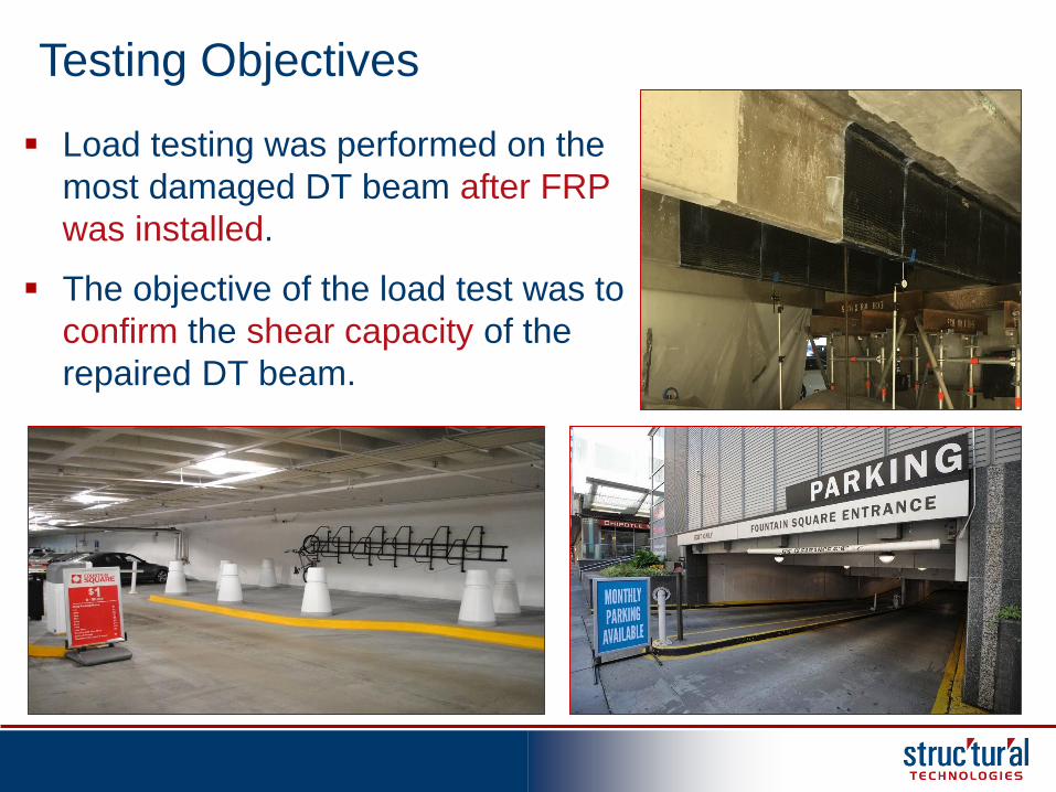
▪ Load testing was performed on the
most damaged DT beam after FRP
was installed.
▪ The objective of the load test was to
confirm the shear capacity of the
repaired DT beam.
Testing Objectives
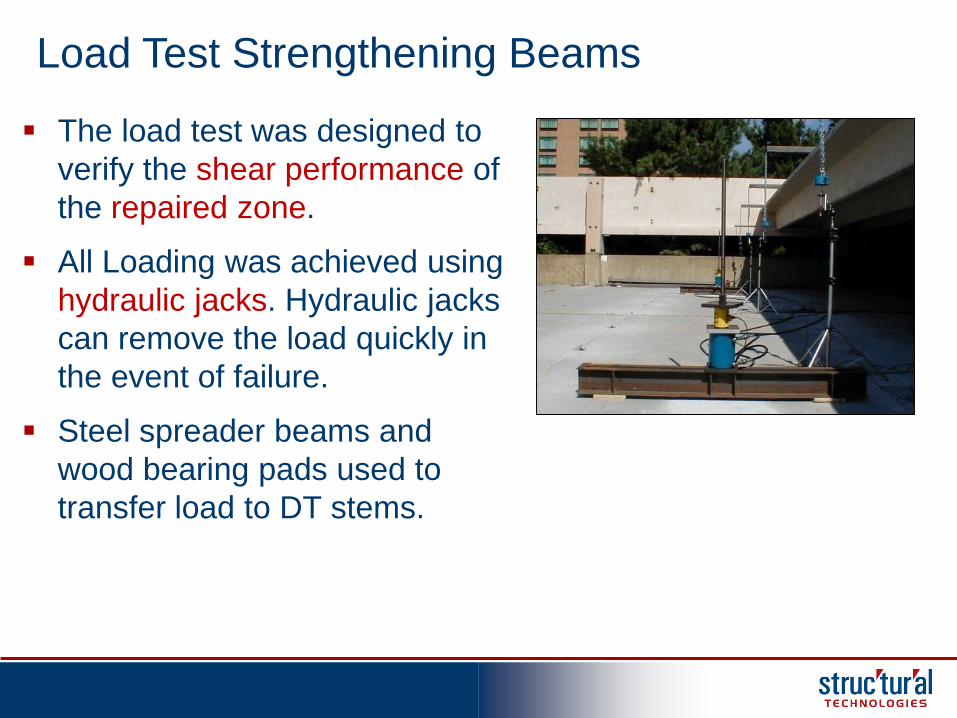
▪ The load test was designed to
verify the shear performance of
the repaired zone.
▪ All Loading was achieved using
hydraulic jacks. Hydraulic jacks
can remove the load quickly in
the event of failure.
▪ Steel spreader beams and
wood bearing pads used to
transfer load to DT stems.
Load Test Strengthening Beams
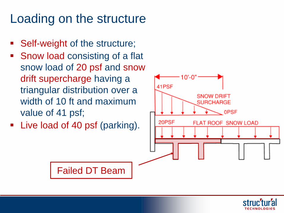
Loading on the structure
▪ Self-weight of the structure;
▪ Snow load consisting of a flat
snow load of 20 psf and snow
drift supercharge having a
triangular distribution over a
width of 10 ft and maximum
value of 41 psf;
▪ Live load of 40 psf (parking).
Failed DT Beam
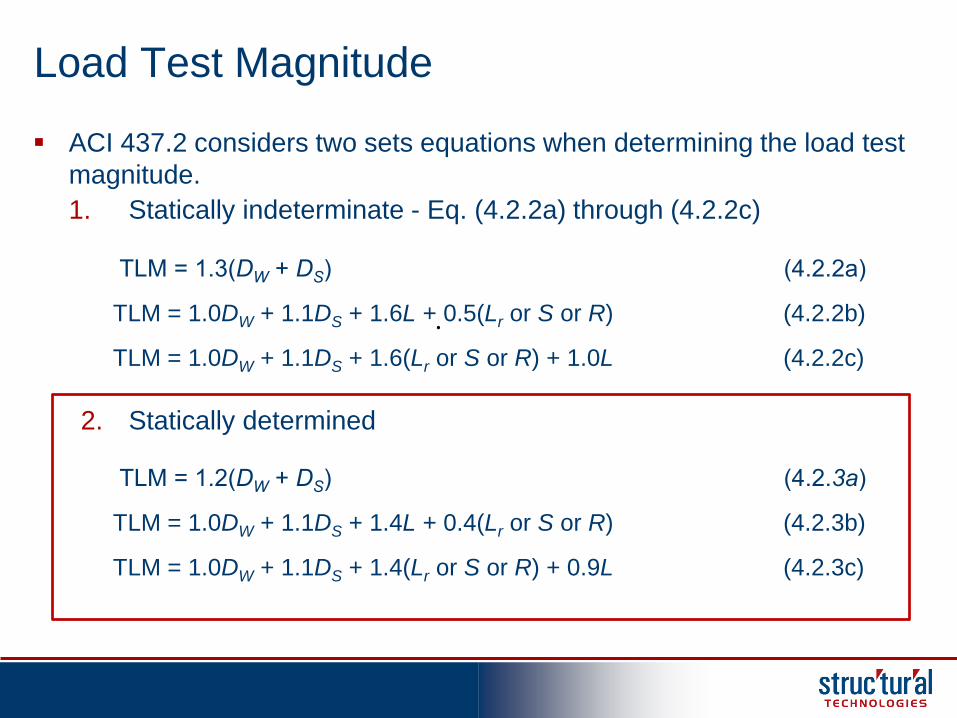
Load Test Magnitude
▪ ACI 437.2 considers two sets equations when determining the load test
magnitude.
1. Statically indeterminate - Eq. (4.2.2a) through (4.2.2c)
2. Statically determined
TLM = 1.3(DW + DS) (4.2.2a)
TLM = 1.0DW + 1.1DS + 1.6L + 0.5(Lr or S or R) (4.2.2b)
TLM = 1.0DW + 1.1DS + 1.6(Lr or S or R) + 1.0L (4.2.2c)
∙
TLM = 1.2(DW + DS) (4.2.3a)
TLM = 1.0DW + 1.1DS + 1.4L + 0.4(Lr or S or R) (4.2.3b)
TLM = 1.0DW + 1.1DS + 1.4(Lr or S or R) + 0.9L (4.2.3c)
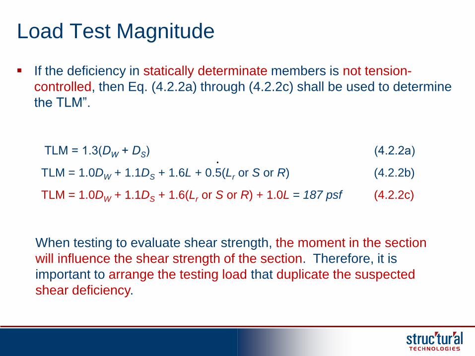
Load Test Magnitude
▪ If the deficiency in statically determinate members is not tension-
controlled, then Eq. (4.2.2a) through (4.2.2c) shall be used to determine
the TLM”.
TLM = 1.3(DW + DS) (4.2.2a)
TLM = 1.0DW + 1.1DS + 1.6L + 0.5(Lr or S or R) (4.2.2b)
TLM = 1.0DW + 1.1DS + 1.6(Lr or S or R) + 1.0L = 187 psf (4.2.2c)
∙
When testing to evaluate shear strength, the moment in the section
will influence the shear strength of the section. Therefore, it is
important to arrange the testing load that duplicate the suspected
shear deficiency.
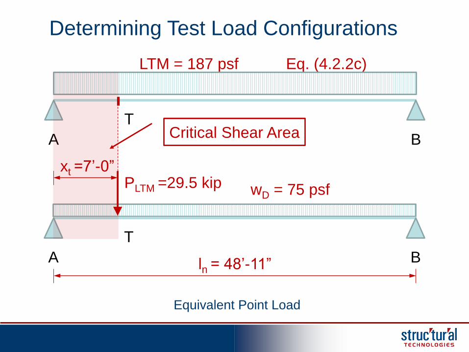
Determining Test Load Configurations
LTM = 187 psf Eq. (4.2.2c)
PLTM =29.5 kip
A Bln = 48’-11”
T
A B
T
xt =7’-0”
wD = 75 psf
Equivalent Point Load
Critical Shear Area
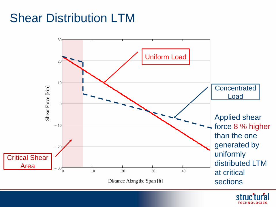
Shear Distribution LTM
Concentrated
Load
Applied shear
force 8 % higher
than the one
generated by
uniformly
distributed LTM
at critical
sections
0 10 20 30 4030−
20−
10−
0
10
20
30
Distance Along the Span [ft]
Sh
ear
Fo
rce
[kip
]
Critical Shear
Area
Uniform Load
0 10 20 30 400
100
200
300
Distance Along the Span [ft]
Ben
din
g M
om
ent
[kip
-ft]
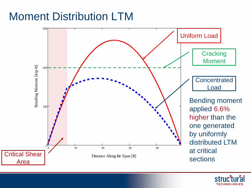
Moment Distribution LTM
Critical Shear
Area
Uniform Load
Concentrated
Load
Bending moment
applied 6.6%
higher than the
one generated
by uniformly
distributed LTM
at critical
sections
Cracking
Moment
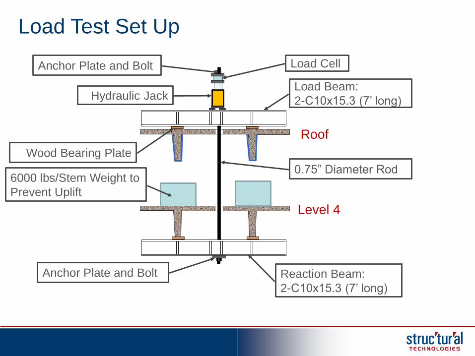
Load Test Set Up
Reaction Beam:
2-C10x15.3 (7’ long)
Load Beam:
2-C10x15.3 (7’ long)
0.75” Diameter Rod
Anchor Plate and Bolt
Anchor Plate and Bolt
Wood Bearing Plate
Hydraulic Jack
Load Cell
6000 lbs/Stem Weight to
Prevent Uplift
Roof
Level 4
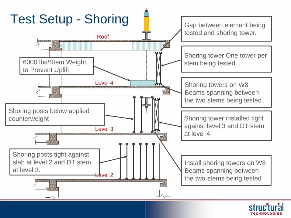
Test Setup - Shoring
Shoring tower One tower per
stem being tested.
Gap between element being
tested and shoring tower.
Shoring posts tight against
slab at level 2 and DT stem
at level 3.
Roof
Level 4
Level 3
Level 2
Shoring tower installed tight
against level 3 and DT stem
at level 4.
Shoring towers on W8
Beams spanning between
the two stems being tested.
Shoring posts below applied
counterweight
Install shoring towers on W8
Beams spanning between
the two stems being tested
6000 lbs/Stem Weight
to Prevent Uplift
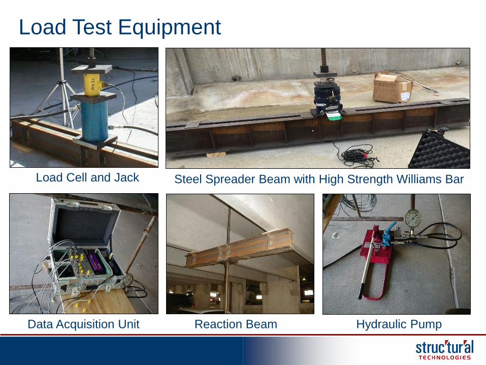
Load Test Equipment
Load Cell and Jack
Data Acquisition Unit
Steel Spreader Beam with High Strength Williams Bar
Reaction Beam Hydraulic Pump
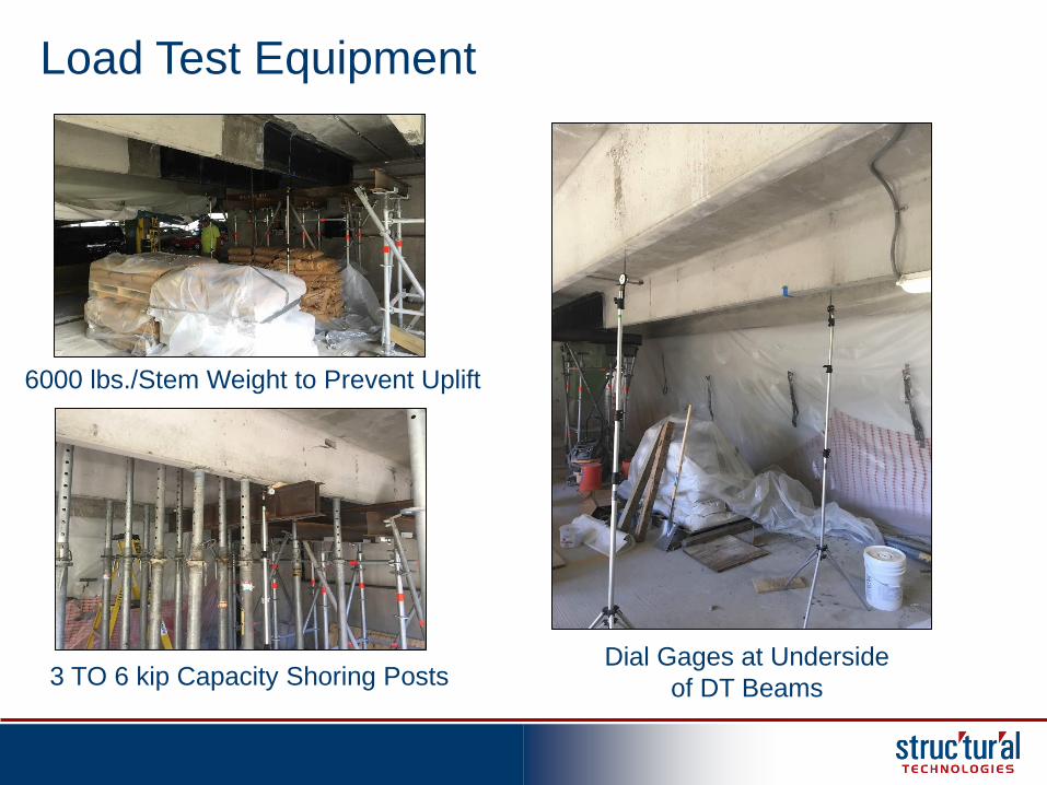
Load Test Equipment
6000 lbs./Stem Weight to Prevent Uplift
3 TO 6 kip Capacity Shoring PostsDial Gages at Underside
of DT Beams
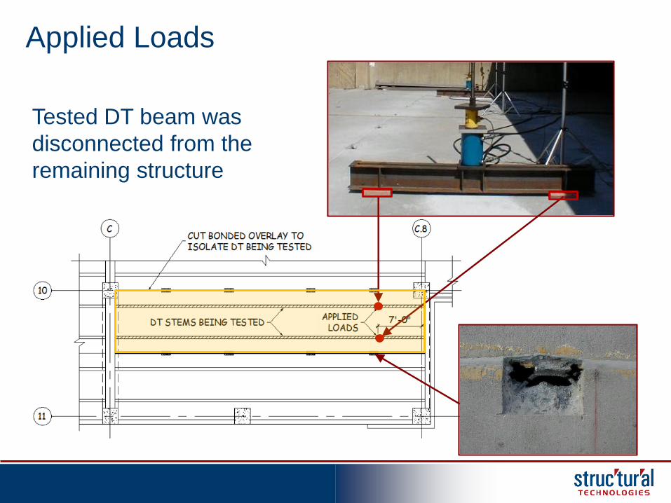
Applied Loads
Tested DT beam was
disconnected from the
remaining structure
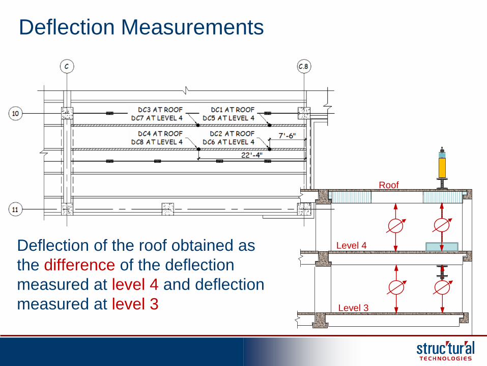
Deflection of the roof obtained as
the difference of the deflection
measured at level 4 and deflection
measured at level 3
Deflection Measurements
Roof
Level 4
Level 3
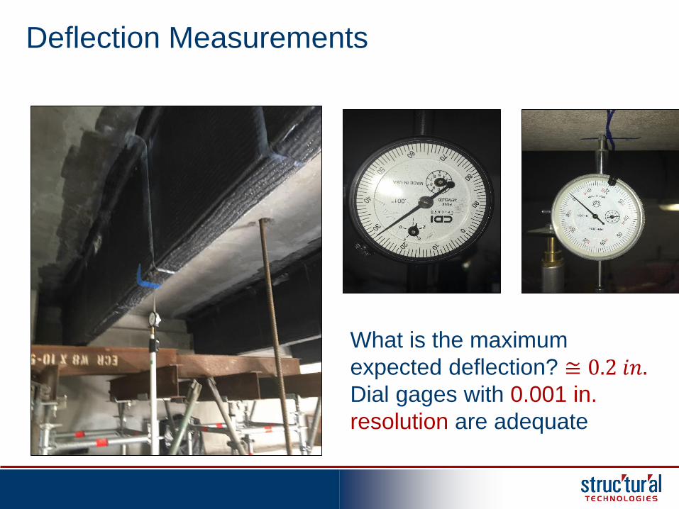
Deflection Measurements
What is the maximum
expected deflection? ≅ 0.2 𝑖𝑛.Dial gages with 0.001 in.
resolution are adequate
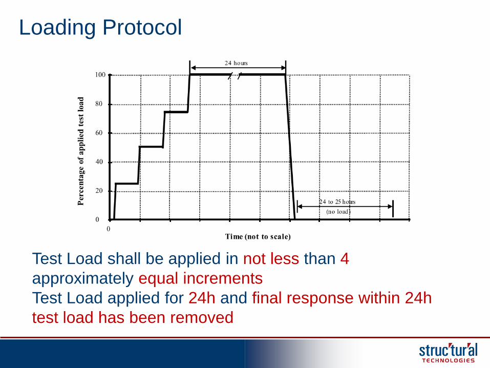
Loading Protocol
Test Load shall be applied in not less than 4
approximately equal increments
Test Load applied for 24h and final response within 24h
test load has been removed
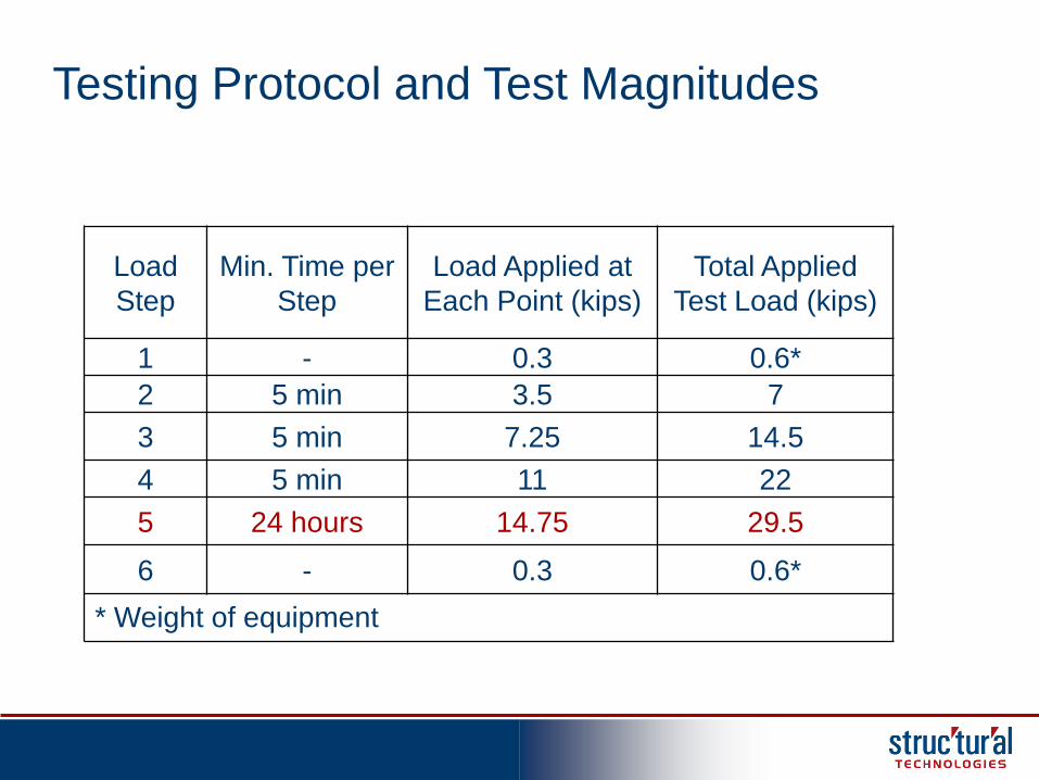
Testing Protocol and Test Magnitudes
Load
Step
Min. Time per
Step
Load Applied at
Each Point (kips)
Total Applied
Test Load (kips)
1 - 0.3 0.6*
2 5 min 3.5 7
3 5 min 7.25 14.5
4 5 min 11 22
5 24 hours 14.75 29.5
6 - 0.3 0.6*
* Weight of equipment
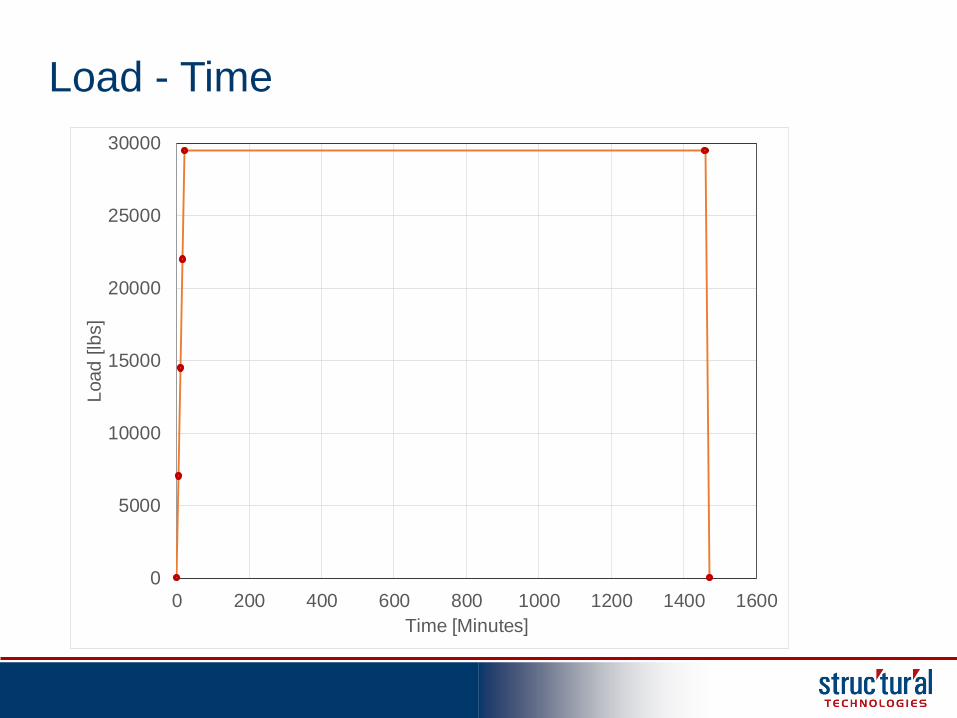
Load - Time
0
5000
10000
15000
20000
25000
30000
0 200 400 600 800 1000 1200 1400 1600
Load
[lb
s]
Time [Minutes]
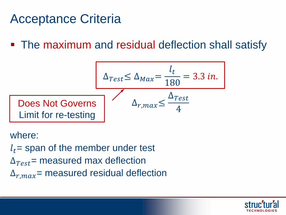
Acceptance Criteria
▪ The maximum and residual deflection shall satisfy
∆𝑇𝑒𝑠𝑡≤ ∆𝑀𝑎𝑥=𝑙𝑡180
= 3.3 𝑖𝑛.
∆𝑟,𝑚𝑎𝑥≤∆𝑇𝑒𝑠𝑡4
where:
𝑙𝑡= span of the member under test
∆𝑇𝑒𝑠𝑡= measured max deflection
∆𝑟,𝑚𝑎𝑥= measured residual deflection
Does Not Governs
Limit for re-testing
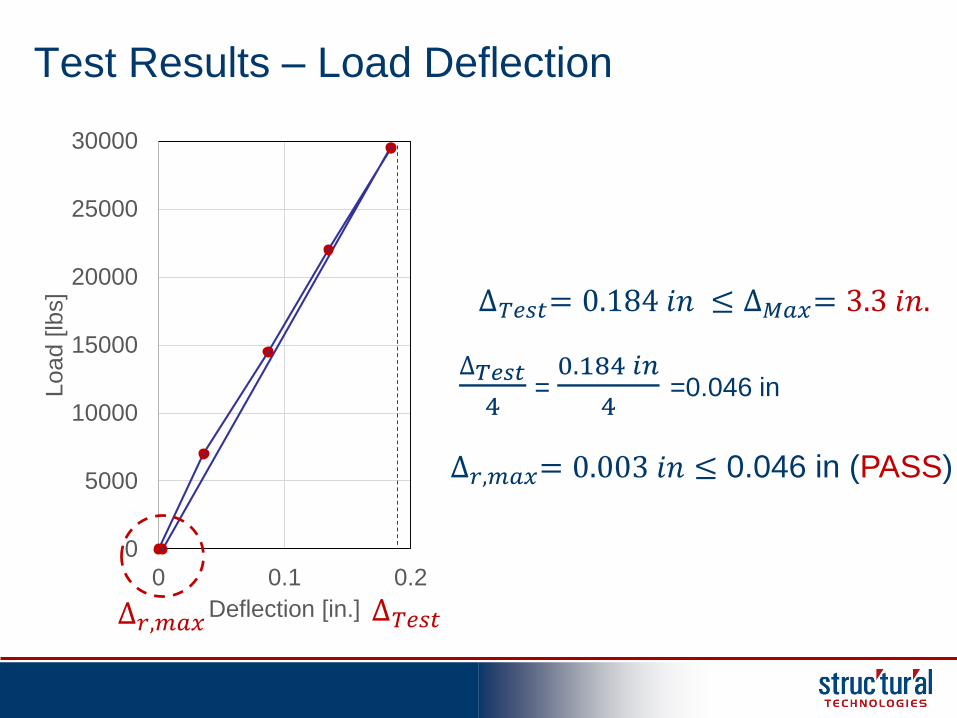
Test Results – Load Deflection
0
5000
10000
15000
20000
25000
30000
0 0.1 0.2
Load [
lbs]
Deflection [in.]
∆𝑇𝑒𝑠𝑡= 0.184 𝑖𝑛 ≤ ∆𝑀𝑎𝑥= 3.3 𝑖𝑛.
∆𝑇𝑒𝑠𝑡
4= 0.184 𝑖𝑛
4=0.046 in
∆𝑟,𝑚𝑎𝑥= 0.003 𝑖𝑛 ≤ 0.046 in (PASS)
∆𝑟,𝑚𝑎𝑥 ∆𝑇𝑒𝑠𝑡
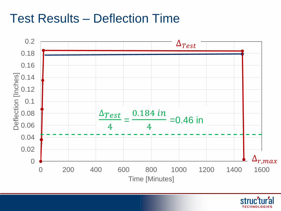
Test Results – Deflection Time
0
0.02
0.04
0.06
0.08
0.1
0.12
0.14
0.16
0.18
0.2
0 200 400 600 800 1000 1200 1400 1600
Deflection [
Inches]
Time [Minutes]
∆𝑇𝑒𝑠𝑡
∆𝑇𝑒𝑠𝑡
4= 0.184 𝑖𝑛
4=0.46 in
∆𝑟,𝑚𝑎𝑥
Conclusions
▪ The monotonic load testing was used to verify the shear
capacity of a double tee beam failed in shear.
▪ The load test was designed to verify the shear performance
of only the repaired zone. The remaining portion of the
beams was below cracking.
▪ The structure met the acceptance criteria of ACI 437.2 and
stayed elastic during the load test.
▪ Is a deflection criteria meaningful when testing for shear or
would a pass/fail criteria be more feasible?

Thank You
Any Questions?